EP2548379B1 - Automatic audio source switching - Google Patents
Automatic audio source switching Download PDFInfo
- Publication number
- EP2548379B1 EP2548379B1 EP11709556.2A EP11709556A EP2548379B1 EP 2548379 B1 EP2548379 B1 EP 2548379B1 EP 11709556 A EP11709556 A EP 11709556A EP 2548379 B1 EP2548379 B1 EP 2548379B1
- Authority
- EP
- European Patent Office
- Prior art keywords
- audio signal
- audio
- display device
- signal
- video display
- Prior art date
- Legal status (The legal status is an assumption and is not a legal conclusion. Google has not performed a legal analysis and makes no representation as to the accuracy of the status listed.)
- Active
Links
Images



Classifications
-
- H—ELECTRICITY
- H04—ELECTRIC COMMUNICATION TECHNIQUE
- H04R—LOUDSPEAKERS, MICROPHONES, GRAMOPHONE PICK-UPS OR LIKE ACOUSTIC ELECTROMECHANICAL TRANSDUCERS; ELECTRIC HEARING AIDS; PUBLIC ADDRESS SYSTEMS
- H04R5/00—Stereophonic arrangements
- H04R5/04—Circuit arrangements, e.g. for selective connection of amplifier inputs/outputs to loudspeakers, for loudspeaker detection, or for adaptation of settings to personal preferences or hearing impairments
-
- H—ELECTRICITY
- H04—ELECTRIC COMMUNICATION TECHNIQUE
- H04N—PICTORIAL COMMUNICATION, e.g. TELEVISION
- H04N21/00—Selective content distribution, e.g. interactive television or video on demand [VOD]
- H04N21/40—Client devices specifically adapted for the reception of or interaction with content, e.g. set-top-box [STB]; Operations thereof
- H04N21/43—Processing of content or additional data, e.g. demultiplexing additional data from a digital video stream; Elementary client operations, e.g. monitoring of home network or synchronising decoder's clock; Client middleware
- H04N21/436—Interfacing a local distribution network, e.g. communicating with another STB or one or more peripheral devices inside the home
- H04N21/4363—Adapting the video stream to a specific local network, e.g. a Bluetooth® network
- H04N21/43632—Adapting the video stream to a specific local network, e.g. a Bluetooth® network involving a wired protocol, e.g. IEEE 1394
- H04N21/43635—HDMI
-
- H—ELECTRICITY
- H04—ELECTRIC COMMUNICATION TECHNIQUE
- H04N—PICTORIAL COMMUNICATION, e.g. TELEVISION
- H04N5/00—Details of television systems
- H04N5/44—Receiver circuitry for the reception of television signals according to analogue transmission standards
- H04N5/60—Receiver circuitry for the reception of television signals according to analogue transmission standards for the sound signals
-
- G—PHYSICS
- G06—COMPUTING OR CALCULATING; COUNTING
- G06F—ELECTRIC DIGITAL DATA PROCESSING
- G06F3/00—Input arrangements for transferring data to be processed into a form capable of being handled by the computer; Output arrangements for transferring data from processing unit to output unit, e.g. interface arrangements
- G06F3/16—Sound input; Sound output
- G06F3/162—Interface to dedicated audio devices, e.g. audio drivers, interface to CODECs
-
- G—PHYSICS
- G08—SIGNALLING
- G08C—TRANSMISSION SYSTEMS FOR MEASURED VALUES, CONTROL OR SIMILAR SIGNALS
- G08C23/00—Non-electrical signal transmission systems, e.g. optical systems
- G08C23/04—Non-electrical signal transmission systems, e.g. optical systems using light waves, e.g. infrared
-
- H—ELECTRICITY
- H04—ELECTRIC COMMUNICATION TECHNIQUE
- H04N—PICTORIAL COMMUNICATION, e.g. TELEVISION
- H04N21/00—Selective content distribution, e.g. interactive television or video on demand [VOD]
- H04N21/40—Client devices specifically adapted for the reception of or interaction with content, e.g. set-top-box [STB]; Operations thereof
- H04N21/47—End-user applications
-
- H—ELECTRICITY
- H04—ELECTRIC COMMUNICATION TECHNIQUE
- H04N—PICTORIAL COMMUNICATION, e.g. TELEVISION
- H04N7/00—Television systems
- H04N7/08—Systems for the simultaneous or sequential transmission of more than one television signal, e.g. additional information signals, the signals occupying wholly or partially the same frequency band, e.g. by time division
- H04N7/087—Systems for the simultaneous or sequential transmission of more than one television signal, e.g. additional information signals, the signals occupying wholly or partially the same frequency band, e.g. by time division with signal insertion during the vertical blanking interval only
- H04N7/088—Systems for the simultaneous or sequential transmission of more than one television signal, e.g. additional information signals, the signals occupying wholly or partially the same frequency band, e.g. by time division with signal insertion during the vertical blanking interval only the inserted signal being digital
-
- H—ELECTRICITY
- H04—ELECTRIC COMMUNICATION TECHNIQUE
- H04R—LOUDSPEAKERS, MICROPHONES, GRAMOPHONE PICK-UPS OR LIKE ACOUSTIC ELECTROMECHANICAL TRANSDUCERS; ELECTRIC HEARING AIDS; PUBLIC ADDRESS SYSTEMS
- H04R2420/00—Details of connection covered by H04R, not provided for in its groups
- H04R2420/01—Input selection or mixing for amplifiers or loudspeakers
-
- H—ELECTRICITY
- H04—ELECTRIC COMMUNICATION TECHNIQUE
- H04R—LOUDSPEAKERS, MICROPHONES, GRAMOPHONE PICK-UPS OR LIKE ACOUSTIC ELECTROMECHANICAL TRANSDUCERS; ELECTRIC HEARING AIDS; PUBLIC ADDRESS SYSTEMS
- H04R2420/00—Details of connection covered by H04R, not provided for in its groups
- H04R2420/03—Connection circuits to selectively connect loudspeakers or headphones to amplifiers
Definitions
- This disclosure relates to an audio/video system and, more specifically to a video display with a supplemental audio system.
- TVs Many modern televisions (“TVs”) have significant audio/video (“A/V”) source switching capabilities.
- A/V audio/video
- customers often choose to connect their A/V sources (e.g. cable box, DVD player) directly to the TV using, for example, HDMI cables.
- A/V sources e.g. cable box, DVD player
- HDMI cables This eliminates the need for an external home theater A/V receiver to switch audio/video signals.
- the HDMI inputs and audio outputs of TVs are technically capable of supplying a multichannel audio output (e.g. Dolby Digital 5.1) from the TV to a supplemental audio system being used with the TV.
- the audio signal available at a TV's audio output is often not multichannel. Instead, the audio output from the TV is typically a down-mixed 2 channel signal (e.g. PCM 2.0). This down-mixing (e.g. via summation) results in lost audio information (e.g. bass and dynamic range) that can limit the sound quality of a supplemental sound system that
- EP1853086 and EP0866638 disclose an audiovisual amplifier capable of selectively switching between a multichannel reproducing mode and a two-channel stereo reproducing mode.
- the present invention proposes a method and an apparatus as recited in the appended set of claims.
- a method for automatically switching an audio source includes the steps of receiving an audio signal from a video display device, and receiving a digital audio signal from one of a plurality of audio/video source devices which each can supply audio and video information to the video display device.
- the digital audio signal is compared with the audio signal from the video display device.
- the digital audio signal is output to a supplemental audio system of the video display device when the comparing step indicates that the digital audio signal and the audio signal from the video display device contain substantially similar audio programs.
- Embodiments may include one or more of the following features.
- the audio signal received from the video display device is an analog signal.
- the audio signal received from the video display device is a digital signal.
- the video display device is a television.
- the audio signal received from the video display device is supplied to the video device from one of the audio/video source devices.
- the digital audio signal received from the source device has 6 or more channels.
- the digital audio signal received from the source device has more channels than the audio signal received from the video display device.
- the receiving step includes receiving a digital audio signal from each of the plurality of audio/video source devices.
- the comparing step utilizes information beyond what is included in the audio signal and digital audio signal.
- the information that is beyond what is included in the audio signal and digital audio signal includes the presence or absence of a wireless signal from a remote control.
- an apparatus for automatically switching an audio source includes an audio receiver that can receive (a) an audio signal from a video display device, and (b) a digital audio signal from one of a plurality of audio/video source devices which each can supply audio and video information to the video display device.
- the audio receiver compares the digital audio signal with the audio signal from the video display device and outputs the digital audio signal to a supplemental audio system of the video display device when the digital audio signal and the audio signal from the video display device contain substantially similar audio programs.
- Embodiments may include one or more of the following features.
- the audio signal received from the video display device is an analog signal.
- the audio signal received from the video display device is a digital signal.
- the video display device is a television.
- the audio signal received from the video display device is supplied to the video device from one of the audio/video source devices.
- the digital audio signal received from the source device has 5 or more channels.
- the digital audio signal received from the source device has more channels than the audio signal received from the video display device.
- a method for automatically switching an audio source includes the steps of receiving a digital audio signal from one of a plurality of audio/video source devices which each can supply video information to a video display device, and receiving an indication from the video display device that the digital audio signal should be transmitted to a supplemental audio system.
- the digital audio signal is output to the supplemental audio system.
- An embodiment may include the following feature.
- the indication is an audio signal that substantially matches the digital audio signal.
- a supplemental audio system for use with their video display (e.g. a TV) to provide enhanced audio reproduction while watching a video program on their video display.
- the disclosure below discusses how to automatically switch the highest quality audio signal to the supplemental speaker system when AN sources (e.g. DVD player, cable box) are directly connected to the TV.
- Fig. 1 discloses an audio/video system 60 which includes a video display device 62 such as a liquid crystal or plasma display.
- the display 62 includes integrated speakers (acoustic drivers) 63 and an infra-red (IR) receiver 67.
- a pair of audio/video source devices such as a cable box 68 and a digital video disc (DVD) player 70, are attached to the display 62 by, for example, respective HDMI cables 72 and 74.
- Additional A/V source devices can be connected to the display 62. Any of the AN source devices can be connected to the display 62 by an analog connection (e.g. component video with a separate audio connection) instead of a digital connection (e.g. HDMI).
- the A/V source devices can each supply audio (e.g.
- Dolby Digital 5.1 with six channels Dolby Digital 5.1 with six channels
- Another example of an A/V device that can be connected to the display 62 is a computer (not shown).
- the display 62 can also be connected directly to the internet which can supply AN information to the display for presentation.
- Use is made of a source switching capability included in the display 62 to select AV information from AN device 68 or 70 to present to the user.
- the user operates a wireless remote control 88 (e.g. IR or RF) to transmit a signal to the IR receiver 67 to select the desired AN information from device 68 or 70 for presentation by the display 62.
- the user can operate buttons on the display 62 to select the desired AN device 68 or 70.
- the display outputs an audio signal over a cable 66 to an audio receiver 64.
- the information in the output audio signal was supplied to the display 62 by the selected A/V device 68 or 70. If cable 66 is a digital audio cable (such as optical or coaxial digital audio), then the output audio signal is in digital form (likely a PCM 2.0 signal). If cable 66 is a traditional stereo audio cable pair, then the audio signal output by display 62 is in analog form.
- the output audio signal is transmitted over cable 66 and received by a controller 61 in an audio receiver 64.
- the controller 61 is also connected to and can receive respective digital audio signals from the cable box 68 and DVD player 70 over respective digital audio cables 80 and 82.
- the audio signal output to the controller 61 by each of the cable box 68 and the DVD player 70 would typically be a high quality, multichannel digital audio signal (e.g. a Dolby Digital 5.1 audio signal).
- These high quality digital audio signals can provide a higher quality acoustic performance than the audio signal output by the display 62 over cable 66 because the latter is usually down-mixed.
- the reason the display 62 down-mixes the received audio signals is to optimize the audio output from the integrated speakers 63.
- Speakers 63 typically have significantly reduced performance as compared to an external audio system, and therefore the downmixed signals are sometimes greatly reduced in dynamic range and spectral extension. This downmixed signal cannot provide the dynamic range and bass performance that can be provided by the high quality digital audio signals provided directly from the AV sources 68 and 70.
- a supplemental speaker system 76 is connected to the controller 61 of the audio receiver 64 by a cable 78.
- the speaker system 76 may have only a single acoustic driver (mono audio), or it may have multiple acoustic drivers arranged in, for example, a stereo, 5.1 or 7.2 audio system.
- a 5.1 system has the following speakers: left front, center, right front, left surround, right surround and bass (low frequency effects).
- the speaker system could also be a 1.0 or 1.1 type of system which is sometimes referred to as a "soundbar" (with or without a separate bass speaker).
- the speaker system preferably includes audio processing (such as a digital signal processor) and one or more power amplifiers
- audio processing such as a digital signal processor
- the audio receiver 64 and the supplemental speaker system 76 can be combined into a single unit in which the functions of the controller 61 are performed by the audio processor of the speaker system 76. This type of arrangement can result in reduced costs for the entire system.
- the controller 61 checks to see if it is receiving an audio signal from the display 62 over the cable 66. When a signal is being received, the controller 61 decodes and processes this signal as required and passes it to the speaker system 76 over cable 78 at a step 94. This step provides audio output while the controller 61 is checking to see if there is a higher quality (multi-channel) audio signal available directly from the AN sources 68 and 70.
- the controller 61 checks to see if the received audio signal on cable 66 contains greater than two channels. When the signal on cable 66 is greater than two channels, this signal is continued to be processed and sent to the speaker system 76 as it is a multi-channel signal. If the received audio signal from cable 66 is a mono or two channel signal, then controller 61 compares this signal with the respective digital audio signals, if any, being received from cables 80 and 82 (and decoded) to look for a match between the signal on cable 66 and one of the signals on cables 80 and 82 (step 98). In other words, the controller 61 determines if the audio program on cable 66 is substantially similar to any of the audio programs on cables 80 and 82. When the signal on cable 66 does not match any of the signals on cables 80 or 82, the signal on cable 66 is continued to be processed and sent to the speaker system 76.
- the matching of signals described at the end of the previous paragraph can be done as follows.
- the controller 61 looks for matching characteristics between the signal on cable 66 and each of the signals on cables 80 and 82. Matching characteristics can be refined and specifically made insensitive to the expected differences between the mono or two channel signal on cable 66 and the multi-channel signals which may be present on each of cables 80 and 82. These differences include that the signal on cable 66, if digital, will likely (a) not include a low frequency effects (LFE) channel, (b) have experienced dynamic range compression, and (c) have been down-mixed from a multi-channel signal to a two channel or mono signal.
- LFE low frequency effects
- the effects of down-mixing can be compensated for by calculating the acoustic energy sum over all channels for each signal being compared (down-mixing is approximately energy conserving).
- the short term spectrum of the energy sum for each signal is compared.
- the likely absence of a LFE channel in the signal on cable 66 can be compensated for by ignoring frequency content below 120Hz in the signals on cables 80 and 82.
- Likely dynamic range compression of the signal on cable 66 can be compensated for by evaluating the positions in time of energy changes and not the energy changes themselves.
- the controller 61 transitions (e.g. by cross-fading) the audio signal output to the supplemental audio system 76 over cable 78 from the signal on cable 66 to the matched signal on cable 80 or 82 (step 100).
- This transition from a "search phase” to a "matched phase” may take a relatively long amount of time as the audio signal on cable 66 should be properly paired with the video being presented on the display 62.
- the controller 61 does not have to be very fast at detecting a match between the signal on cable 66 and one of the signals on cables 80 and 82 because the system can play the signal on cable 66 in the meantime with confidence that the video and audio being played will match.
- the energy sum over all channels for each signal can be used to match the loudness between the audio signal (stream) on cable 66 and the audio signal (stream) on cable 80 or 82 at the transition (switching) time.
- Cross-correlation in time between the audio signal on cable 66 and the audio signal on cable 80 or 82 can determine a time lag (if any) between the two audio signals.
- An appropriate delay can then be applied by the controller 61 to time align the two audio signals before making the transition.
- the controller 61 checks to see if the audio signal being received on cable 66 still matches the same signal on cable 80 or 82. This matching check is done as was explained two paragraphs above. When the match continues, the logic loops back to step 100 and checks for this match again. When this match no longer exists, the logic loops back to the start of the subroutine to the step 92. This subroutine continues to run until the audio receiver is powered down.
- This transition from the matched phase to the search phase should occur relatively quickly. Typically, this transition is caused by an A/V source switch by a user of the A/V system 60 (e.g. switching from the cable box 68 to the DVD player 70). In order to keep the video and audio matched, the transition back to using the audio signal on cable 66 (back to step 94) for rendering audio should occur as quickly as possible to minimize the amount of time that the video and audio do not match..
- the two matching audio streams on cable 66 and one of cables 80 and 82 will typically not be fully identical, so the system makes judgments about the degree of similarity. This can be done, as discussed above, by calculating a quantitative measure of similarity and comparing this to a threshold. This method can be improved by taking non-audio signal information into account.
- One such piece of information is the presence or absence of wireless remote control activity which can be detected through, for example, an IR sensor 65. When IR activity is observed by the sensor 65, the system assumes an A/V source switch may be taking place and increases the threshold for audio signal matching. The system lowers this threshold when no IR remote signal is present.
- the receiver 64 receives a digital audio signal over one of cables 80 and 82 from one of a plurality of audio/video source devices 68 and 70 which each can supply video information to a video display device 62 over respective cables 72 and 74.
- the receiver 64 receives an indication from the video display device 62 that the digital audio signal should be transmitted to a supplemental audio system 76. This indication is the audio signal that the receiver 64 receives over cable 66 from the display 62.
- the digital audio signal on cable 66 and the digital audio signal substantially match, the digital audio signal is output to the supplemental audio system over a cable 78.
- a 5.1 channel signal 103 received over cable 80 includes the following components: L, L s , C, R s , R and LFE.
- the LFE (low frequency effects) signal 104 is discarded.
- the Ls, C and Rs are each passed through respective amplifiers 106 which each apply a 0.7 gain to their input signal.
- the L, L s and C signals are then passed to a summer 110 while the C, R s and R signals are passed to a summer 112.
- the signals out of summers 110 and 112 are respectively passed to bandpass filters 114 and 116 which each pass signals in about the 400Hz to 10kHz range.
- the signals out of filters 114 and 116 are each respectively squared in blocks 118 and 120.
- the signals out of blocks 118 and 120 are combined in a summer 122.
- the signal out of summer 122 has a square root function applied to it in block 124, and then a peak detector 126 (described in further detail below) operates on the signal.
- the signal out of the peak detector 126 is passed to a sparse cross-correlation block 128 (described in further detail below). It should be noted that a signal on cable 82 ( Fig. 1 ) would receive similar signal processing as that described in this paragraph in a separate signal path (not shown) before being fed into block 128.
- a two channel stereo signal 130 received over cable 66 includes the following components: L t and R t .
- the Lt and Rt signals are respectively passed to bandpass filters 132 and 134 which each pass signals in about the 400Hz to 10kHz range.
- the signals out of filters 132 and 134 are each respectively squared in blocks 136 and 138.
- the signals out of blocks 136 and 138 are combined in a summer 140.
- the signal out of summer 140 has a square root function applied to it in block 142, and then a peak detector 144 (described in further detail below) operates on the signal.
- the signal out of the peak detector 144 is passed to the sparse cross-correlation block 128 (described in further detail below).
- each of the peak detectors 126 and 144 described above operate as follows.
- a peak detector 126 is shown.
- a signal X(t) that is fed into the peak detector 126 is first low pass filtered at a block 146.
- This low pass filter is a 2 nd order Butterworth filter with a cutoff of about 1 kHz.
- the signal out of the filter 146 is given as X LPF (t).
- X LPF (t) is differentiated at a block 148 to obtain X LPF (t).
- ⁇ LPF (t) crosses zero by going from a positive number to a negative number corresponds to a peak in X LPF (t) (by definition of a derivative).As such, these zero crossings are used to locate the peaks of X LPF (t). The zero crossings or peaks as a function of time are determined in a block 150. The output of block 150 is used to control the transmission of X LPF (t). When a peak is detected, X LPF (t) is transmitted. When a peak is not detected, a stream of zeros is transmitted. This transmission of zeros and X LPF (t) results in X PEAK (t).
- a graph 152 includes a "t" axis (time) 154 and an X PEAK (t) axis 156.
- the signal at this point is equal to the maximum points 158 of X LPF (t) at certain locations and zero everywhere else. Any small peaks that are preceded by large peaks are discarded. This is accomplished by using an exponentially decaying threshold 160. Whenever a peak is detected, the threshold is reset to that peak value. The threshold is then allowed to decay until another peak is found that exceeds the threshold. In this example the first three peaks from left to right are utilized because they are not less than the threshold 160. The last two peaks from left to right are discarded because they are less than the threshold 160.
- the sparse cross-correlation block 128 utilizes an algorithm that receives from the peak detector 126 or 144 a sequence of numbers that correspond to the non-discarded peak values and locations (in time). The algorithm in block 128 uses this information to estimate the correlation between the stereo audio signal 130 on cable 66 and any multi-channel audio signal which may be present on cables 80 and 82 ( Fig. 1 ).
- a multichannel audio signal on cable 80 or 82 is considered to not be correlated with the a stereo audio signal on cable 66 if the multichannel signal has (a) less than half the energy of the stereo signal, or (b) more than ten times the energy of the stereo signal.
- Y[n] and X[n] be sampled data signals, where N is sample number.
- ⁇ 51 1 ⁇ 51 2 ⁇ ⁇ 51 M 1 1 ⁇ 1 ⁇ 1 ⁇ N 1 1 ... 1 ⁇ M ⁇ 1 ⁇ LR 1 ⁇ LR 2 ⁇ ⁇ LR N ⁇ 51 1 X LR 1 ⁇ 51 1 ⁇ ⁇ LR 2 ... ⁇ 51 1 ⁇ ⁇ LR N ⁇ 51 2 ⁇ ⁇ LR 1 ⁇ 51 2 ⁇ ⁇ LR 2 ... ⁇ 51 2 ⁇ ⁇ LR N ⁇ ⁇ ⁇ ⁇ 51 M ⁇ ⁇ LR 1 ⁇ 51 M ⁇ ⁇ LR 2 ... ⁇ 51 M ⁇ ⁇ LR N
- the controller 61 will switch to sending the multichannel signal from cable 80 or 82 to the speaker system 76 if at least nine out of ten frames are considered to be matched (cross-correlated). If the controller 61 is currently sending a multichannel signal from cable 80 or 82 to the speaker system 76, the controller 61 will switch to sending the signal from cable 66 to the speaker system 76 if less than two out of ten frames are considered to be matched (cross-correlated).
- the peaks extracted from the multichannel signal on e.g. cable 80 and the stereo signal on cable 66 should be time-aligned within about 100 ms.
- the time delays are larger than this and it is necessary to estimate the time delays in parallel to the matching algorithm and adjust the time delays accordingly.
- This can be don by running a separate cross-correlation algorithm similar to the one discussed above is on a much larger frame size (e.g. about 1 second) to estimate the time alignment of the multichannel and stereo signals.
- the results of this time alignment determination set the delay values of variable time delay for the leading signal prior to being send to signal comparison block.
- FIG. 4 discloses an audio/video system 60 which includes a video display device 62 that includes integrated speakers (acoustic drivers) 63 and an infra-red (IR) receiver 67.
- a pair of audio/video source devices such as a cable box 68 and a digital video disc (DVD) player 70, are attached to an audio receiver 64 by, for example, respective HDMI cables 81 and 83.
- the A/V source devices can each supply a signal to the receiver 64 which includes video and audio information.
- a controller 61 in the receiver 64 receives the signals from cables 81 and 83 and passes the respective video information in the signals to respective cables 72 and 74 which are each connected to a video input of the display 62.
- the video information on cable 81 is passed over cable 72
- the video information on cable 83 is passed over cable 74.
- Use is made of a source switching capability included in the display 62 to select video information from A/V device 68 or 70 to present to the user.
- the user operates a wireless remote control 88 (e.g. IR or RF) to transmit a signal to the IR receiver 67 to select the desired video information from device 68 or 70 for presentation by the display 62.
- the user can operate buttons on the display 62 to select the desired A/V device 68 or 70.
- the controller 61 checks to see if it is receiving an audio signal from the display 62 over the cable 66. The subroutine shown in Fig. 2 and described above is then followed. Accordingly, the controller 61 takes audio information that it has received over cable 81 and passes the audio information to the supplemental audio system 76 over cable 78. In this way the audio is automatically switched to supplemental audio system 76 so that it matches the video that is being presented on the display 62.
- the receiver 64 receives a digital audio signal over one of cables 81 and 83 from one of a plurality of audio/video source devices 68 and 70 which each can supply video information to a video display device 62 over respective cables 72 and 74.
- the receiver 64 receives an indication from the video display device 62 over cable 66 that the digital audio signal should be transmitted to a supplemental audio system 76.
- the digital audio signal is output to the supplemental audio system over a cable 78.
Landscapes
- Engineering & Computer Science (AREA)
- Signal Processing (AREA)
- Multimedia (AREA)
- Physics & Mathematics (AREA)
- Acoustics & Sound (AREA)
- Computer Networks & Wireless Communication (AREA)
- Television Receiver Circuits (AREA)
- Stereophonic System (AREA)
Description
- This disclosure relates to an audio/video system and, more specifically to a video display with a supplemental audio system.
- Many modern televisions ("TVs") have significant audio/video ("A/V") source switching capabilities. As a result, customers often choose to connect their A/V sources (e.g. cable box, DVD player) directly to the TV using, for example, HDMI cables. This eliminates the need for an external home theater A/V receiver to switch audio/video signals. The HDMI inputs and audio outputs of TVs are technically capable of supplying a multichannel audio output (e.g. Dolby Digital 5.1) from the TV to a supplemental audio system being used with the TV. However, the audio signal available at a TV's audio output is often not multichannel. Instead, the audio output from the TV is typically a down-mixed 2 channel signal (e.g. PCM 2.0). This down-mixing (e.g. via summation) results in lost audio information (e.g. bass and dynamic range) that can limit the sound quality of a supplemental sound system that uses a TV's audio output as an input signal.
-
- The present invention proposes a method and an apparatus as recited in the appended set of claims.
- In one aspect, a method for automatically switching an audio source includes the steps of receiving an audio signal from a video display device, and receiving a digital audio signal from one of a plurality of audio/video source devices which each can supply audio and video information to the video display device. The digital audio signal is compared with the audio signal from the video display device. The digital audio signal is output to a supplemental audio system of the video display device when the comparing step indicates that the digital audio signal and the audio signal from the video display device contain substantially similar audio programs.
- Embodiments may include one or more of the following features. The audio signal received from the video display device is an analog signal. The audio signal received from the video display device is a digital signal. The video display device is a television. The audio signal received from the video display device is supplied to the video device from one of the audio/video source devices. The digital audio signal received from the source device has 6 or more channels. The digital audio signal received from the source device has more channels than the audio signal received from the video display device. The receiving step includes receiving a digital audio signal from each of the plurality of audio/video source devices. The comparing step utilizes information beyond what is included in the audio signal and digital audio signal. The information that is beyond what is included in the audio signal and digital audio signal includes the presence or absence of a wireless signal from a remote control.
- In another aspect, an apparatus for automatically switching an audio source includes an audio receiver that can receive (a) an audio signal from a video display device, and (b) a digital audio signal from one of a plurality of audio/video source devices which each can supply audio and video information to the video display device. The audio receiver compares the digital audio signal with the audio signal from the video display device and outputs the digital audio signal to a supplemental audio system of the video display device when the digital audio signal and the audio signal from the video display device contain substantially similar audio programs.
- Embodiments may include one or more of the following features. The audio signal received from the video display device is an analog signal. The audio signal received from the video display device is a digital signal. The video display device is a television. The audio signal received from the video display device is supplied to the video device from one of the audio/video source devices. The digital audio signal received from the source device has 5 or more channels. The digital audio signal received from the source device has more channels than the audio signal received from the video display device.
- In yet another aspect, a method for automatically switching an audio source includes the steps of receiving a digital audio signal from one of a plurality of audio/video source devices which each can supply video information to a video display device, and receiving an indication from the video display device that the digital audio signal should be transmitted to a supplemental audio system. The digital audio signal is output to the supplemental audio system.
- An embodiment may include the following feature. The indication is an audio signal that substantially matches the digital audio signal.
-
-
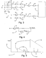
Fig. 1 is schematic arrangement of an audio/video system; -
Fig. 2 is a flow diagram; -
Fig. 3 is a signal cross-correlation circuit; -
Fig. 4 provides more detail for the peak detector block ofFig. 3 ; -
Fig. 5 is a graph demonstrating the detected peaks in a signal; and -
Fig. 6 is another example of an audio/video system. - Many consumers choose to add a supplemental audio system for use with their video display (e.g. a TV) to provide enhanced audio reproduction while watching a video program on their video display. The disclosure below discusses how to automatically switch the highest quality audio signal to the supplemental speaker system when AN sources (e.g. DVD player, cable box) are directly connected to the TV.
-
Fig. 1 discloses an audio/video system 60 which includes avideo display device 62 such as a liquid crystal or plasma display. Thedisplay 62 includes integrated speakers (acoustic drivers) 63 and an infra-red (IR)receiver 67. A pair of audio/video source devices, such as acable box 68 and a digital video disc (DVD)player 70, are attached to thedisplay 62 by, for example,respective HDMI cables display 62. Any of the AN source devices can be connected to thedisplay 62 by an analog connection (e.g. component video with a separate audio connection) instead of a digital connection (e.g. HDMI). The A/V source devices can each supply audio (e.g. Dolby Digital 5.1 with six channels) and video information to thedisplay 62. Another example of an A/V device that can be connected to thedisplay 62 is a computer (not shown). Thedisplay 62 can also be connected directly to the internet which can supply AN information to the display for presentation. Use is made of a source switching capability included in thedisplay 62 to select AV information fromAN device IR receiver 67 to select the desired AN information fromdevice display 62. Alternatively, the user can operate buttons on thedisplay 62 to select the desiredAN device - The display outputs an audio signal over a
cable 66 to anaudio receiver 64. The information in the output audio signal was supplied to thedisplay 62 by the selected A/V device cable 66 is a digital audio cable (such as optical or coaxial digital audio), then the output audio signal is in digital form (likely a PCM 2.0 signal). Ifcable 66 is a traditional stereo audio cable pair, then the audio signal output bydisplay 62 is in analog form. The output audio signal is transmitted overcable 66 and received by acontroller 61 in anaudio receiver 64. Thecontroller 61 is also connected to and can receive respective digital audio signals from thecable box 68 andDVD player 70 over respectivedigital audio cables controller 61 by each of thecable box 68 and theDVD player 70 would typically be a high quality, multichannel digital audio signal (e.g. a Dolby Digital 5.1 audio signal). These high quality digital audio signals can provide a higher quality acoustic performance than the audio signal output by thedisplay 62 overcable 66 because the latter is usually down-mixed. The reason thedisplay 62 down-mixes the received audio signals is to optimize the audio output from theintegrated speakers 63.Speakers 63 typically have significantly reduced performance as compared to an external audio system, and therefore the downmixed signals are sometimes greatly reduced in dynamic range and spectral extension. This downmixed signal cannot provide the dynamic range and bass performance that can be provided by the high quality digital audio signals provided directly from theAV sources - A
supplemental speaker system 76 is connected to thecontroller 61 of theaudio receiver 64 by acable 78. Thespeaker system 76 may have only a single acoustic driver (mono audio), or it may have multiple acoustic drivers arranged in, for example, a stereo, 5.1 or 7.2 audio system. A 5.1 system has the following speakers: left front, center, right front, left surround, right surround and bass (low frequency effects). The speaker system could also be a 1.0 or 1.1 type of system which is sometimes referred to as a "soundbar" (with or without a separate bass speaker). The speaker system preferably includes audio processing (such as a digital signal processor) and one or more power amplifiers As such, in an alternative example (not shown) theaudio receiver 64 and thesupplemental speaker system 76 can be combined into a single unit in which the functions of thecontroller 61 are performed by the audio processor of thespeaker system 76. This type of arrangement can result in reduced costs for the entire system. - Referring now to
Figs.1 and2 , the logic used by thecontroller 61 to provide the best available audio signal to thesupplemental speaker system 76 will be described. Once theaudio receiver 64 is powered up, the subroutine inFig. 2 starts at astep 90. At astep 92 thecontroller 61 checks to see if it is receiving an audio signal from thedisplay 62 over thecable 66. When a signal is being received, thecontroller 61 decodes and processes this signal as required and passes it to thespeaker system 76 overcable 78 at astep 94. This step provides audio output while thecontroller 61 is checking to see if there is a higher quality (multi-channel) audio signal available directly from the AN sources 68 and 70. At astep 96 thecontroller 61 checks to see if the received audio signal oncable 66 contains greater than two channels. When the signal oncable 66 is greater than two channels, this signal is continued to be processed and sent to thespeaker system 76 as it is a multi-channel signal. If the received audio signal fromcable 66 is a mono or two channel signal, thencontroller 61 compares this signal with the respective digital audio signals, if any, being received fromcables 80 and 82 (and decoded) to look for a match between the signal oncable 66 and one of the signals oncables 80 and 82 (step 98). In other words, thecontroller 61 determines if the audio program oncable 66 is substantially similar to any of the audio programs oncables cable 66 does not match any of the signals oncables cable 66 is continued to be processed and sent to thespeaker system 76. - The matching of signals described at the end of the previous paragraph can be done as follows. The
controller 61 looks for matching characteristics between the signal oncable 66 and each of the signals oncables cable 66 and the multi-channel signals which may be present on each ofcables cable 66, if digital, will likely (a) not include a low frequency effects (LFE) channel, (b) have experienced dynamic range compression, and (c) have been down-mixed from a multi-channel signal to a two channel or mono signal. The effects of down-mixing can be compensated for by calculating the acoustic energy sum over all channels for each signal being compared (down-mixing is approximately energy conserving). The short term spectrum of the energy sum for each signal is compared. The likely absence of a LFE channel in the signal oncable 66 can be compensated for by ignoring frequency content below 120Hz in the signals oncables cable 66 can be compensated for by evaluating the positions in time of energy changes and not the energy changes themselves. - When the audio program on
cable 66 substantially matches the audio program on one ofcables controller 61 transitions (e.g. by cross-fading) the audio signal output to thesupplemental audio system 76 overcable 78 from the signal oncable 66 to the matched signal oncable 80 or 82 (step 100). This transition from a "search phase" to a "matched phase" may take a relatively long amount of time as the audio signal oncable 66 should be properly paired with the video being presented on thedisplay 62. In other words, thecontroller 61 does not have to be very fast at detecting a match between the signal oncable 66 and one of the signals oncables cable 66 in the meantime with confidence that the video and audio being played will match. Care should be taken during this transition to minimize or eliminate any switching audio artifacts (e.g. popping). The energy sum over all channels for each signal (mentioned in the previous paragraph) can be used to match the loudness between the audio signal (stream) oncable 66 and the audio signal (stream) oncable cable 66 and the audio signal oncable controller 61 to time align the two audio signals before making the transition. - At a
step 102 thecontroller 61 checks to see if the audio signal being received oncable 66 still matches the same signal oncable step 92. This subroutine continues to run until the audio receiver is powered down. This transition from the matched phase to the search phase (moving fromstep 102 to step 94) should occur relatively quickly. Typically, this transition is caused by an A/V source switch by a user of the A/V system 60 (e.g. switching from thecable box 68 to the DVD player 70). In order to keep the video and audio matched, the transition back to using the audio signal on cable 66 (back to step 94) for rendering audio should occur as quickly as possible to minimize the amount of time that the video and audio do not match.. - The two matching audio streams on
cable 66 and one ofcables IR sensor 65. When IR activity is observed by thesensor 65, the system assumes an A/V source switch may be taking place and increases the threshold for audio signal matching. The system lowers this threshold when no IR remote signal is present. - Another way to describe the example shown in
Figures 1 and2 is as follows. Thereceiver 64 receives a digital audio signal over one ofcables video source devices video display device 62 overrespective cables receiver 64 receives an indication from thevideo display device 62 that the digital audio signal should be transmitted to asupplemental audio system 76. This indication is the audio signal that thereceiver 64 receives overcable 66 from thedisplay 62. When the audio signal oncable 66 and the digital audio signal substantially match, the digital audio signal is output to the supplemental audio system over acable 78. - Referring now to
Figs. 3-5 , an example of how to compare a signal oncable 66 with a signal oncable receiver 64. InFig. 3 , a 5.1channel signal 103 received overcable 80 includes the following components: L, Ls, C, Rs, R and LFE. The LFE (low frequency effects) signal 104 is discarded. The Ls, C and Rs are each passed throughrespective amplifiers 106 which each apply a 0.7 gain to their input signal. The L, Ls and C signals are then passed to asummer 110 while the C, Rs and R signals are passed to asummer 112. The signals out ofsummers bandpass filters filters blocks blocks summer 122. The signal out ofsummer 122 has a square root function applied to it inblock 124, and then a peak detector 126 (described in further detail below) operates on the signal. Finally, the signal out of thepeak detector 126 is passed to a sparse cross-correlation block 128 (described in further detail below). It should be noted that a signal on cable 82 (Fig. 1 ) would receive similar signal processing as that described in this paragraph in a separate signal path (not shown) before being fed intoblock 128. - A two
channel stereo signal 130 received overcable 66 includes the following components: Lt and Rt. The Lt and Rt signals are respectively passed tobandpass filters filters blocks blocks summer 140. The signal out ofsummer 140 has a square root function applied to it inblock 142, and then a peak detector 144 (described in further detail below) operates on the signal. Finally, the signal out of thepeak detector 144 is passed to the sparse cross-correlation block 128 (described in further detail below). - With reference to
Figs. 3 and 4 , each of thepeak detectors Fig. 4 apeak detector 126 is shown. A signal X(t) that is fed into thepeak detector 126 is first low pass filtered at ablock 146. This low pass filter is a 2nd order Butterworth filter with a cutoff of about 1 kHz. The signal out of thefilter 146 is given as XLPF(t). Then XLPF(t) is differentiated at ablock 148 to obtain XLPF(t). Anywhere that Ẋ LPF(t) crosses zero by going from a positive number to a negative number corresponds to a peak in XLPF(t) (by definition of a derivative).As such, these zero crossings are used to locate the peaks of XLPF(t). The zero crossings or peaks as a function of time are determined in ablock 150. The output ofblock 150 is used to control the transmission of XLPF(t). When a peak is detected, XLPF(t) is transmitted. When a peak is not detected, a stream of zeros is transmitted. This transmission of zeros and XLPF(t) results in XPEAK(t). - Turning to
Fig. 5 , in order to reduce the amount of data that needs to be processed, insignificant peaks are discarded. Agraph 152 includes a "t" axis (time) 154 and an XPEAK(t)axis 156. The signal at this point is equal to themaximum points 158 of XLPF(t) at certain locations and zero everywhere else. Any small peaks that are preceded by large peaks are discarded. This is accomplished by using an exponentially decayingthreshold 160. Whenever a peak is detected, the threshold is reset to that peak value. The threshold is then allowed to decay until another peak is found that exceeds the threshold. In this example the first three peaks from left to right are utilized because they are not less than thethreshold 160. The last two peaks from left to right are discarded because they are less than thethreshold 160. - Referring to
Figs. 3 and 5 , thesparse cross-correlation block 128 utilizes an algorithm that receives from thepeak detector 126 or 144 a sequence of numbers that correspond to the non-discarded peak values and locations (in time). The algorithm inblock 128 uses this information to estimate the correlation between thestereo audio signal 130 oncable 66 and any multi-channel audio signal which may be present oncables 80 and 82 (Fig. 1 ). - The next step in the
block 128 algorithm is normalization. Each frame of data received is made to have unit energy (i.e. Xnorm = Xpeaks ÷ ||Xpeaks||), where ||Xpeaks|| is the energy of Xpeaks i.e., it is the square root of the sum of the squares of Xpeaks found in a 100 milliseconds (ms) sample of the signal (called a frame of data). At this point in theblock 128 algorithm, a multichannel audio signal oncable cable 66 if the multichannel signal has (a) less than half the energy of the stereo signal, or (b) more than ten times the energy of the stereo signal. If a multi-channel audio signal is still a possible match with the stereo audio signal after normalization, the cross-correlation of the signals is approximated. Let Y[n] and X[n] be sampled data signals, where N is sample number. A cross-correlation is typically computed as:
- At this point, however, there are no time sequences: only the peak values and peak locations are known, so we cannot perform the cross-correlation as it is typically done and must approximate it using only the peak values and peak locations. The benefit is that this greatly reduces the amount of computation that is needed. The cross-correlation of the multichannel signal and stereo signal is approximated as follows.
-
- X51
- = peak values of a 5.1 (multichannel source) Mpeaks
- XLR
- = peak values of a stereo audio source from a display N peaks
- τ 51
- = time locations of peaks of a 5.1 source
- τ LR
- = time locations of peaks of a stereo audio source
- The convolution equation given above can be approximated as follows. First, compute all the cross-product terms by computing the outer product of the two vectors of peak values

- Next, compute the time alignment value of each of the entries in the cross-product matrix above,

- 1. Next, the entries of the above time alignment matrix are rounded so that the product terms that are within about 1 ms of each other are considered to be collocated.
- 2. Product terms that have the same time alignment are added together to create an approximation to the cross-correlation. If the peak of this cross-correlation is greater than 0.75 then the multichannel signal and stereo signal are considered to be matched for that frame.
- If the
controller 61 is currently sending the signal fromcable 66 to thespeaker system 76, thecontroller 61 will switch to sending the multichannel signal fromcable speaker system 76 if at least nine out of ten frames are considered to be matched (cross-correlated). If thecontroller 61 is currently sending a multichannel signal fromcable speaker system 76, thecontroller 61 will switch to sending the signal fromcable 66 to thespeaker system 76 if less than two out of ten frames are considered to be matched (cross-correlated). - In order for the signal matching described above with reference to
Figs. 3-5 to work well, the peaks extracted from the multichannel signal one.g. cable 80 and the stereo signal oncable 66 should be time-aligned within about 100 ms. Typically the time delays are larger than this and it is necessary to estimate the time delays in parallel to the matching algorithm and adjust the time delays accordingly. This can be don by running a separate cross-correlation algorithm similar to the one discussed above is on a much larger frame size (e.g. about 1 second) to estimate the time alignment of the multichannel and stereo signals. The results of this time alignment determination set the delay values of variable time delay for the leading signal prior to being send to signal comparison block. - Turning to
Fig. 4 , another example will be described. Components inFig. 4 that are similar to like components inFig. 1 are given the same reference numerals as inFig. 1 .Fig. 4 discloses an audio/video system 60 which includes avideo display device 62 that includes integrated speakers (acoustic drivers) 63 and an infra-red (IR)receiver 67. A pair of audio/video source devices, such as acable box 68 and a digital video disc (DVD)player 70, are attached to anaudio receiver 64 by, for example,respective HDMI cables receiver 64 which includes video and audio information. Acontroller 61 in thereceiver 64 receives the signals fromcables respective cables display 62. In other words, the video information oncable 81 is passed overcable 72, and the video information oncable 83 is passed overcable 74. Use is made of a source switching capability included in thedisplay 62 to select video information from A/V device IR receiver 67 to select the desired video information fromdevice display 62. Alternatively, the user can operate buttons on thedisplay 62 to select the desired A/V device - Assume the user makes a selection of video information on
cable 72 to present on the display 62 (a video sink). Thedisplay 62 and receiver 64 (a video repeater) will go through an HDCP "handshake" overHDMI cable 72. Thecontroller 61 checks to see if it is receiving an audio signal from thedisplay 62 over thecable 66. The subroutine shown inFig. 2 and described above is then followed. Accordingly, thecontroller 61 takes audio information that it has received overcable 81 and passes the audio information to thesupplemental audio system 76 overcable 78. In this way the audio is automatically switched tosupplemental audio system 76 so that it matches the video that is being presented on thedisplay 62. - Another way to describe the example shown in
Fig. 4 is as follows. Thereceiver 64 receives a digital audio signal over one ofcables video source devices video display device 62 overrespective cables receiver 64 receives an indication from thevideo display device 62 overcable 66 that the digital audio signal should be transmitted to asupplemental audio system 76. The digital audio signal is output to the supplemental audio system over acable 78.
Claims (15)
- A method for automatically switching an audio source, comprising the steps of:receiving an audio signal from a video display device (62);receiving a digital audio signal from one of a plurality of audio/video source devices (68;70) which each can supply audio and video information to the video display device;comparing the digital audio signal with the audio signal from the video display device, by looking for a match between them; andoutputting the digital audio signal to a supplemental audio system (76) of the video display device when the comparing step indicates that the digital audio signal and the audio signal from the video display device contain substantially similar audio programs, and outputting the audio signal to the supplemental audio system otherwise.
- The method of claim 1, wherein the audio signal received from the video display device (62) is an analog signal.
- The method of claim 1, wherein the audio signal received from the video display device (62) is a digital signal.
- The method of claim 1, wherein the audio signal received from the video display device (62) is supplied to the video display device from one of the audio/video source devices (68;70).
- The method of claim 1, wherein the digital audio signal received from the source device has 6 or more channels.
- The method of claim 1, wherein the digital audio signal received from the source device has more channels than the audio signal received from the video display device (62).
- The method of claim 1, wherein the receiving step includes receiving a digital audio signal from each of the plurality of audio/video source devices (68;70).
- The method of claim 1, wherein the comparing step utilizes information beyond what is included in the audio signal and digital audio signal.
- The method of claim 8, wherein the information that is beyond what is included in the audio signal and digital audio signal includes the presence or absence of a wireless signal from a remote control.
- An apparatus for automatically switching an audio source, comprising:an audio receiver (64) that is arranged for receiving (a) an audio signal from a video display device (62), and (b) a digital audio signal from one of a plurality of audio/video source devices (68;70) which each can supply audio and video information to the video display device, wherein the audio receiver is further arranged for comparing the digital audio signal with the audio signal from the video display device by looking for a match between them, for outputting the digital audio signal to a supplemental audio system (76) of the video display device when the digital audio signal and the audio signal from the video display device contain substantially similar audio programs, and for outputting the audio signal to the supplemental audio system otherwise.
- The apparatus of claim 10, wherein the audio signal received from the video display device (62) is an analog signal.
- The apparatus of claim 10, wherein the video display device (62) is a television.
- The apparatus of claim 10, wherein the audio signal received from the video display device (62) is supplied to the video display device from one of the audio/video source devices (68;70).
- The apparatus of claim 10, wherein the digital audio signal received from the source device has 5 or more channels.
- The apparatus of claim 10, wherein the digital audio signal received from the source device has more channels than the audio signal received from the video display device (62).
Applications Claiming Priority (2)
| Application Number | Priority Date | Filing Date | Title |
|---|---|---|---|
| US12/727,595 US9426574B2 (en) | 2010-03-19 | 2010-03-19 | Automatic audio source switching |
| PCT/US2011/027382 WO2011115766A1 (en) | 2010-03-19 | 2011-03-07 | Automatic audio source switching |
Publications (2)
| Publication Number | Publication Date |
|---|---|
| EP2548379A1 EP2548379A1 (en) | 2013-01-23 |
| EP2548379B1 true EP2548379B1 (en) | 2016-10-05 |
Family
ID=44022909
Family Applications (1)
| Application Number | Title | Priority Date | Filing Date |
|---|---|---|---|
| EP11709556.2A Active EP2548379B1 (en) | 2010-03-19 | 2011-03-07 | Automatic audio source switching |
Country Status (3)
| Country | Link |
|---|---|
| US (1) | US9426574B2 (en) |
| EP (1) | EP2548379B1 (en) |
| WO (1) | WO2011115766A1 (en) |
Families Citing this family (38)
| Publication number | Priority date | Publication date | Assignee | Title |
|---|---|---|---|---|
| US11650784B2 (en) | 2003-07-28 | 2023-05-16 | Sonos, Inc. | Adjusting volume levels |
| US11294618B2 (en) | 2003-07-28 | 2022-04-05 | Sonos, Inc. | Media player system |
| US8020023B2 (en) | 2003-07-28 | 2011-09-13 | Sonos, Inc. | Systems and methods for synchronizing operations among a plurality of independently clocked digital data processing devices without a voltage controlled crystal oscillator |
| US8234395B2 (en) | 2003-07-28 | 2012-07-31 | Sonos, Inc. | System and method for synchronizing operations among a plurality of independently clocked digital data processing devices |
| US11106425B2 (en) | 2003-07-28 | 2021-08-31 | Sonos, Inc. | Synchronizing operations among a plurality of independently clocked digital data processing devices |
| US11106424B2 (en) | 2003-07-28 | 2021-08-31 | Sonos, Inc. | Synchronizing operations among a plurality of independently clocked digital data processing devices |
| US8086752B2 (en) | 2006-11-22 | 2011-12-27 | Sonos, Inc. | Systems and methods for synchronizing operations among a plurality of independently clocked digital data processing devices that independently source digital data |
| US10613817B2 (en) | 2003-07-28 | 2020-04-07 | Sonos, Inc. | Method and apparatus for displaying a list of tracks scheduled for playback by a synchrony group |
| US8290603B1 (en) | 2004-06-05 | 2012-10-16 | Sonos, Inc. | User interfaces for controlling and manipulating groupings in a multi-zone media system |
| US9374607B2 (en) | 2012-06-26 | 2016-06-21 | Sonos, Inc. | Media playback system with guest access |
| US9977561B2 (en) | 2004-04-01 | 2018-05-22 | Sonos, Inc. | Systems, methods, apparatus, and articles of manufacture to provide guest access |
| US8326951B1 (en) | 2004-06-05 | 2012-12-04 | Sonos, Inc. | Establishing a secure wireless network with minimum human intervention |
| US8868698B2 (en) | 2004-06-05 | 2014-10-21 | Sonos, Inc. | Establishing a secure wireless network with minimum human intervention |
| US9202509B2 (en) | 2006-09-12 | 2015-12-01 | Sonos, Inc. | Controlling and grouping in a multi-zone media system |
| US8788080B1 (en) | 2006-09-12 | 2014-07-22 | Sonos, Inc. | Multi-channel pairing in a media system |
| US12167216B2 (en) | 2006-09-12 | 2024-12-10 | Sonos, Inc. | Playback device pairing |
| US8483853B1 (en) | 2006-09-12 | 2013-07-09 | Sonos, Inc. | Controlling and manipulating groupings in a multi-zone media system |
| US11429343B2 (en) | 2011-01-25 | 2022-08-30 | Sonos, Inc. | Stereo playback configuration and control |
| US11265652B2 (en) | 2011-01-25 | 2022-03-01 | Sonos, Inc. | Playback device pairing |
| US8938312B2 (en) | 2011-04-18 | 2015-01-20 | Sonos, Inc. | Smart line-in processing |
| US9042556B2 (en) | 2011-07-19 | 2015-05-26 | Sonos, Inc | Shaping sound responsive to speaker orientation |
| US9286384B2 (en) | 2011-09-21 | 2016-03-15 | Sonos, Inc. | Methods and systems to share media |
| US8971546B2 (en) | 2011-10-14 | 2015-03-03 | Sonos, Inc. | Systems, methods, apparatus, and articles of manufacture to control audio playback devices |
| US9344292B2 (en) | 2011-12-30 | 2016-05-17 | Sonos, Inc. | Systems and methods for player setup room names |
| US9729115B2 (en) | 2012-04-27 | 2017-08-08 | Sonos, Inc. | Intelligently increasing the sound level of player |
| KR20130137905A (en) * | 2012-06-08 | 2013-12-18 | 삼성전자주식회사 | Audio output apparatus and method for outputting audio |
| US9008330B2 (en) | 2012-09-28 | 2015-04-14 | Sonos, Inc. | Crossover frequency adjustments for audio speakers |
| US9826320B2 (en) * | 2013-05-15 | 2017-11-21 | Gn Hearing A/S | Hearing device and a method for receiving wireless audio streaming |
| US9226087B2 (en) | 2014-02-06 | 2015-12-29 | Sonos, Inc. | Audio output balancing during synchronized playback |
| US9226073B2 (en) | 2014-02-06 | 2015-12-29 | Sonos, Inc. | Audio output balancing during synchronized playback |
| US10248376B2 (en) | 2015-06-11 | 2019-04-02 | Sonos, Inc. | Multiple groupings in a playback system |
| CN105141997B (en) * | 2015-08-18 | 2018-09-04 | 京东方科技集团股份有限公司 | Display device, remote control, display system and program push method |
| US10098082B2 (en) | 2015-12-16 | 2018-10-09 | Sonos, Inc. | Synchronization of content between networked devices |
| US10303422B1 (en) | 2016-01-05 | 2019-05-28 | Sonos, Inc. | Multiple-device setup |
| GB2549810B (en) * | 2016-04-29 | 2020-08-19 | Cirrus Logic Int Semiconductor Ltd | Audio signal processing |
| US9967689B1 (en) | 2016-09-29 | 2018-05-08 | Sonos, Inc. | Conditional content enhancement |
| US10712997B2 (en) | 2016-10-17 | 2020-07-14 | Sonos, Inc. | Room association based on name |
| EP4672764A3 (en) | 2020-09-25 | 2026-01-21 | Sonos, Inc. | Intelligent setup for playback devices |
Family Cites Families (19)
| Publication number | Priority date | Publication date | Assignee | Title |
|---|---|---|---|---|
| DE3036552C2 (en) * | 1980-09-27 | 1985-04-25 | Blaupunkt-Werke Gmbh, 3200 Hildesheim | Television reception system |
| US4625235A (en) * | 1983-05-19 | 1986-11-25 | Westinghouse Electric Corp. | Remote control switching of television sources |
| US8539528B2 (en) * | 1995-04-17 | 2013-09-17 | Starsight Telecast, Inc. | Multi-source switching in a television system |
| EP0866638B1 (en) | 1997-03-10 | 2011-06-15 | Panasonic Corporation | Audiovisual amplifier |
| US6052471A (en) * | 1998-05-08 | 2000-04-18 | Sony Corporation | Smart audio receiver that automatically select an input audio source |
| GB9911879D0 (en) * | 1999-05-22 | 1999-07-21 | Koninkl Philips Electronics Nv | Home entertainment system audio handling |
| KR20010016704A (en) * | 1999-08-02 | 2001-03-05 | 구자홍 | apparatus for selecting input signal in digital TV |
| US20020131611A1 (en) * | 2001-03-13 | 2002-09-19 | Hoover Alan Anderson | `Audio surround sound power management switching |
| US20030108227A1 (en) * | 2001-12-11 | 2003-06-12 | Koninklijke Philips Electronics N.V. | Remote control with the fingerprint recognition capability |
| US8150683B2 (en) | 2003-11-04 | 2012-04-03 | Stmicroelectronics Asia Pacific Pte., Ltd. | Apparatus, method, and computer program for comparing audio signals |
| CN1914595A (en) * | 2004-02-02 | 2007-02-14 | 皇家飞利浦电子股份有限公司 | Delegating skinning service for CE apparatus GUI to the internet |
| JP2008510335A (en) * | 2004-08-12 | 2008-04-03 | コーニンクレッカ フィリップス エレクトロニクス エヌ ヴィ | Sound source selection |
| JP4674474B2 (en) | 2005-02-24 | 2011-04-20 | パナソニック株式会社 | Parallel drive bi-amp switching circuit |
| DE102005014477A1 (en) * | 2005-03-30 | 2006-10-12 | Fraunhofer-Gesellschaft zur Förderung der angewandten Forschung e.V. | Apparatus and method for generating a data stream and generating a multi-channel representation |
| JP4577074B2 (en) | 2005-04-13 | 2010-11-10 | 日本電気株式会社 | Selective receiving method and receiving apparatus |
| JP4432858B2 (en) * | 2005-07-29 | 2010-03-17 | ソニー株式会社 | Broadcast reception method |
| EP1761110A1 (en) * | 2005-09-02 | 2007-03-07 | Ecole Polytechnique Fédérale de Lausanne | Method to generate multi-channel audio signals from stereo signals |
| US8421597B2 (en) * | 2005-10-14 | 2013-04-16 | Kyocera Corporation | Remote control apparatus and portable communication terminal |
| EP1947843A4 (en) * | 2005-10-31 | 2010-07-07 | Panasonic Corp | AUDIOVISUAL SYSTEM |
-
2010
- 2010-03-19 US US12/727,595 patent/US9426574B2/en active Active
-
2011
- 2011-03-07 WO PCT/US2011/027382 patent/WO2011115766A1/en not_active Ceased
- 2011-03-07 EP EP11709556.2A patent/EP2548379B1/en active Active
Non-Patent Citations (1)
| Title |
|---|
| None * |
Also Published As
| Publication number | Publication date |
|---|---|
| US9426574B2 (en) | 2016-08-23 |
| US20110228944A1 (en) | 2011-09-22 |
| WO2011115766A1 (en) | 2011-09-22 |
| EP2548379A1 (en) | 2013-01-23 |
Similar Documents
| Publication | Publication Date | Title |
|---|---|---|
| US9426574B2 (en) | Automatic audio source switching | |
| US10362422B2 (en) | Audio device | |
| CA2680328C (en) | A method and an apparatus for processing an audio signal | |
| RU2559713C2 (en) | Spatial reproduction of sound | |
| CN100518269C (en) | Audio level control device and method | |
| US9747923B2 (en) | Voice audio rendering augmentation | |
| US6867820B2 (en) | Method for displaying audio settings menu of display apparatus | |
| KR20120131210A (en) | Apparatus and method for generating audio output signals using object based metadata | |
| US11564050B2 (en) | Audio output apparatus and method of controlling thereof | |
| US7212253B1 (en) | Home entertainment system audio handling | |
| EP3734998A1 (en) | Method and apparatus for adaptive control of decorrelation filters | |
| US20070276524A1 (en) | Digital Sound Signal Processing Apparatus | |
| EP4662657A1 (en) | Dialog intelligibility enhancement method and system | |
| KR20070041567A (en) | Select audio source | |
| US20100091189A1 (en) | Audio Signal Processing Device and Audio Signal Processing Method | |
| JP2009159020A (en) | Signal processing apparatus, signal processing method, and program | |
| JP2009283997A (en) | Voice output device, program, and recording medium | |
| JP2006050241A (en) | Decryption device | |
| KR102531634B1 (en) | Audio apparatus and method of controlling the same | |
| US20220329957A1 (en) | Audio signal processing method and audio signal processing apparatus | |
| JP2004241853A (en) | Audio signal processing apparatus | |
| WO2026085066A1 (en) | Enhanced dialogue rendering | |
| JP2012156598A (en) | Video/audio output device | |
| KR20080085297A (en) | Multi-channel audio system, audio output method thereof, audio output method of TV receiver | |
| KR20130079895A (en) | Decoding method of audio signal and decoding apparatus thereof |
Legal Events
| Date | Code | Title | Description |
|---|---|---|---|
| PUAI | Public reference made under article 153(3) epc to a published international application that has entered the european phase |
Free format text: ORIGINAL CODE: 0009012 |
|
| 17P | Request for examination filed |
Effective date: 20121004 |
|
| AK | Designated contracting states |
Kind code of ref document: A1 Designated state(s): AL AT BE BG CH CY CZ DE DK EE ES FI FR GB GR HR HU IE IS IT LI LT LU LV MC MK MT NL NO PL PT RO RS SE SI SK SM TR |
|
| DAX | Request for extension of the european patent (deleted) | ||
| REG | Reference to a national code |
Ref country code: DE Ref legal event code: R079 Ref document number: 602011030929 Country of ref document: DE Free format text: PREVIOUS MAIN CLASS: H04R0005040000 Ipc: H04N0007088000 |
|
| GRAP | Despatch of communication of intention to grant a patent |
Free format text: ORIGINAL CODE: EPIDOSNIGR1 |
|
| RIC1 | Information provided on ipc code assigned before grant |
Ipc: G06F 3/16 20060101ALI20160622BHEP Ipc: H04N 21/4363 20110101ALI20160622BHEP Ipc: H04N 7/088 20060101AFI20160622BHEP Ipc: H04N 5/60 20060101ALI20160622BHEP Ipc: H04R 5/04 20060101ALI20160622BHEP Ipc: H04N 5/445 20060101ALI20160622BHEP Ipc: G08C 23/04 20060101ALI20160622BHEP |
|
| INTG | Intention to grant announced |
Effective date: 20160714 |
|
| GRAS | Grant fee paid |
Free format text: ORIGINAL CODE: EPIDOSNIGR3 |
|
| GRAA | (expected) grant |
Free format text: ORIGINAL CODE: 0009210 |
|
| AK | Designated contracting states |
Kind code of ref document: B1 Designated state(s): AL AT BE BG CH CY CZ DE DK EE ES FI FR GB GR HR HU IE IS IT LI LT LU LV MC MK MT NL NO PL PT RO RS SE SI SK SM TR |
|
| REG | Reference to a national code |
Ref country code: GB Ref legal event code: FG4D |
|
| REG | Reference to a national code |
Ref country code: CH Ref legal event code: EP |
|
| REG | Reference to a national code |
Ref country code: AT Ref legal event code: REF Ref document number: 835483 Country of ref document: AT Kind code of ref document: T Effective date: 20161015 |
|
| REG | Reference to a national code |
Ref country code: IE Ref legal event code: FG4D |
|
| REG | Reference to a national code |
Ref country code: DE Ref legal event code: R096 Ref document number: 602011030929 Country of ref document: DE |
|
| REG | Reference to a national code |
Ref country code: NL Ref legal event code: MP Effective date: 20161005 |
|
| REG | Reference to a national code |
Ref country code: LT Ref legal event code: MG4D |
|
| PG25 | Lapsed in a contracting state [announced via postgrant information from national office to epo] |
Ref country code: LV Free format text: LAPSE BECAUSE OF FAILURE TO SUBMIT A TRANSLATION OF THE DESCRIPTION OR TO PAY THE FEE WITHIN THE PRESCRIBED TIME-LIMIT Effective date: 20161005 |
|
| REG | Reference to a national code |
Ref country code: AT Ref legal event code: MK05 Ref document number: 835483 Country of ref document: AT Kind code of ref document: T Effective date: 20161005 |
|
| REG | Reference to a national code |
Ref country code: FR Ref legal event code: PLFP Year of fee payment: 7 |
|
| PG25 | Lapsed in a contracting state [announced via postgrant information from national office to epo] |
Ref country code: LT Free format text: LAPSE BECAUSE OF FAILURE TO SUBMIT A TRANSLATION OF THE DESCRIPTION OR TO PAY THE FEE WITHIN THE PRESCRIBED TIME-LIMIT Effective date: 20161005 Ref country code: NO Free format text: LAPSE BECAUSE OF FAILURE TO SUBMIT A TRANSLATION OF THE DESCRIPTION OR TO PAY THE FEE WITHIN THE PRESCRIBED TIME-LIMIT Effective date: 20170105 Ref country code: SE Free format text: LAPSE BECAUSE OF FAILURE TO SUBMIT A TRANSLATION OF THE DESCRIPTION OR TO PAY THE FEE WITHIN THE PRESCRIBED TIME-LIMIT Effective date: 20161005 Ref country code: GR Free format text: LAPSE BECAUSE OF FAILURE TO SUBMIT A TRANSLATION OF THE DESCRIPTION OR TO PAY THE FEE WITHIN THE PRESCRIBED TIME-LIMIT Effective date: 20170106 |
|
| PGFP | Annual fee paid to national office [announced via postgrant information from national office to epo] |
Ref country code: FR Payment date: 20170327 Year of fee payment: 7 |
|
| PG25 | Lapsed in a contracting state [announced via postgrant information from national office to epo] |
Ref country code: NL Free format text: LAPSE BECAUSE OF FAILURE TO SUBMIT A TRANSLATION OF THE DESCRIPTION OR TO PAY THE FEE WITHIN THE PRESCRIBED TIME-LIMIT Effective date: 20161005 Ref country code: IS Free format text: LAPSE BECAUSE OF FAILURE TO SUBMIT A TRANSLATION OF THE DESCRIPTION OR TO PAY THE FEE WITHIN THE PRESCRIBED TIME-LIMIT Effective date: 20170205 Ref country code: ES Free format text: LAPSE BECAUSE OF FAILURE TO SUBMIT A TRANSLATION OF THE DESCRIPTION OR TO PAY THE FEE WITHIN THE PRESCRIBED TIME-LIMIT Effective date: 20161005 Ref country code: PL Free format text: LAPSE BECAUSE OF FAILURE TO SUBMIT A TRANSLATION OF THE DESCRIPTION OR TO PAY THE FEE WITHIN THE PRESCRIBED TIME-LIMIT Effective date: 20161005 Ref country code: HR Free format text: LAPSE BECAUSE OF FAILURE TO SUBMIT A TRANSLATION OF THE DESCRIPTION OR TO PAY THE FEE WITHIN THE PRESCRIBED TIME-LIMIT Effective date: 20161005 Ref country code: AT Free format text: LAPSE BECAUSE OF FAILURE TO SUBMIT A TRANSLATION OF THE DESCRIPTION OR TO PAY THE FEE WITHIN THE PRESCRIBED TIME-LIMIT Effective date: 20161005 Ref country code: PT Free format text: LAPSE BECAUSE OF FAILURE TO SUBMIT A TRANSLATION OF THE DESCRIPTION OR TO PAY THE FEE WITHIN THE PRESCRIBED TIME-LIMIT Effective date: 20170206 Ref country code: BE Free format text: LAPSE BECAUSE OF FAILURE TO SUBMIT A TRANSLATION OF THE DESCRIPTION OR TO PAY THE FEE WITHIN THE PRESCRIBED TIME-LIMIT Effective date: 20161005 Ref country code: RS Free format text: LAPSE BECAUSE OF FAILURE TO SUBMIT A TRANSLATION OF THE DESCRIPTION OR TO PAY THE FEE WITHIN THE PRESCRIBED TIME-LIMIT Effective date: 20161005 Ref country code: FI Free format text: LAPSE BECAUSE OF FAILURE TO SUBMIT A TRANSLATION OF THE DESCRIPTION OR TO PAY THE FEE WITHIN THE PRESCRIBED TIME-LIMIT Effective date: 20161005 |
|
| PGFP | Annual fee paid to national office [announced via postgrant information from national office to epo] |
Ref country code: GB Payment date: 20170327 Year of fee payment: 7 |
|
| REG | Reference to a national code |
Ref country code: DE Ref legal event code: R097 Ref document number: 602011030929 Country of ref document: DE |
|
| PG25 | Lapsed in a contracting state [announced via postgrant information from national office to epo] |
Ref country code: SK Free format text: LAPSE BECAUSE OF FAILURE TO SUBMIT A TRANSLATION OF THE DESCRIPTION OR TO PAY THE FEE WITHIN THE PRESCRIBED TIME-LIMIT Effective date: 20161005 Ref country code: EE Free format text: LAPSE BECAUSE OF FAILURE TO SUBMIT A TRANSLATION OF THE DESCRIPTION OR TO PAY THE FEE WITHIN THE PRESCRIBED TIME-LIMIT Effective date: 20161005 Ref country code: RO Free format text: LAPSE BECAUSE OF FAILURE TO SUBMIT A TRANSLATION OF THE DESCRIPTION OR TO PAY THE FEE WITHIN THE PRESCRIBED TIME-LIMIT Effective date: 20161005 Ref country code: DK Free format text: LAPSE BECAUSE OF FAILURE TO SUBMIT A TRANSLATION OF THE DESCRIPTION OR TO PAY THE FEE WITHIN THE PRESCRIBED TIME-LIMIT Effective date: 20161005 Ref country code: CZ Free format text: LAPSE BECAUSE OF FAILURE TO SUBMIT A TRANSLATION OF THE DESCRIPTION OR TO PAY THE FEE WITHIN THE PRESCRIBED TIME-LIMIT Effective date: 20161005 |
|
| PLBE | No opposition filed within time limit |
Free format text: ORIGINAL CODE: 0009261 |
|
| STAA | Information on the status of an ep patent application or granted ep patent |
Free format text: STATUS: NO OPPOSITION FILED WITHIN TIME LIMIT |
|
| PG25 | Lapsed in a contracting state [announced via postgrant information from national office to epo] |
Ref country code: BG Free format text: LAPSE BECAUSE OF FAILURE TO SUBMIT A TRANSLATION OF THE DESCRIPTION OR TO PAY THE FEE WITHIN THE PRESCRIBED TIME-LIMIT Effective date: 20170105 Ref country code: SM Free format text: LAPSE BECAUSE OF FAILURE TO SUBMIT A TRANSLATION OF THE DESCRIPTION OR TO PAY THE FEE WITHIN THE PRESCRIBED TIME-LIMIT Effective date: 20161005 Ref country code: IT Free format text: LAPSE BECAUSE OF FAILURE TO SUBMIT A TRANSLATION OF THE DESCRIPTION OR TO PAY THE FEE WITHIN THE PRESCRIBED TIME-LIMIT Effective date: 20161005 |
|
| 26N | No opposition filed |
Effective date: 20170706 |
|
| REG | Reference to a national code |
Ref country code: CH Ref legal event code: PL |
|
| PG25 | Lapsed in a contracting state [announced via postgrant information from national office to epo] |
Ref country code: MC Free format text: LAPSE BECAUSE OF FAILURE TO SUBMIT A TRANSLATION OF THE DESCRIPTION OR TO PAY THE FEE WITHIN THE PRESCRIBED TIME-LIMIT Effective date: 20161005 Ref country code: SI Free format text: LAPSE BECAUSE OF FAILURE TO SUBMIT A TRANSLATION OF THE DESCRIPTION OR TO PAY THE FEE WITHIN THE PRESCRIBED TIME-LIMIT Effective date: 20161005 |
|
| REG | Reference to a national code |
Ref country code: IE Ref legal event code: MM4A |
|
| PG25 | Lapsed in a contracting state [announced via postgrant information from national office to epo] |
Ref country code: LU Free format text: LAPSE BECAUSE OF NON-PAYMENT OF DUE FEES Effective date: 20170307 |
|
| PG25 | Lapsed in a contracting state [announced via postgrant information from national office to epo] |
Ref country code: LI Free format text: LAPSE BECAUSE OF NON-PAYMENT OF DUE FEES Effective date: 20170331 Ref country code: CH Free format text: LAPSE BECAUSE OF NON-PAYMENT OF DUE FEES Effective date: 20170331 Ref country code: IE Free format text: LAPSE BECAUSE OF NON-PAYMENT OF DUE FEES Effective date: 20170307 |
|
| PG25 | Lapsed in a contracting state [announced via postgrant information from national office to epo] |
Ref country code: MT Free format text: LAPSE BECAUSE OF NON-PAYMENT OF DUE FEES Effective date: 20170307 |
|
| GBPC | Gb: european patent ceased through non-payment of renewal fee |
Effective date: 20180307 |
|
| PG25 | Lapsed in a contracting state [announced via postgrant information from national office to epo] |
Ref country code: GB Free format text: LAPSE BECAUSE OF NON-PAYMENT OF DUE FEES Effective date: 20180307 |
|
| PG25 | Lapsed in a contracting state [announced via postgrant information from national office to epo] |
Ref country code: FR Free format text: LAPSE BECAUSE OF NON-PAYMENT OF DUE FEES Effective date: 20180331 |
|
| PG25 | Lapsed in a contracting state [announced via postgrant information from national office to epo] |
Ref country code: HU Free format text: LAPSE BECAUSE OF FAILURE TO SUBMIT A TRANSLATION OF THE DESCRIPTION OR TO PAY THE FEE WITHIN THE PRESCRIBED TIME-LIMIT; INVALID AB INITIO Effective date: 20110307 |
|
| PG25 | Lapsed in a contracting state [announced via postgrant information from national office to epo] |
Ref country code: CY Free format text: LAPSE BECAUSE OF NON-PAYMENT OF DUE FEES Effective date: 20161005 |
|
| PG25 | Lapsed in a contracting state [announced via postgrant information from national office to epo] |
Ref country code: MK Free format text: LAPSE BECAUSE OF FAILURE TO SUBMIT A TRANSLATION OF THE DESCRIPTION OR TO PAY THE FEE WITHIN THE PRESCRIBED TIME-LIMIT Effective date: 20161005 |
|
| PG25 | Lapsed in a contracting state [announced via postgrant information from national office to epo] |
Ref country code: TR Free format text: LAPSE BECAUSE OF FAILURE TO SUBMIT A TRANSLATION OF THE DESCRIPTION OR TO PAY THE FEE WITHIN THE PRESCRIBED TIME-LIMIT Effective date: 20161005 |
|
| PG25 | Lapsed in a contracting state [announced via postgrant information from national office to epo] |
Ref country code: AL Free format text: LAPSE BECAUSE OF FAILURE TO SUBMIT A TRANSLATION OF THE DESCRIPTION OR TO PAY THE FEE WITHIN THE PRESCRIBED TIME-LIMIT Effective date: 20161005 |
|
| PGFP | Annual fee paid to national office [announced via postgrant information from national office to epo] |
Ref country code: DE Payment date: 20260219 Year of fee payment: 16 |