EP2548055B1 - Module de mélange de lumière et luminaire le comportant - Google Patents
Module de mélange de lumière et luminaire le comportant Download PDFInfo
- Publication number
- EP2548055B1 EP2548055B1 EP11713078.1A EP11713078A EP2548055B1 EP 2548055 B1 EP2548055 B1 EP 2548055B1 EP 11713078 A EP11713078 A EP 11713078A EP 2548055 B1 EP2548055 B1 EP 2548055B1
- Authority
- EP
- European Patent Office
- Prior art keywords
- light
- guiding element
- annular
- annular light
- light guiding
- Prior art date
- Legal status (The legal status is an assumption and is not a legal conclusion. Google has not performed a legal analysis and makes no representation as to the accuracy of the status listed.)
- Not-in-force
Links
- 230000002093 peripheral effect Effects 0.000 claims description 38
- 238000001228 spectrum Methods 0.000 claims description 6
- 239000000463 material Substances 0.000 description 12
- 230000009977 dual effect Effects 0.000 description 8
- 239000004033 plastic Substances 0.000 description 5
- 229920003023 plastic Polymers 0.000 description 5
- 239000011888 foil Substances 0.000 description 4
- 230000000694 effects Effects 0.000 description 3
- 239000011521 glass Substances 0.000 description 3
- 230000003287 optical effect Effects 0.000 description 3
- 238000000926 separation method Methods 0.000 description 3
- 238000005253 cladding Methods 0.000 description 2
- 239000003086 colorant Substances 0.000 description 2
- 230000031700 light absorption Effects 0.000 description 2
- 239000013307 optical fiber Substances 0.000 description 2
- 238000010521 absorption reaction Methods 0.000 description 1
- 238000001816 cooling Methods 0.000 description 1
- 238000003898 horticulture Methods 0.000 description 1
- 238000005286 illumination Methods 0.000 description 1
- 238000002347 injection Methods 0.000 description 1
- 239000007924 injection Substances 0.000 description 1
- 238000012986 modification Methods 0.000 description 1
- 230000004048 modification Effects 0.000 description 1
- 239000007787 solid Substances 0.000 description 1
- 239000000243 solution Substances 0.000 description 1
- 230000003595 spectral effect Effects 0.000 description 1
Images

Classifications
-
- G—PHYSICS
- G02—OPTICS
- G02B—OPTICAL ELEMENTS, SYSTEMS OR APPARATUS
- G02B6/00—Light guides; Structural details of arrangements comprising light guides and other optical elements, e.g. couplings
- G02B6/0001—Light guides; Structural details of arrangements comprising light guides and other optical elements, e.g. couplings specially adapted for lighting devices or systems
- G02B6/0011—Light guides; Structural details of arrangements comprising light guides and other optical elements, e.g. couplings specially adapted for lighting devices or systems the light guides being planar or of plate-like form
- G02B6/0013—Means for improving the coupling-in of light from the light source into the light guide
- G02B6/0015—Means for improving the coupling-in of light from the light source into the light guide provided on the surface of the light guide or in the bulk of it
- G02B6/0018—Redirecting means on the surface of the light guide
-
- F—MECHANICAL ENGINEERING; LIGHTING; HEATING; WEAPONS; BLASTING
- F21—LIGHTING
- F21S—NON-PORTABLE LIGHTING DEVICES; SYSTEMS THEREOF; VEHICLE LIGHTING DEVICES SPECIALLY ADAPTED FOR VEHICLE EXTERIORS
- F21S8/00—Lighting devices intended for fixed installation
- F21S8/04—Lighting devices intended for fixed installation intended only for mounting on a ceiling or the like overhead structures
- F21S8/06—Lighting devices intended for fixed installation intended only for mounting on a ceiling or the like overhead structures by suspension
-
- F—MECHANICAL ENGINEERING; LIGHTING; HEATING; WEAPONS; BLASTING
- F21—LIGHTING
- F21Y—INDEXING SCHEME ASSOCIATED WITH SUBCLASSES F21K, F21L, F21S and F21V, RELATING TO THE FORM OR THE KIND OF THE LIGHT SOURCES OR OF THE COLOUR OF THE LIGHT EMITTED
- F21Y2105/00—Planar light sources
-
- F—MECHANICAL ENGINEERING; LIGHTING; HEATING; WEAPONS; BLASTING
- F21—LIGHTING
- F21Y—INDEXING SCHEME ASSOCIATED WITH SUBCLASSES F21K, F21L, F21S and F21V, RELATING TO THE FORM OR THE KIND OF THE LIGHT SOURCES OR OF THE COLOUR OF THE LIGHT EMITTED
- F21Y2113/00—Combination of light sources
- F21Y2113/10—Combination of light sources of different colours
- F21Y2113/13—Combination of light sources of different colours comprising an assembly of point-like light sources
-
- F—MECHANICAL ENGINEERING; LIGHTING; HEATING; WEAPONS; BLASTING
- F21—LIGHTING
- F21Y—INDEXING SCHEME ASSOCIATED WITH SUBCLASSES F21K, F21L, F21S and F21V, RELATING TO THE FORM OR THE KIND OF THE LIGHT SOURCES OR OF THE COLOUR OF THE LIGHT EMITTED
- F21Y2115/00—Light-generating elements of semiconductor light sources
- F21Y2115/10—Light-emitting diodes [LED]
-
- G—PHYSICS
- G02—OPTICS
- G02B—OPTICAL ELEMENTS, SYSTEMS OR APPARATUS
- G02B6/00—Light guides; Structural details of arrangements comprising light guides and other optical elements, e.g. couplings
- G02B6/0001—Light guides; Structural details of arrangements comprising light guides and other optical elements, e.g. couplings specially adapted for lighting devices or systems
- G02B6/0011—Light guides; Structural details of arrangements comprising light guides and other optical elements, e.g. couplings specially adapted for lighting devices or systems the light guides being planar or of plate-like form
- G02B6/0066—Light guides; Structural details of arrangements comprising light guides and other optical elements, e.g. couplings specially adapted for lighting devices or systems the light guides being planar or of plate-like form characterised by the light source being coupled to the light guide
- G02B6/0068—Arrangements of plural sources, e.g. multi-colour light sources
-
- G—PHYSICS
- G02—OPTICS
- G02B—OPTICAL ELEMENTS, SYSTEMS OR APPARATUS
- G02B6/00—Light guides; Structural details of arrangements comprising light guides and other optical elements, e.g. couplings
- G02B6/0001—Light guides; Structural details of arrangements comprising light guides and other optical elements, e.g. couplings specially adapted for lighting devices or systems
- G02B6/0011—Light guides; Structural details of arrangements comprising light guides and other optical elements, e.g. couplings specially adapted for lighting devices or systems the light guides being planar or of plate-like form
- G02B6/0066—Light guides; Structural details of arrangements comprising light guides and other optical elements, e.g. couplings specially adapted for lighting devices or systems the light guides being planar or of plate-like form characterised by the light source being coupled to the light guide
- G02B6/0073—Light emitting diode [LED]
Definitions
- the present invention relates to a light mixing module.
- the present invention also relates to a luminaire comprising such a light mixing module.
- LEDs light emitting diodes
- LEDs offer several advantages over traditional light sources, such as long life time, low operating voltage, small form factor (giving design flexibility), almost pure spectral colors, fast modulation of lumen output, instant on, etc. For these and other reasons, LEDs are becoming more and more suited for making lamps for a variety of applications such as color variable luminaires, spotlights, architectural lighting, stage lighting, etc.
- Previously known dual function lamps comprise two stacked sub-systems: at the bottom a side-emitting LED source with white LEDs and optics to send the light down; at the top a side-emitting LED source with colored LEDs and optics to send the light up.
- a dual function lamp is known from WO2008047278 by the same applicant disclosing a luminaire comprising an upper light guiding layer and a lower light guiding layer, wherein a colored side-emitting LED source is accommodated in a circular opening in the upper light guiding layer for emitting light into the upper light guiding layer, and a white side-emitting LED source is accommodated in a circular opening in the lower light guiding layer for emitting light into the lower light guiding layer.
- the light from the upper light guiding layer is outcoupled upwards to provide colored atmosphere light, while the light from the lower light guiding layer is outcoupled downwards to provide white task light.
- this arrangement requires two LED sources arranged in separate locations, i.e. one LED source containing the white LEDs for arrangement in the lower light guiding layer, and one LED source containing the colored LEDs for arrangement in the upper light guiding layer.
- one LED source containing the white LEDs for arrangement in the lower light guiding layer and one LED source containing the colored LEDs for arrangement in the upper light guiding layer.
- Another light mixing module is known from the Japanese patent application JP 2000/003608 . More particularly, this patent document describes a module which is part of a lighting system for illuminating bodies from a lower part, like flower arrangements or horticulture. Said light mixing module is formed as a disc-like light guide having a central hole in which light sources are positioned, above a reflecting layer.
- an object of the present invention to overcome this problem, and to enable a dual function luminaire at a reduced cost.
- an object is to enable a dual function luminaire where all light sources can be arranged together.
- a further object is the reduction of the absorption of light in the light mixing module.
- a light mixing module suitable for receiving light from a first set of light sources and a second set of light sources
- the light mixing module comprising: an annular light guiding element, the annular light guiding element having an inner edge, a peripheral edge, a first intermediate surface extending between the inner and peripheral edges and arranged to face said second set of light sources, and a second intermediate surface extending between the inner and peripheral edges opposite the first intermediate surface, wherein the inner edge defines a cavity with an opening arranged to face said first set of light sources, wherein the opening is arranged to receive light from the first set of light sources and the first intermediate surface is arranged to receive light from the second set of light sources, and a first reflective surface arranged to close the cavity in an end opposite the opening so as to form a first mixing chamber, wherein the annular light guiding element and the first reflective surface are arranged in such a way that light entering via the opening is mixed in the first mixing chamber, coupled into the annular light guiding element through the inner edge,
- a set of light sources may be a single light source or a plurality of light sources.
- the present invention is based on the understanding that the annular light guiding element in the light mixing module allows the light from the first set of light sources to cross light from the second set of light sources without cross-talk. This leads to new possibilities when it comes to placement of the first and second set of light sources, and thereby enables a dual function luminaire at a reduced cost. Furthermore, when the first set of light sources includes a plurality of small point light sources, such as light emitting diodes (LEDs), the first mixing chamber can reduce LED brightness and visibility of individual LEDs. This allows color mixing as well as a variation in the number, bin and even type of LEDs in the same product range.
- LEDs light emitting diodes
- the annular light guiding element may preferably be transparent and can be made of e.g. glass or plastics, but can be made of any other material suitable for guiding light by total internal reflection.
- the medium surrounding the annular light guiding element may typically be air, but other materials having a sufficiently low refractive index to guarantee total internal reflection may also be utilized such as a gel or cladding material known from optical fibers.
- the annular light guiding element may typically have a refractive index that exceeds 2 .
- An area of the inner edge of the annular light guiding element is at least as large as an area of the first reflective surface. This reduces the average number of reflections needed inside the first mixing chamber before light can escape into the annular light guiding element, and thus reduces the amount of light lost by absorption.
- the inner edge of the annular light guiding element may preferably be essentially perpendicular to the first intermediate surface of the annular light guiding element and to the second intermediate surface of the annular light guiding element. Furthermore, the first intermediate surface may preferably be essentially perpendicular to the inner edge of the annular light guiding element and to the peripheral edge of the annular light guiding element.
- the light guiding surfaces of the annular light guiding element arranged at an essentially perpendicular orientation relative the incoupling surfaces, it is possible to ensure total internal reflection both for light guided in the radial direction and for light guided in the axial direction. Consequently, light from the first set of light sources and light from the second set of light sources can be kept separate from one another, so that cross-talk between light from the first set of light sources and light from the second set of light sources can be minimized.
- the surfaces of the annular light guiding element can somewhat deviate (typically with a few degrees) from their perpendicular orientation, if a material with a relatively high refractive index is used for the annular light guiding element. This also means that, instead of using flat light guiding surfaces, the light guiding surfaces may be slightly bent without light leakage.
- At least one of the surfaces of the annular light guiding element may be provided with diffusing means in order to improve the light mixing effect.
- the diffusing means may e.g. be a diffuser foil arranged at the surface and/or a set of grooves (or lenticular facets) in the surface of the annular light guiding element.
- the grooves may extend along the main direction of the light guided by TIR.
- any grooves on the inner and outer edge may have an axial extension
- any grooves on the first and second intermediate surfaces may have a radial extension.
- the annular light guiding element may preferably be circular symmetric about its longitudinal axis to provide a uniform light distribution.
- the annular light guiding element may also have any other suitable shape.
- the opening and/or the periphery of the annular light guiding element may have a rectangular, hexagonal, or octagonal shape.
- the light mixing module according to the present invention may advantageously be included in a luminaire, further comprising a first set of light sources arranged to emit light that is received by the opening in the annular light guiding element; and a second set of light sources arranged to emit light that is received by the first intermediate surface of the annular light guiding element.
- the first set of light sources may typically be controlled independently from the second set of light sources.
- the first set of light sources and the second set of light sources may be arranged in a lighting module, wherein the first set of light sources may be arranged in a centre region of the lighting module aligned with the opening in the annular light guiding element, and the second set of light sources may be arranged in a circumferential region of the lighting module aligned with the first intermediate surface of the annular light guiding element. Furthermore, a separation wall may preferably be arranged between the circumferential region and the centre region of the lighting module to keep light from the first set of light sources and light from the second set of light sources separate.
- the lighting module may preferably have a closed bottom to ensure that any back-scattered light is reflected back into the light mixing module.
- the first set of light sources may be configured to emit light having a first color spectrum
- the second set of light sources may be configured to emit light having a second color spectrum different from the first color spectrum.
- the first set of light sources may be colored light emitting diodes (LEDs)
- the second set of light sources may be white LEDs.
- the luminaire may further include a light guide arrangement comprising: a first annular light guide arranged in a first plane and having an inner edge defining a cavity, and a peripheral edge; a second annular light guide arranged in a second plane parallel to the first plane and having an inner edge defining a cavity, and a peripheral edge, wherein the cavity of the first annular light guide is aligned with the cavity of the second annular light guide to form a compartment, wherein the light mixing module is arranged in the compartment in such a way that the annular light guiding element is arranged in the first plane, whereas the second annular light guide and the light sources are arranged on opposite sides of the first plane, wherein the luminaire further comprises a second reflective surface arranged such that the inner edge of the second annular light guide, the second intermediate surface of the annular light guiding element and the second reflective surface enclose a second mixing chamber, wherein the second reflective surface is configured in such a way that light that is coupled out through the second intermediate surface of the annular light guiding is mixed
- a shape and a size of the cavity of the first annular light guide may preferably essentially correspond to a shape and a size of the periphery of the annular light guiding element. This allows light that travels radially outward in the annular light guiding element to be coupled into the first annular light guide while minimizing losses at the interface.
- a material with a sufficiently low refractive index to ensure TIR inside the annular light guiding element such as an air gap, preferably separates the inner edge of first annular light guide and the peripheral edge of the annular light guiding element.
- the first annular light guide may be configured to couple out light towards the side of the luminaire where the light sources are arranged. Furthermore, the second annular light guide may be configured to couple out light away from the side of the luminaire where the light sources are arranged.
- an advantage with the light mixing module is that it enables a luminaire that may provide white task light directed downwards and colored atmosphere light directed upwards, while the lighting module can be arranged above the light guide arrangement for optimal cooling and while the colored LEDs can be arranged in the centre region of the lighting module to allow for enhanced color mixing.
- the enhanced color mixing means that a uniform color can be achieved also with a small number of colored LEDs, thereby providing a cost efficient solution.
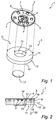
- a light mixing module according to an embodiment of the invention will now be described with reference to Fig. 1 and Fig. 2 .
- Fig. 1 schematically illustrates a luminaire 1 comprising a lighting module 2 and a light mixing module 3.
- the lighting module 2 comprises a first set of light source 4 and a second set of light source 5.
- the first set of light sources 4 are three colored LEDs (one red, one green and one blue) arranged in a centre region 6 of a printed circuit board (PCB) provided in the lighting module
- the second set of light source 5 are six white LEDs distributed across a circumferential region 7 of the PCB enclosing the centre region 6.
- the number of LEDs and the colors of the LEDs may vary due to the illumination desired.
- the LEDs are connected to and powered by a conventional power source (not shown).
- a heat sink (not shown) may be arranged to dissipate heat generated by the LEDs.
- the lighting module preferably has a separation wall 9 arranged between the centre region 6 and the circumferential region 7 such that the colored light can be kept separate from the white light.
- the light mixing module 3 comprises an annular light guiding element 11 having an inner edge 13 defining a cavity 18 with an opening facing the light sources 4,5, a peripheral edge 12, a first intermediate surface 15 extending between the inner and peripheral edges and facing the light sources, and a second intermediate surface 16 extending between the inner and peripheral edges opposite the first intermediate surface 15.
- the annular light guiding element may preferably be transparent and can be made of e.g. glass or plastics, but can be made of any other material suitable for guiding light by total internal reflection.
- the refractive index of the annular light guiding element is here assumed to be 1.5.
- the medium surrounding the annular light guiding element is here assumed to be air, but other materials having a sufficiently low refractive index to guarantee total internal reflection may also be utilized such as a gel or cladding material known from optical fibers.
- the annular light guiding element is circularly symmetric about its longitudinal axis. Furthermore, adjacent surfaces of the annular light guiding element are arranged at a right angle such that the annular light guiding element forms a cylindrical disk with a cylindrical cavity 18.
- the annular light guiding element is arranged such that the opening of the cavity 18 is aligned with the centre region 6 of the lighting module, whereas the first intermediate surface 15 is aligned with the circumferential region 7 of the lighting module.
- the light mixing module further comprises a first reflective surface 17 arranged to close the cavity in an end opposite the opening so as to form a first mixing chamber 18.
- the annular light guiding element may preferably have a depth (i.e. an axial extension) such that the inner edge 13 of the annular light guiding element covers an area at least comparable in size to the area covered by the first reflective surface 17.
- the first reflective surface 17 is here a flat plate of white plastic, but other (semi) specular reflective materials may also be used, such as a MIRO® plate from the company Alanod®.
- light 22 from the colored LEDs 4 enters the cavity 18 in the annular light guiding element via its opening.
- the light is then mixed in the mixing chamber 18 and coupled into the annular light guiding element 11 through its inner edge 13.
- the in-coupled light is then guided in a radial direction through the annular light guiding element 11 by means of total internal reflection and coupled out through the peripheral edge 12.
- light 23 from the white LEDs 5 is in-coupled through the first intermediate surface 15 of the annular light guiding element.
- the in-coupled light is then guided through the light guiding element by means of total internal reflection and coupled out through the second intermediate surface 16.
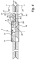
- Figs. 3 and 4 schematically illustrate a dual function lamp or luminaire for lighting up a room, for example in an office, apartment, shop or other public area.
- the luminaire 1 here has a hang-up device 25 that hangs the luminaire to a ceiling (not shown).
- the luminaire includes the light mixing module 3 and the lighting module 2 described above in relation to Figs. 1 and 2 .
- the luminaire further comprises a light guide arrangement 26 arranged to receive light output by the light mixing module 3.
- the light guide arrangement 26 comprises a first (upper) annular light guide 27, placed on top of a second (lower) annular light guide 27', but separated by a suitable medium so that light is allowed to travel inside the respective light guides 27, 27' via total internal reflection (TIR).
- the upper and lower light guides may preferably be transparent and can be made of e.g. glass or plastics, but can be made of any other material suitable for guiding light by total internal reflection.
- the upper light guide 27 is here a circular cylindrical disk with a circular cylindrical cavity (or hole) arranged at the centre of the disk.
- An inner edge 29 of the upper light guide 27 defines the previously described cavity, which is here a through-hole.
- the inner edge 29 of the upper light guide is preferably essentially perpendicular to a (top) surface 30 and a (bottom) surface 31 of the upper light guide 27 to allow light to be coupled into the upper light guide 27 in a radial direction.
- a peripheral edge 32 of the upper light guide 27 preferably has a slanted surface in relation to the top surface 30 and the bottom surface 31 of the upper light guide 27 to couple out light in a desired direction.
- the slanted surface of the peripheral edge 32 of the upper light guide is here configured, in a conventional manner, to couple out the light in an upward direction.
- the design of the lower light guide 27' is consistent with the upper light guide, with the exception that the slanted surface of the peripheral edge 32' of the lower light guide is here configured to couple out the light in a downward direction. Further, the reference numerals used for the lower light guide are the same reference numerals as are used for the upper light guide but with a prime sign (').
- the cavity of the upper light guide is aligned with the cavity of the lower light guide to form a compartment for accommodating the light mixing module 3.
- the light mixing module 3 is arranged in the compartment in such a way that the annular light guiding element 11 is arranged in the same plane as the upper light guide 27, with the lighting module 2 located above the light guide arrangement 26.
- the diameter of the cavity in the upper light guide 27 is selected such that the peripheral edge 12 of the annular light guiding element 11 is separated from the inner edge 29 of the upper annular light guide by an air slit. This prevents the white light 23 from the white LEDs 5 to be coupled into the upper annular light guide 27.
- the air slit may contain a diffuser foil (not shown), e.g. a holographic diffuser foil from the company Luminit.
- the refractive indices of the annular light guiding element 11 and the upper 27 light guide need not be the same, although they may be.
- the luminaire further comprises a second reflective surface 35 arranged such that the inner edge 29' of the second annular light guide, the second intermediate surface 16 of the annular light guiding element and second reflective surface 35 enclose a second mixing chamber 36.
- the first 15 and second 16 reflective surfaces has been formed by arranging a cap beneath the annular light guiding element 11.
- the cap can be made of white plastic and be e.g. injection molded.
- the cap may also be made of (semi) specular reflective material, such as bent MIRO® plates from the company Alanod®.
- the operation of the luminaire where the light mixing module is combined with the light guide arrangement will now be described with reference to Fig. 4 .
- the light emitted by the colored LEDs 4 and the white LEDs 5 are schematically illustrated by exemplary ray traces 22 and 23, respectively.
- colored light 22 is coupled out through the peripheral edge 12 of the annular light guiding element 11 as previously described in relation to Fig. 2 .
- This light is then coupled into the upper annular light guide 27 via its inner edge 29.
- the in-coupled light is then guided inside the upper annular light guide 27 in a radial direction by means of total internal reflection, and coupled out through the peripheral edge 32 in an upward direction to provide colored atmosphere light directed upwards.
- white light 23 is coupled out through the second intermediate surface 16 of the annular light guiding element 11 as previously described in relation to Fig. 2 .
- This light is then mixed in the second mixing chamber 36 and coupled into the lower annular light guide 27' via its inner edge 29'.
- the in-coupled light is then guided inside the lower annular light guide 27' in a radial direction by means of total internal reflection, and coupled out through the peripheral edge 32' of the second annular light guide 27' in a downward direction to provide white task light directed downwards.
- any back-scattered light from the second reflective surface 35 or from the second annular light guide 27' may go back to the white LEDs 5 where it is reflected by the bottom surface of the lighting module (2), but the white light cannot go to the colored LEDs 4 due to TIR.
- the mixing of the light from the colored LEDs 4 in the first mixing chamber 18 promotes a uniform color distribution of the colored light 22.
- any color variations may be further reduced by adding a diffuser at the inner edge 13 of the annular light guiding element 11.
- the peripheral edge 12 of the annular light guiding element 11 and/or the inner edge 29 of the upper light guide 27 may contain groove structures in the axial direction (or lenticular structures in the axial direction) to enhance the mixing effect. It should be noted that grooves along the axial directions do not interfere with the TIR guiding for light travelling along this axial direction.
- the beam width of the light may be broadened by applying diffusers at the peripheral edge 32,32' of the upper 27 and/or lower 27' light guides.
- diffuser foils may be arranged in front of the first intermediate surface 15 and/or the second intermediate surface 16, or radially extending grooves or lenticulars may be provided in the first intermediate surface 15 and/or second 16 intermediate surface.
- these radial grooves extend along the main direction of the light guided by TIR, and therefore does not break up the TIR.
- the groove facets or lenticular facets do help in spreading the light by refraction at the facets.
- the annular light guiding element may have an inner radius of 17.5 mm, an outer radius of 24.3 mm, and a height 5.0 mm.
- the annular light guides may have an inner radius of 25 mm, an outer radius of 150 mm, and a height of 5.0 mm (for each of the two light guides).
- the light mixing module may be combined with other optical elements, such as light guide optics and/or reflector optics.
- the light mixing module may be combined with other optical elements, such as light guide optics and/or reflector optics.
- light that is coupled out through the peripheral edge of the annular light guiding element may enter a first optical system
- light that is coupled out through the second intermediate surface of the annular light guiding element may enter a second optical system, where the first and second systems may create different effects (e.g. up/down, or broad/narrow beams).
- a downward (white) beam can be made with a conventional parabolic reflector, and an upward (colored) light can be made with another parabolic reflector or a (semi) specular reflector that produces a wider beam.
Landscapes
- Physics & Mathematics (AREA)
- General Physics & Mathematics (AREA)
- Optics & Photonics (AREA)
- Non-Portable Lighting Devices Or Systems Thereof (AREA)
- Planar Illumination Modules (AREA)
- Light Guides In General And Applications Therefor (AREA)
Claims (12)
- Module de mélange de lumière (3) apte à recevoir une lumière d'un premier ensemble de sources lumineuses (4) et d'un deuxième ensemble de sources lumineuses (5), ledit module de mélange de lumière comprenant :- un élément de guidage de lumière annulaire (11), ledit élément de guidage de lumière annulaire ayant un bord intérieur (13), un bord périphérique (12), une première surface intermédiaire (15) s'étendant entre lesdits bords intérieur et périphérique et agencée pour faire face au dit deuxième ensemble de sources lumineuses (5), et une deuxième surface intermédiaire (16) s'étendant entre lesdits bords intérieur et périphérique à l'opposé de ladite première surface intermédiaire, dans lequel ledit bord intérieur (13) définit une cavité (18) avec une ouverture agencée pour faire face au dit premier ensemble de sources lumineuses (4), dans lequel ladite ouverture est agencée pour recevoir une lumière provenant dudit premier ensemble de sources lumineuses (4) et ladite première surface intermédiaire (15) est agencée pour recevoir une lumière provenant dudit deuxième ensemble de sources lumineuses (5) ; et- une première surface réfléchissante (17) agencée pour fermer ladite cavité à une extrémité opposée à ladite ouverture de manière à former une première chambre de mélange (18),dans lequel ledit élément de guidage de lumière annulaire (11) et ladite première surface réfléchissante (17) sont agencées de telle manière qu'une lumière entrant par l'intermédiaire de ladite ouverture soit mélangée dans ladite première chambre de mélange (18), couplée dans ledit élément de guidage de lumière annulaire (11) à travers ledit bord intérieur (13), guidée à travers l'élément de guidage de lumière annulaire (11) dans un sens radial au moyen d'une réflexion interne totale et découplée à travers le bord périphérique (12), et la lumière reçue par ladite première surface intermédiaire (15) est guidée à travers ledit élément de guidage de lumière (11) au moyen d'une réflexion interne totale et découplée à travers ladite deuxième surface intermédiaire (16), et
dans lequel une aire du bord intérieur (13) de l'élément de guidage de lumière annulaire est au moins aussi grande qu'une aire de la première surface réfléchissante (17). - Module de mélange de lumière selon la revendication 1, dans lequel le bord intérieur (13) de l'élément de guidage de lumière annulaire est sensiblement perpendiculaire à la première surface intermédiaire (15) de l'élément de guidage de lumière annulaire et à la deuxième surface intermédiaire (16) de l'élément de guidage de lumière annulaire.
- Module de mélange de lumière selon la revendication 1 ou 2, dans lequel ladite première surface intermédiaire (15) est sensiblement perpendiculaire au bord intérieur (13) de l'élément de guidage de lumière annulaire et au bord périphérique (12) de l'élément de guidage de lumière annulaire.
- Module de mélange de lumière selon l'une quelconque des revendications précédentes, dans lequel au moins l'une des surfaces de l'élément de guidage de lumière annulaire est pourvue d'un moyen de diffusion.
- Module de mélange de lumière selon l'une quelconque des revendications précédentes, dans lequel l'élément de guidage de lumière annulaire (11) est circulaire et symétrique par rapport à son axe longitudinal.
- Luminaire (1) comprenant :- un module de mélange de lumière (3) selon l'une quelconque des revendications précédentes ;- un premier ensemble de sources lumineuses (4) agencé pour émettre une lumière qui est reçue par l'ouverture dans l'élément de guidage de lumière annulaire (11) ; et- un deuxième ensemble de sources lumineuses (5) agencé pour émettre une lumière qui est reçue par la première surface intermédiaire (15) de l'élément de guidage de lumière annulaire (11).
- Luminaire selon la revendication 6, dans lequel ledit premier ensemble de sources lumineuses (4) et ledit deuxième ensemble de sources lumineuses (5) sont agencés dans un module d'éclairage (2), dans lequel ledit premier ensemble de sources lumineuses (4) est agencé dans une région centrale (6) dudit module d'éclairage alignée avec l'ouverture de l'élément de guidage de lumière annulaire (11), et ledit deuxième ensemble de sources lumineuses (5) est agencé dans une région circonférentielle (7) dudit module d'éclairage aligné avec la première surface intermédiaire (15) de l'élément de guidage de lumière annulaire.
- Luminaire selon la revendication 6 ou 7, dans lequel le premier ensemble de sources lumineuses (4) est configuré pour émettre une lumière ayant un premier spectre de couleurs, et le deuxième ensemble de sources lumineuses (5) est configuré pour émettre une lumière ayant un deuxième spectre de couleurs différent du premier spectre de couleurs.
- Luminaire selon l'une quelconque des revendications 6 à 8, comprenant en outre un agencement de guide de lumière comprenant :- un premier guide de lumière annulaire (27) agencé dans un premier plan et comportant un bord intérieur (29) définissant une cavité, et un bord périphérique (32) ;- un deuxième guide de lumière annulaire (27') agencé dans un deuxième plan parallèle au dit premier plan et comportant un bord intérieur (29') définissant une cavité, et un bord périphérique (32'),dans lequel la cavité du premier guide de lumière annulaire (27) est alignée avec la cavité du deuxième guide de lumière annulaire (27') pour former un compartiment,
dans lequel le module de mélange de lumière (3) est agencé dans ledit compartiment de telle manière que l'élément de guidage de lumière annulaire (11) soit agencé dans ledit premier plan, tandis que le deuxième guide de lumière annulaire (27') et les sources lumineuses (4, 5) sont agencés sur des côtés opposés dudit premier plan, dans lequel ledit luminaire comprend en outre une deuxième surface réfléchissante (35) agencée de sorte que le bord intérieur (29') du deuxième guide de lumière annulaire, la deuxième surface intermédiaire (16) de l'élément de guidage de lumière annulaire et la deuxième surface réfléchissante (35) renferment une deuxième chambre de mélange (36), dans lequel la deuxième surface réfléchissante (35) est configurée de telle manière qu'une lumière qui est découplée à travers ladite deuxième surface intermédiaire (16) de l'élément de guidage de lumière annulaire soit mélangée dans ladite deuxième chambre de mélange (36) et couplée dans le deuxième guide de lumière annulaire (27') par l'intermédiaire de son bord intérieur (29'),
dans lequel l'agencement de guide de lumière est configuré de sorte qu'une lumière qui est découplée à travers le bord périphérique (12) de l'élément de guidage de lumière annulaire soit couplée dans le premier guide de lumière annulaire (27) par l'intermédiaire de son bord intérieur (29), guidée dans un sens radial au moyen d'une réflexion interne totale, et découplée à travers le bord périphérique (32) du premier guide de lumière annulaire (27), et dans lequel ledit deuxième guide de lumière annulaire est configuré de sorte qu'une lumière qui est couplée dans le deuxième guide de lumière annulaire (27') par l'intermédiaire de son bord intérieur (29') soit guidée dans un sens radial au moyen d'une réflexion interne totale, et découplée à travers le bord périphérique (32') du deuxième guide de lumière annulaire (27'). - Luminaire selon la revendication 9, dans lequel une forme et une taille de la cavité du premier guide de lumière annulaire (27) correspondent sensiblement à une forme et une taille de la périphérie de l'élément de guidage de lumière annulaire (11).
- Luminaire selon la revendication 9 ou 10, dans lequel le premier guide de lumière annulaire (27) est configuré pour découpler une lumière vers un côté du luminaire où les sources lumineuses (4,5) sont agencées.
- Agencement de guide de lumière selon l'une quelconque des revendications 9 à 11, dans lequel le deuxième guide de lumière annulaire (27') est configuré pour découpler une lumière à l'écart d'un côté du luminaire où les sources lumineuses (4, 5) sont agencées.
Priority Applications (1)
| Application Number | Priority Date | Filing Date | Title |
|---|---|---|---|
| EP11713078.1A EP2548055B1 (fr) | 2010-03-18 | 2011-03-10 | Module de mélange de lumière et luminaire le comportant |
Applications Claiming Priority (3)
| Application Number | Priority Date | Filing Date | Title |
|---|---|---|---|
| EP10156909 | 2010-03-18 | ||
| EP11713078.1A EP2548055B1 (fr) | 2010-03-18 | 2011-03-10 | Module de mélange de lumière et luminaire le comportant |
| PCT/IB2011/051009 WO2011114265A1 (fr) | 2010-03-18 | 2011-03-10 | Module de mélange de lumière et luminaire le comportant |
Publications (2)
| Publication Number | Publication Date |
|---|---|
| EP2548055A1 EP2548055A1 (fr) | 2013-01-23 |
| EP2548055B1 true EP2548055B1 (fr) | 2016-09-07 |
Family
ID=44012495
Family Applications (1)
| Application Number | Title | Priority Date | Filing Date |
|---|---|---|---|
| EP11713078.1A Not-in-force EP2548055B1 (fr) | 2010-03-18 | 2011-03-10 | Module de mélange de lumière et luminaire le comportant |
Country Status (6)
| Country | Link |
|---|---|
| US (1) | US9097824B2 (fr) |
| EP (1) | EP2548055B1 (fr) |
| JP (1) | JP5647274B2 (fr) |
| CN (1) | CN102792197B (fr) |
| BR (1) | BR112012023128A8 (fr) |
| WO (1) | WO2011114265A1 (fr) |
Families Citing this family (36)
| Publication number | Priority date | Publication date | Assignee | Title |
|---|---|---|---|---|
| TWM428324U (en) * | 2012-01-13 | 2012-05-01 | Ceramate Technical Co Ltd | Halo-type LED lamp |
| JP2013182730A (ja) * | 2012-02-29 | 2013-09-12 | Sharp Corp | 照明モジュールおよびそれを備えた照明装置 |
| WO2013140337A1 (fr) * | 2012-03-22 | 2013-09-26 | Koninklijke Philips N.V. | Mélange de lumière le long d'un trajet annulaire |
| US8988999B2 (en) * | 2012-05-30 | 2015-03-24 | Intel Corporation | Method, system and apparatus of wireless local area network (WLAN) communication in conjunction with cellular communication |
| WO2014120925A1 (fr) * | 2013-01-30 | 2014-08-07 | Cree, Inc. | Ensemble guide d'ondes optique et moteur lumière le comprenant |
| US9291320B2 (en) * | 2013-01-30 | 2016-03-22 | Cree, Inc. | Consolidated troffer |
| US9366396B2 (en) | 2013-01-30 | 2016-06-14 | Cree, Inc. | Optical waveguide and lamp including same |
| US10422944B2 (en) | 2013-01-30 | 2019-09-24 | Ideal Industries Lighting Llc | Multi-stage optical waveguide for a luminaire |
| US10234616B2 (en) | 2013-01-30 | 2019-03-19 | Cree, Inc. | Simplified low profile module with light guide for pendant, surface mount, wall mount and stand alone luminaires |
| US9625638B2 (en) | 2013-03-15 | 2017-04-18 | Cree, Inc. | Optical waveguide body |
| US10436969B2 (en) | 2013-01-30 | 2019-10-08 | Ideal Industries Lighting Llc | Optical waveguide and luminaire incorporating same |
| US9091417B2 (en) | 2013-03-15 | 2015-07-28 | Cree, Inc. | Lighting apparatus with reflector and outer lens |
| US10209429B2 (en) | 2013-03-15 | 2019-02-19 | Cree, Inc. | Luminaire with selectable luminous intensity pattern |
| US9798072B2 (en) | 2013-03-15 | 2017-10-24 | Cree, Inc. | Optical element and method of forming an optical element |
| US9366799B2 (en) | 2013-03-15 | 2016-06-14 | Cree, Inc. | Optical waveguide bodies and luminaires utilizing same |
| US9222627B2 (en) * | 2013-04-19 | 2015-12-29 | Abl Ip Holding Llc | Annulus shaped luminaire |
| US10036517B2 (en) | 2013-05-16 | 2018-07-31 | 3M Innovative Properties Company | Lightguide as luminaire |
| US9651740B2 (en) | 2014-01-09 | 2017-05-16 | Cree, Inc. | Extraction film for optical waveguide and method of producing same |
| USD725304S1 (en) | 2014-04-21 | 2015-03-24 | Abl Ip Holding Llc | Annulus shaped luminaire |
| USD725305S1 (en) | 2014-04-21 | 2015-03-24 | Abl Ip Holding Llc | Annulus shaped luminaire |
| DE202014103178U1 (de) * | 2014-07-10 | 2015-10-13 | BÄ*RO GmbH & Co. KG | Leuchte, insbesondere Downlight- und/oder Spotlight-Leuchte mit einer Lichtquelle |
| WO2016020323A1 (fr) * | 2014-08-05 | 2016-02-11 | Koninklijke Philips N.V. | Agencement d'éclairage à suppression de couleur d'extrémité |
| DE102014115825A1 (de) * | 2014-10-30 | 2016-05-04 | Itz Innovations- Und Technologiezentrum Gmbh | Leuchtenbaugruppe mit optischem Element |
| JP6600989B2 (ja) * | 2015-05-26 | 2019-11-06 | 株式会社ノーリツ | 照明装置 |
| CN107667245B (zh) * | 2015-05-29 | 2020-03-13 | 飞利浦照明控股有限公司 | 将来自若干led的光进行组合的发光设备 |
| US9689550B2 (en) * | 2015-07-10 | 2017-06-27 | Min Hsiang Corporation | Vehicular lamp device |
| US10416377B2 (en) | 2016-05-06 | 2019-09-17 | Cree, Inc. | Luminaire with controllable light emission |
| US11719882B2 (en) | 2016-05-06 | 2023-08-08 | Ideal Industries Lighting Llc | Waveguide-based light sources with dynamic beam shaping |
| JP6326455B2 (ja) * | 2016-07-27 | 2018-05-16 | 株式会社遠藤照明 | 照明ランプ |
| CN109723981A (zh) * | 2017-10-31 | 2019-05-07 | 霍尼韦尔国际公司 | 一种用于产生环形光晕的装置和方法 |
| CN108826170A (zh) * | 2018-06-26 | 2018-11-16 | 深圳市远润欣电子有限公司 | 局部全般照明的模式、控制方法及台灯 |
| CN209445095U (zh) * | 2018-09-14 | 2019-09-27 | 漳州立达信光电子科技有限公司 | 一种灯具 |
| JP7402407B2 (ja) | 2019-04-18 | 2023-12-21 | 日亜化学工業株式会社 | 発光装置、照明装置及び光学部材 |
| WO2021050668A1 (fr) * | 2019-09-10 | 2021-03-18 | Hubbell Incorporated | Luminaire à auvent |
| WO2022221846A1 (fr) * | 2021-04-16 | 2022-10-20 | Magic Leap, Inc. | Fonction, procédé et processus d'encapsulation de nanostructure dans des composants optiques combinés |
| US11694876B2 (en) | 2021-12-08 | 2023-07-04 | Applied Materials, Inc. | Apparatus and method for delivering a plurality of waveform signals during plasma processing |
Family Cites Families (14)
| Publication number | Priority date | Publication date | Assignee | Title |
|---|---|---|---|---|
| US4450513A (en) | 1982-01-25 | 1984-05-22 | Sterner Lighting Systems Incorporated | Lighting fixture for opposite direction reflection |
| US5055978A (en) | 1989-12-29 | 1991-10-08 | Gte Products Corporation | Uniform light source |
| TW330233B (en) | 1997-01-23 | 1998-04-21 | Philips Eloctronics N V | Luminary |
| JP2000003608A (ja) * | 1998-06-12 | 2000-01-07 | Tsutsunaka Plast Ind Co Ltd | 照明装置 |
| US6256447B1 (en) * | 1998-12-31 | 2001-07-03 | Physical Optics Corporation | Backlight for correcting diagonal line distortion |
| EP1072884A3 (fr) | 1999-07-28 | 2002-01-23 | KELLY, William, M. | Améliorations se rapportant à l'éclairage annulaire |
| US7534013B1 (en) | 2003-01-16 | 2009-05-19 | Simon Jerome H | Illuminating devices using small PT sources including LEDs |
| JP4123189B2 (ja) | 2004-05-19 | 2008-07-23 | ソニー株式会社 | バックライト装置、及び液晶表示装置 |
| JP2010521767A (ja) | 2006-10-16 | 2010-06-24 | コーニンクレッカ フィリップス エレクトロニクス エヌ ヴィ | Ledを備える照明器具 |
| JP2009009926A (ja) * | 2007-03-23 | 2009-01-15 | Toshiba Lighting & Technology Corp | 発光ダイオード照明装置 |
| JP4657248B2 (ja) * | 2007-05-24 | 2011-03-23 | スタンレー電気株式会社 | 照明器具 |
| WO2009105168A2 (fr) | 2008-02-15 | 2009-08-27 | Adaptive Lighting Solutions Llc | Système d’éclairage à base de led fournissant des configurations de distribution de lumière à réglage indépendant |
| CA2726151C (fr) * | 2008-05-30 | 2016-11-22 | Koninklijke Philips Electronics N.V. | Dispositif d'eclairage rond |
| CN201386961Y (zh) * | 2009-03-20 | 2010-01-20 | 海尔集团公司 | 按键开关及其环状发光单元 |
-
2011
- 2011-03-10 US US13/583,650 patent/US9097824B2/en not_active Expired - Fee Related
- 2011-03-10 JP JP2012557639A patent/JP5647274B2/ja not_active Expired - Fee Related
- 2011-03-10 WO PCT/IB2011/051009 patent/WO2011114265A1/fr active Application Filing
- 2011-03-10 CN CN201180014513.2A patent/CN102792197B/zh not_active Expired - Fee Related
- 2011-03-10 EP EP11713078.1A patent/EP2548055B1/fr not_active Not-in-force
- 2011-03-10 BR BR112012023128A patent/BR112012023128A8/pt not_active Application Discontinuation
Also Published As
| Publication number | Publication date |
|---|---|
| JP2013522840A (ja) | 2013-06-13 |
| CN102792197A (zh) | 2012-11-21 |
| CN102792197B (zh) | 2015-07-29 |
| US9097824B2 (en) | 2015-08-04 |
| JP5647274B2 (ja) | 2014-12-24 |
| BR112012023128A2 (pt) | 2017-07-25 |
| US20130003409A1 (en) | 2013-01-03 |
| EP2548055A1 (fr) | 2013-01-23 |
| BR112012023128A8 (pt) | 2017-12-05 |
| WO2011114265A1 (fr) | 2011-09-22 |
Similar Documents
| Publication | Publication Date | Title |
|---|---|---|
| EP2548055B1 (fr) | Module de mélange de lumière et luminaire le comportant | |
| US9366410B2 (en) | Reverse total internal reflection features in linear profile for lighting applications | |
| EP2476943B1 (fr) | Dispositif d'éclairage à DEL plate | |
| KR101203133B1 (ko) | 엘이디 조명 장치 | |
| EP2841846B1 (fr) | Systèmes et procédés d'éclairage | |
| JP5097548B2 (ja) | 照明システム | |
| US8267565B2 (en) | LED illumination device and LED illumination module for generating uniform stripped light source | |
| EP1794640A1 (fr) | Systeme d'eclairage | |
| US20110199780A1 (en) | Illumination device configured to mix light from a first and a second light emitting device | |
| JP2010192439A (ja) | 発光装置及びその導光部材 | |
| JP6446202B2 (ja) | 広角度拡散光学系及びこれを用いた照明装置 | |
| JP5816850B2 (ja) | 照明装置 | |
| JP2015103323A (ja) | 照明装置 | |
| RU2597792C2 (ru) | Светильник, излучающий свет различных цветов | |
| KR20110088130A (ko) | 양면 조명용 led 렌즈와 led 모듈 및 이를 이용한 led 양면 조명장치 | |
| JP6121745B2 (ja) | 面照明発光装置 | |
| KR101837431B1 (ko) | 광품질 개선구조를 갖는 엘이디 조명기구 | |
| KR101876901B1 (ko) | 조명 모듈 | |
| KR20110113702A (ko) | 광원 장치 | |
| JP5350072B2 (ja) | 照明器具 | |
| KR20150108213A (ko) | 조명 장치 | |
| KR101827709B1 (ko) | 조명 모듈 | |
| KR101272690B1 (ko) | 조명 모듈 | |
| KR101272689B1 (ko) | 조명 모듈 | |
| KR20120131998A (ko) | 조명 모듈 |
Legal Events
| Date | Code | Title | Description |
|---|---|---|---|
| PUAI | Public reference made under article 153(3) epc to a published international application that has entered the european phase |
Free format text: ORIGINAL CODE: 0009012 |
|
| 17P | Request for examination filed |
Effective date: 20121018 |
|
| AK | Designated contracting states |
Kind code of ref document: A1 Designated state(s): AL AT BE BG CH CY CZ DE DK EE ES FI FR GB GR HR HU IE IS IT LI LT LU LV MC MK MT NL NO PL PT RO RS SE SI SK SM TR |
|
| DAX | Request for extension of the european patent (deleted) | ||
| RAP1 | Party data changed (applicant data changed or rights of an application transferred) |
Owner name: KONINKLIJKE PHILIPS N.V. |
|
| GRAP | Despatch of communication of intention to grant a patent |
Free format text: ORIGINAL CODE: EPIDOSNIGR1 |
|
| RIC1 | Information provided on ipc code assigned before grant |
Ipc: G02B 6/00 20060101AFI20160321BHEP Ipc: F21V 8/00 20060101ALI20160321BHEP Ipc: F21S 8/06 20060101ALN20160321BHEP |
|
| INTG | Intention to grant announced |
Effective date: 20160408 |
|
| RIC1 | Information provided on ipc code assigned before grant |
Ipc: F21V 8/00 20060101ALI20160330BHEP Ipc: F21S 8/06 20060101ALN20160330BHEP Ipc: G02B 6/00 20060101AFI20160330BHEP |
|
| GRAS | Grant fee paid |
Free format text: ORIGINAL CODE: EPIDOSNIGR3 |
|
| GRAA | (expected) grant |
Free format text: ORIGINAL CODE: 0009210 |
|
| RAP1 | Party data changed (applicant data changed or rights of an application transferred) |
Owner name: PHILIPS LIGHTING HOLDING B.V. |
|
| AK | Designated contracting states |
Kind code of ref document: B1 Designated state(s): AL AT BE BG CH CY CZ DE DK EE ES FI FR GB GR HR HU IE IS IT LI LT LU LV MC MK MT NL NO PL PT RO RS SE SI SK SM TR |
|
| REG | Reference to a national code |
Ref country code: GB Ref legal event code: FG4D |
|
| REG | Reference to a national code |
Ref country code: CH Ref legal event code: EP |
|
| REG | Reference to a national code |
Ref country code: IE Ref legal event code: FG4D |
|
| REG | Reference to a national code |
Ref country code: DE Ref legal event code: R096 Ref document number: 602011030085 Country of ref document: DE |
|
| REG | Reference to a national code |
Ref country code: AT Ref legal event code: REF Ref document number: 827352 Country of ref document: AT Kind code of ref document: T Effective date: 20161015 |
|
| REG | Reference to a national code |
Ref country code: LT Ref legal event code: MG4D |
|
| REG | Reference to a national code |
Ref country code: NL Ref legal event code: MP Effective date: 20160907 |
|
| PG25 | Lapsed in a contracting state [announced via postgrant information from national office to epo] |
Ref country code: LT Free format text: LAPSE BECAUSE OF FAILURE TO SUBMIT A TRANSLATION OF THE DESCRIPTION OR TO PAY THE FEE WITHIN THE PRESCRIBED TIME-LIMIT Effective date: 20160907 Ref country code: FI Free format text: LAPSE BECAUSE OF FAILURE TO SUBMIT A TRANSLATION OF THE DESCRIPTION OR TO PAY THE FEE WITHIN THE PRESCRIBED TIME-LIMIT Effective date: 20160907 Ref country code: RS Free format text: LAPSE BECAUSE OF FAILURE TO SUBMIT A TRANSLATION OF THE DESCRIPTION OR TO PAY THE FEE WITHIN THE PRESCRIBED TIME-LIMIT Effective date: 20160907 Ref country code: HR Free format text: LAPSE BECAUSE OF FAILURE TO SUBMIT A TRANSLATION OF THE DESCRIPTION OR TO PAY THE FEE WITHIN THE PRESCRIBED TIME-LIMIT Effective date: 20160907 Ref country code: NO Free format text: LAPSE BECAUSE OF FAILURE TO SUBMIT A TRANSLATION OF THE DESCRIPTION OR TO PAY THE FEE WITHIN THE PRESCRIBED TIME-LIMIT Effective date: 20161207 |
|
| REG | Reference to a national code |
Ref country code: AT Ref legal event code: MK05 Ref document number: 827352 Country of ref document: AT Kind code of ref document: T Effective date: 20160907 |
|
| PG25 | Lapsed in a contracting state [announced via postgrant information from national office to epo] |
Ref country code: LV Free format text: LAPSE BECAUSE OF FAILURE TO SUBMIT A TRANSLATION OF THE DESCRIPTION OR TO PAY THE FEE WITHIN THE PRESCRIBED TIME-LIMIT Effective date: 20160907 Ref country code: GR Free format text: LAPSE BECAUSE OF FAILURE TO SUBMIT A TRANSLATION OF THE DESCRIPTION OR TO PAY THE FEE WITHIN THE PRESCRIBED TIME-LIMIT Effective date: 20161208 Ref country code: NL Free format text: LAPSE BECAUSE OF FAILURE TO SUBMIT A TRANSLATION OF THE DESCRIPTION OR TO PAY THE FEE WITHIN THE PRESCRIBED TIME-LIMIT Effective date: 20160907 Ref country code: SE Free format text: LAPSE BECAUSE OF FAILURE TO SUBMIT A TRANSLATION OF THE DESCRIPTION OR TO PAY THE FEE WITHIN THE PRESCRIBED TIME-LIMIT Effective date: 20160907 Ref country code: ES Free format text: LAPSE BECAUSE OF FAILURE TO SUBMIT A TRANSLATION OF THE DESCRIPTION OR TO PAY THE FEE WITHIN THE PRESCRIBED TIME-LIMIT Effective date: 20160907 |
|
| REG | Reference to a national code |
Ref country code: FR Ref legal event code: PLFP Year of fee payment: 7 |
|
| PG25 | Lapsed in a contracting state [announced via postgrant information from national office to epo] |
Ref country code: RO Free format text: LAPSE BECAUSE OF FAILURE TO SUBMIT A TRANSLATION OF THE DESCRIPTION OR TO PAY THE FEE WITHIN THE PRESCRIBED TIME-LIMIT Effective date: 20160907 Ref country code: EE Free format text: LAPSE BECAUSE OF FAILURE TO SUBMIT A TRANSLATION OF THE DESCRIPTION OR TO PAY THE FEE WITHIN THE PRESCRIBED TIME-LIMIT Effective date: 20160907 |
|
| PG25 | Lapsed in a contracting state [announced via postgrant information from national office to epo] |
Ref country code: CZ Free format text: LAPSE BECAUSE OF FAILURE TO SUBMIT A TRANSLATION OF THE DESCRIPTION OR TO PAY THE FEE WITHIN THE PRESCRIBED TIME-LIMIT Effective date: 20160907 Ref country code: BG Free format text: LAPSE BECAUSE OF FAILURE TO SUBMIT A TRANSLATION OF THE DESCRIPTION OR TO PAY THE FEE WITHIN THE PRESCRIBED TIME-LIMIT Effective date: 20161207 Ref country code: SM Free format text: LAPSE BECAUSE OF FAILURE TO SUBMIT A TRANSLATION OF THE DESCRIPTION OR TO PAY THE FEE WITHIN THE PRESCRIBED TIME-LIMIT Effective date: 20160907 Ref country code: AT Free format text: LAPSE BECAUSE OF FAILURE TO SUBMIT A TRANSLATION OF THE DESCRIPTION OR TO PAY THE FEE WITHIN THE PRESCRIBED TIME-LIMIT Effective date: 20160907 Ref country code: PT Free format text: LAPSE BECAUSE OF FAILURE TO SUBMIT A TRANSLATION OF THE DESCRIPTION OR TO PAY THE FEE WITHIN THE PRESCRIBED TIME-LIMIT Effective date: 20170109 Ref country code: BE Free format text: LAPSE BECAUSE OF FAILURE TO SUBMIT A TRANSLATION OF THE DESCRIPTION OR TO PAY THE FEE WITHIN THE PRESCRIBED TIME-LIMIT Effective date: 20160907 Ref country code: SK Free format text: LAPSE BECAUSE OF FAILURE TO SUBMIT A TRANSLATION OF THE DESCRIPTION OR TO PAY THE FEE WITHIN THE PRESCRIBED TIME-LIMIT Effective date: 20160907 Ref country code: PL Free format text: LAPSE BECAUSE OF FAILURE TO SUBMIT A TRANSLATION OF THE DESCRIPTION OR TO PAY THE FEE WITHIN THE PRESCRIBED TIME-LIMIT Effective date: 20160907 Ref country code: IS Free format text: LAPSE BECAUSE OF FAILURE TO SUBMIT A TRANSLATION OF THE DESCRIPTION OR TO PAY THE FEE WITHIN THE PRESCRIBED TIME-LIMIT Effective date: 20170107 |
|
| REG | Reference to a national code |
Ref country code: DE Ref legal event code: R097 Ref document number: 602011030085 Country of ref document: DE |
|
| PG25 | Lapsed in a contracting state [announced via postgrant information from national office to epo] |
Ref country code: IT Free format text: LAPSE BECAUSE OF FAILURE TO SUBMIT A TRANSLATION OF THE DESCRIPTION OR TO PAY THE FEE WITHIN THE PRESCRIBED TIME-LIMIT Effective date: 20160907 |
|
| PLBE | No opposition filed within time limit |
Free format text: ORIGINAL CODE: 0009261 |
|
| STAA | Information on the status of an ep patent application or granted ep patent |
Free format text: STATUS: NO OPPOSITION FILED WITHIN TIME LIMIT |
|
| RIN2 | Information on inventor provided after grant (corrected) |
Inventor name: DEKKER, TIM Inventor name: VISSENBERG, MICHEL CORNELIS JOSEPHUS MARIE |
|
| PG25 | Lapsed in a contracting state [announced via postgrant information from national office to epo] |
Ref country code: DK Free format text: LAPSE BECAUSE OF FAILURE TO SUBMIT A TRANSLATION OF THE DESCRIPTION OR TO PAY THE FEE WITHIN THE PRESCRIBED TIME-LIMIT Effective date: 20160907 |
|
| 26N | No opposition filed |
Effective date: 20170608 |
|
| PG25 | Lapsed in a contracting state [announced via postgrant information from national office to epo] |
Ref country code: SI Free format text: LAPSE BECAUSE OF FAILURE TO SUBMIT A TRANSLATION OF THE DESCRIPTION OR TO PAY THE FEE WITHIN THE PRESCRIBED TIME-LIMIT Effective date: 20160907 |
|
| REG | Reference to a national code |
Ref country code: CH Ref legal event code: PL |
|
| PG25 | Lapsed in a contracting state [announced via postgrant information from national office to epo] |
Ref country code: MC Free format text: LAPSE BECAUSE OF FAILURE TO SUBMIT A TRANSLATION OF THE DESCRIPTION OR TO PAY THE FEE WITHIN THE PRESCRIBED TIME-LIMIT Effective date: 20160907 |
|
| REG | Reference to a national code |
Ref country code: IE Ref legal event code: MM4A |
|
| PG25 | Lapsed in a contracting state [announced via postgrant information from national office to epo] |
Ref country code: LU Free format text: LAPSE BECAUSE OF NON-PAYMENT OF DUE FEES Effective date: 20170310 |
|
| PG25 | Lapsed in a contracting state [announced via postgrant information from national office to epo] |
Ref country code: CH Free format text: LAPSE BECAUSE OF NON-PAYMENT OF DUE FEES Effective date: 20170331 Ref country code: LI Free format text: LAPSE BECAUSE OF NON-PAYMENT OF DUE FEES Effective date: 20170331 Ref country code: IE Free format text: LAPSE BECAUSE OF NON-PAYMENT OF DUE FEES Effective date: 20170310 |
|
| REG | Reference to a national code |
Ref country code: FR Ref legal event code: PLFP Year of fee payment: 8 |
|
| PG25 | Lapsed in a contracting state [announced via postgrant information from national office to epo] |
Ref country code: MT Free format text: LAPSE BECAUSE OF NON-PAYMENT OF DUE FEES Effective date: 20170310 |
|
| PG25 | Lapsed in a contracting state [announced via postgrant information from national office to epo] |
Ref country code: AL Free format text: LAPSE BECAUSE OF FAILURE TO SUBMIT A TRANSLATION OF THE DESCRIPTION OR TO PAY THE FEE WITHIN THE PRESCRIBED TIME-LIMIT Effective date: 20160907 |
|
| PG25 | Lapsed in a contracting state [announced via postgrant information from national office to epo] |
Ref country code: HU Free format text: LAPSE BECAUSE OF FAILURE TO SUBMIT A TRANSLATION OF THE DESCRIPTION OR TO PAY THE FEE WITHIN THE PRESCRIBED TIME-LIMIT; INVALID AB INITIO Effective date: 20110310 |
|
| PG25 | Lapsed in a contracting state [announced via postgrant information from national office to epo] |
Ref country code: CY Free format text: LAPSE BECAUSE OF NON-PAYMENT OF DUE FEES Effective date: 20160907 |
|
| PG25 | Lapsed in a contracting state [announced via postgrant information from national office to epo] |
Ref country code: MK Free format text: LAPSE BECAUSE OF FAILURE TO SUBMIT A TRANSLATION OF THE DESCRIPTION OR TO PAY THE FEE WITHIN THE PRESCRIBED TIME-LIMIT Effective date: 20160907 |
|
| PG25 | Lapsed in a contracting state [announced via postgrant information from national office to epo] |
Ref country code: TR Free format text: LAPSE BECAUSE OF FAILURE TO SUBMIT A TRANSLATION OF THE DESCRIPTION OR TO PAY THE FEE WITHIN THE PRESCRIBED TIME-LIMIT Effective date: 20160907 |
|
| REG | Reference to a national code |
Ref country code: DE Ref legal event code: R082 Ref document number: 602011030085 Country of ref document: DE Representative=s name: MEISSNER BOLTE PATENTANWAELTE RECHTSANWAELTE P, DE Ref country code: DE Ref legal event code: R081 Ref document number: 602011030085 Country of ref document: DE Owner name: SIGNIFY HOLDING B.V., NL Free format text: FORMER OWNER: PHILIPS LIGHTING HOLDING B.V., EINDHOVEN, NL |
|
| REG | Reference to a national code |
Ref country code: FR Ref legal event code: PLFP Year of fee payment: 12 |
|
| PGFP | Annual fee paid to national office [announced via postgrant information from national office to epo] |
Ref country code: GB Payment date: 20220322 Year of fee payment: 12 |
|
| PGFP | Annual fee paid to national office [announced via postgrant information from national office to epo] |
Ref country code: FR Payment date: 20220325 Year of fee payment: 12 |
|
| PGFP | Annual fee paid to national office [announced via postgrant information from national office to epo] |
Ref country code: DE Payment date: 20220527 Year of fee payment: 12 |
|
| REG | Reference to a national code |
Ref country code: DE Ref legal event code: R119 Ref document number: 602011030085 Country of ref document: DE |
|
| GBPC | Gb: european patent ceased through non-payment of renewal fee |
Effective date: 20230310 |
|
| PG25 | Lapsed in a contracting state [announced via postgrant information from national office to epo] |
Ref country code: GB Free format text: LAPSE BECAUSE OF NON-PAYMENT OF DUE FEES Effective date: 20230310 |
|
| PG25 | Lapsed in a contracting state [announced via postgrant information from national office to epo] |
Ref country code: GB Free format text: LAPSE BECAUSE OF NON-PAYMENT OF DUE FEES Effective date: 20230310 Ref country code: FR Free format text: LAPSE BECAUSE OF NON-PAYMENT OF DUE FEES Effective date: 20230331 Ref country code: DE Free format text: LAPSE BECAUSE OF NON-PAYMENT OF DUE FEES Effective date: 20231003 |