EP2547434B1 - Catalytic fixed bed reactor and method for producing ethylene oxide by partial oxidation of ethylene - Google Patents
Catalytic fixed bed reactor and method for producing ethylene oxide by partial oxidation of ethylene Download PDFInfo
- Publication number
- EP2547434B1 EP2547434B1 EP11712373.7A EP11712373A EP2547434B1 EP 2547434 B1 EP2547434 B1 EP 2547434B1 EP 11712373 A EP11712373 A EP 11712373A EP 2547434 B1 EP2547434 B1 EP 2547434B1
- Authority
- EP
- European Patent Office
- Prior art keywords
- catalyst
- coolant
- catalyst bed
- reactor
- flow
- Prior art date
- Legal status (The legal status is an assumption and is not a legal conclusion. Google has not performed a legal analysis and makes no representation as to the accuracy of the status listed.)
- Active
Links
Images





Classifications
-
- B—PERFORMING OPERATIONS; TRANSPORTING
- B01—PHYSICAL OR CHEMICAL PROCESSES OR APPARATUS IN GENERAL
- B01J—CHEMICAL OR PHYSICAL PROCESSES, e.g. CATALYSIS OR COLLOID CHEMISTRY; THEIR RELEVANT APPARATUS
- B01J19/00—Chemical, physical or physico-chemical processes in general; Their relevant apparatus
- B01J19/24—Stationary reactors without moving elements inside
-
- B—PERFORMING OPERATIONS; TRANSPORTING
- B01—PHYSICAL OR CHEMICAL PROCESSES OR APPARATUS IN GENERAL
- B01J—CHEMICAL OR PHYSICAL PROCESSES, e.g. CATALYSIS OR COLLOID CHEMISTRY; THEIR RELEVANT APPARATUS
- B01J8/00—Chemical or physical processes in general, conducted in the presence of fluids and solid particles; Apparatus for such processes
- B01J8/02—Chemical or physical processes in general, conducted in the presence of fluids and solid particles; Apparatus for such processes with stationary particles, e.g. in fixed beds
- B01J8/0242—Chemical or physical processes in general, conducted in the presence of fluids and solid particles; Apparatus for such processes with stationary particles, e.g. in fixed beds the fluid flow within the bed being predominantly vertical
-
- B—PERFORMING OPERATIONS; TRANSPORTING
- B01—PHYSICAL OR CHEMICAL PROCESSES OR APPARATUS IN GENERAL
- B01J—CHEMICAL OR PHYSICAL PROCESSES, e.g. CATALYSIS OR COLLOID CHEMISTRY; THEIR RELEVANT APPARATUS
- B01J8/00—Chemical or physical processes in general, conducted in the presence of fluids and solid particles; Apparatus for such processes
- B01J8/02—Chemical or physical processes in general, conducted in the presence of fluids and solid particles; Apparatus for such processes with stationary particles, e.g. in fixed beds
- B01J8/0242—Chemical or physical processes in general, conducted in the presence of fluids and solid particles; Apparatus for such processes with stationary particles, e.g. in fixed beds the fluid flow within the bed being predominantly vertical
- B01J8/0264—Chemical or physical processes in general, conducted in the presence of fluids and solid particles; Apparatus for such processes with stationary particles, e.g. in fixed beds the fluid flow within the bed being predominantly vertical in a conically shaped bed
-
- B—PERFORMING OPERATIONS; TRANSPORTING
- B01—PHYSICAL OR CHEMICAL PROCESSES OR APPARATUS IN GENERAL
- B01J—CHEMICAL OR PHYSICAL PROCESSES, e.g. CATALYSIS OR COLLOID CHEMISTRY; THEIR RELEVANT APPARATUS
- B01J8/00—Chemical or physical processes in general, conducted in the presence of fluids and solid particles; Apparatus for such processes
- B01J8/02—Chemical or physical processes in general, conducted in the presence of fluids and solid particles; Apparatus for such processes with stationary particles, e.g. in fixed beds
- B01J8/0285—Heating or cooling the reactor
-
- C—CHEMISTRY; METALLURGY
- C07—ORGANIC CHEMISTRY
- C07D—HETEROCYCLIC COMPOUNDS
- C07D301/00—Preparation of oxiranes
- C07D301/02—Synthesis of the oxirane ring
- C07D301/03—Synthesis of the oxirane ring by oxidation of unsaturated compounds, or of mixtures of unsaturated and saturated compounds
- C07D301/04—Synthesis of the oxirane ring by oxidation of unsaturated compounds, or of mixtures of unsaturated and saturated compounds with air or molecular oxygen
- C07D301/08—Synthesis of the oxirane ring by oxidation of unsaturated compounds, or of mixtures of unsaturated and saturated compounds with air or molecular oxygen in the gaseous phase
-
- C—CHEMISTRY; METALLURGY
- C07—ORGANIC CHEMISTRY
- C07D—HETEROCYCLIC COMPOUNDS
- C07D301/00—Preparation of oxiranes
- C07D301/02—Synthesis of the oxirane ring
- C07D301/03—Synthesis of the oxirane ring by oxidation of unsaturated compounds, or of mixtures of unsaturated and saturated compounds
- C07D301/04—Synthesis of the oxirane ring by oxidation of unsaturated compounds, or of mixtures of unsaturated and saturated compounds with air or molecular oxygen
- C07D301/08—Synthesis of the oxirane ring by oxidation of unsaturated compounds, or of mixtures of unsaturated and saturated compounds with air or molecular oxygen in the gaseous phase
- C07D301/10—Synthesis of the oxirane ring by oxidation of unsaturated compounds, or of mixtures of unsaturated and saturated compounds with air or molecular oxygen in the gaseous phase with catalysts containing silver or gold
-
- B—PERFORMING OPERATIONS; TRANSPORTING
- B01—PHYSICAL OR CHEMICAL PROCESSES OR APPARATUS IN GENERAL
- B01J—CHEMICAL OR PHYSICAL PROCESSES, e.g. CATALYSIS OR COLLOID CHEMISTRY; THEIR RELEVANT APPARATUS
- B01J2208/00—Processes carried out in the presence of solid particles; Reactors therefor
- B01J2208/00008—Controlling the process
- B01J2208/00017—Controlling the temperature
- B01J2208/00106—Controlling the temperature by indirect heat exchange
- B01J2208/00115—Controlling the temperature by indirect heat exchange with heat exchange elements inside the bed of solid particles
-
- B—PERFORMING OPERATIONS; TRANSPORTING
- B01—PHYSICAL OR CHEMICAL PROCESSES OR APPARATUS IN GENERAL
- B01J—CHEMICAL OR PHYSICAL PROCESSES, e.g. CATALYSIS OR COLLOID CHEMISTRY; THEIR RELEVANT APPARATUS
- B01J2208/00—Processes carried out in the presence of solid particles; Reactors therefor
- B01J2208/00008—Controlling the process
- B01J2208/00017—Controlling the temperature
- B01J2208/00106—Controlling the temperature by indirect heat exchange
- B01J2208/00115—Controlling the temperature by indirect heat exchange with heat exchange elements inside the bed of solid particles
- B01J2208/00141—Coils
-
- B—PERFORMING OPERATIONS; TRANSPORTING
- B01—PHYSICAL OR CHEMICAL PROCESSES OR APPARATUS IN GENERAL
- B01J—CHEMICAL OR PHYSICAL PROCESSES, e.g. CATALYSIS OR COLLOID CHEMISTRY; THEIR RELEVANT APPARATUS
- B01J2208/00—Processes carried out in the presence of solid particles; Reactors therefor
- B01J2208/00008—Controlling the process
- B01J2208/00548—Flow
- B01J2208/00557—Flow controlling the residence time inside the reactor vessel
-
- B—PERFORMING OPERATIONS; TRANSPORTING
- B01—PHYSICAL OR CHEMICAL PROCESSES OR APPARATUS IN GENERAL
- B01J—CHEMICAL OR PHYSICAL PROCESSES, e.g. CATALYSIS OR COLLOID CHEMISTRY; THEIR RELEVANT APPARATUS
- B01J2208/00—Processes carried out in the presence of solid particles; Reactors therefor
- B01J2208/00796—Details of the reactor or of the particulate material
- B01J2208/00893—Feeding means for the reactants
-
- B—PERFORMING OPERATIONS; TRANSPORTING
- B01—PHYSICAL OR CHEMICAL PROCESSES OR APPARATUS IN GENERAL
- B01J—CHEMICAL OR PHYSICAL PROCESSES, e.g. CATALYSIS OR COLLOID CHEMISTRY; THEIR RELEVANT APPARATUS
- B01J2208/00—Processes carried out in the presence of solid particles; Reactors therefor
- B01J2208/02—Processes carried out in the presence of solid particles; Reactors therefor with stationary particles
Definitions
- reactors for producing ethylene oxide (EO) by partial oxidation of ethylene typically make use of a single conventional fixed-bed shell-tube exchanger (FB) where the catalytic reaction occurs inside the tubes.
- FB fixed-bed shell-tube exchanger
- the fabrication of this type of reactor has reached engineering and transportation limitations due to weight and size factors. It is typical in a conventional design to have 8,000-14,000 tubes with up to 2" (50.8 mm) internal diameter tubes (Dt) arranged in the shell diameter (Ds) with a Ds of 6-9 meters (M) and tube sheets approaching 1.0 ft to 2.0 ft (0.3 to 0.61 m) in thickness.
- a reactor with an even larger Dt and Ds can theoretically be used to provide a more economically advantageous process given the continually advancing catalyst formulations that are improving average selectivity of 80% to 95% during such a reactor's life time.
- the disclosure relates to a reaction vessel for production of alkylene oxide(s) from partial oxidation of hydrocarbon using a high efficiency heterogeneous catalyst in a fixed bed enclosed within a reaction vessel shell.
- the reaction vessel comprises a shell having an inflow and an outflow; said shell with a length and width to define a reactor vessel interior volume; a catalyst bed shape defined by said reactor volume, wherein the catalyst bed is such that the cross sectional area at any points A1 and A2, between the in flow and the out flow, separated by a length L1 along the catalyst bed are such that (A2-A1)/L1 is from 0.8 to 1.3m ; said catalyst bed including a catalyst having a selectivity greater than 80%, said catalyst bed defining a process side and having a length less than said shell length and a volume less than said shell volume; a fixed bed outlet zone configured with an average residence time less than or equal to 4 seconds of a gaseous flow from said catalyst bed to a heat exchanger to quench the reactions; said catalyst bed forming a
- the disclosure relates to at least one method for producing ethylene oxide from partial oxidation of ethylene using a high efficiency ethylene oxide catalyst in a fixed bed enclosed within a shell of a reaction vessel.
- the method may comprise a method for producing gaseous ethylene oxide product from partial oxidationof hydrocarbon using a heterogeneous catalyst in a fixed bed enclosed within a reaction vessel shell, comprising introducing a sufficient amount of gaseous ethylene, oxygen, ballast gas, and catalyst promoter into a reaction vessel having an inflow and an outflow, said vessel having a shell with a length and a width to define a reactor vessel volume; said reactor vessel volume defining a catalyst bed shape; wherein the catalyst bed is such that the cross sectional area at any points A1 and A2, between the in flow and the out flow, separated by a length L1 along the catalyst bed are such that (A2-A1)/L1 is from 0.8 to 1.3m said catalyst bed defining a process side and having a selectivity greater than 80%, said catalyst
- GB472629A discloses the oxidation of olefines to olefine oxides in the gaseous phase according by passage over catalytic material in thin layer form contained in tubes of heat conducting material immersed in a liquid maintained at constant temperature.
- the temperature control is improved by providing within the tube or tubes a continuous or stepped gradation of one or more of surface area or thickness or activity of catalyst, velocity of gas flow, turbulence and cross-sectional area of the gas passage
- DE2204539 discloses reactors, of which the shape of the interior is modified by use of a ceramic, refractory lining, and/or by the insertion of a compact, inactive conically-shaped profile with a plane or pyramid-shaped base, the arrangement of shape and form of the lining being correlated so that the cross section of the reaction zone varies in a single direction only, either upwards or downwards, for the purpose of providing the optimum correlation of temperature and time of contact.
- US2002161243 discloses a process for the preparation of maleic anhydride by heterogeneously catalyzed gas-phase oxidation in a reactor with feed for the reaction mixture at one end of the reactor and discharge of the product mixture at the opposite end of the reactor, and with devices for dissipating the heat of reaction which are arranged in the reactor interior and through which a heat-exchange medium flows and which are designed as heat-exchanger plates.
- Figure 1 is a schematic representation of a reaction vessel 10 having a shell enclosure 12 of a length and width that defines an internal space 14.
- the shell is a wall with an inner surface 16 and an outer surface 18, separated by an insulation layer 20. While the shell is shown schematically, those skilled in the art understand that it could be constructed in any shape desired.
- the shell is constructed of materials having sufficient strength to contain the internal pressures that arise as the operation of the reaction vessel as is well known in the art.
- the reaction vessel is further equipped with an in flow 22 for ingress of hydrocarbon or other gaseous raw materials, such as, for example ethylene, oxygen, ballast gases, and gaseous catalyst promoters, into the feed distribution device 24 and an out flow 26 for effluent gaseous products.
- hydrocarbon or other gaseous raw materials such as, for example ethylene, oxygen, ballast gases, and gaseous catalyst promoters
- ballast gases are understood to be, but are not limited to, CO 2 , CH 4 , inert gasses such as N 2 , Helium, Argon, or any other noble gas.
- catalyst promoters may be, but are not limited to, ammonia (NH3), especially for high selectivity catalysts, chlorides, vinyl chloride, ethyl chloride, ethane, and any other suitable gaseous promoter.
- the in flow and the out flow of the shell are configured to produce an exit gas velocity of from about 5 ft/s, to about 25 ft/s (1.5 to 7.5 m/s), upon exiting the fixed bed reaction zone within the reactor vessel before entering an outlet pipe 31.
- the gaseous in flow and out flow have an absolute difference ratio of inlet and outlet flow area over the catalyst bed length from about 0.8 meters to about 1.3 meters and more preferably from about 0.9 to about 1.2 meters.
- the shell has an interior pressure during gaseous raw material ingress and gaseous effluent product egress of less than about 350 psig (2.5MPa).
- a catalyst bed 28 carried within the shell made of a high or low selectivity catalyst for the oxidation of the gaseous raw material, such as, for example ethylene, to ethylene oxide in a manner to be hereinafter described.
- the catalyst bed is also known as the process side of the reactor and has a length and a width and defines a volume that is less than the volume of the shell.
- the catalyst bed has a length L1 such that between the out flow area and the in flow area over the catalyst bed length in between the out flow and the in flow, has an absolute ratio difference as expressed in (A2-A1)/L1 that is less than or equal to about 1.3M.
- Proximal to the out flow is fixed bed outlet zone 30 to minimize residence time of the effluent product material after exiting the catalytic bed.
- the fixed bed outlet zone is configured with an average residence time of less than or about 4 seconds for the gaseous product flow from the outlet of the catalyst bed to a heat exchanger to quench any undesired side reaction further converting alkylene oxide product to other unwanted byproducts such as CO 2 , H 2 O, carbon, and CH 4 .
- the catalyst may be selected from the group of catalysts with a lifetime selectivity higher than about 80%. Suitable catalysts may include, without limitation, a low selectivity catalyst such as SureCat® or a high selectivity catalyst such as Meteor®, both available from The Dow Chemical Company.
- a low selectivity catalyst such as SureCat®
- a high selectivity catalyst such as Meteor®, both available from The Dow Chemical Company.
- the bed is a low selectivity catalyst, the bed has a density in a range from about 960 kg/m 3 to about 774 kg/m 3
- a high selectivity catalyst is used as the catalyst bed, the bed has a density in a range from about 837 kg/m 3 to about 715 kg/m 3 .
- the catalyst may be pills having a diffusion length from about 0.02 inches to about 0.07 inches (0.508 mm to 1.778 mm), and more preferably, from about 0.025 inches to about 0.06 inches (0.635 mm to 1.524 mm).
- the pill diffusion length can be determined by the ratio of the volume of a catalyst pellet to its exterior surface available for reactant penetration and diffusion. A more detailed definition and example can be found on page 476 of " Chemical Reaction Engineering", second edition, Wiley & Sons, 1972 . If a low selectivity catalyst is used, the preferred catalyst bed should have a length great than or equal to about 9.5 M, and if a high selectivity catalyst is used as the catalyst bed, the preferred bed should have a length greater than or equal to about 8.5 M.
- the reactor vessel is further equipped with a coolant fluid enclosure heat exchanger 32 having an inlet 34 and an outlet 36 for the circulation of heat transfer fluid through the vessel in a manner that may be parallel or cross wise to the direction of gaseous raw material flow through the catalyst bed.
- the coolant enclosure is generally designated as the coolant side of the reactor, and has an outer surface 38 in contact with the catalyst bed, and an inner surface 40, in contact with the heat transfer fluid.
- the coolant enclosure defines a coolant surface area with a heat transfer fluid flow cross sectional area ratio to the coolant surface area much less than 1.
- the coolant enclosure surface area ratio to catalyst bed volume is preferably less than or equal to about 187 1/M.
- the heat transfer fluid may be boiling water in the coolant enclosure at a pressure of up to about 750 psig (5.27 MPa) to maintain temperature in the catalyst bed at a temperature up to about 270°C.
- the pressure in the coolant side is preferably greater than the pressure on the process side of the reaction vessel.
- the catalyst bed has an oxidation catalyst of a selectivity greater than about 80%, and, as previously stated, the flow of gaseous raw material through the catalyst bed may be parallel or cross to the direction of flow of heat transfer fluids in the heat transfer fluid enclosure. Accordingly, the coolant enclosure flow may be parallel, helical, perpendicular or in any other direction to the direction of flow of the gaseous raw material through the catalyst bed.
- the invention is illustrated in particular in Example 4, with various preferred aspects and features illustrated in Examples 1-3 and 5-8.
- XCSA cross flow catalyst-in-shell reactor
- GHSV Gas Hourly Space Velocity
- ⁇ catalyst volume ratio
- SI calculated sensitivity index
- ⁇ P pressure drop
- STR conventional reactor with catalyst bed inside the tube.
- FIG. 2A is an evaluation of a catalyst-in-shell side reactor design with cross flow (XCSA) for low selectivity catalyst with GHSV of 5631 1/hr.
- XCSA catalyst-in-shell side reactor design with cross flow
- the STR case tube ID is such that the heat transfer area over catalyst volume ratio ( ⁇ ) is 86 1/M.
- ⁇ heat transfer area over catalyst volume ratio
- the XCSA design will show improved stability as shown by the larger calculated sensitivity index (SI), lower weight and lower pressure drop ( ⁇ P) and even lower ⁇ with XCSA reactor bed length between 6.7 and 11.7 M as shown in Figure 2A . It is also apparent that the ⁇ P decreases with a lower bed length while in contrast the reactor weight increases with lower bed length.
- FIG. 2B is an evaluation of catalyst-in-shell side reactor design with cross flow (XCSA) for low selectivity catalyst with GHSV of 7525 1/hr.
- XCSA catalyst-in-shell side reactor design with cross flow
- Table 2 also shows that significant improvement in the ⁇ (and thus reactor weight) may be obtainable at various coolant tube OD (e.g. XCSA 2, 5 and 8) while still providing lower ⁇ Ps than that of STR cases.
- ⁇ P can be much lower than that in STR cases for various coolant tubes OD while still maintaining lower weight ratio (e.g. case XCSA 3, 6, and 9).
- Table 2 Evaluation of catalyst-in-shell side reactor design with cross flow (XCSA) and comparison with conventional fixed bed reactor for lower selectivity catalyst for GHSV of 5631 1/hr. Coolant tubes having OD of 0.75 in (19.1 mm), 1 in (25.4 mm) and 1.25 in (31.8 mm) are used.
- FIG. 2C is a plot showing the prediction of heat transfer area to catalyst volume ratio ⁇ as a function of reactor bed length for XCSA reactor design with various coolant tube diameters and various coolant temperatures yielding different work rates (work rate is indicated in legend in lbs/ft 3 -hr) for low selectivity catalyst.
- Figure 2C also shows the prediction that the ⁇ of XCSA design concept is always lower than or equal to ⁇ STR of 86 1/M when the catalyst bed length is equal to or larger than 6.5 M. In addition, this is also predicted to be true for all coolant tubes OD of 0.6" to 1.5" (15 mm to 38 mm) and at various coolant temperatures. Note that Figure 2C also demonstrates that the XCSA design can provide lower weight, higher stability, and lower ⁇ P with bed length up to about an 11 M bed than that of the STR design.
- FIG. 2D is plot showing prediction of heat transfer area to catalyst volume ratio ⁇ as a function of reactor bed length for XCSA reactor design at different GHSV values for a low selectivity catalyst.
- This also illustrates that the XCSA design of Figure 2E is expected to show better expected stability, requires lower expected reactor weight and ⁇ P at the same operating conditions as STR with tube OD of 0.84" (21.3 mm) in the range of 6.5M to 11M bed length.
- work rate is indicated in legend in lbs/ft 3 -hr
- 1 lb/ft 3 -hr 16 Kg/m 3 -hr.
- the expected ⁇ P, 1/SI and weight ratio with STR case are also plotted as a function of bed length.
- Figure 2F also depicts the expected XCSA advantageous bed length range of 5.8 M to 12.0 M.
- work rate is indicated in legend in lbs/ft 3 -hr
- 1 lb/ft 3 -hr 16 Kg/m 3 -hr.
- the expected ⁇ P, 1/SI and weight ratio with STR case are also plotted as a function of bed length.
- Figure 2G also depicts the expected XCSA advantageous bed length range of 7.5 M to 11.5 M.
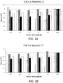
- FIG. 3A is a predicted evaluation of a catalyst-in-shell side reactor design with cross flow (XCSA) for a high selectivity catalyst with a GHSV of 6652 1/hr.
- the STR case is using a 2" (50.8 mm) tube OD (1.83" (46.5 mm) ID) for a conventional shell and tube reactor with catalyst-in-tube design.
- the catalyst on the shell side with cross flow (XCSA) design with 0.75" (109 mm) coolant tube with GHSV 6652 1/hr is expected to show advantages over the conventional shell and tube reactor with catalyst-in-tube (STR) design with 2" tube OD (1.83" (46.5 mm) ID).
- Figure 3A depicts that the expected XCSA design requires lower ⁇ than the STR design and also shows predicted improved stability, lower reactor weight and lower pressure drop ( ⁇ P) with reactor bed length between 6M and 9M.
- FIG. 3B is an evaluation of a predicted catalyst-in-shell side reactor design with cross flow (XCSA) for a high selectivity (HS) catalyst (Meteor) with a GHSV of 8500 1/hr.
- XCSA catalyst-in-shell side reactor design with cross flow
- HS high selectivity
- Metal Metal
- the STR case is with a 2" (50.8 mm) tube OD (1.83" (46.5 mm) ID) conventional shell and tube reactor with catalyst-in-tube design.
- Table 3 shows the detailed calculations expected results for HS catalyst and also shows that similar improvement can be expected to be achieved in an XCSA design over an STR design by using different coolant tube OD's while keeping catalyst volume and other operating conditions (coolant Temperature, GHSV, production rate, inlet pressure, inlet gas temperature) similar to the STR case.
- Table 3 also shows that significant improvement in the ⁇ (thus reactor weight) is expected to be obtained at various coolant tube OD's (e.g. XCSA 2, 5 and 8) while still providing similar or lower ⁇ P than that of the STR case. Note that ⁇ P is expected to be much lower than that in STR case for various coolant tube OD while still maintaining lower weight ratio (e.g. case XCSA 1, 2, 6 and 7).
- Table 3 Catalyst-in-shell side reactor designs with cross flow (XCSA) and comparison with conventional fixed bed reactor for high selectivity catalyst with GHSV of 6652 1/hr. Coolant tubes having OD of 0.75 in (19.1 mm), 1 in (25.4 mm) and 1.25 in (31.8 mm) are used.
- Figure 3C also shows that the ⁇ of an XCSA design concept is always lower than or equal to ⁇ STR of 86 1/M when bed length is equal to or larger than 6.2 M and this is valid for all coolant tubes OD of 0.75" to 1.5" (19 mm to 38 mm) and at various coolant temperatures.
- Figure 3C also demonstrates that an XCSA design concept is expected to have lower weight, stability, and ⁇ P up to a bed length of about 9.5 M as compared to an STR design. As shown above, both the predicted reactor ⁇ P and stability are also advantageous over an STR design up to 9.5 M bed length.
- FIG. 3D is a plot showing a prediction of heat transfer area to catalyst volume ratio as function of reactor bed length for an XCSA reactor design at different GHSV values.
- FIG. 3E is a plot showing a prediction of heat transfer area to catalyst volume ratio as function of reactor bed length for an XCSA reactor design with various coolant temperatures yielding different work rate for a high selectivity catalyst. Work rate is indicated in legend in lbs/ft 3 -hr.
- the expected ⁇ P, 1/SI and weight ratio with an STR case are also plotted as a function of bed length.
- Figure 3E also illustrates that the XCSA design shows better expected stability, requires lower reactor weight and ⁇ P at the same operating conditions as an STR with tube OD of 0.84" (21.3 mm) in the range of 7.5 to 9.8 M bed length.
- Figure 3F also depicts the XCSA is expected to have an advantageous bed length range of 7.8 M to 9.0 M.
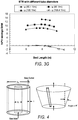
- FIG. 3G is a plot of predicted NPV savings of a feasible XCSA design with coolant tube OD of 0.75" (19 mm) as a function of bed length, as compared to an STR case with various heat transfer area ratio to catalyst volume (or tube ID) for a high selectivity catalyst.
- the expected overall net present value (NPV) improvement over the STR design of all the advantageous XCSA designs with various ⁇ STR values are plotted against the bed length in Figure 3G for the high selectivity catalyst system.
- Figure 3G shows that the NPV improvement of the XCSA design may be expected to be realized for the case with ⁇ STR of 186.4 1/M or tube OD of 0.84" (21.3 mm) in the STR design.
- This example illustrates the predicted impact of a reactor catalyst bed with varying areas in the direction of process flow.
- the ratio of the absolute difference between outlet and inlet area over the catalyst bed length A L of less than 1.3 M indicates where the reactor could be operated with sufficient stability.
- a L is larger than 1.3 M as is the case in the radial flow reactor as shown in Table 5, the reaction is predicted to run away since the flow rate would decrease with bed length and reduce the heat transfer rate. Table 5.
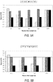
- Figure 5A shows the predicted feasible catalyst-in-shell design with reactant gas flowing parallel (CSA) to the heat transfer surface area with LS catalyst (e.g. Surecat® family as seen Example 1) with a coolant tube OD of 0.75" (19 mm).
- LS catalyst e.g. Surecat® family as seen Example 1
- This case is compared with a 2" (50.8 mm) tube OD (1.83" (46.5 mm) ID) conventional shell and tube reactor with catalyst-in-tube (STR) design.
- the cross flow configuration (XCSA) is expected to provide better heat transfer than the CSA design with lower ⁇ values (lowest ⁇ value required for XCSA design is 22% lower than the STR case).
- the heat transfer coefficient for the XCSA design with cross flow configuration is predicted to be almost twice that of the CSA design.
- the wider feasible catalyst-in-shell design window for the XCSA design is expected to be achieved with a bed length in the range of 6.7 - 11 M as compared to the CSA design with a bed length range of 9-11 M. This may be seen in a comparison of Figure 2A and Figure 5A .
- the expected minimum ⁇ P for the XCSA design is 80% lower than the STR case, as compared to expected minimum ⁇ P for the CSA design, which is only 50% lower than the STR case.
- the predicted minimum reactor weight for the feasible XCSA design is 42% lower than the STR case as compared to the predicted minimum reactor weight for CSA design, which is 31% lower than the STR case.
- Figure 5B also shows the expected advantages of the CSA design with coolant tube OD of 1" (25 mm) as compared to the STR case.
- the overall expected performance of the XCSA design is better than the CSA design with lower ⁇ values, lower ⁇ P, lower reactor weight and better reactor stability.
- Figure 6A shows the predicted feasible catalyst-in-shell design with reactant gas flowing parallel (CSA) to the heat transfer surface area with HS catalyst (e.g. Meteor family as seen in example 1) with a coolant tube OD of 0.75" (19 mm).
- HS catalyst e.g. Meteor family as seen in example 1
- the cross flow configuration of the predicted XCSA provides better heat transfer than a CSA design with lower ⁇ values. Note that the lowest expected ⁇ value required for the XCSA design is 20% lower than the STR case.
- the heat transfer coefficient for an XCSA design with cross flow configuration is predicted to be almost twice that of a CSA design.
- the wider feasible catalyst-in-shell design window for an XCSA design may be achieved with a bed length in the range of 6.0 - 9 M as compared to a CSA design with a bed length range of 7.6-8.8 M. This can be seen in a comparison of Figure 3A and Figure 6A .
- the expected minimum ⁇ P for an XCSA design is 50% lower than the STR case, as compared to the predicted minimum ⁇ P for the CSA design, which is only 37% lower than the STR case.
- the expected minimum reactor weight for the feasible XCSA design is 37% lower than the STR case as compared to predicted minimum reactor weight for CSA design, which is 27% lower than the STR case.
- the STR case depicted is with a 2" (50.8 mm) tube OD (1.83" (46.5 mm) ID) conventional shell and tube reactor with catalyst-in-tube (STR) design.
- FIG. 6B is an evaluation of a predicted catalyst-in-shell side axial flow design with flow parallel to the coolant carrier (CSA) for high selectivity catalyst as compared to the STR case.
- Figure 6B shows the expected advantages of a CSA design with coolant tube OD of 1" (25 mm) as compared to the STR case.
- the overall performance of the XCSA design is predicted to be better than the CSA design with lower ⁇ values, lower ⁇ P, lower reactor weight and better reactor stability.
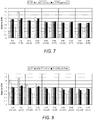
- the expected porosity and catalyst bed density effect on low selectivity EO catalyst system with XCSA design is shown in Figure 7 .
- the porosity ( ⁇ ) is varied from 0.4 to 0.48 as compared to typical value of 0.44.
- Figure 7 shows that for all the porosity ranges and the corresponding catalyst bed density ranges, the XCSA design is expected to always perform better than the corresponding STR case with lower ⁇ P, lower reactor weight, and better stability.
- the predicted preferred range of catalyst bed porosity is within 0.43-0.45.
- FIG. 8 The predicted effect of porosity and catalyst bed density on a high selectivity EO catalyst system with an XCSA design is shown in Figure 8 .
- the porosity ( ⁇ ) is varied from 0.4 to 0.48 as compared to a typical value of 0.435.
- Figure 8 shows that for all the porosity ranges and the corresponding catalyst bed density ranges, the XCSA design is always predicted to perform better than the conventional STR case with lower ⁇ P, lower reactor weight, and better reactor stability.
- the expected preferred range of catalyst bed porosity is within 0.42-0.44.
Landscapes
- Chemical & Material Sciences (AREA)
- Organic Chemistry (AREA)
- Chemical Kinetics & Catalysis (AREA)
- Physics & Mathematics (AREA)
- Fluid Mechanics (AREA)
- Organic Low-Molecular-Weight Compounds And Preparation Thereof (AREA)
- Devices And Processes Conducted In The Presence Of Fluids And Solid Particles (AREA)
- Epoxy Compounds (AREA)
- Catalysts (AREA)
Description
- Currently, reactors for producing ethylene oxide (EO) by partial oxidation of ethylene typically make use of a single conventional fixed-bed shell-tube exchanger (FB) where the catalytic reaction occurs inside the tubes. The fabrication of this type of reactor has reached engineering and transportation limitations due to weight and size factors. It is typical in a conventional design to have 8,000-14,000 tubes with up to 2" (50.8 mm) internal diameter tubes (Dt) arranged in the shell diameter (Ds) with a Ds of 6-9 meters (M) and tube sheets approaching 1.0 ft to 2.0 ft (0.3 to 0.61 m) in thickness. A reactor with an even larger Dt and Ds can theoretically be used to provide a more economically advantageous process given the continually advancing catalyst formulations that are improving average selectivity of 80% to 95% during such a reactor's life time. There is a need for a reactor configuration as an alternative platform for EO catalyst with efficiency higher than 80% that is lower in weight and provides lower pressure drop across the reactor and thus provides higher return on capital investment due to lower operating and capital cost as compared to using a conventional FB reactor.
- In one embodiment, the disclosure relates to a reaction vessel for production of alkylene oxide(s) from partial oxidation of hydrocarbon using a high efficiency heterogeneous catalyst in a fixed bed enclosed within a reaction vessel shell. The reaction vessel comprises a shell having an inflow and an outflow; said shell with a length and width to define a reactor vessel interior volume; a catalyst bed shape defined by said reactor volume, wherein the catalyst bed is such that the cross sectional area at any points A1 and A2, between the in flow and the out flow, separated by a length L1 along the catalyst bed are such that (A2-A1)/L1 is from 0.8 to 1.3m ; said catalyst bed including a catalyst having a selectivity greater than 80%, said catalyst bed defining a process side and having a length less than said shell length and a volume less than said shell volume; a fixed bed outlet zone configured with an average residence time less than or equal to 4 seconds of a gaseous flow from said catalyst bed to a heat exchanger to quench the reactions; said catalyst bed forming a process side of said reaction vessel; and at least one coolant enclosure heat exchanger in said shell interior volume to define a coolant side of the reaction vessel, wherein the coolant enclosure is a tube, said coolant enclosure having an outside surface and an inside surface to define a heat transfer fluid flow path, said coolant enclosure outside surface in contact with said catalyst, said coolant enclosure having an inlet and an outlet for flow of heat transfer fluid through said coolant enclosure inner surface; said coolant enclosure further defining a cooling surface area with the coolant flow cross sectional area ratio to a cooling surface area much less than 1; said coolant side having a pressure greater than or equal to said process side.
- In another embodiment, the disclosure relates to at least one method for producing ethylene oxide from partial oxidation of ethylene using a high efficiency ethylene oxide catalyst in a fixed bed enclosed within a shell of a reaction vessel. In one embodiment, the method may comprise a method for producing gaseous ethylene oxide product from partial oxidationof hydrocarbon using a heterogeneous catalyst in a fixed bed enclosed within a reaction vessel shell, comprising introducing a sufficient amount of gaseous ethylene, oxygen, ballast gas, and catalyst promoter into a reaction vessel having an inflow and an outflow, said vessel having a shell with a length and a width to define a reactor vessel volume; said reactor vessel volume defining a catalyst bed shape; wherein the catalyst bed is such that the cross sectional area at any points A1 and A2, between the in flow and the out flow, separated by a length L1 along the catalyst bed are such that (A2-A1)/L1 is from 0.8 to 1.3m said catalyst bed defining a process side and having a selectivity greater than 80%, said catalyst bed length less than said shell length and having a volume less than said reactor shell volume; circulating a heat transfer fluid through at least one coolant enclosure heat exchanger in said shell interior to define a coolant side of the process; said coolant enclosure equipped with an outside surface and an inside surface; said coolant enclosure outside surface in contact with said catalyst bed and having an inlet and an outlet for the flow of coolant fluid therethrough; said coolant enclosure further defining a cooling surface area with a coolant flow cross sectional area ratio to cooling surface area less than about 1; where the coolant enclosure is a tube; said coolant side having a higher pressure than said process side, and flowing said gaseous ethylene, oxygen, ballast gas and catalyst promoter over said catalyst bed and a gaseous ethylene oxide product through a fixed catalyst bed outlet zone in said reactor vessel; said zone configured with average residence time of less than or equal to 4 seconds of the gaseous ethylene oxide product flow from the outlet of the catalyst bed to a heat exchanger to quench said gaseous ethylene oxide product and flowing said gaseous ethylene oxide product through said reactor vessel outlet.
-
GB472629A -
DE2204539 discloses reactors, of which the shape of the interior is modified by use of a ceramic, refractory lining, and/or by the insertion of a compact, inactive conically-shaped profile with a plane or pyramid-shaped base, the arrangement of shape and form of the lining being correlated so that the cross section of the reaction zone varies in a single direction only, either upwards or downwards, for the purpose of providing the optimum correlation of temperature and time of contact. -
US2002161243 discloses a process for the preparation of maleic anhydride by heterogeneously catalyzed gas-phase oxidation in a reactor with feed for the reaction mixture at one end of the reactor and discharge of the product mixture at the opposite end of the reactor, and with devices for dissipating the heat of reaction which are arranged in the reactor interior and through which a heat-exchange medium flows and which are designed as heat-exchanger plates. -
-
FIG. 1 is a schematic representation of a reaction vessel according to at least one embodiment; -
FIG. 1A is a cross sectional view of the heat transfer fluid enclosure ofFIG. 1 ; -
FIG. 2A is an evaluation of a catalyst-in-shell side reactor design with cross flow (XCSA) for a low selectivity catalyst with a GHSV of 5631 1/hr; -
FIG. 2B is an evaluation of a catalyst-in-shell side reactor design with cross flow (XCSA) for a low selectivity catalyst with a GHSV of 7525 1/hr; -
FIG. 2C is a plot of heat transfer area to catalyst volume ratio ϕ as function of reactor bed length for XCSA reactor designs with various coolant tube diameters and various coolant temperatures yielding different work rates for a low selectivity catalyst; -
FIG. 2D is a plot of heat transfer area to catalyst volume ratio ϕ as function of reactor bed length for XCSA reactor designs at different GHSV values for a low selectivity catalyst; -
FIG. 2E is a plot of heat transfer area to catalyst volume ratio ϕ as function of reactor bed length for XCSA reactor designs with various coolant tube diameters and various coolant temperatures yielding different work rate for a low selectivity catalyst; -
FIG. 2F is a plot of heat transfer area to catalyst volume ratio as function of reactor bed length for XCSA reactor designs with various tube diameters and various coolant temperatures yielding different work rate for a low selectivity catalyst; -
FIG. 2G is a plot of heat transfer area to catalyst volume ratio as function of reactor bed length for XCSA reactor designs with various tube diameters and various coolant temperatures yielding different work rate for a low selectivity catalyst; -
FIG. 2H is a plot of NPV savings of a feasible XCSA design with coolant tube as a function of bed length, as compared to an STR case with various heat transfer area ratios to catalyst volumes (or tube ID) for a low selectivity catalyst; -
FIG. 3A is an evaluation of catalyst-in-shell side reactor design with cross flow (XCSA) for a high selectivity catalyst with a GHSV of 6652 l/hr; -
FIG. 3B is an evaluation of catalyst-in-shell side reactor design with cross flow (XCSA) for a high selectivity catalyst with a GHSV of 8500 1/hr; -
FIG. 3C is a plot of heat transfer area to catalyst volume ratio for high selectivity catalyst as a function of reactor bed length for XCSA reactor designs with various tube diameters; -
FIG. 3D is a plot of heat transfer area to catalyst volume ratio for a high selectivity catalyst as function of reactor bed length for XCSA reactor designs having different GHSV values; -
FIG. 3E is a plot of the heat transfer area to catalyst volume ratio as function of reactor bed length for XCSA reactor designs with various coolant temperatures yielding different work rate for a high selectivity catalyst; -
FIG. 3F is a plot of heat transfer area to catalyst volume ratio as function of reactor bed length for XCSA reactor designs with various coolant temperatures yielding different work rate for a high selectivity catalyst; -
FIG. 3G is a plot of NPV savings of feasible XCSA designs with coolant tubes OD of 0.75" as a function of bed length, as compared to an STR case with various heat transfer area ratio to catalyst volume (or tube ID) for a high selectivity catalyst; -
FIG. 4 is a schematic of radial flow reactor and cone shaped catalyst bed reactor designs; -
FIG. 5A is an evaluation of catalyst-in-shell side axial flow designs with flow parallel to the coolant carrier (CSA) for low selectivity catalyst as compared to an STR case; -
FIG. 5B is an evaluation of catalyst-in-shell side axial flow designs with flow parallel to the coolant carrier (CSA) for low selectivity catalyst as compared to an STR case; -
FIG. 6A is an evaluation of catalyst-in-shell side axial flow designs with flow parallel to the coolant carrier (CSA) for high selectivity catalyst as compared to an STR case; -
FIG. 6B is an evaluation of catalyst-in-shell side axial flow designs with flow parallel to the coolant carrier (CSA) for high selectivity catalyst as compared to STR case; -
FIG. 7 shows the comparison of XCSA reactor designs and conventional reactor designs performance of various ranges of catalyst bed porosity and density for low selectivity catalyst; -
FIG. 8 shows the comparison of an XCSA and conventional reactor designs performance for various ranges of catalyst bed porosity and density for a high selectivity catalyst. - Turning now to the drawings wherein like numbers refer to like structures,
Figure 1 is a schematic representation of areaction vessel 10 having ashell enclosure 12 of a length and width that defines aninternal space 14. The shell is a wall with aninner surface 16 and anouter surface 18, separated by aninsulation layer 20. While the shell is shown schematically, those skilled in the art understand that it could be constructed in any shape desired. The shell is constructed of materials having sufficient strength to contain the internal pressures that arise as the operation of the reaction vessel as is well known in the art. The reaction vessel is further equipped with an inflow 22 for ingress of hydrocarbon or other gaseous raw materials, such as, for example ethylene, oxygen, ballast gases, and gaseous catalyst promoters, into thefeed distribution device 24 and anout flow 26 for effluent gaseous products. In this regard, it is apparent to those skilled in the art that the term "ballast gases" are understood to be, but are not limited to, CO2, CH4, inert gasses such as N2, Helium, Argon, or any other noble gas. Similarly, catalyst promoters may be, but are not limited to, ammonia (NH3), especially for high selectivity catalysts, chlorides, vinyl chloride, ethyl chloride, ethane, and any other suitable gaseous promoter. The in flow and the out flow of the shell are configured to produce an exit gas velocity of from about 5 ft/s, to about 25 ft/s (1.5 to 7.5 m/s), upon exiting the fixed bed reaction zone within the reactor vessel before entering anoutlet pipe 31. The gaseous in flow and out flow have an absolute difference ratio of inlet and outlet flow area over the catalyst bed length from about 0.8 meters to about 1.3 meters and more preferably from about 0.9 to about 1.2 meters. In one embodiment, the shell has an interior pressure during gaseous raw material ingress and gaseous effluent product egress of less than about 350 psig (2.5MPa). - Between the in flow and the out flow, there is a
catalyst bed 28 carried within the shell made of a high or low selectivity catalyst for the oxidation of the gaseous raw material, such as, for example ethylene, to ethylene oxide in a manner to be hereinafter described. The catalyst bed is also known as the process side of the reactor and has a length and a width and defines a volume that is less than the volume of the shell. At any point A1 and A2, between the in flow and the out flow, the catalyst bed has a length L1 such that between the out flow area and the in flow area over the catalyst bed length in between the out flow and the in flow, has an absolute ratio difference as expressed in (A2-A1)/L1 that is less than or equal to about 1.3M. Proximal to the out flow is fixedbed outlet zone 30 to minimize residence time of the effluent product material after exiting the catalytic bed. Generally, the fixed bed outlet zone is configured with an average residence time of less than or about 4 seconds for the gaseous product flow from the outlet of the catalyst bed to a heat exchanger to quench any undesired side reaction further converting alkylene oxide product to other unwanted byproducts such as CO2, H2O, carbon, and CH4. - The catalyst may be selected from the group of catalysts with a lifetime selectivity higher than about 80%. Suitable catalysts may include, without limitation, a low selectivity catalyst such as SureCat® or a high selectivity catalyst such as Meteor®, both available from The Dow Chemical Company. When the catalyst bed is a low selectivity catalyst, the bed has a density in a range from about 960 kg/m3 to about 774 kg/m3, and if a high selectivity catalyst is used as the catalyst bed, the bed has a density in a range from about 837 kg/m3 to about 715 kg/m3.
- The catalyst may be pills having a diffusion length from about 0.02 inches to about 0.07 inches (0.508 mm to 1.778 mm), and more preferably, from about 0.025 inches to about 0.06 inches (0.635 mm to 1.524 mm). The pill diffusion length can be determined by the ratio of the volume of a catalyst pellet to its exterior surface available for reactant penetration and diffusion. A more detailed definition and example can be found on page 476 of "Chemical Reaction Engineering", second edition, Wiley & Sons, 1972. If a low selectivity catalyst is used, the preferred catalyst bed should have a length great than or equal to about 9.5 M, and if a high selectivity catalyst is used as the catalyst bed, the preferred bed should have a length greater than or equal to about 8.5 M.
- The reactor vessel is further equipped with a coolant fluid
enclosure heat exchanger 32 having aninlet 34 and anoutlet 36 for the circulation of heat transfer fluid through the vessel in a manner that may be parallel or cross wise to the direction of gaseous raw material flow through the catalyst bed. As seen inFIG. 1A , the coolant enclosure is generally designated as the coolant side of the reactor, and has anouter surface 38 in contact with the catalyst bed, and aninner surface 40, in contact with the heat transfer fluid. The coolant enclosure defines a coolant surface area with a heat transfer fluid flow cross sectional area ratio to the coolant surface area much less than 1. Moreover, the coolant enclosure surface area ratio to catalyst bed volume is preferably less than or equal to about 187 1/M. The heat transfer fluid may be boiling water in the coolant enclosure at a pressure of up to about 750 psig (5.27 MPa) to maintain temperature in the catalyst bed at a temperature up to about 270°C. In addition, the pressure in the coolant side is preferably greater than the pressure on the process side of the reaction vessel. - Generally, the catalyst bed has an oxidation catalyst of a selectivity greater than about 80%, and, as previously stated, the flow of gaseous raw material through the catalyst bed may be parallel or cross to the direction of flow of heat transfer fluids in the heat transfer fluid enclosure. Accordingly, the coolant enclosure flow may be parallel, helical, perpendicular or in any other direction to the direction of flow of the gaseous raw material through the catalyst bed. The invention is illustrated in particular in Example 4, with various preferred aspects and features illustrated in Examples 1-3 and 5-8.
- The following examples are offered to illustrate various aspects of the present invention. Those skilled in the art understand that they are not to be construed as limiting the scope and spirit of the invention. For all Figures discussed in the Examples, "XCSA" means cross flow catalyst-in-shell reactor; "GHSV" means Gas Hourly Space Velocity, "ϕ" means catalyst volume ratio; "SI" means calculated sensitivity index; "ΔP" means pressure drop and "STR" means conventional reactor with catalyst bed inside the tube.
- A comparison was made between a low selectivity (LS) ethylene oxide catalyst system, such as the Surecat® family and a high selectivity (HS) ethylene oxide catalyst system, such as the Meteor® family, both available from The Dow Chemical Company, with their relevant parameters particle diameter (Dp), porosity (ε), bed density (ρB), beginning of life (BOL) selectivity and typical end of life (EOL) selectivity. Table 1 lists some typical parameters for the low selectivity catalysts and the high selectivity catalysts.
Table 1: Parameters for low and high selectivity catalysts Case Dp ε ρB Selectivity (BOL) Selectivity (EOL) Low Selectivity 5.32 0.44 840 84 80 High Selectivity 6.84 0.44 776 92 88 -
FIG. 2A is an evaluation of a catalyst-in-shell side reactor design with cross flow (XCSA) for low selectivity catalyst with GHSV of 5631 1/hr. A comparison case is shown with a 2" (50.8 mm) tube OD (1.83" (46.5 mm) ID) conventional shell and tube reactor with catalyst-in-tube (STR) design. For low selectivity (LS) catalysts with range of 80 to 86% such as disclosed in Example 1 above, a catalyst-in-shell with cross flow (XCSA) design with 0.75" (19 mm) coolant tube with GHSV of 5631 1/hr will show advantages over the conventional shell and tube reactor with catalyst-in-tube (STR) design with 2" (50.8 mm) tube OD (with 1.83" (46.5 mm) ID). The STR case tube ID is such that the heat transfer area over catalyst volume ratio (ϕ) is 86 1/M. In this case, the XCSA design will show improved stability as shown by the larger calculated sensitivity index (SI), lower weight and lower pressure drop (ΔP) and even lower ϕ with XCSA reactor bed length between 6.7 and 11.7 M as shown inFigure 2A . It is also apparent that the ΔP decreases with a lower bed length while in contrast the reactor weight increases with lower bed length. -
FIG. 2B is an evaluation of catalyst-in-shell side reactor design with cross flow (XCSA) for low selectivity catalyst with GHSV of 7525 1/hr. A comparison case is shown with 2" (50.8 mm) tube OD (1.83" (46.5 mm) ID) conventional shell and tube reactor with catalyst-in-tube (STR) design. The reactor ofFigure 2B will show a similar improvement as the reactor ofFigure 2A by using an XCSA concept with a GHSV of 7531 1/hr. Table 2 shows the detailed calculation results from LS catalyst and it also shows that similar improvement may be expected to be achieved in XCSA designs over STR designs using 2" (50.8 mm) OD tubes (ϕ=86 1/M and 1.83" (46.5 mm) ID) by using different coolant tubes OD while keeping the catalyst bed volume and other operating conditions (coolant temperature, GHSV, production rate, inlet pressure, inlet gas temperature) similar to STR cases and with SI, EO outlet concentration, and selectivity similar to or better than those in STR cases. In addition, Table 2 also shows that significant improvement in the ϕ (and thus reactor weight) may be obtainable at various coolant tube OD (e.g. XCSA 2, 5 and 8) while still providing lower ΔPs than that of STR cases. Note also that ΔP can be much lower than that in STR cases for various coolant tubes OD while still maintaining lower weight ratio (e.g. case XCSA Table 2: Evaluation of catalyst-in-shell side reactor design with cross flow (XCSA) and comparison with conventional fixed bed reactor for lower selectivity catalyst for GHSV of 5631 1/hr. Coolant tubes having OD of 0.75 in (19.1 mm), 1 in (25.4 mm) and 1.25 in (31.8 mm) are used. Case STR XCSA- 1 XCSA- 2 XCSA- 3 XCSA- 4 XCSA- 5 XCSA- 6 XCSA- 7 XCSA-8 XCSA-9 ϕ (1/m) 85.96 81 72.0 87.2 78.2 68.7 86 75.6 69 86 coolant tube OD (in) N/A 0.75 0.75 0.75 1 1 1 1.25 1.25 1.25 ΔP psig 57.62 17.76 39.71 10.54 22.7 49.8 11.57 28 49.7 12.4 (ΔP KPa) 397.3 122.5 273.8 72.7 156.5 343.4 79.8 193.1 342.7 85.5 Weight ratio 1 0.69 0.62 0.75 0.69 0.61 0.76 0.68 0.62 0.76 Ds ratio 1 0.99 0.86 1.09 0.99 0.86 1.13 0.99 0.89 1.16 L ratio 1 0.69 0.89 0.58 0.75 0.96 0.6 0.85 0.95 0.61 -
FIG. 2C is a plot showing the prediction of heat transfer area to catalyst volume ratio ϕ as a function of reactor bed length for XCSA reactor design with various coolant tube diameters and various coolant temperatures yielding different work rates (work rate is indicated in legend in lbs/ft3-hr) for low selectivity catalyst. The ΔP, 1/SI and weight ratio with respect to STR cases (STR with 2" (50.8 mm) OD and Dti = 1.83" (46.5 mm)) are also plotted as a function of bed length.Figure 2C also shows the prediction that the XCSA design is advantageous over STR designs with ϕSTR=86 1/M for different coolant temperatures and hence different production rates. More importantly,Figure 2C also shows the prediction that the ϕ of XCSA design concept is always lower than or equal to ϕSTR of 86 1/M when the catalyst bed length is equal to or larger than 6.5 M. In addition, this is also predicted to be true for all coolant tubes OD of 0.6" to 1.5" (15 mm to 38 mm) and at various coolant temperatures. Note thatFigure 2C also demonstrates that the XCSA design can provide lower weight, higher stability, and lower ΔP with bed length up to about an 11 M bed than that of the STR design. -
FIG. 2D is plot showing prediction of heat transfer area to catalyst volume ratio ϕ as a function of reactor bed length for XCSA reactor design at different GHSV values for a low selectivity catalyst. The ΔP, 1/SI and weight ratio with STR cases (STR with 2" (50.8 mm) OD and Dti = 1.83" (46,5 mm)) are also plotted as a function of bed length.Figure 2D illustrates the predicted advantage of an XCSA design with lower ϕ for various GHSV values as compared to the STR case design with ϕSTR=86 1/M. As shown above in reference to Table 2, both the predicted reactor ΔP and stability are also advantageous over an STR design of up to 11 M bed length. -
FIG. 2E is a plot showing a prediction of heat transfer area to catalyst volume ratio ϕ as a function of reactor bed length for XCSA reactor design with various coolant tube diameters and various coolant temperatures yielding different work rate (work rate is indicated in legend in lbs/ft3-hr) for a low selectivity catalyst (1 lb/ft3-hr = 16 Kg/m3-hr). The predicted ΔP, 1/SI and weight ratio with an STR case (conventional reactor with Dti = 0.84" (21.3 mm)) are also plotted as a function of bed length. As is the case withFigures 2A through 2D ,Figure 2E demonstrates the predicted advantages of an XCSA design concept with lower ϕ as compared to the STR design with tube OD of 0.84" (21.3 mm) and ϕSTR=186.4 1/M, at different coolant temperature and XCSA design coolant tube with OD of 0.75" (19 mm) and 1.5' (38.1 mm) with bed length in the range of 6.0 M to 12 M. This also illustrates that the XCSA design ofFigure 2E is expected to show better expected stability, requires lower expected reactor weight and ΔP at the same operating conditions as STR with tube OD of 0.84" (21.3 mm) in the range of 6.5M to 11M bed length. -
FIG. 2F is a plot showing a prediction of heat transfer area to catalyst volume ratio as a function of reactor bed length for XCSA reactor design with various tube diameters and various coolant temperatures yielding different work rate (work rate is indicated in legend in lbs/ft3-hr) for a low selectivity catalyst (1 lb/ft3-hr = 16 Kg/m3-hr). The expected ΔP, 1/SI and weight ratio with STR case (conventional reactor with tube ID of 1.5" (38 mm)) are also plotted as a function of bed length. A similar trend to that indicated inFigures 2A through E is illustrated inFigure 2F for the XCSA design as compared to STR design case with tube ID of 1.5" (38 mm)and ϕSTR=105.0 1/M, at different XCSA coolant tube ODs and coolant temperatures.Figure 2F also depicts the expected XCSA advantageous bed length range of 5.8 M to 12.0 M. -
FIG. 2G is a plot showing a prediction of heat transfer area to catalyst volume ratio as a function of reactor bed length for an XCSA reactor design with various tube diameters and various coolant temperatures yielding different work rate (work rate is indicated in legend in lbs/ft3-hr) for a low selectivity catalyst (1 lb/ft3-hr = 16 Kg/m3-hr). The expected ΔP, 1/SI and weight ratio with STR case (conventional reactor with tube ID of 2.17" (55 mm)) are also plotted as a function of bed length. A similar trend as seen inFigures 2A through 2F is also illustrated inFigure 2G for the XCSA design as compared to the STR case design with tube ID of 2.17" (55 mm) or ϕSTR=72.6 1/M, at different coolant tube OD and coolant temperature.Figure 2G also depicts the expected XCSA advantageous bed length range of 7.5 M to 11.5 M. - Finally, an expected overall net present value (NPV) improvement over the STR design of all the advantageous XCSA designs with various ϕSTR values is plotted against the bed length in
Figure 2H . The expected overall NPV improvement expected from savings in operating cost (Operating ΔP) and capital cost (approximately proportional to reactor weight) as compared to STR case with tube OD of 2" (50.8 mm), shows a maximum along the bed length range. For lower reactor bed lengths, NPV savings from operating costs are expected to increase, due to lower pressure drop across the reactor, and higher bed length savings from capital investment are expected to be higher due to lower reactor weight. This gives rise to the highest expected NPV savings at an intermediate length range from 8 to 9.5 M. More importantlyFigure 2H also shows that the expected NPV improvement of the XCSA design may begin to be realized for the case with ϕSTR of 186.4 1/M or tube OD of 0.84" (21 mm) in the STR design. -
FIG. 3A is a predicted evaluation of a catalyst-in-shell side reactor design with cross flow (XCSA) for a high selectivity catalyst with a GHSV of 6652 1/hr. The STR case is using a 2" (50.8 mm) tube OD (1.83" (46.5 mm) ID) for a conventional shell and tube reactor with catalyst-in-tube design. As depicted therein, for a high selectivity (HS) catalyst with range of 86 to 95%, the catalyst on the shell side with cross flow (XCSA) design with 0.75" (109 mm) coolant tube with GHSV 6652 1/hr is expected to show advantages over the conventional shell and tube reactor with catalyst-in-tube (STR) design with 2" tube OD (1.83" (46.5 mm) ID). The STR case has the same ϕ =86 1/M, as seen in Example 2.Figure 3A depicts that the expected XCSA design requires lower ϕ than the STR design and also shows predicted improved stability, lower reactor weight and lower pressure drop (ΔP) with reactor bed length between 6M and 9M. - Similar improvements are also expected for a case with different GHSV as shown in
Figure 3B. FIG. 3B is an evaluation of a predicted catalyst-in-shell side reactor design with cross flow (XCSA) for a high selectivity (HS) catalyst (Meteor) with a GHSV of 8500 1/hr. The STR case is with a 2" (50.8 mm) tube OD (1.83" (46.5 mm) ID) conventional shell and tube reactor with catalyst-in-tube design. Table 3 shows the detailed calculations expected results for HS catalyst and also shows that similar improvement can be expected to be achieved in an XCSA design over an STR design by using different coolant tube OD's while keeping catalyst volume and other operating conditions (coolant Temperature, GHSV, production rate, inlet pressure, inlet gas temperature) similar to the STR case. Table 3 also shows that significant improvement in the ϕ (thus reactor weight) is expected to be obtained at various coolant tube OD's (e.g. XCSA e.g. case XCSA Table 3: Catalyst-in-shell side reactor designs with cross flow (XCSA) and comparison with conventional fixed bed reactor for high selectivity catalyst with GHSV of 6652 1/hr. Coolant tubes having OD of 0.75 in (19.1 mm), 1 in (25.4 mm) and 1.25 in (31.8 mm) are used. Case STR XCSA-1 XCSA-2 XCSA-3 XCSA-4 XCSA-5 XCSA-6 XCSA-7 XCSA-8 XCSA-9 Φ, Heat transfer/cat vol (1/M) 86 76 70 86.0 75 71 72.5 75 69 76 coolant tube OD (in) N/A 0.75 0.75 0.75 1 1 1 1.25 1.25 1.25 ΔP (psig) 37.7 29.9 41.5 15 14.52 33.45 21.48 18.43 37.28 12.59 ΔP (KPa) 259.9 206.2 286.1 103.4 100.1 230.6 148.1 127.1 257.0 86.80 Weight ratio 1 0.68 0.63 0.77 0.71 0.66 0.68 0.72 0.65 0.74 Ds ratio 1 0.88 0.83 1.00 1 0.87 0.93 1.00 0.88 1.07 L ratio 1 0.93 1.03 0.74 0.78 1.02 0.89 0.84 1.05 0.74 -
FIG. 3C is a plot showing a prediction of heat transfer area to catalyst volume ratio for high selectivity catalyst as a function of reactor bed length for an XCSA reactor design with various tubes. Work rate is indicated in legend in lbs/ft3-hr (1 lb/ft3-hr = 16 Kg/m3-hr). The expected ΔP, 1/SI and weight ratio with STR case tube OD's of 2" (50.8 mm) (ID of 1.83" (46.5 mm)) are also plotted as a function of bed length.Figure 3C shows that various XCSA designs are expected to be advantageous over an STR design with ϕSTR=86 1/M for different coolant temperatures and hence different production rates.Figure 3C also shows that the ϕ of an XCSA design concept is always lower than or equal to ϕSTR of 86 1/M when bed length is equal to or larger than 6.2 M and this is valid for all coolant tubes OD of 0.75" to 1.5" (19 mm to 38 mm) and at various coolant temperatures.Figure 3C also demonstrates that an XCSA design concept is expected to have lower weight, stability, and ΔP up to a bed length of about 9.5 M as compared to an STR design. As shown above, both the predicted reactor ΔP and stability are also advantageous over an STR design up to 9.5 M bed length. -
FIG. 3D is a plot showing a prediction of heat transfer area to catalyst volume ratio as function of reactor bed length for an XCSA reactor design at different GHSV values. The expected ΔP, 1/SI and weight ratios with the STR case (conventional reactor with Dti =1.83" (46.5 mm)) are also plotted as a function of bed length for a high selectivity catalyst, such as Meteor.Figure 3D illustrates the expected advantage of an XCSA design with lower ϕ for various GHSV values as compared to an STR case design with ϕSTR=86 1/M. As shown above, both the expected reactor ΔP and stability are also advantageous over an STR design up to 9.5 M bed length. -
FIG. 3E is a plot showing a prediction of heat transfer area to catalyst volume ratio as function of reactor bed length for an XCSA reactor design with various coolant temperatures yielding different work rate for a high selectivity catalyst. Work rate is indicated in legend in lbs/ft3-hr. The expected ΔP, 1/SI and weight ratio with an STR case (conventional reactor with tube ID of 0.84" (21.3 mm)) are also plotted as a function of bed length.Figure 3E is similar toFigures 3A through 3D , and demonstrates the predicted advantages of an XCSA design concept with lower ϕ as compared to an STR case design with tube OD of 0.84" (21.3 mm) and ϕSTR=186.4 1/M, at different coolant temperature and design coolant tubes with OD of 0.75" with bed length in the range of 7.5 M to 9.0 M.Figure 3E also illustrates that the XCSA design shows better expected stability, requires lower reactor weight and ΔP at the same operating conditions as an STR with tube OD of 0.84" (21.3 mm) in the range of 7.5 to 9.8 M bed length. -
FIG. 3F is a plot showing a prediction of heat transfer area to catalyst volume ratio as a function of reactor bed length for an XCSA reactor design with various coolant temperatures yielding different work rates for a high selectivity catalyst. Work rate is indicated in legend in lbs/ft3-hr (1 lb/ft3-hr = 16 Kg/m3-hr). The expected ΔP, 1/SI and weight ratio with the STR case (conventional reactor with tube ID of 1.5" (38 mm)) are also plotted as a function of bed length.Figure 3F is similar toFigures 3A through 3E , and sets forth the predicted advantages of an XCSA design as compared to an STR design case with tube ID of 1.5" (38 mm) and ϕSTR=105 1/M, at different XCSA coolant temperatures.Figure 3F also depicts the XCSA is expected to have an advantageous bed length range of 7.8 M to 9.0 M. -
FIG. 3G is a plot of predicted NPV savings of a feasible XCSA design with coolant tube OD of 0.75" (19 mm) as a function of bed length, as compared to an STR case with various heat transfer area ratio to catalyst volume (or tube ID) for a high selectivity catalyst. The expected overall net present value (NPV) improvement over the STR design of all the advantageous XCSA designs with various ϕSTR values are plotted against the bed length inFigure 3G for the high selectivity catalyst system. The expected overall NPV improvement coming from savings in operating cost (proportional to the operating ΔP) and capital cost (proportional to the reactor weight) as compared to base case STR with tube OD of 2" (50.8 mm), shows a maximum along the bed length range. For lower reactor bed length, expected NPV savings from operating costs are higher as seen inFigure 3G , and for higher bed length, predicted savings from capital investments are higher due to lower reactor weight, as seen inFigure 3F . This gives rise to a highest expected NPV at an intermediate length range from 7.0 to 8.5 m. More importantlyFigure 3G also shows that the NPV improvement of the XCSA design may be expected to be realized for the case with ϕSTR of 186.4 1/M or tube OD of 0.84" (21.3 mm) in the STR design. - This example illustrates the predicted impact of a reactor catalyst bed with varying areas in the direction of process flow. The ratio of the absolute difference between outlet and inlet area over the catalyst bed length AL of less than 1.3 M indicates where the reactor could be operated with sufficient stability. For a tubular type of reactor this can be represented with a truncated cone shape catalyst bed with an angle of 9° as shown in
Figure 4 . This 9° angle represents the predicted expansion in the shell and tubes such that heat transfer area to catalyst volume is maintained at 67 (1/M). When AL is larger than 1.3 M as is the case in the radial flow reactor as shown in Table 5, the reaction is predicted to run away since the flow rate would decrease with bed length and reduce the heat transfer rate.Table 5. Design variables of radial flow design and variable area design at constant catalyst volume with coolant tube OD of 0.75" (19 mm)and ϕ = 67 1/M. Case Radial Flow Design Varying area axial flow design (9°) Radial Flow Design Bed length, L (M) 5.5 6.4 4.5 Di for Radial design (M) 1 N/A 2 AL (M) 19.2 1.3 18.9 -
Figure 5A shows the predicted feasible catalyst-in-shell design with reactant gas flowing parallel (CSA) to the heat transfer surface area with LS catalyst (e.g. Surecat® family as seen Example 1) with a coolant tube OD of 0.75" (19 mm). This case is compared with a 2" (50.8 mm) tube OD (1.83" (46.5 mm) ID) conventional shell and tube reactor with catalyst-in-tube (STR) design. The heat transfer area to catalyst volume required for the CSA design is expected to be the same as the STR case (ϕ= 86 1/M). The cross flow configuration (XCSA) is expected to provide better heat transfer than the CSA design with lower ϕ values (lowest ϕ value required for XCSA design is 22% lower than the STR case). The heat transfer coefficient for the XCSA design with cross flow configuration is predicted to be almost twice that of the CSA design. The wider feasible catalyst-in-shell design window for the XCSA design is expected to be achieved with a bed length in the range of 6.7 - 11 M as compared to the CSA design with a bed length range of 9-11 M. This may be seen in a comparison ofFigure 2A andFigure 5A . The expected minimum ΔP for the XCSA design is 80% lower than the STR case, as compared to expected minimum ΔP for the CSA design, which is only 50% lower than the STR case. The predicted minimum reactor weight for the feasible XCSA design is 42% lower than the STR case as compared to the predicted minimum reactor weight for CSA design, which is 31% lower than the STR case. Similarly,Figure 5B also shows the expected advantages of the CSA design with coolant tube OD of 1" (25 mm) as compared to the STR case. The overall expected performance of the XCSA design is better than the CSA design with lower ϕ values, lower ΔP, lower reactor weight and better reactor stability. -
Figure 6A shows the predicted feasible catalyst-in-shell design with reactant gas flowing parallel (CSA) to the heat transfer surface area with HS catalyst (e.g. Meteor family as seen in example 1) with a coolant tube OD of 0.75" (19 mm). The heat transfer area to catalyst volume required for the CSA design is the same as the STR case (ϕ = 86 1/M). The cross flow configuration of the predicted XCSA provides better heat transfer than a CSA design with lower ϕ values. Note that the lowest expected ϕ value required for the XCSA design is 20% lower than the STR case. The heat transfer coefficient for an XCSA design with cross flow configuration is predicted to be almost twice that of a CSA design. The wider feasible catalyst-in-shell design window for an XCSA design may be achieved with a bed length in the range of 6.0 - 9 M as compared to a CSA design with a bed length range of 7.6-8.8 M. This can be seen in a comparison ofFigure 3A andFigure 6A . The expected minimum ΔP for an XCSA design is 50% lower than the STR case, as compared to the predicted minimum ΔP for the CSA design, which is only 37% lower than the STR case. The expected minimum reactor weight for the feasible XCSA design is 37% lower than the STR case as compared to predicted minimum reactor weight for CSA design, which is 27% lower than the STR case. The STR case depicted is with a 2" (50.8 mm) tube OD (1.83" (46.5 mm) ID) conventional shell and tube reactor with catalyst-in-tube (STR) design. -
FIG. 6B is an evaluation of a predicted catalyst-in-shell side axial flow design with flow parallel to the coolant carrier (CSA) for high selectivity catalyst as compared to the STR case. As is the case withFigure 6A, Figure 6B shows the expected advantages of a CSA design with coolant tube OD of 1" (25 mm) as compared to the STR case. The overall performance of the XCSA design is predicted to be better than the CSA design with lower ϕ values, lower ΔP, lower reactor weight and better reactor stability. - The expected porosity and catalyst bed density effect on low selectivity EO catalyst system with XCSA design is shown in
Figure 7 . The porosity (ε) is varied from 0.4 to 0.48 as compared to typical value of 0.44.Figure 7 shows that for all the porosity ranges and the corresponding catalyst bed density ranges, the XCSA design is expected to always perform better than the corresponding STR case with lower ΔP, lower reactor weight, and better stability. The predicted preferred range of catalyst bed porosity is within 0.43-0.45. - The predicted effect of porosity and catalyst bed density on a high selectivity EO catalyst system with an XCSA design is shown in
Figure 8 . The porosity (ε) is varied from 0.4 to 0.48 as compared to a typical value of 0.435.Figure 8 shows that for all the porosity ranges and the corresponding catalyst bed density ranges, the XCSA design is always predicted to perform better than the conventional STR case with lower ΔP, lower reactor weight, and better reactor stability. The expected preferred range of catalyst bed porosity is within 0.42-0.44. - Those skilled in the art recognize that the words used in this specification are words of description and not words of limitation. Many variations and modifications will be apparent to those skilled in the art upon a reading of this application without departing from the scope of the invention as set forth in the appended claims.
Claims (15)
- A method for producing gaseous ethylene oxide product from partial oxidation of hydrocarbon using a heterogeneous catalyst in a fixed bed enclosed within a reaction vessel shell, comprising:introducing a sufficient amount of gaseous ethylene, oxygen, ballast gas, and catalyst promoter into a reaction vessel having an inflow and an outflow, said vessel having a shell with a length and a width to define a reactor vessel volume; said reactor vessel volume defining a catalyst bed shape; wherein the catalyst bed is such that the cross sectional areas A1 and A2 at any two points of the catalyst bed separated by a length L1 between the in flow and the out flow are such that (A2-A1)/L1 is from 0.8 to 1.3m, said catalyst bed defining a process side and having a selectivity greater than 80%, said catalyst bed having a length less than said shell length and having a volume less than said reactor shell volume;circulating a heat transfer fluid through at least one coolant enclosure heat exchanger in said shell interior to define a coolant side of the process; said coolant enclosure equipped with an outside surface and an inside surface; said coolant enclosure outside surface in contact with said catalyst bed and having an inlet and an outlet for the flow of coolant fluid therethrough; said coolant enclosure further defining a cooling surface area with a coolant flow cross sectional area ratio to cooling surface area less than about 1; where the coolant enclosure is a tube; said coolant side having a higher pressure than said process side, and flowing said gaseous ethylene, oxygen, ballast gas and catalyst promoter over said catalyst bed and a gaseous ethylene oxide product through a fixed catalyst bed outlet zone in said reactor vessel; said zone configured with average residence time of less than or equal to 4 seconds of the gaseous ethylene oxide product flow from the outlet of the catalyst bed to a heat exchanger to quench said gaseous ethylene oxide product and flowing said gaseous ethylene oxide product through said reactor vessel outlet.
- The method of claim 1, wherein the flow of gaseous ethylene, oxygen, ballast gas, and catalyst promoters over the catalyst bed is crosswise to said heat transfer fluid flow through said coolant enclosure.
- The method of claim 1, wherein said inflow for ethylene, oxygen, ballast gas, and catalyst promoters, and said outflow for ethylene oxide are configured to produce an exit gas velocity of at least about 5 ft/s (1.5 m/s) upon exiting the fixed catalyst bed within the reactor vessel outlet before entering an outlet pipe.
- The method of claim 1, wherein said total coolant surface area ratio to catalyst bed volume is less than or equal to about 187 (1/meter).
- The method of claim 1, wherein said heat exchange fluid is boiling water in said coolant enclosure at a pressure up to about 750 psig (5.27MPa) to maintain temperature in the catalyst bed up to about 270°C.
- The method of claim 1, wherein the shell has an interior pressure during ingress of said gaseous ethylene, oxygen and gaseous product egress of less than about 350 psig (2.52MPa).
- The method of claim 1, wherein the coolant enclosure cross sectional area is equivalent to at least one tube having an inner diameter in the range of 0.2" to 1.8" (5 to 46 mm).
- The method of claim 1, wherein said inflow for ethylene and said outflow for ethylene oxide containing effluent product are configured to produce a gas velocity exiting the fixed bed in the range of from about 15 ft/s to about 25 ft/s (4.6 to 7.6 m/s).
- The method of claim 1, wherein said inlet gas comprising ethylene, oxygen, ballast gas and promoters, and said ethylene oxide effluent products outlet have an absolute difference ratio of the inlet and outlet flow area over said catalyst bed length of from about 0.9 meter to about 1.2 meter.
- The method of claim 1, wherein the flow of gaseous ethylene, oxygen, ballast gases and catalyst promoter through the catalyst bed is parallel to said heat transfer fluid flow through said coolant enclosure.
- The method of claim 1, wherein said catalyst is comprised of pills having a diffusion length of from about 0.02 inches to about 0.07 inches (0.5 to 1.8 mm).
- The method of claim 1, wherein said catalyst bed length is larger than about 9.5 meter.
- The method of claim 1, wherein said catalyst bed length is larger than about 8.5 meter.
- The method of claim 1, wherein said catalyst bed has a porosity in the range of from about 0.38 to about 0.49.
- A reaction vessel for production of gaseous alkylene oxide from partial oxidation of hydrocarbon, catalyst promoter and ballast gas using a high efficiency heterogeneous catalyst in a fixed bed enclosed within a reaction vessel shell, comprising:a shell having an inflow and an outflow; said shell with a length and width to define a reactor vessel interior volume;a catalyst bed shape defined by said reactor volume, wherein the catalyst bed is such that the cross sectional areas A1 and A2 at any two points of the catalyst bed separated by a length L1 between the in flow and the out flow, are such that (A2-A1)/L1 is from 0.8 to 1.3m ; said catalyst bed including a catalyst having a selectivity greater than about 80%, said catalyst bed defining a process side and having a length less than said shell length and a volume less than said shell volume; a fixed bed outlet zone configured with an average residence time less than or equal to 4 seconds of a gaseous flow from said catalyst bed to a heat exchanger to quench the reactions; said catalyst bed forming a process side of said reaction vessel; andat least one coolant enclosure heat exchanger in said shell interior volume to define a coolant side of the reaction vessel, wherein the coolant enclosure is a tube, said coolant enclosure having an outside surface and an inside surface to define a heat transfer fluid flow path, said coolant enclosure outside surface in contact with said catalyst, said coolant enclosure having an inlet and an outlet for flow of heat transfer fluid through said coolant enclosure inner surface; said coolant enclosure further defining a cooling surface area with the coolant flow cross sectional area ratio to a cooling surface area much less than 1; said coolant side having a pressure greater than or equal to said process side.
Applications Claiming Priority (2)
| Application Number | Priority Date | Filing Date | Title |
|---|---|---|---|
| US31467710P | 2010-03-17 | 2010-03-17 | |
| PCT/US2011/028763 WO2011116157A1 (en) | 2010-03-17 | 2011-03-17 | Catalytic fixed bed reactor for producing ethylene oxide by partial oxidation of ethylene |
Publications (2)
| Publication Number | Publication Date |
|---|---|
| EP2547434A1 EP2547434A1 (en) | 2013-01-23 |
| EP2547434B1 true EP2547434B1 (en) | 2020-01-08 |
Family
ID=43899617
Family Applications (1)
| Application Number | Title | Priority Date | Filing Date |
|---|---|---|---|
| EP11712373.7A Active EP2547434B1 (en) | 2010-03-17 | 2011-03-17 | Catalytic fixed bed reactor and method for producing ethylene oxide by partial oxidation of ethylene |
Country Status (6)
| Country | Link |
|---|---|
| US (2) | US9073034B2 (en) |
| EP (1) | EP2547434B1 (en) |
| CN (1) | CN102905782B (en) |
| CA (1) | CA2793500C (en) |
| TW (1) | TWI496618B (en) |
| WO (1) | WO2011116157A1 (en) |
Families Citing this family (4)
| Publication number | Priority date | Publication date | Assignee | Title |
|---|---|---|---|---|
| CN104650006B (en) * | 2013-11-18 | 2017-10-17 | 岳阳昌德化工实业有限公司 | A kind of olefin epoxidation method |
| WO2017089935A1 (en) | 2015-11-23 | 2017-06-01 | Sabic Global Technologies B.V. | Structural catalyst with internal heat transfer system for exothermic and endothermic reactions |
| NL2026371B1 (en) * | 2020-08-28 | 2022-04-29 | Catip B V | Catalytic reactor with improved properties |
| EP4059595A1 (en) * | 2021-03-15 | 2022-09-21 | Linde GmbH | Production of ethylene by oxidative dehydrogenation of ethane |
Family Cites Families (33)
| Publication number | Priority date | Publication date | Assignee | Title |
|---|---|---|---|---|
| GB472629A (en) | 1936-01-24 | 1937-09-24 | Distillers Co Yeast Ltd | Improvements in process and apparatus for carrying out exothermic reactions |
| US3252505A (en) * | 1962-06-22 | 1966-05-24 | Chrysler Corp | Rotary heat exchanger |
| DE2204539A1 (en) * | 1972-02-01 | 1973-08-23 | Inst De Cercetari Pentru Chimi | Chemical reactors - for end othermic or exothermic reactions carried out in presence of solid or liquid catalyst |
| US4916243A (en) | 1979-03-20 | 1990-04-10 | Union Carbide Chemicals And Plastics Company Inc. | New catalyst composition and process for oxidation of ethylene to ethylene oxide |
| SU980802A1 (en) * | 1981-01-04 | 1982-12-15 | Предприятие П/Я В-8585 | Contact apparatus with stationary granular material bed |
| US4379134A (en) | 1981-02-13 | 1983-04-05 | Union Carbide Corporation | Process of preparing high purity alumina bodies |
| AT382393B (en) * | 1984-06-18 | 1987-02-25 | Voest Alpine Ag | REEL |
| US5059481A (en) | 1985-06-17 | 1991-10-22 | Viskase Corporation | Biaxially stretched, heat shrinkable VLDPE film |
| GB2190855A (en) | 1986-05-28 | 1987-12-02 | Shell Int Research | Process for the preparation of a silver-containing catalyst |
| US4808738A (en) | 1986-10-31 | 1989-02-28 | Shell Oil Company | Ethylene oxide process |
| US4761394A (en) | 1986-10-31 | 1988-08-02 | Shell Oil Company | Ethylene oxide catalyst and process for preparing the catalyst |
| US4766105A (en) | 1986-10-31 | 1988-08-23 | Shell Oil Company | Ethylene oxide catalyst and process for preparing the catalyst |
| US4820675A (en) | 1986-10-31 | 1989-04-11 | Shell Oil Company | Ethylene oxide catalyst & process for preparing the catalyst |
| US4833261A (en) | 1986-10-31 | 1989-05-23 | Shell Oil Company | Ethylene oxide process |
| US4908343A (en) | 1987-02-20 | 1990-03-13 | Union Carbide Chemicals And Plastics Company Inc. | Catalyst composition for oxidation of ethylene to ethylene oxide |
| CN1009437B (en) | 1988-02-03 | 1990-09-05 | 中国石油化工总公司 | High-efficiency silver catalyst for oxidizing ethylene into epoxy ethane |
| GB8810006D0 (en) * | 1988-04-27 | 1988-06-02 | Shell Int Research | Process for preparation of ethylene oxide |
| CA1337722C (en) | 1989-04-18 | 1995-12-12 | Madan Mohan Bhasin | Alkylene oxide catalysts having enhanced activity and/or stability |
| US5187140A (en) | 1989-10-18 | 1993-02-16 | Union Carbide Chemicals & Plastics Technology Corporation | Alkylene oxide catalysts containing high silver content |
| US5102848A (en) | 1990-09-28 | 1992-04-07 | Union Carbide Chemicals & Plastics Technology Corporation | Catalyst composition for oxidation of ethylene to ethylene oxide |
| JP2720124B2 (en) | 1990-10-12 | 1998-02-25 | ユニオン・カーバイド、ケミカルズ、アンド、プラスチックス、テクノロジー、コーポレーション | Alkylene oxide catalysts with enhanced activity and / or stability |
| JP2778878B2 (en) | 1991-09-12 | 1998-07-23 | 株式会社日本触媒 | Method for producing ethylene oxide |
| US5384302A (en) | 1993-09-08 | 1995-01-24 | Norton Chemical Process Products Corp. | Catalyst carrier |
| JPH11139802A (en) * | 1997-11-04 | 1999-05-25 | Aisin Seiki Co Ltd | Reformer for fuel cell |
| US6309768B1 (en) * | 1999-07-02 | 2001-10-30 | International Fuel Cells Llc | Process for regenerating a carbon monoxide oxidation reactor |
| DE10000584A1 (en) | 2000-01-10 | 2001-07-12 | Basf Ag | Process for the catalytic gas phase oxidation to maleic anhydride |
| DK1358441T4 (en) * | 2001-02-08 | 2014-11-03 | Scient Design Co | Reactor and radiator design for exothermic reactions |
| US6831037B2 (en) | 2002-02-25 | 2004-12-14 | Saint-Gobain Norpro Corporation | Catalyst carriers |
| MY146505A (en) * | 2003-02-28 | 2012-08-15 | Shell Int Research | A method of manufacturing ethylene oxide |
| JP2006131562A (en) * | 2004-11-08 | 2006-05-25 | Sumitomo Chemical Co Ltd | Propylene oxide production method |
| US7459589B2 (en) * | 2005-12-22 | 2008-12-02 | Shell Oil Company | Process for the preparation of an alkylene glycol |
| CN101397282B (en) * | 2007-09-28 | 2011-04-20 | 中国石油化工股份有限公司 | Method for preparing epoxypropane |
| CN201301294Y (en) * | 2008-11-03 | 2009-09-02 | 山东科技大学 | Tube array type epoxy ethane reactor with quench zone |
-
2011
- 2011-03-17 CA CA2793500A patent/CA2793500C/en active Active
- 2011-03-17 WO PCT/US2011/028763 patent/WO2011116157A1/en not_active Ceased
- 2011-03-17 EP EP11712373.7A patent/EP2547434B1/en active Active
- 2011-03-17 US US13/635,642 patent/US9073034B2/en active Active
- 2011-03-17 TW TW100109091A patent/TWI496618B/en active
- 2011-03-17 CN CN201180023494.XA patent/CN102905782B/en active Active
-
2015
- 2015-06-01 US US14/726,685 patent/US10010856B2/en active Active
Non-Patent Citations (1)
| Title |
|---|
| None * |
Also Published As
| Publication number | Publication date |
|---|---|
| WO2011116157A1 (en) | 2011-09-22 |
| CN102905782B (en) | 2015-04-08 |
| TW201143892A (en) | 2011-12-16 |
| TWI496618B (en) | 2015-08-21 |
| US20150336064A1 (en) | 2015-11-26 |
| CN102905782A (en) | 2013-01-30 |
| US9073034B2 (en) | 2015-07-07 |
| US10010856B2 (en) | 2018-07-03 |
| EP2547434A1 (en) | 2013-01-23 |
| CA2793500C (en) | 2019-01-15 |
| CA2793500A1 (en) | 2011-09-22 |
| US20130144073A1 (en) | 2013-06-06 |
Similar Documents
| Publication | Publication Date | Title |
|---|---|---|
| CN1064666C (en) | Catalytic gas-phase oxidation of propene to acrolein | |
| EP1661860B1 (en) | Maximum reaction rate converter system for exothermic reactions | |
| US8088344B2 (en) | Rod-shaped inserts in reactor tubes | |
| JP3869872B2 (en) | Catalytic vapor phase oxidation of acrolein to acrylic acid. | |
| US20060054314A1 (en) | Process for manufacturing ethylene oxide | |
| KR101057049B1 (en) | Method for producing chlorine by gas phase oxidation of hydrogen chloride | |
| ZA200610750B (en) | A method of installing an epoxidation catalyst in a reactor a process for the preparation of an olefin oxide or s chemical derivable from an olefin oxide, and a reactor suitable for such a process | |
| EP3922346B1 (en) | Reactor with catalyst receptacles and method using the same | |
| EA008849B1 (en) | Flow reactors for chemical conversions with heterogeneous catalysts | |
| US10010856B2 (en) | Efficient fixed bed platform for production of ethylene oxide by partial oxidation of ethylene using catalyst of wide selectivity | |
| EP3025777A1 (en) | Apparatus for the production of vinyl acetate monomer (vam) | |
| EP3107649B1 (en) | Catalytic process comprising two consecutive reaction zones | |
| US7835868B2 (en) | Process for selecting shaped particles for use in a packed bed | |
| JP5691151B2 (en) | Reaction method using heat exchange reactor | |
| EP2363203B1 (en) | Method of reaction using heat-exchange type reactor | |
| JP2013107873A (en) | Method for producing propylene oxide | |
| JP2004000944A (en) | Multi-tube reactor | |
| US20140163260A1 (en) | Method for carrying out exothermic catalytic reactions and a reactor for use in the method | |
| US20060100451A1 (en) | Process for manufacturing ethylene oxide | |
| EP1110605B1 (en) | Use of a metallic monolitihic catalyst support for selective gas phase reactions | |
| JP2019126789A (en) | Method for forming catalyst layer containing spaces in reaction tube, and method for producing unsaturated aldehyde and unsaturated carboxylic acid by using reaction tube obtained by the method | |
| JPH01231932A (en) | Isothermal shell-and-tube reactor for producing ethylene |
Legal Events
| Date | Code | Title | Description |
|---|---|---|---|
| PUAI | Public reference made under article 153(3) epc to a published international application that has entered the european phase |
Free format text: ORIGINAL CODE: 0009012 |
|
| 17P | Request for examination filed |
Effective date: 20121017 |
|
| AK | Designated contracting states |
Kind code of ref document: A1 Designated state(s): AL AT BE BG CH CY CZ DE DK EE ES FI FR GB GR HR HU IE IS IT LI LT LU LV MC MK MT NL NO PL PT RO RS SE SI SK SM TR |
|
| DAX | Request for extension of the european patent (deleted) | ||
| 17Q | First examination report despatched |
Effective date: 20140627 |
|
| STAA | Information on the status of an ep patent application or granted ep patent |
Free format text: STATUS: EXAMINATION IS IN PROGRESS |
|
| GRAP | Despatch of communication of intention to grant a patent |
Free format text: ORIGINAL CODE: EPIDOSNIGR1 |
|
| STAA | Information on the status of an ep patent application or granted ep patent |
Free format text: STATUS: GRANT OF PATENT IS INTENDED |
|
| RIC1 | Information provided on ipc code assigned before grant |
Ipc: C07D 301/08 20060101ALI20190531BHEP Ipc: B01J 8/02 20060101AFI20190531BHEP Ipc: C07D 301/10 20060101ALI20190531BHEP |
|
| INTG | Intention to grant announced |
Effective date: 20190628 |
|
| GRAJ | Information related to disapproval of communication of intention to grant by the applicant or resumption of examination proceedings by the epo deleted |
Free format text: ORIGINAL CODE: EPIDOSDIGR1 |
|
| STAA | Information on the status of an ep patent application or granted ep patent |
Free format text: STATUS: EXAMINATION IS IN PROGRESS |
|
| GRAS | Grant fee paid |
Free format text: ORIGINAL CODE: EPIDOSNIGR3 |
|
| STAA | Information on the status of an ep patent application or granted ep patent |
Free format text: STATUS: GRANT OF PATENT IS INTENDED |
|
| GRAP | Despatch of communication of intention to grant a patent |
Free format text: ORIGINAL CODE: EPIDOSNIGR1 |
|
| INTC | Intention to grant announced (deleted) | ||
| GRAA | (expected) grant |
Free format text: ORIGINAL CODE: 0009210 |
|
| STAA | Information on the status of an ep patent application or granted ep patent |
Free format text: STATUS: THE PATENT HAS BEEN GRANTED |
|
| INTG | Intention to grant announced |
Effective date: 20191115 |
|
| AK | Designated contracting states |
Kind code of ref document: B1 Designated state(s): AL AT BE BG CH CY CZ DE DK EE ES FI FR GB GR HR HU IE IS IT LI LT LU LV MC MK MT NL NO PL PT RO RS SE SI SK SM TR |
|
| REG | Reference to a national code |
Ref country code: GB Ref legal event code: FG4D |
|
| REG | Reference to a national code |
Ref country code: CH Ref legal event code: EP |
|
| REG | Reference to a national code |
Ref country code: IE Ref legal event code: FG4D |
|
| REG | Reference to a national code |
Ref country code: DE Ref legal event code: R096 Ref document number: 602011064473 Country of ref document: DE |
|
| REG | Reference to a national code |
Ref country code: AT Ref legal event code: REF Ref document number: 1222004 Country of ref document: AT Kind code of ref document: T Effective date: 20200215 |
|
| REG | Reference to a national code |
Ref country code: NL Ref legal event code: FP |
|
| REG | Reference to a national code |
Ref country code: LT Ref legal event code: MG4D |
|
| PG25 | Lapsed in a contracting state [announced via postgrant information from national office to epo] |
Ref country code: FI Free format text: LAPSE BECAUSE OF FAILURE TO SUBMIT A TRANSLATION OF THE DESCRIPTION OR TO PAY THE FEE WITHIN THE PRESCRIBED TIME-LIMIT Effective date: 20200108 Ref country code: LT Free format text: LAPSE BECAUSE OF FAILURE TO SUBMIT A TRANSLATION OF THE DESCRIPTION OR TO PAY THE FEE WITHIN THE PRESCRIBED TIME-LIMIT Effective date: 20200108 Ref country code: RS Free format text: LAPSE BECAUSE OF FAILURE TO SUBMIT A TRANSLATION OF THE DESCRIPTION OR TO PAY THE FEE WITHIN THE PRESCRIBED TIME-LIMIT Effective date: 20200108 Ref country code: PT Free format text: LAPSE BECAUSE OF FAILURE TO SUBMIT A TRANSLATION OF THE DESCRIPTION OR TO PAY THE FEE WITHIN THE PRESCRIBED TIME-LIMIT Effective date: 20200531 Ref country code: NO Free format text: LAPSE BECAUSE OF FAILURE TO SUBMIT A TRANSLATION OF THE DESCRIPTION OR TO PAY THE FEE WITHIN THE PRESCRIBED TIME-LIMIT Effective date: 20200408 |
|
| PG25 | Lapsed in a contracting state [announced via postgrant information from national office to epo] |
Ref country code: GR Free format text: LAPSE BECAUSE OF FAILURE TO SUBMIT A TRANSLATION OF THE DESCRIPTION OR TO PAY THE FEE WITHIN THE PRESCRIBED TIME-LIMIT Effective date: 20200409 Ref country code: BG Free format text: LAPSE BECAUSE OF FAILURE TO SUBMIT A TRANSLATION OF THE DESCRIPTION OR TO PAY THE FEE WITHIN THE PRESCRIBED TIME-LIMIT Effective date: 20200408 Ref country code: HR Free format text: LAPSE BECAUSE OF FAILURE TO SUBMIT A TRANSLATION OF THE DESCRIPTION OR TO PAY THE FEE WITHIN THE PRESCRIBED TIME-LIMIT Effective date: 20200108 Ref country code: LV Free format text: LAPSE BECAUSE OF FAILURE TO SUBMIT A TRANSLATION OF THE DESCRIPTION OR TO PAY THE FEE WITHIN THE PRESCRIBED TIME-LIMIT Effective date: 20200108 Ref country code: SE Free format text: LAPSE BECAUSE OF FAILURE TO SUBMIT A TRANSLATION OF THE DESCRIPTION OR TO PAY THE FEE WITHIN THE PRESCRIBED TIME-LIMIT Effective date: 20200108 Ref country code: IS Free format text: LAPSE BECAUSE OF FAILURE TO SUBMIT A TRANSLATION OF THE DESCRIPTION OR TO PAY THE FEE WITHIN THE PRESCRIBED TIME-LIMIT Effective date: 20200508 |
|
| REG | Reference to a national code |
Ref country code: DE Ref legal event code: R097 Ref document number: 602011064473 Country of ref document: DE |
|
| PG25 | Lapsed in a contracting state [announced via postgrant information from national office to epo] |
Ref country code: MC Free format text: LAPSE BECAUSE OF FAILURE TO SUBMIT A TRANSLATION OF THE DESCRIPTION OR TO PAY THE FEE WITHIN THE PRESCRIBED TIME-LIMIT Effective date: 20200108 Ref country code: ES Free format text: LAPSE BECAUSE OF FAILURE TO SUBMIT A TRANSLATION OF THE DESCRIPTION OR TO PAY THE FEE WITHIN THE PRESCRIBED TIME-LIMIT Effective date: 20200108 Ref country code: CZ Free format text: LAPSE BECAUSE OF FAILURE TO SUBMIT A TRANSLATION OF THE DESCRIPTION OR TO PAY THE FEE WITHIN THE PRESCRIBED TIME-LIMIT Effective date: 20200108 Ref country code: DK Free format text: LAPSE BECAUSE OF FAILURE TO SUBMIT A TRANSLATION OF THE DESCRIPTION OR TO PAY THE FEE WITHIN THE PRESCRIBED TIME-LIMIT Effective date: 20200108 Ref country code: EE Free format text: LAPSE BECAUSE OF FAILURE TO SUBMIT A TRANSLATION OF THE DESCRIPTION OR TO PAY THE FEE WITHIN THE PRESCRIBED TIME-LIMIT Effective date: 20200108 Ref country code: SM Free format text: LAPSE BECAUSE OF FAILURE TO SUBMIT A TRANSLATION OF THE DESCRIPTION OR TO PAY THE FEE WITHIN THE PRESCRIBED TIME-LIMIT Effective date: 20200108 Ref country code: SK Free format text: LAPSE BECAUSE OF FAILURE TO SUBMIT A TRANSLATION OF THE DESCRIPTION OR TO PAY THE FEE WITHIN THE PRESCRIBED TIME-LIMIT Effective date: 20200108 Ref country code: RO Free format text: LAPSE BECAUSE OF FAILURE TO SUBMIT A TRANSLATION OF THE DESCRIPTION OR TO PAY THE FEE WITHIN THE PRESCRIBED TIME-LIMIT Effective date: 20200108 |
|
| REG | Reference to a national code |
Ref country code: CH Ref legal event code: PL |
|
| PLBE | No opposition filed within time limit |
Free format text: ORIGINAL CODE: 0009261 |
|
| STAA | Information on the status of an ep patent application or granted ep patent |
Free format text: STATUS: NO OPPOSITION FILED WITHIN TIME LIMIT |
|
| REG | Reference to a national code |
Ref country code: AT Ref legal event code: MK05 Ref document number: 1222004 Country of ref document: AT Kind code of ref document: T Effective date: 20200108 |
|
| 26N | No opposition filed |
Effective date: 20201009 |
|
| REG | Reference to a national code |
Ref country code: BE Ref legal event code: MM Effective date: 20200331 |
|
| PG25 | Lapsed in a contracting state [announced via postgrant information from national office to epo] |
Ref country code: LU Free format text: LAPSE BECAUSE OF NON-PAYMENT OF DUE FEES Effective date: 20200317 |
|
| PG25 | Lapsed in a contracting state [announced via postgrant information from national office to epo] |
Ref country code: CH Free format text: LAPSE BECAUSE OF NON-PAYMENT OF DUE FEES Effective date: 20200331 Ref country code: AT Free format text: LAPSE BECAUSE OF FAILURE TO SUBMIT A TRANSLATION OF THE DESCRIPTION OR TO PAY THE FEE WITHIN THE PRESCRIBED TIME-LIMIT Effective date: 20200108 Ref country code: IT Free format text: LAPSE BECAUSE OF FAILURE TO SUBMIT A TRANSLATION OF THE DESCRIPTION OR TO PAY THE FEE WITHIN THE PRESCRIBED TIME-LIMIT Effective date: 20200108 Ref country code: LI Free format text: LAPSE BECAUSE OF NON-PAYMENT OF DUE FEES Effective date: 20200331 Ref country code: IE Free format text: LAPSE BECAUSE OF NON-PAYMENT OF DUE FEES Effective date: 20200317 |
|
| PG25 | Lapsed in a contracting state [announced via postgrant information from national office to epo] |
Ref country code: PL Free format text: LAPSE BECAUSE OF FAILURE TO SUBMIT A TRANSLATION OF THE DESCRIPTION OR TO PAY THE FEE WITHIN THE PRESCRIBED TIME-LIMIT Effective date: 20200108 Ref country code: SI Free format text: LAPSE BECAUSE OF FAILURE TO SUBMIT A TRANSLATION OF THE DESCRIPTION OR TO PAY THE FEE WITHIN THE PRESCRIBED TIME-LIMIT Effective date: 20200108 Ref country code: BE Free format text: LAPSE BECAUSE OF NON-PAYMENT OF DUE FEES Effective date: 20200331 |
|
| GBPC | Gb: european patent ceased through non-payment of renewal fee |
Effective date: 20200408 |
|
| PG25 | Lapsed in a contracting state [announced via postgrant information from national office to epo] |
Ref country code: GB Free format text: LAPSE BECAUSE OF NON-PAYMENT OF DUE FEES Effective date: 20200408 |
|
| PG25 | Lapsed in a contracting state [announced via postgrant information from national office to epo] |
Ref country code: TR Free format text: LAPSE BECAUSE OF FAILURE TO SUBMIT A TRANSLATION OF THE DESCRIPTION OR TO PAY THE FEE WITHIN THE PRESCRIBED TIME-LIMIT Effective date: 20200108 Ref country code: MT Free format text: LAPSE BECAUSE OF FAILURE TO SUBMIT A TRANSLATION OF THE DESCRIPTION OR TO PAY THE FEE WITHIN THE PRESCRIBED TIME-LIMIT Effective date: 20200108 Ref country code: CY Free format text: LAPSE BECAUSE OF FAILURE TO SUBMIT A TRANSLATION OF THE DESCRIPTION OR TO PAY THE FEE WITHIN THE PRESCRIBED TIME-LIMIT Effective date: 20200108 |
|
| PG25 | Lapsed in a contracting state [announced via postgrant information from national office to epo] |
Ref country code: MK Free format text: LAPSE BECAUSE OF FAILURE TO SUBMIT A TRANSLATION OF THE DESCRIPTION OR TO PAY THE FEE WITHIN THE PRESCRIBED TIME-LIMIT Effective date: 20200108 Ref country code: AL Free format text: LAPSE BECAUSE OF FAILURE TO SUBMIT A TRANSLATION OF THE DESCRIPTION OR TO PAY THE FEE WITHIN THE PRESCRIBED TIME-LIMIT Effective date: 20200108 |
|
| PG25 | Lapsed in a contracting state [announced via postgrant information from national office to epo] |
Ref country code: FR Free format text: LAPSE BECAUSE OF NON-PAYMENT OF DUE FEES Effective date: 20200331 |
|
| P01 | Opt-out of the competence of the unified patent court (upc) registered |
Effective date: 20230525 |
|
| PGFP | Annual fee paid to national office [announced via postgrant information from national office to epo] |
Ref country code: NL Payment date: 20260106 Year of fee payment: 16 |
|
| PGFP | Annual fee paid to national office [announced via postgrant information from national office to epo] |
Ref country code: DE Payment date: 20260102 Year of fee payment: 16 |