EP2547193B1 - Tondeuse à gazon robotisée pourvue de parties tranchantes - Google Patents
Tondeuse à gazon robotisée pourvue de parties tranchantes Download PDFInfo
- Publication number
- EP2547193B1 EP2547193B1 EP10848076.5A EP10848076A EP2547193B1 EP 2547193 B1 EP2547193 B1 EP 2547193B1 EP 10848076 A EP10848076 A EP 10848076A EP 2547193 B1 EP2547193 B1 EP 2547193B1
- Authority
- EP
- European Patent Office
- Prior art keywords
- trimming unit
- robotic lawnmower
- self
- trimming
- propelled robotic
- Prior art date
- Legal status (The legal status is an assumption and is not a legal conclusion. Google has not performed a legal analysis and makes no representation as to the accuracy of the status listed.)
- Active
Links
- 238000009966 trimming Methods 0.000 claims description 109
- 238000000034 method Methods 0.000 claims description 13
- 230000008859 change Effects 0.000 claims description 11
- 230000004044 response Effects 0.000 claims description 9
- 230000003213 activating effect Effects 0.000 claims description 5
- 244000025254 Cannabis sativa Species 0.000 description 8
- 230000006378 damage Effects 0.000 description 8
- 230000033001 locomotion Effects 0.000 description 8
- 230000007246 mechanism Effects 0.000 description 7
- 239000004033 plastic Substances 0.000 description 4
- 229920003023 plastic Polymers 0.000 description 4
- 239000002184 metal Substances 0.000 description 3
- 208000027418 Wounds and injury Diseases 0.000 description 2
- 208000014674 injury Diseases 0.000 description 2
- 239000000463 material Substances 0.000 description 2
- 230000009897 systematic effect Effects 0.000 description 2
- 230000005540 biological transmission Effects 0.000 description 1
- 238000004590 computer program Methods 0.000 description 1
- 239000000446 fuel Substances 0.000 description 1
- 230000006870 function Effects 0.000 description 1
- 238000012986 modification Methods 0.000 description 1
- 230000004048 modification Effects 0.000 description 1
- 230000005019 pattern of movement Effects 0.000 description 1
- 230000002265 prevention Effects 0.000 description 1
- 235000013311 vegetables Nutrition 0.000 description 1
Images
Classifications
-
- A—HUMAN NECESSITIES
- A01—AGRICULTURE; FORESTRY; ANIMAL HUSBANDRY; HUNTING; TRAPPING; FISHING
- A01D—HARVESTING; MOWING
- A01D34/00—Mowers; Mowing apparatus of harvesters
- A01D34/006—Control or measuring arrangements
- A01D34/008—Control or measuring arrangements for automated or remotely controlled operation
Definitions
- the present invention relates to a self-propelled robotic lawnmower. Specifically, the present invention relates to a self-propelled robotic lawnmower with an edge cutting system.
- a self-propelled robotic lawnmower uses various electrical and/or magnetic signals generated by a perimeter wire to navigate in the limited area. In response to a sensed signal indicating proximity of the perimeter wire, the robotic lawnmower may rotate at an angle and change the direction of motion. In addition to the perimeter wire, the robotic lawnmower may also include other types of sensors to detect an event, such as a collision with a fixed or mobile object within the limited area. Further, the robotic lawnmower may be battery operated and may move in a systematic and/or random pattern to ensure that the limited area is completely cut.
- robotic lawnmowers operate unattended within the limited area, and return to a charging station for charging the battery when this is needed. In order to find their way back to the charging station, the lawnmowers might e.g. follow the perimeter wire.
- the cutting blades of the robotic lawnmower are well placed within a housing of the robotic lawnmower. By placing the cutting blades within the housing of the robotic lawnmower, any injury to a body part of a person standing in the vicinity of the lawnmower can be avoided.
- the robotic lawnmower with the cutting blades placed within the housing may leave uncut edges and/or grass patches around the perimeter wire and/or other objects within the limited area.
- Such areas with uncut edges may include the border of the garden sheds, walls, trees, large stones, elevated fountains and the perimeter wire.
- These uncut edges around the perimeter wire and/or the other objects need to be cut in a conventional manner, for example by using a walk behind mower and/or an edge trimmer.
- U.S. Patent Application No. 20080109126 published on May 8, 2008 titled “Lawn Care Robot” describes an autonomous robotic lawnmower with a swath edge detector which is arranged to detect a swath edge between the cut and uncut grass.
- the robotic lawnmower may follow the detected swath edge and cut the grass adjacent to the lawnmower.
- the swath edge detector requires additional components such as a grass arranger and a complex calibration system to detect the uncut grass.
- US-A1-2009/0254218 discloses a lawnmower in accordance with the preamble of claim 1.
- the objective is to provide an autonomous robotic lawnmower with an improved edge cutting system.
- the objective is achieved with a novel self-propelled robotic lawnmower according to claim 1.
- the lawnmower is arranged to cut vegetation within a limited area, and includes a body covered by a housing, a main cutting unit, which is carried by the body, and one or more trimming units also carried by the body.
- the trimming unit is provided to perform cutting adjacent to the lawnmower. Further, the trimming unit is arranged to automatically change between an active state and a passive state, such that in the passive state the trimming unit does not perform any cutting, and in the active state the trimming unit performs cutting.
- the trimming unit is also arranged to automatically move between a passive position and an active position. In the passive position the trimming unit is in the passive state and in the active position the trimming unit is in the active state. Further, according to claims 3 and 4, in the passive position the trimming unit is at least partially disposed within the housing of the lawnmower whereas it extends partially outside the housing in the active position.
- the trimming unit is arranged to move in an angularly or sideways manner.
- a trimming unit which moves angularly or sideways ensures a uniform edge cutting without any patch of uncut grass around the edges.
- the trimming unit is arranged to move vertically.
- the robotic lawnmower is arranged to move in a random pattern within the limited area.
- the random pattern of movements of the robotic lawnmower insures a complete edge cutting without much hindrance.
- the trimming unit is carried by the main cutter or the body of the lawnmower. Further, according to claims 14 and 15, the trimming unit is coupled to a main driving unit that is used to drive the main cutter or an auxiliary driving unit. Further, according to claims 16, 17and 18, the trimming unit includes harmless cutting members such as a wire member, cutter blade(s) or a reciprocal cutter. The cutting members are made of a plastic or some other suitable material in, order to avoid any injuries during operation.
- a method for controlling the self-propelled robotic lawnmower includes the steps of mowing the lawnmower in a substantially straight line across the limited area, and, in response to an external event, randomly changing the direction of travel of the lawnmower.
- the method also includes a step of activating the trimming unit provided on the lawnmower.
- the step of activating the trimming unit includes changing the trimming unit from the passive state and to the active state.
- the trimming unit may perform edge cutting while making a sharp turn around the edges or around the other fixed or mobile objects in the limited area.
- the method for controlling a self-propelled robotic lawnmower further includes a step of deactivating the trimming unit in response to a deactivating event.
- the step of deactivating includes changing the trimming unit from the active state and to the passive state.
- the method for controlling a self-propelled robotic lawnmower includes automatically changing the trimming unit between the passive position and the active position. While changing from the active position to the passive position the trimming unit is arranged to change from the active state to the passive state.
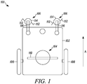
- FIG. 1 is a schematic view of a self-propelled robotic lawnmower 100, according to an example embodiment of the present invention.
- the robotic lawnmower 100 may be powered by a main power source (not shown in the figures), for example but not limited to, an electric motor which may be driven by one or more rechargeable batteries, a pneumatic or hydraulic drive, a fuel cell etc.
- the rechargeable batteries may be charged by electrical energy using a charger, solar energy via a solar panel, or a combination of both.
- the robotic lawnmower 100 includes a body 102, a main cutting unit 104 and one or more trimming units 106.
- the main cutting unit 104 and the trimming units 106 are carried by the body 102.
- the body 102 may be of a monolithic or a multi-part articulating configuration and covered by a housing (not shown).
- the trimming units 106 are mounted substantially towards a front portion of the robotic lawnmower 100 with respect to a direction of travel A.
- the trimming units 106 may be mounted towards a sideway or a rear portion of the robotic lawnmower 100.
- the robotic lawnmower 100 may include a collector (not shown in the figures) which is used to collect the cut vegetation/grass.
- the robotic lawnmower 100 may also include a handle (not shown in the figures) to aid in manual lifting of the robotic lawnmower 100 in a non-operational state.
- the robotic lawnmower 100 may also include a control device (not shown in the figures) which may have a processor, a memory (e.g., ROM, RAM, flash memory etc.) etc. The control device may manoeuvre the robotic lawnmower 100 within the limited area such that the lawnmower performs cutting in an autonomous manner without any supervision. As shown in FIG.
- the robotic lawnmower 100 may be driven by two drive wheels 108 and one or more following wheels (e.g. a caster wheel, not shown). As shown in FIG. 1 , the drive wheels 108 are mounted substantially towards a rear portion of the robotic lawnmower. Other configurations of the drive wheels 108 and the one or more following wheels are possible without departing from the essence of the present invention.
- the robotic lawnmower 100 is configured to cut vegetation within a limited area.
- the limited area may be any terrain with vegetation, such as lawns, gardens, yards, golf courses, fields, or the like.
- the limited area may be demarcated by a perimeter wire (not shown).
- the perimeter wire may be fixed above the ground or embedded under the ground and connected to a signal generator energized by a power supply or directly connected to the power supply.
- the perimeter wire may also form loops around areas within the limited area where cutting is not desired, for example but not limiting to, fixed objects like garden sheds, trees, walls, large stones, bushes or shrubs, flower or vegetable patches, elevated fountains etc. Such loops are referred to as perimeter wire islands.
- the robotic lawnmower 100 may be provided with one or more onboard sensors (not shown) to detect an electrical and/or magnetic signal originating from the perimeter wire.
- the one or more onboard sensors may include, for example, but not limited to, current sensors and/or magnetic field sensors.
- the one or more onboard sensors may be mounted in different positions on the robotic lawnmower 100 and are able to sense the distance and/or orientation of the robotic lawnmower 100 with reference to the perimeter wire. With the help of these one or more sensors and the control device, the robotic lawnmower 100 may navigate within the limited area.
- the robotic lawnmower 100 may systematically follow the perimeter wire in order to locate the charger within the limited area.
- one or more collision or proximity detectors e.g. infrared detectors
- the one or more collision or proximity detectors may assure that the robotic lawnmower 100 steer away or stop in anticipation of a collision.
- instead of a perimeter wire localized perimeter co-ordinates of the limited area may be used to navigate the robotic lawnmower 100.
- the perimeter co-ordinates of the limited area may be stored in the memory accessible of the control device of the robotic lawnmower 100 or in a remote location accessible by the control device.
- the robotic lawnmower 100 may use the perimeter co-ordinates in combination with a localised positioning system to navigate within the limited area. It is apparent to a person of ordinarily skill in the art that the robotic lawnmower 100 may be manoeuvred by any other known methods and systems.
- the main cutting unit 104 includes a rotary cutter 110.
- the main cutting unit 104 may include a cylindrical or reel cutter.
- the rotary cutter 110 may be made of metal, plastic, or the like.
- the rotary cutter 110 may also include design modifications and/or attachments to perform various functions, such as, mulching, controlling the trajectory of the cut vegetation, aerating, digging etc.
- the main cutting unit 104 may include a wire or filament cutter instead of a rotary cutter 110.
- the rotary cutter 110 may be connected to a main driving unit (not shown in the figures) such that the main driving unit may rotate the rotary cutter 110 via a transmission means, for example but not limiting to, gears, belt and pulley, linkages, a frictional drive or a combination of these.
- a transmission means for example but not limiting to, gears, belt and pulley, linkages, a frictional drive or a combination of these.
- the rotary cutter 110 may be vertically adjustable such that it can be lowered or raised in order to vary a depth of cut.
- each of the trimming units 106 may include at least one cutting means 112, a cutting means carrier 114 and a supporting member 116.
- the at least one cutting means 112 may be a wire member, a cutter blade or a reciprocal cutter.
- the cutting means 112 may be made of metal, plastics, or the like.
- the cutting means carrier 114 may be connected to the supporting member 116 by a fixed joint or a movable joint. In an embodiment of the present invention, the movable joint between the cutting means carrier 114 and the supporting member 116 enables the cutting means carrier 114 to move in various orientations with respect to the supporting member 116.
- the supporting member 116 may be attached to the body 102 by a fixed or a movable connection, for example but not limiting to, a pivoting joint, a universal joint, a prismatic joint, a cylindrical joint etc.
- the trimming units 106 may be coupled to the main driving unit.
- the trimming units 106 may be coupled to an auxiliary driving unit (not shown).
- the auxiliary driving unit may be directly driven by the main power source of the robotic lawnmower 100.
- the trimming units 106 are arranged to change between a passive state and an active state. In the passive state, the trimming units 106 may not perform any cutting, whereas in the active state the trimming units 106 may perform cutting.
- the cutting means 112 of the trimming units 106 may be driven by the main driving unit or the auxiliary driving unit, and are arranged to perform cutting adjacent to the body 102 of the robotic lawnmower 100.
- the trimming units 106 when the robotic lawnmower 100 senses the perimeter wire or the perimeter wire islands, the trimming units 106 may change to the active state. This may allow the trimming units 106 to perform edge cutting in the proximity of the perimeter wire or the perimeter wire islands within the limited area.
- the robotic lawnmower 100 may follow the perimeter wire to the charger, and a portion of the perimeter of the limited area is covered by the robotic lawnmower 100.
- the robotic lawnmower 100 may follow the perimeter wire, edge cutting in the proximity of the portion of the perimeter wire is completed. As during the normal operating conditions the robotic lawnmower 100 may repeatedly follow the perimeter wire and effective edge cutting is achieved.
- the trimming units 106 may be arranged to move angularly and/or sideways or vertically. As described above, the supporting members 116 of the trimming units 106 are attached to the body 102 by a movable connection. This assists the angular and/or sideways or vertical movement of the trimming units 106.
- an ancillary driving mechanism may be provided in order to enable the angular and/or sideways or vertical movement of the trimming units 106.
- the ancillary driving mechanism may include a motor assisted mechanism to transmit angular and/or sideways or vertical movement to the trimming units 106.
- the ancillary driving mechanism may be driven by the main driving unit or the auxiliary driving unit. Whenever the trimming units 106 are changed to the active state in response to an external event, such as sensing the perimeter wire and/or sensing the perimeter loop, the ancillary driving mechanism may also be activated. Hence, the angular and/or sideways or vertical movement of the trimming units 106 along with the rotational or reciprocal movement of the cutting means 112 ensures a uniform edge cutting.
- the robotic lawnmower 100 is arranged to travel in a random pattern within the limited area.
- the robotic lawnmower 100 may randomly change the direction of movement in response to an external event.
- the external event may include a collision with an obstacle (e.g. sheds, trees, fountain, and stones), sharp turns at corners in addition to sensing the perimeter wire and/or the perimeter loop.
- the trimming units 106 may change from the passive state to the active state in response to the external event.
- the robotic lawnmower 100 moving randomly within the limited area may provide edge cutting around the obstacles, sharp turn corners and the perimeter islands.
- a deactivating event may change the trimming unit 106 from the active state to the passive state.
- the deactivating event may include collision free systematic movement of the robotic lawnmower 100, absence of the obstacle/corners, a substantial distance from the perimeter wire etc.
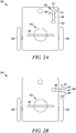
- FIG. 2A is a schematic view of a robotic lawnmower 100, according to another embodiment of the present invention.
- the trimming unit 106 is partially disposed within the housing of the robotic lawnmower 100 and the trimming unit 106 is in the passive state. While disposed within the housing the trimming unit 106 is in a position which is hereinafter referred to as a passive position. In the passive position the trimming unit 106 may avoid bushes, branches and other random objects, such that any damage to the trimming unit 106 is prevented. Further, in the passive position the trimming unit 106 may increase the manoeuvrability of the robotic lawnmower 100.
- the trimming unit 106 may stay in the passive position, and in case of the external event, for example, sensing the perimeter wire and/or perimeter wire island, switch to an active position. Iin FIG. 2B , the trimming unit 106 is in the active position, i.e. partially outside the housing of the robotic lawnmower 100. In the active position the trimming unit 106 may change from the passive state to the active state and perform edge cutting.
- the movable joint between the supporting member 116 and the body 102 may have an auxiliary mechanism, for example a motor assisted and/or spring biased lever or bar member to move the trimming unit 106 from the passive position to the active position.
- the supporting member 116 may be flexibly mounted to the body 102 by means of a spring member.
- the trimming unit 106 may slide along the fixed objects in the limited area, for examples bushes, fountains and large stones.
- the supporting member 116 may be flexibly mounted to the body 102 by means of a spring member in addition to the auxiliary mechanism. While in the active position, the trimming unit may perform edge cutting and may also be flexible enough to slide along the fixed objects in order to avoid any hindrance and/or damage.
- the robotic lawnmower 100 may be arranged to travel in the random pattern while the trimming unit 106 is in the active position.
- the trimming unit 106 as described above is capable of performing the complete edge cutting. It is apparent to a person skilled in the art that the robotic lawnmower 100 may have one or more trimming units 106 positioned on any portion of the robotic lawnmower 100.
- the control device of the robotic lawnmower 100 may have stored a computer program to optimize the edge cutting and the normal cutting, based on the shape and size of the limited area.
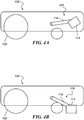
- FIGS. 4A and 4B are schematic views of a robotic lawnmower 100, according to another embodiment of the present invention.
- the trimming unit 106 is arranged to be move vertically between a raised passive position and a lowered, active position.
- the trimming unit 106 is disposed in a raised position within the housing of the robotic lawnmower 100, and the trimming unit 106 is in the passive state.
- the trimming unit 106 In the passive position the trimming unit 106 is raised within the housing such that any damage to the trimming unit 106 is prevented.
- the trimming unit 106 may stay in the passive position, and in case of the external event, for example, sensing the perimeter wire and/or perimeter wire island, switch to an active position.
- the trimming unit 106 is in the lowered active position. In the active position the trimming unit 106 may change from the passive state to the active state and perform edge cutting.
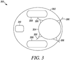
- FIG. 3 is a schematic view of a self-propelled robotic lawnmower 300, according to yet another example embodiment of the present invention.
- the robotic lawnmower 300 includes a body 302, a main cutting unit 304 and trimming units 306.
- the trimming units 306 may be wire members carried by the main cutting unit 304.
- the trimming units 306 are arranged to perform edge cutting in an area adjacent to the robotic lawnmower 300.
- the robotic lawnmower 300 may be driven by two drive wheels 308 and a tail wheel 310 (e.g. a caster wheel). Other configurations of the drive wheels 308 and the tail wheel 310 are possible without departing from the essence of the present invention.
- the trimming units 306 may be wire members made of metal, plastic, or the like.
- the robotic lawnmower 300 is configured to cut the vegetation within the limited area such that the trimming units 306 may be used for edge cutting. Further, the robotic lawnmower 300 may be arranged to move in a random pattern within the limited area.
- the robotic lawnmower 300 may be battery powered, using electrical energy or solar energy via a solar panel, or a combination of both. Further, any known methods and systems may be used for the navigation of the robotic lawnmower 300, for example using the perimeter wire or the local positioning system.
Landscapes
- Life Sciences & Earth Sciences (AREA)
- Environmental Sciences (AREA)
- Harvester Elements (AREA)
- Guiding Agricultural Machines (AREA)
- Control Of Position, Course, Altitude, Or Attitude Of Moving Bodies (AREA)
Claims (23)
- Tondeuse à gazon robotisée automotrice (100) qui est configurée pour couper une végétation dans une zone limitée pendant un fonctionnement normal, la tondeuse à gazon comprenant :un corps (102) recouvert d'un boîtier ;une unité de coupe principale (104) portée par le corps ;au moins une unité de taille (106) portée par le corps ou le boîtier,caractérisée en ce que l'au moins une unité de coupe (106) est agencée de manière à changer automatiquement entre un état passif pendant un fonctionnement normal, dans lequel l'unité de taille est passive et n'est donc pas agencée pour effectuer une coupe quelconque, et un état actif, dans lequel l'unité de taille est active et ainsi agencée pour effectuer une coupe.
- Tondeuse à gazon robotisée automotrice selon la revendication 1, dans laquelle l'au moins une unité de taille est agencée de manière à être automatiquement mobile entre une position passive et une position active, dans laquelle l'au moins une unité de taille est à l'état passif lorsqu'elle est dans la position passive, et dans laquelle l'au moins une unité de taille est à l'état actif lorsqu'elle est dans la position active.
- Tondeuse à gazon robotisée automotrice selon la revendication 2, dans laquelle dans la position passive l'au moins une unité de taille est disposée au moins partiellement à l'intérieur du boîtier.
- Tondeuse à gazon robotisée automotrice selon la revendication 2, dans laquelle dans la position active l'au moins une unité de taille est étendue au moins partiellement à l'extérieur du boîtier.
- Tondeuse à gazon robotisée automotrice selon la revendication 1, dans laquelle à l'état actif l'au moins une unité de taille est agencée pour se déplacer angulairement.
- Tondeuse à gazon robotisée automotrice selon la revendication 1, dans laquelle à l'état actif l'au moins une unité de taille est agencée pour se déplacer latéralement.
- Tondeuse à gazon robotisée automotrice selon la revendication 1, dans laquelle à l'état actif l'au moins une unité de taille est agencée pour se déplacer verticalement.
- Tondeuse à gazon robotisée automotrice selon la revendication 1, dans laquelle la tondeuse à gazon est agencée pour se déplacer selon un motif aléatoire dans la zone limitée.
- Tondeuse à gazon robotisée automotrice selon la revendication 2, dans laquelle l'au moins une unité de taille est sélectivement dans la position active pendant que la tondeuse à gazon se déplace selon un motif aléatoire.
- Tondeuse à gazon robotisée automotrice selon la revendication 1, dans laquelle la tondeuse à gazon est agencée pour détecter un fil de périmètre, et en réponse à cela, met les unités de taille (106) à l'état actif.
- Tondeuse à gazon robotisée automotrice selon la revendication 9, dans laquelle l'unité de taille est portée par l'unité de coupe principale.
- Tondeuse à gazon robotisée automotrice selon la revendication 9, dans laquelle l'unité de taille est portée par le corps.
- Tondeuse à gazon robotisée automotrice selon la revendication 9, dans laquelle l'unité de taille est portée par le boîtier.
- Tondeuse à gazon robotisée automotrice selon les revendications 1 à 11, dans laquelle l'au moins une unité de taille est couplée à une unité d'entraînement principale.
- Tondeuse à gazon robotisée automotrice selon les revendications 1 à 11, dans laquelle l'au moins une unité de taille est couplée à une unité d'entraînement auxiliaire.
- Tondeuse à gazon robotisée automotrice selon les revendications 1 à 11, dans laquelle l'au moins une unité de taille comprend au moins un élément de fil.
- Tondeuse à gazon robotisée automotrice selon les revendications 1 à 11, dans laquelle l'au moins une unité de taille comprend au moins une lame de coupe.
- Tondeuse à gazon robotisée automotrice selon les revendications 1 à 11, dans laquelle l'au moins une unité de taille comprend au moins un dispositif de coupe à mouvement alternatif.
- Procédé de commande d'une tondeuse robotisée automotrice qui est configurée pour couper une végétation dans une zone limitée pendant un fonctionnement normal, la tondeuse à gazon robotisée comprenant une unité de coupe principale et au moins une unité de taille, le procédé comprenant les étapes consistant :à tondre par l'intermédiaire de la tondeuse à gazon selon une ligne sensiblement droite à travers la zone limitée ;en réponse à un événement externe :à changer aléatoirement une direction de déplacement de la tondeuse à gazon ; età activer l'au moins une unité de taille.
- Procédé de commande d'une tondeuse à gazon robotisée automotrice selon la revendication 19, dans lequel l'étape d'activation de l'au moins une unité de taille comprend le fait de faire passer l'au moins une unité d'entraînement d'un état passif et à un état actif.
- Procédé de commande d'une tondeuse à gazon robotisée automotrice selon la revendication 19, comprenant en outre l'étape consistant :à désactiver l'au moins une unité de taille en réponse à un événement de désactivation.
- Procédé de commande d'une tondeuse à gazon robotisée automotrice selon la revendication 21, dans lequel l'étape de désactivation de l'au moins un dispositif de taille comprend le fait de faire passe l'au moins une unité de taille d'un état actif et à un état passif.
- Procédé de commande d'une tondeuse à gazon robotisée automotrice selon les revendications 19 à 22, dans lequel l'au moins une unité de taille est dans une position d'état passif, lorsqu'elle est à l'état passif, et dans lequel l'au moins une unité de taille est dans une position active lorsqu'elle est à l'état actif, et dans lequel les étapes d'activation et de désactivation de l'au moins une unité de taille comprennent l'étape consistant à déplacer l'au moins une unité de taille de la position active à la position passive et, de manière correspondante, de la position passive à la position active.
Applications Claiming Priority (1)
| Application Number | Priority Date | Filing Date | Title |
|---|---|---|---|
| PCT/SE2010/050300 WO2011115536A1 (fr) | 2010-03-18 | 2010-03-18 | Tondeuse à gazon robotisée pourvue de parties tranchantes |
Publications (3)
| Publication Number | Publication Date |
|---|---|
| EP2547193A1 EP2547193A1 (fr) | 2013-01-23 |
| EP2547193A4 EP2547193A4 (fr) | 2013-11-27 |
| EP2547193B1 true EP2547193B1 (fr) | 2017-03-01 |
Family
ID=44649448
Family Applications (1)
| Application Number | Title | Priority Date | Filing Date |
|---|---|---|---|
| EP10848076.5A Active EP2547193B1 (fr) | 2010-03-18 | 2010-03-18 | Tondeuse à gazon robotisée pourvue de parties tranchantes |
Country Status (2)
| Country | Link |
|---|---|
| EP (1) | EP2547193B1 (fr) |
| WO (1) | WO2011115536A1 (fr) |
Cited By (4)
| Publication number | Priority date | Publication date | Assignee | Title |
|---|---|---|---|---|
| WO2019228461A1 (fr) | 2018-05-30 | 2019-12-05 | 苏州宝时得电动工具有限公司 | Tondeuse à gazon automatique et son procédé de commande |
| US11864495B2 (en) | 2020-03-16 | 2024-01-09 | Samsung Electronics Co., Ltd. | Robot lawnmower |
| US11991955B2 (en) | 2018-05-25 | 2024-05-28 | The Toro Company | Systems and methods for operating a robotic machine in an autonomous mode and a manual mode |
| EP3858128B1 (fr) * | 2018-09-27 | 2024-09-04 | Positec Power Tools (Suzhou) Co., Ltd | Tondeuse automatique, procédé et appareil pour la faire fonctionner et la commander, et dispositif électronique |
Families Citing this family (18)
| Publication number | Priority date | Publication date | Assignee | Title |
|---|---|---|---|---|
| WO2014101840A1 (fr) | 2012-12-28 | 2014-07-03 | 苏州宝时得电动工具有限公司 | Système de tondeuse automatique |
| EP2972627B1 (fr) | 2013-03-15 | 2019-05-08 | MTD Products Inc | Système de travail mobile autonome comprenant une station de base à réflectivité variable |
| CN104704980A (zh) * | 2013-12-12 | 2015-06-17 | 苏州宝时得电动工具有限公司 | 一种自动割草机 |
| EP3102021B1 (fr) * | 2014-02-03 | 2020-03-11 | Husqvarna AB | Ressort de plaque conçu pour maintenir un outil, outil, support d'outil, outil de travail robotique et système d'outil de travail robotique |
| CA3023107A1 (fr) | 2016-05-06 | 2017-11-09 | Mtd Products Inc | Systeme et procede de navigation de tondeuse autonome |
| US11172608B2 (en) | 2016-06-30 | 2021-11-16 | Tti (Macao Commercial Offshore) Limited | Autonomous lawn mower and a system for navigating thereof |
| CN109416543B (zh) * | 2016-06-30 | 2022-11-08 | 创科(澳门离岸商业服务)有限公司 | 一种自主式割草机及其导航系统 |
| AU2017367062A1 (en) * | 2016-11-29 | 2019-07-18 | Briggs & Stratton, Llc | Robotic lawn mower including removable rechargeable battery module |
| EP3412129B1 (fr) | 2017-06-09 | 2020-08-19 | Andreas Stihl AG & Co. KG | Robot de traitement d'espaces verts mobile, autonome |
| EP3412128B1 (fr) | 2017-06-09 | 2021-05-12 | Andreas Stihl AG & Co. KG | Système de traitement d'espaces verts et procédé de détection d'au moins une partie d'un bord périphérique d'une surface à traiter |
| EP3850936A4 (fr) | 2018-09-12 | 2022-08-03 | Positec Power Tools (Suzhou) Co., Ltd | Dispositif automoteur et son système de fonctionnement automatique |
| IT201800009580A1 (it) * | 2018-10-18 | 2020-04-18 | Mdb Srl Con Socio Unico | Tagliaerba radiocomandato |
| DE102019103335A1 (de) * | 2019-02-11 | 2020-08-13 | Brüggli | Vorrichtung, vorzugsweise autonome Robotervorrichtung, zum Mähen von Gras |
| CN112438109B (zh) * | 2019-08-27 | 2022-07-12 | 苏州宝时得电动工具有限公司 | 自动割草机 |
| CN112690081B (zh) * | 2019-10-23 | 2023-06-06 | 苏州宝时得电动工具有限公司 | 自动割草机 |
| JP2023513539A (ja) * | 2020-02-07 | 2023-03-31 | テクサロバ・テクノロジー・インコーポレイテッド | 従来にないカッターのロボット芝刈り機 |
| US10947685B1 (en) | 2020-09-10 | 2021-03-16 | Jay Hirshberg | Object-gathering apparatus |
| CN115777327A (zh) * | 2022-11-30 | 2023-03-14 | 深圳华芯信息技术股份有限公司 | 一种割草机器人 |
Family Cites Families (7)
| Publication number | Priority date | Publication date | Assignee | Title |
|---|---|---|---|---|
| US3550714A (en) * | 1964-10-20 | 1970-12-29 | Mowbot Inc | Lawn mower |
| US3698523A (en) * | 1969-10-20 | 1972-10-17 | Mowbot Inc | Self-propelled random motion lawnmower |
| US5572856A (en) * | 1994-02-18 | 1996-11-12 | Ku; Chingyu J. | Remotely controlled lawn mower |
| US6701700B2 (en) * | 2000-07-10 | 2004-03-09 | Stephen Timothy Keane | Lawnmower-attached edge trimmer apparatus |
| US7677344B2 (en) * | 2003-08-05 | 2010-03-16 | Medina Luis M | Hybrid remote control lawn mower |
| IT1363355B1 (it) * | 2005-07-22 | 2009-07-03 | Fabrizio Bernini | Tosaerba automatico |
| EP3067771B1 (fr) * | 2006-03-17 | 2017-11-08 | iRobot Corporation | Confinement de robot |
-
2010
- 2010-03-18 EP EP10848076.5A patent/EP2547193B1/fr active Active
- 2010-03-18 WO PCT/SE2010/050300 patent/WO2011115536A1/fr active Application Filing
Non-Patent Citations (1)
| Title |
|---|
| None * |
Cited By (6)
| Publication number | Priority date | Publication date | Assignee | Title |
|---|---|---|---|---|
| US11991955B2 (en) | 2018-05-25 | 2024-05-28 | The Toro Company | Systems and methods for operating a robotic machine in an autonomous mode and a manual mode |
| WO2019228461A1 (fr) | 2018-05-30 | 2019-12-05 | 苏州宝时得电动工具有限公司 | Tondeuse à gazon automatique et son procédé de commande |
| EP3804496A4 (fr) * | 2018-05-30 | 2022-03-02 | Positec Power Tools (Suzhou) Co., Ltd | Tondeuse à gazon automatique et son procédé de commande |
| US12082524B2 (en) | 2018-05-30 | 2024-09-10 | Positec Power Tools (Suzhou) Co, Ltd. | Autonomous lawn mower with edger and control method thereof |
| EP3858128B1 (fr) * | 2018-09-27 | 2024-09-04 | Positec Power Tools (Suzhou) Co., Ltd | Tondeuse automatique, procédé et appareil pour la faire fonctionner et la commander, et dispositif électronique |
| US11864495B2 (en) | 2020-03-16 | 2024-01-09 | Samsung Electronics Co., Ltd. | Robot lawnmower |
Also Published As
| Publication number | Publication date |
|---|---|
| EP2547193A4 (fr) | 2013-11-27 |
| EP2547193A1 (fr) | 2013-01-23 |
| WO2011115536A1 (fr) | 2011-09-22 |
Similar Documents
| Publication | Publication Date | Title |
|---|---|---|
| EP2547193B1 (fr) | Tondeuse à gazon robotisée pourvue de parties tranchantes | |
| US12082524B2 (en) | Autonomous lawn mower with edger and control method thereof | |
| CN112367830B (zh) | 用于在自动和手动模式下操作机器人机器的系统和方法 | |
| AU2018306123B2 (en) | Electric powered disc mower | |
| WO2023221430A1 (fr) | Robot de désherbage sans pilote s'adaptant au terrain pour verger dans une région montagneuse | |
| CN111133882B (zh) | 一种具有全向割草刀盘的割草机 | |
| CA3039189A1 (fr) | Accessoire de tonte rotatif de coupe-bordure | |
| US20220176544A1 (en) | Robotic Farm System and Method of Operation | |
| CN111903313A (zh) | 一种智能割草机及其控制方法 | |
| CN114424703A (zh) | 一种新能源割草机器人 | |
| DE112022001682T5 (de) | Mähroboter | |
| WO2000074465A1 (fr) | Machine de tonte automatisee | |
| CN113573574A (zh) | 用于割草的设备、优选自主机器人设备 | |
| CN216960804U (zh) | 一种新能源割草机器人 | |
| WO2023121527A1 (fr) | Tondeuse à gazon robotisée ayant des propriétés de coupe améliorées | |
| CN110547088A (zh) | 割草机及其系统和操作方法 | |
| US20190069481A1 (en) | Attachment plate for supporting walk behind trimmers with third wheel | |
| CN111296053A (zh) | 一种果园自动避障除草机 | |
| CN219248590U (zh) | 一种割草机器人 | |
| RU2773946C2 (ru) | Электроприводная дисковая косилка | |
| CN213662488U (zh) | 智能割草机 | |
| US20220174871A1 (en) | Turf Trimming System and Integrated Control System | |
| CA3151043A1 (fr) | Systeme de tonte de pelouse et systeme de commande integre |
Legal Events
| Date | Code | Title | Description |
|---|---|---|---|
| PUAI | Public reference made under article 153(3) epc to a published international application that has entered the european phase |
Free format text: ORIGINAL CODE: 0009012 |
|
| 17P | Request for examination filed |
Effective date: 20121003 |
|
| AK | Designated contracting states |
Kind code of ref document: A1 Designated state(s): AT BE BG CH CY CZ DE DK EE ES FI FR GB GR HR HU IE IS IT LI LT LU LV MC MK MT NL NO PL PT RO SE SI SK SM TR |
|
| DAX | Request for extension of the european patent (deleted) | ||
| A4 | Supplementary search report drawn up and despatched |
Effective date: 20131030 |
|
| RIC1 | Information provided on ipc code assigned before grant |
Ipc: A01D 34/00 20060101ALI20131024BHEP Ipc: A01D 34/84 20060101AFI20131024BHEP Ipc: A01D 43/16 20060101ALI20131024BHEP |
|
| GRAP | Despatch of communication of intention to grant a patent |
Free format text: ORIGINAL CODE: EPIDOSNIGR1 |
|
| INTG | Intention to grant announced |
Effective date: 20161004 |
|
| RIN1 | Information on inventor provided before grant (corrected) |
Inventor name: AHLIN, PETER Inventor name: GUSTAVSSON, CHRISTER Inventor name: JAEGENSTEDT, PATRIK Inventor name: VAN DE GRIENDT, ANTOINE Inventor name: HALLIN, PETER Inventor name: ELONSSON, MARTIN |
|
| GRAS | Grant fee paid |
Free format text: ORIGINAL CODE: EPIDOSNIGR3 |
|
| GRAA | (expected) grant |
Free format text: ORIGINAL CODE: 0009210 |
|
| AK | Designated contracting states |
Kind code of ref document: B1 Designated state(s): AT BE BG CH CY CZ DE DK EE ES FI FR GB GR HR HU IE IS IT LI LT LU LV MC MK MT NL NO PL PT RO SE SI SK SM TR |
|
| REG | Reference to a national code |
Ref country code: GB Ref legal event code: FG4D |
|
| REG | Reference to a national code |
Ref country code: CH Ref legal event code: EP Ref country code: AT Ref legal event code: REF Ref document number: 870192 Country of ref document: AT Kind code of ref document: T Effective date: 20170315 |
|
| REG | Reference to a national code |
Ref country code: IE Ref legal event code: FG4D |
|
| REG | Reference to a national code |
Ref country code: FR Ref legal event code: PLFP Year of fee payment: 8 |
|
| REG | Reference to a national code |
Ref country code: DE Ref legal event code: R096 Ref document number: 602010040483 Country of ref document: DE |
|
| REG | Reference to a national code |
Ref country code: SE Ref legal event code: TRGR |
|
| REG | Reference to a national code |
Ref country code: NL Ref legal event code: MP Effective date: 20170301 |
|
| REG | Reference to a national code |
Ref country code: LT Ref legal event code: MG4D |
|
| REG | Reference to a national code |
Ref country code: AT Ref legal event code: MK05 Ref document number: 870192 Country of ref document: AT Kind code of ref document: T Effective date: 20170301 |
|
| PG25 | Lapsed in a contracting state [announced via postgrant information from national office to epo] |
Ref country code: HR Free format text: LAPSE BECAUSE OF FAILURE TO SUBMIT A TRANSLATION OF THE DESCRIPTION OR TO PAY THE FEE WITHIN THE PRESCRIBED TIME-LIMIT Effective date: 20170301 Ref country code: NO Free format text: LAPSE BECAUSE OF FAILURE TO SUBMIT A TRANSLATION OF THE DESCRIPTION OR TO PAY THE FEE WITHIN THE PRESCRIBED TIME-LIMIT Effective date: 20170601 Ref country code: LT Free format text: LAPSE BECAUSE OF FAILURE TO SUBMIT A TRANSLATION OF THE DESCRIPTION OR TO PAY THE FEE WITHIN THE PRESCRIBED TIME-LIMIT Effective date: 20170301 Ref country code: GR Free format text: LAPSE BECAUSE OF FAILURE TO SUBMIT A TRANSLATION OF THE DESCRIPTION OR TO PAY THE FEE WITHIN THE PRESCRIBED TIME-LIMIT Effective date: 20170602 Ref country code: FI Free format text: LAPSE BECAUSE OF FAILURE TO SUBMIT A TRANSLATION OF THE DESCRIPTION OR TO PAY THE FEE WITHIN THE PRESCRIBED TIME-LIMIT Effective date: 20170301 |
|
| PG25 | Lapsed in a contracting state [announced via postgrant information from national office to epo] |
Ref country code: LV Free format text: LAPSE BECAUSE OF FAILURE TO SUBMIT A TRANSLATION OF THE DESCRIPTION OR TO PAY THE FEE WITHIN THE PRESCRIBED TIME-LIMIT Effective date: 20170301 Ref country code: AT Free format text: LAPSE BECAUSE OF FAILURE TO SUBMIT A TRANSLATION OF THE DESCRIPTION OR TO PAY THE FEE WITHIN THE PRESCRIBED TIME-LIMIT Effective date: 20170301 Ref country code: BG Free format text: LAPSE BECAUSE OF FAILURE TO SUBMIT A TRANSLATION OF THE DESCRIPTION OR TO PAY THE FEE WITHIN THE PRESCRIBED TIME-LIMIT Effective date: 20170601 Ref country code: ES Free format text: LAPSE BECAUSE OF FAILURE TO SUBMIT A TRANSLATION OF THE DESCRIPTION OR TO PAY THE FEE WITHIN THE PRESCRIBED TIME-LIMIT Effective date: 20170301 |
|
| PG25 | Lapsed in a contracting state [announced via postgrant information from national office to epo] |
Ref country code: NL Free format text: LAPSE BECAUSE OF FAILURE TO SUBMIT A TRANSLATION OF THE DESCRIPTION OR TO PAY THE FEE WITHIN THE PRESCRIBED TIME-LIMIT Effective date: 20170301 |
|
| PG25 | Lapsed in a contracting state [announced via postgrant information from national office to epo] |
Ref country code: IT Free format text: LAPSE BECAUSE OF FAILURE TO SUBMIT A TRANSLATION OF THE DESCRIPTION OR TO PAY THE FEE WITHIN THE PRESCRIBED TIME-LIMIT Effective date: 20170301 Ref country code: RO Free format text: LAPSE BECAUSE OF FAILURE TO SUBMIT A TRANSLATION OF THE DESCRIPTION OR TO PAY THE FEE WITHIN THE PRESCRIBED TIME-LIMIT Effective date: 20170301 Ref country code: EE Free format text: LAPSE BECAUSE OF FAILURE TO SUBMIT A TRANSLATION OF THE DESCRIPTION OR TO PAY THE FEE WITHIN THE PRESCRIBED TIME-LIMIT Effective date: 20170301 Ref country code: CZ Free format text: LAPSE BECAUSE OF FAILURE TO SUBMIT A TRANSLATION OF THE DESCRIPTION OR TO PAY THE FEE WITHIN THE PRESCRIBED TIME-LIMIT Effective date: 20170301 Ref country code: SK Free format text: LAPSE BECAUSE OF FAILURE TO SUBMIT A TRANSLATION OF THE DESCRIPTION OR TO PAY THE FEE WITHIN THE PRESCRIBED TIME-LIMIT Effective date: 20170301 |
|
| REG | Reference to a national code |
Ref country code: CH Ref legal event code: PL |
|
| PG25 | Lapsed in a contracting state [announced via postgrant information from national office to epo] |
Ref country code: IS Free format text: LAPSE BECAUSE OF FAILURE TO SUBMIT A TRANSLATION OF THE DESCRIPTION OR TO PAY THE FEE WITHIN THE PRESCRIBED TIME-LIMIT Effective date: 20170701 Ref country code: SM Free format text: LAPSE BECAUSE OF FAILURE TO SUBMIT A TRANSLATION OF THE DESCRIPTION OR TO PAY THE FEE WITHIN THE PRESCRIBED TIME-LIMIT Effective date: 20170301 Ref country code: PT Free format text: LAPSE BECAUSE OF FAILURE TO SUBMIT A TRANSLATION OF THE DESCRIPTION OR TO PAY THE FEE WITHIN THE PRESCRIBED TIME-LIMIT Effective date: 20170703 Ref country code: PL Free format text: LAPSE BECAUSE OF FAILURE TO SUBMIT A TRANSLATION OF THE DESCRIPTION OR TO PAY THE FEE WITHIN THE PRESCRIBED TIME-LIMIT Effective date: 20170301 |
|
| REG | Reference to a national code |
Ref country code: DE Ref legal event code: R097 Ref document number: 602010040483 Country of ref document: DE |
|
| REG | Reference to a national code |
Ref country code: IE Ref legal event code: MM4A |
|
| PLBE | No opposition filed within time limit |
Free format text: ORIGINAL CODE: 0009261 |
|
| STAA | Information on the status of an ep patent application or granted ep patent |
Free format text: STATUS: NO OPPOSITION FILED WITHIN TIME LIMIT |
|
| PG25 | Lapsed in a contracting state [announced via postgrant information from national office to epo] |
Ref country code: MC Free format text: LAPSE BECAUSE OF FAILURE TO SUBMIT A TRANSLATION OF THE DESCRIPTION OR TO PAY THE FEE WITHIN THE PRESCRIBED TIME-LIMIT Effective date: 20170301 Ref country code: LU Free format text: LAPSE BECAUSE OF NON-PAYMENT OF DUE FEES Effective date: 20170318 Ref country code: DK Free format text: LAPSE BECAUSE OF FAILURE TO SUBMIT A TRANSLATION OF THE DESCRIPTION OR TO PAY THE FEE WITHIN THE PRESCRIBED TIME-LIMIT Effective date: 20170301 |
|
| 26N | No opposition filed |
Effective date: 20171204 |
|
| GBPC | Gb: european patent ceased through non-payment of renewal fee |
Effective date: 20170601 |
|
| PG25 | Lapsed in a contracting state [announced via postgrant information from national office to epo] |
Ref country code: CH Free format text: LAPSE BECAUSE OF NON-PAYMENT OF DUE FEES Effective date: 20170331 Ref country code: SI Free format text: LAPSE BECAUSE OF FAILURE TO SUBMIT A TRANSLATION OF THE DESCRIPTION OR TO PAY THE FEE WITHIN THE PRESCRIBED TIME-LIMIT Effective date: 20170301 Ref country code: LI Free format text: LAPSE BECAUSE OF NON-PAYMENT OF DUE FEES Effective date: 20170331 Ref country code: IE Free format text: LAPSE BECAUSE OF NON-PAYMENT OF DUE FEES Effective date: 20170318 |
|
| REG | Reference to a national code |
Ref country code: FR Ref legal event code: PLFP Year of fee payment: 9 |
|
| REG | Reference to a national code |
Ref country code: BE Ref legal event code: MM Effective date: 20170331 |
|
| PG25 | Lapsed in a contracting state [announced via postgrant information from national office to epo] |
Ref country code: GB Free format text: LAPSE BECAUSE OF NON-PAYMENT OF DUE FEES Effective date: 20170601 |
|
| PG25 | Lapsed in a contracting state [announced via postgrant information from national office to epo] |
Ref country code: BE Free format text: LAPSE BECAUSE OF NON-PAYMENT OF DUE FEES Effective date: 20170331 |
|
| PG25 | Lapsed in a contracting state [announced via postgrant information from national office to epo] |
Ref country code: MT Free format text: LAPSE BECAUSE OF NON-PAYMENT OF DUE FEES Effective date: 20170318 |
|
| PG25 | Lapsed in a contracting state [announced via postgrant information from national office to epo] |
Ref country code: HU Free format text: LAPSE BECAUSE OF FAILURE TO SUBMIT A TRANSLATION OF THE DESCRIPTION OR TO PAY THE FEE WITHIN THE PRESCRIBED TIME-LIMIT; INVALID AB INITIO Effective date: 20100318 |
|
| PG25 | Lapsed in a contracting state [announced via postgrant information from national office to epo] |
Ref country code: CY Free format text: LAPSE BECAUSE OF NON-PAYMENT OF DUE FEES Effective date: 20170301 |
|
| PG25 | Lapsed in a contracting state [announced via postgrant information from national office to epo] |
Ref country code: MK Free format text: LAPSE BECAUSE OF FAILURE TO SUBMIT A TRANSLATION OF THE DESCRIPTION OR TO PAY THE FEE WITHIN THE PRESCRIBED TIME-LIMIT Effective date: 20170301 |
|
| PG25 | Lapsed in a contracting state [announced via postgrant information from national office to epo] |
Ref country code: TR Free format text: LAPSE BECAUSE OF FAILURE TO SUBMIT A TRANSLATION OF THE DESCRIPTION OR TO PAY THE FEE WITHIN THE PRESCRIBED TIME-LIMIT Effective date: 20170301 |
|
| P01 | Opt-out of the competence of the unified patent court (upc) registered |
Effective date: 20230419 |
|
| PGFP | Annual fee paid to national office [announced via postgrant information from national office to epo] |
Ref country code: DE Payment date: 20240209 Year of fee payment: 15 |
|
| PGFP | Annual fee paid to national office [announced via postgrant information from national office to epo] |
Ref country code: SE Payment date: 20240206 Year of fee payment: 15 Ref country code: FR Payment date: 20240206 Year of fee payment: 15 |