EP2546958A1 - Electric motor rotor, electric motor, air conditioner, and production method for electric motor rotor - Google Patents
Electric motor rotor, electric motor, air conditioner, and production method for electric motor rotor Download PDFInfo
- Publication number
- EP2546958A1 EP2546958A1 EP10847417A EP10847417A EP2546958A1 EP 2546958 A1 EP2546958 A1 EP 2546958A1 EP 10847417 A EP10847417 A EP 10847417A EP 10847417 A EP10847417 A EP 10847417A EP 2546958 A1 EP2546958 A1 EP 2546958A1
- Authority
- EP
- European Patent Office
- Prior art keywords
- section
- shaft
- electric motor
- resin
- roller bearing
- Prior art date
- Legal status (The legal status is an assumption and is not a legal conclusion. Google has not performed a legal analysis and makes no representation as to the accuracy of the status listed.)
- Granted
Links
Images






Classifications
-
- H—ELECTRICITY
- H02—GENERATION; CONVERSION OR DISTRIBUTION OF ELECTRIC POWER
- H02K—DYNAMO-ELECTRIC MACHINES
- H02K11/00—Structural association of dynamo-electric machines with electric components or with devices for shielding, monitoring or protection
- H02K11/20—Structural association of dynamo-electric machines with electric components or with devices for shielding, monitoring or protection for measuring, monitoring, testing, protecting or switching
- H02K11/21—Devices for sensing speed or position, or actuated thereby
- H02K11/215—Magnetic effect devices, e.g. Hall-effect or magneto-resistive elements
-
- H—ELECTRICITY
- H02—GENERATION; CONVERSION OR DISTRIBUTION OF ELECTRIC POWER
- H02K—DYNAMO-ELECTRIC MACHINES
- H02K1/00—Details of the magnetic circuit
- H02K1/06—Details of the magnetic circuit characterised by the shape, form or construction
- H02K1/22—Rotating parts of the magnetic circuit
- H02K1/27—Rotor cores with permanent magnets
- H02K1/2706—Inner rotors
- H02K1/272—Inner rotors the magnetisation axis of the magnets being perpendicular to the rotor axis
- H02K1/2726—Inner rotors the magnetisation axis of the magnets being perpendicular to the rotor axis the rotor consisting of a single magnet or two or more axially juxtaposed single magnets
- H02K1/2733—Annular magnets
-
- H—ELECTRICITY
- H02—GENERATION; CONVERSION OR DISTRIBUTION OF ELECTRIC POWER
- H02K—DYNAMO-ELECTRIC MACHINES
- H02K5/00—Casings; Enclosures; Supports
- H02K5/04—Casings or enclosures characterised by the shape, form or construction thereof
- H02K5/16—Means for supporting bearings, e.g. insulating supports or means for fitting bearings in the bearing-shields
- H02K5/173—Means for supporting bearings, e.g. insulating supports or means for fitting bearings in the bearing-shields using bearings with rolling contact, e.g. ball bearings
- H02K5/1732—Means for supporting bearings, e.g. insulating supports or means for fitting bearings in the bearing-shields using bearings with rolling contact, e.g. ball bearings radially supporting the rotary shaft at both ends of the rotor
Definitions
- the present invention relates to an electric motor rotor in which a roller bearing is used and relates to an electric motor rotor suitable for an electric motor driven by an inverter. Further, the present invention relates to an electric motor in which the electric motor rotor is used, a method of manufacturing the electric motor rotor, and an air conditioner mounted with the electric motor.
- a carrier frequency of the inverter is set high.
- a shaft voltage generated based on high-frequency induction in a shaft of the electric motor increases and a potential difference present between an inner ring and an outer ring of a roller bearing that supports the shaft increases. Therefore, an electric current easily flows to the roller bearing.
- an electric motor including a stator formed by winding a coil, a frame that fixes the stator, a rotor opposed to the stator via a very small air gap, a shaft fixedly attached with the rotor and rotatably born via the roller bearing, and a bearing bracket that supports the roller bearing via an insulating material is provided, wherein a concave section is provided on a side of the bearing bracket in contact with the insulating material, and a convex section corresponding to the concave section of the bearing bracket is provided in the insulating material, such that the convex section of the insulating material is fit in the concave section of the bearing bracket and fixed (see, for example, Patent Literature 1).
- An electrolytic corrosion preventing roller bearing in which an insulating coating film is formed on an inner ring fitting surface or an outer ring fitting surface of a roller bearing or both of the inner ring fitting surface and the outer ring fitting surface is proposed, wherein a boundary surface between a circumferential surface of the inner ring fitting surface or a circumferential surface of the outer ring fitting surface and a chamfered section assumes a gentle taper surface or an arcuate surface having a large curvature radius, and the electrolytic corrosion preventing roller bearing has, on at least one fitting surface, an insulating coating film of an inorganic compound by thermal spraying (see, for example, Patent Literature 2).
- the electric motor disclosed in Patent Literature 1 has the configuration in which the concave section is provided on the side of the bearing bracket in contact with the insulating material, the convex section corresponding to the concave section of the bearing bracket is provided in the insulating material, and the convex section of the insulating material is fitted and fixed in the concave section of the bearing bracket. Therefore, there is a problem in that, although the electric motor has a single configuration and is easily assembled, the insulating material easily comes off the bearing bracket.
- the boundary surface between the circumferential surface of the inner ring fitting surface or the peripheral surface of the outer ring fitting surface and the chamfered section assumes the gentle taper surface or the arcuate surface having the large curvature radius and the insulating coating film of the inorganic compound by thermal spraying is formed on at least one fitting surfaces. Therefore, there is a problem in that costs increase.
- the present invention has been devised to solve the problems explained above and it is an object of the present invention to provide an electric motor rotor, an electric motor, a method of manufacturing the electric motor rotor, and an air conditioner in which an insulating sleeve applied to a shaft for performing insulation between a roller bearing and a shaft to suppress electrolytic corrosion of a bearing can be surely fixed by a simple method.
- an electric motor rotor in which a rotor magnet and a shaft are integrated by a resin section and roller bearings are arranged in the shaft, according to one aspect of the present invention is constructed such that an insulating sleeve is provided between the shaft and the roller bearings, and the insulating sleeve is integrated and fixed by the resin section.
- the insulating sleeve is provided between the shaft and the roller bearing and integrated and fixed by the resin section. Therefore, there is an effect of preventing a shaft current flowing through the roller bearing, suppressing electrolytic corrosion, and preventing occurrence of abnormal sound. Further, there is an effect that the insulating sleeve can be surely fixed by a simple method.
- FIGS. 1 to 14 are diagrams showing a first embodiment.
- FIG. 1 is a sectional view of an electric motor 100.
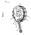
- FIG. 2 is a perspective view of a stator 40.
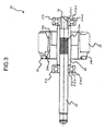
- FIG. 3 is a sectional view of a rotor 20.
- FIG. 4 is an enlarged sectional view of a counter load side end of a shaft 23.
- FIG. 5 is a diagram showing an insulating sleeve 26 ((a) is a front view and (b) is a side view).
- FIG. 6 is a diagram showing a rotor resin magnet 22 ((a) is a left side view, (b) is an A-A sectional view of (a), and (c) is a right side view).
- FIG. 1 is a sectional view of an electric motor 100.
- FIG. 2 is a perspective view of a stator 40.
- FIG. 3 is a sectional view of a rotor 20.
- FIG. 4 is an enlarged sectional view of
- FIG. 7 is a diagram showing a resin magnet for position detection 25 ((a) is a left side view, (b) is a front view, and (c) is an A section enlarged view of (b)).
- FIG. 8 is a sectional view of the rotor 20 according to a first modification.
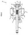
- FIG. 9 is a sectional view of the rotor 20 according to a second modification.
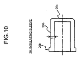
- FIG. 10 is a front view of the insulating sleeve 26 used in the rotor 20 according to the second modification.
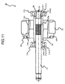
- FIG. 11 is a sectional view of the rotor 20 according to a third modification.
- FIG. 12 is a sectional view of the rotor 20 according to a fourth modification.
- FIG. 13 is a configuration diagram of a driving circuit 200 that drives the electric motor 100.
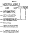
- FIG. 14 is a diagram showing a manufacturing process for the rotor 20.
- the electric motor 100 includes a mold stator 10, the rotor 20 (defined as an electric motor rotor), and a bracket 30 of metal attached to one axis direction end (hereinafter referred to just as "axis direction one end") of the mold stator 10.
- the electric motor 100 is, for example, a brushless DC motor including a permanent magnet in the rotor 20 and driven by an inverter.
- the mold stator 10 is opened at the axis direction one end (the right side in FIG. 1 ).
- the rotor 20 is inserted from this opening.
- axis direction other end At the other axis direction end (hereinafter referred to just as “axis direction other end") (the left side in FIG. 1 ) of the mold stator 10, a hole (not shown in the figure) slightly larger than the diameter of the shaft 23 of the rotor 20 is opened.
- the shaft 23 on a load side sticks out to the outside (the left side in FIG. 1 ) from the hole at the axis direction other end of the mold stator 10.
- a load side roller bearing 21a (an example of a roller bearing) of the rotor 20 is pushed in until it comes into contact with a bearing supporting section 11 at an axis direction end on a counter opening side of the mold stator 10. At this point, the load side roller bearing 21a is supported by the bearing supporting section 11 formed at the axis direction end on the counter opening end side of the mold stator 10.
- a counter load side roller bearing 21b (an example of a roller bearing) is attached to the shaft 23 on the counter load side (the right side in FIG. 1 ) (in general, attached by press-fitting).
- the insulating sleeve 26 is provided between the counter load side roller bearing 21b and the shaft 23 on the counter load side.
- the bracket 30 that closes the opening of the mold stator 10 and supports the counter load side roller bearing 21b is press-fitted into the mold stator 10.
- the bracket 30 supports the counter load side roller bearing 21b with a roller-bearing supporting section 30a.
- the press-fitting of the bracket 30 into the mold stator 10 is performed by press-fitting a press-fitting section 30b, which has a substantially ring shape and a C shape in cross section, of the bracket 30 into the opening side of an inner circumferential section 10a (a mold resin section) of the mold stator 10.
- the outer diameter of the press-fitting section 30b of the bracket 30 is larger than the inner diameter of the inner circumferential section 10a of the mold stator 10 by a press-fitting margin.
- the material of the bracket 30 is metal, for example, galvanized steel sheet. However, the material is not limited to the galvanized steel sheet.
- This embodiment has a characteristic in the structure of the rotor 20. Therefore, the mold stator 10 is explained briefly.
- the mold stator 10 includes the stator 40 and mold resin 50 for molding.
- the mold resin 50 thermosetting resin such as unsaturated polyester resin is used. Low-pressure molding is desirable for the stator 40 because the stator 40 is attached with a substrate or the like explained below and has low-strength structure. Therefore, the thermosetting resin such as the unsaturated polyester resin is used.
- the stator 40 shown in Fig. 2 has a configuration explained below.
- the rotor 20 includes the shaft 23 applied with a knurl 23a, a ring-like rotor resin magnet 22 (an example of a rotor magnet), a ring-like resin magnet for position detection 25 (an example of a magnet for position detection), and a resin section 24 for integrally molding these components.
- the ring-like rotor resin magnet 22, the shaft 23, and the resin magnet for position detection 25 are integrated by the resin section 24.
- the resin section 24 contains a center cylindrical section 24g (a section corresponding to the rotor resin magnet 22) explained below, which is formed in the outer circumference of the shaft 23, and a plurality of ribs (not shown in the figure) in the axis direction radially formed in the radial direction centering on the shaft 23 for coupling the rotor resin magnet 22 to the center cylindrical section 24g. Hollows piercing through in the axis direction are formed among the ribs.
- thermoplastic resin such as PBT (polyethylene terephthalate) or PPS (polyphenylene sulfide) is used. Materials obtained by mixing a glass filler in these kinds of resin are also suitable.
- the counter load side roller bearing 21b is attached to the shaft 23 on the counter load side (the right side in FIG. 3 ) (in general, by press-fitting).
- a load side roller bearing 21a is attached to the shaft 23 on the load side to which a fan and the like are attached (the left side in FIG. 3 ).
- the load side roller bearing 21a and the counter load side roller bearing 21b are publicly-known roller bearings.
- the load side roller bearing 21a includes an inner ring 21a-1 press-fitted into the shaft 23, an outer ring 21a-2 supported by the bearing supporting section 11 of the mold stator 10, and a rolling element 21a-3 that rolls between the inner ring 21a-1 and the outer ring 21a-2. Balls or rollers are used as the rolling element 21a-3.
- the counter load side roller bearing 21b includes an inner ring 21b-1 press-fitted into the shaft 23 via the insulating sleeve 26, an outer ring 21b-2 supported by the bearing supporting section 30a of the bracket 30, and a rolling element 21b-3 that rolls between the inner ring 21b-1 and the outer ring 21b-2. Balls or rollers are used as the rolling element 21b-3.
- This embodiment has a characteristic in interposing the insulating sleeve 26 between the counter load side roller bearing 21b supported by the bracket 30 of metal (having electric conductivity) and the shaft 23 and suppressing a shaft current using the insulating sleeve 26 as insulation to thereby suppress occurrence of electrolytic corrosion of the counter load side roller bearing 21b.
- the insulating sleeve 26 provided between the counter load side roller bearing 21b and the shaft 23 is inserted near the counter load side end of the shaft 23.
- the insulating sleeve 26 is also integrated.
- the insulating sleeve 26 inserted into the shaft 23 is integrated and fixed by the resin section 24. Therefore, the insulating sleeve 26 is fixed extremely simply and fixed surely, and it is less likely that the insulating sleeve 26 comes off the shaft 23.
- This embodiment includes the rotor 20 not including the ring-like resin magnet for position detection 25.
- the outer ring 21a-2 is supported by the bearing supporting section 11 (formed by the mold resin 50) of the mold stator 10. Therefore, stray capacitance is extremely small because the bearing supporting section is an insulating material. Consequently, a shaft current flowing through the bearing is extremely small even if the shaft 23 is not insulated.
- FIG. 4 is a sectional view showing a counter load side end of the shaft 23 in enlargement.
- a diameter d2 of a counter load side end 23d of the shaft 23, on which the counter load side roller bearing 21b is held via the resin section 24, is set smaller than a diameter d1 of a center section 23e, on which the rotor resin magnet 22 is held via the resin section 24, to provide a step 23c.
- a dimension between a counter load side end face 23f (an example of an axis direction end face) of the shaft 23 and the step 23c is longer than the thickness (the shaft direction length) of the counter load side roller bearing 21b.
- the counter load side end face 23f of the shaft 23 is exposed.
- a bearing contact surface 24d which serves as a positioning in the axis direction during insertion of the shaft 23 of the counter load side roller bearing 21b into the counter load side end 23d, is formed in a counter load side end of the center cylindrical section 24g of the resin section 24 formed in the outer circumference centering on a knurl section of the shaft 23.
- a step section 24e is provided between the outer circumferential section of the center cylindrical section 24g and the bearing contact surface 24d.
- the diameter of the step section 24e is smaller than the inner diameter of the outer ring 21b-2 of the counter load side roller bearing 21b.
- the diameter of the step section 24e is set substantially the same as or slightly smaller than the outer diameter of the inner ring 21b-1 of the counter load side roller bearing 21b.
- a cover is provided between an outer ring and an inner ring to prevent grease from leaking to the outside from the inside of the roller bearing or prevent dust and the like from intruding into the inside of the roller bearing from the outside.
- the cover is located further on the inner side than both end faces of the roller bearing.
- the diameter of the step section 24e is practically set substantially the same as or slightly smaller than the outer diameter of the inner ring 21b-1 of the counter load side roller bearing 21b.
- the bearing contact surface 24d of the center cylindrical section 24g of the resin section 24 is formed by a bush
- the bearing contact surface 24d is formed by the bush up to the step section 24e. Therefore, a fitting surface of a die becomes a counter load side end face 24h of the center cylindrical section 24g. Therefore, even if burrs occur on the fitting surface of the die, because the counter load side roller bearing 21b is separated from the counter load side end face 24h, which is the fitting surface of the die, of the step section 24e, the burrs do not come into contact with the counter load side roller bearing 21b. Therefore, it is less likely that the counter load side roller bearing 21b is adversely affected.
- the center cylindrical section 24g of the resin section 24 is cracked.
- the diameter of the step section 24e is set smaller than the inner diameter of the outer rings 21a-2 and 21b-2 of the load side roller bearing 21a and the counter load side roller bearing 21b. Therefore, the thickness in the radial direction of the center cylindrical section 24g in the step section 24e can be set larger than the inner diameter of the outer rings 21a-2 and 21b-2.
- the insulating sleeve 26 has a substantially cylindrical shape.
- a brim section 26b ((a) and (b) of FIG. 5 ) having a diameter larger than an outer circumferential section 26a of the insulating sleeve 26 is provided at an end on the center cylindrical section 24g side of the resin section 24.
- the center cylindrical section 24g covers and integrates the brim section 26b of the insulating sleeve 26. Therefore, the movement in the axis direction of the insulating sleeve 26 is suppressed.
- the brim section 26b of the insulating sleeve 26 includes substantially flat cutout sections 26b-1 in, for example, four places at substantially equal intervals in the circumferential direction. Consequently, the movement in the circumferential direction of the insulating sleeve 26 is suppressed.
- the number, the shape, and the arrangement interval of the cutout sections 26b-1 can be arbitrary.
- PBT polybutylene terephthalate
- PPS polyphenylene sulfide
- LCP liquid crystal polymer
- Thickness d ((a) of FIG. 5 ) in the radial direction of the insulating sleeve 26 is, for example, 1 to 1.5 millimeters. However, the thickness d is not limited to this range.
- FIG. 6 is a diagram showing the rotor resin magnet 22.
- (a) of FIG. 6 is a left side view
- (b) of FIG. 6 is an A-A sectional view of (a) of FIG. 6,
- (c) of FIG. 6 is a right side view.
- the configuration of the ring-like rotor resin magnet 22 is explained with reference to FIG. 6 .
- cutouts 22a for securing coaxiality of the shaft 23 and the rotor resin magnet 22 during die closing in resin molding are formed at axis direction one end of the inner diameter of the rotor resin magnet 22 (the right side in (b) of FIG. 6 ).
- the cutouts 22a are formed in eight places in the circumferential direction at substantially equal intervals ((c) of FIG. 6 ).
- pedestals 22b on which the resin magnet for position detection 25 is set are formed in the circumferential direction at substantially equal intervals on an end face at the axis direction other end (the left side in (b) of FIG. 6 ).
- the pedestals 22b are formed from places near the inner diameter of the rotor resin magnet 22 toward the outer diameter.
- Positioning protrusions 22c extend in the radial direction from the distal ends of the pedestals 22b toward places near the outer circumferential section of the rotor resin magnet 22.
- the positioning protrusions 22c are used for positioning in the circumferential direction (the rotating direction) of the rotor resin magnet 22 when the rotor magnet, the magnet for position detection, and the shaft are integrally molded by the resin section 24.
- FIG. 7 The configuration of the ring-like resin magnet for position detection 25 is explained with reference to FIG. 7.
- (a) of FIG. 7 is a left side view of the resin magnet for position detection 25.
- (b) of FIG. 7 is a front view of the resin magnet for position detection 25.
- (c) of FIG. 7 is an A section enlarged view of (b) of FIG. 7 .
- the resin magnet for position detection 25 includes steps 25b at axis direction both ends on the inner diameter side.
- the steps 25b are necessary because a part of the resin section 24 is filled in the step 25b on an axis direction end side of the rotor 20 and prevents the resin magnet for position detection 25 from coming off in the axis direction.
- the resin magnet for position detection 25 including the steps 25b at both ends is shown.
- the step 25b only has to be present at one of the ends and located on the axis direction end side of the rotor 20.
- the resin magnet for position detection 25 including the steps 25b at both the ends is excellent in workability because it is possible to set the resin magnet for position detection 25 without worrying about the front and the back thereof in setting the resin magnet for position detection 25 in a die during the integral molding of the rotor 20 by the resin section 24.
- the resin magnet for position detection 25 includes, in the steps 25b, at substantially equal intervals in the circumferential direction, eight ribs 25a (substantially triangular in cross section) that function as a whirl-stop in the circumferential direction when embedded in the resin section 24.
- the number, the shape, and the arrangement interval of the ribs 25a can be arbitrary.
- a resin injecting section 24c for resin injection during resin molding are formed after the resin molding.
- the rotor resin magnet 22 is molded by mixing a magnetic material in thermoplastic resin. As showing in FIG. 6 , the cutouts 22a are provided in a taper shape in the inner diameter from axis direction one end face.
- the pedestals 22b on which the resin magnet for position detection 25 is set are provided on the axis direction other end face on the opposite side of the axis direction one end face where the cutouts 22a are provided.
- the resin magnet for position detection 25 can be separated from the end face of the rotor resin magnet 22 by the pedestals 22b of the rotor resin magnet 22 integrally molded with the shaft 23.
- the thickness of the resin magnet for position detection 25 can be minimized and the resin magnet for position detection 25 can be arranged in an arbitrary position. Costs can be reduced by filling the thermoplastic resin more inexpensive than the rotor resin magnet 22.
- the resin magnet for position detection 25 includes the steps 25b on both the sides in the thickness direction and includes, in the steps 25b on both the sides, the ribs 25a that function as a whirl-stop when embedded with resin.
- the coaxiality of the inner diameter of the resin magnet for position detection 25 and the outer diameter of the resin magnet for position detection 25 is accurately set.
- the resin (the resin section 24) is filled in a taper shape in the outer circumference of the resin magnet for position detection 25 to cope with fluctuation in the outer circumference of the resin magnet for position detection 25.
- the filled resin is blocked by an axis direction end face (the outer side) on one side of the resin magnet for position detection 25 and the axis direction both end faces of the rotor resin magnet 22. Therefore, it is possible to suppress burrs from occurring on the outer diameter of the rotor resin magnet 22 and improvement of quality is realized.
- a gate port used during the integral molding with the shaft 23 is arranged further on the inner side than the inner diameter of the rotor resin magnet 22 and the resin injecting section 24c is arranged in a convex shape. Therefore, concentration of pressure is relaxed, the resin is easily filled, and the convex section of the resin injecting section 24c can be used for positioning as well.
- FIG. 8 is a sectional view of the rotor 20 according to a first modification.
- the rotor 20 according to the first modification is different from the rotor 20 shown in FIG. 3 in that a center hole 23b is formed at the counter load side end of the shaft 23.
- the center hole 23b of the shaft 23 is set in a die (an upper die). Consequently, the coaxiality of the rotor resin magnet 22 and the shaft 23 is improved.
- Center holes 23b can be formed at both the ends of the shaft 23.
- FIG. 9 is a sectional view of the rotor 20 according to a second modification.
- the rotor 20 according to the second modification is different from the rotor 20 shown in FIG. 3 in that the insulating sleeve 26 covers the entire counter load side end 23d of the shaft 23.
- the insulating sleeve 26 is formed in a cap shape opened at one end in the axis direction and closed at the other end. Therefore, during the molding of the rotor 20 by the resin section 24, an end face 26c of the insulating sleeve 26 is pressed by a die.
- An advantage of the insulating sleeve 26 shown in FIG. 10 is that, even if the diameter d2 of the counter load side end 23d of the shaft 23 where the counter load side roller bearing 21b is held via the insulating sleeve 26 and the shaft diameter d1 of the center cylindrical section 24g are the same and the step 23c ( FIG. 4 ) is not provided, when the insulating sleeve 26 is inserted into the shaft 23, a position in the axis direction of the insulating sleeve 26 with respect to the shaft 23 is determined by pushing in the insulating sleeve 26 until the insulating sleeve 26 comes into contact with the end face of the counter load side end 23d of the shaft 23.
- FIG. 11 is a sectional view of the rotor 20.
- the rotor 20 is different from the rotor 20 shown in FIG. 9 in that a center hole 23b is formed at the counter load side end of the shaft 23.
- the rotor resin magnet 22, and the resin magnet for position detection 25 are integrated (molded) by the resin section 24, the coaxiality of the rotor resin magnet 22 and the shaft 23 is improved by setting the center hole 23b of the shaft 23 in the die (the upper die).
- FIG. 12 is a sectional view of the rotor 20 according to a fourth modification.
- the rotor 20 according to the fourth modification is different from the rotor 20 shown in FIG. 3 in that the insulating sleeve 26 is interposed between the load side roller bearing 21a and the shaft 23 as well to insulate the load side roller bearing 21a and the shaft 23.
- the rotor 20 By configuring the rotor 20 as shown in FIG. 12 , it is possible to further reduce the shaft current in the load side roller bearing 21a. Further, it is possible to reduce, using a steel sheet frame in a section other than the mold stator 10, for example, the external hull, a shaft current of an electric motor in which brackets of metal are used on a load side and a counter load side.
- the configuration of the counter load side end 23d of the shaft 23 is the same as the configuration shown in FIG. 3 .
- the other configurations shown in FIGS. 8 , 9 , and 11 can be adopted.
- the mold stator 10 side is the load side and the bracket 30 side is the counter load side.
- the load side and the counter load side can be opposite.
- the rotor resin magnet 22 molded by mixing the magnetic material in the thermoplastic resin is used as the permanent magnet.
- other permanent magnets rare earth magnets (neodymium and samarium cobalt), ferrite, etc.) can be used.
- the other permanent magnets can be used as the resin magnet for position detection 25.
- the other permanent magnets rare earth magnets (neodymium and samarium cobalt), ferrite, etc.
- the carrier frequency of the inverter is set high.
- a shaft voltage generated based on high-frequency induction in a shaft of the electric motor increases and a potential difference present between an inner ring and an outer ring of a roller bearing that supports the shaft increases. Therefore, an electric current easily flows to the roller bearing.
- the electric current flowing to the roller bearing causes corrosion called electrolytic corrosion on both tracks of the inner ring and the outer ring and a rolling contact surface of a rolling element (a ball or a roller that rolls between the inner and outer rings) and deteriorates the durability of the roller bearing.
- the rotor 20 according to this embodiment is particularly effective for a reduction in the shaft current when the electric motor 100 is operated using the inverter.
- FIG. 13 is a configuration diagram of the driving circuit 200 that drives the electric motor 100.
- the driving circuit 200 of an inverter system includes a position detecting circuit 110, a waveform generating circuit 120, a pre-driver circuit 130, and a power circuit 140.
- the position detecting circuit 110 detects a magnetic pole of the resin magnet for position detection 25 of the rotor 20 using the Hall IC 49b.
- the waveform generating circuit 120 generates, based on a speed instruction signal for instructing rotating speed of the rotor 20 and a position detection signal from the position detecting circuit 110, a PWM (Pulse Width Modulation) signal for performing inverter driving and outputs the PWM signal to the pre-driver circuit 130.
- a PWM Pulse Width Modulation
- the pre-driver circuit 130 outputs a transistor driving signal for driving transistors 141 (six) of the power circuit 140.
- the power circuit 140 includes a direct-current power supply input section and arms including inverter output sections and formed by connecting the transistors 141 and diodes 142 in parallel and further connecting the connected transistors 141 and diodes 142 in series.
- the inverter output sections of three arms are connected to the respective coils 42.
- Direct-current power supplies +, - of 140 V or 280 V obtained by rectifying alternating-current 100 V or 200 V of a commercial power supply are connected to the direct-current power supply input section.
- the waveform generating circuit 120 sets electric conduction timing to the coils 42 of the three phases according to the position detection signal and generates and outputs a PWM signal corresponding to the input of the speed instruction signal.
- the pre-driver circuit 130 that receives the input of the PWM signal drives the transistors 141 in the power circuit 140.
- the inverter output sections drive the transistors 141 to apply a voltage to the coils 42.
- An electric current flows to the coils 42, torque is generated, and the rotor 20 rotates.
- the electric motor 100 rotates at rotating speed corresponding to the speed instruction signal.
- the electric motor 100 is also stopped according to the speed instruction signal.
- FIG. 14 A manufacturing process for the rotor 20 is shown in FIG. 14 .
- the resin magnet for position detection 25 can be separated from the end face of the rotor resin magnet 22 by the pedestals 22b of the rotor resin magnet 22.
- the thickness of the resin magnet for position detection 25 can be minimized and the resin magnet for position detection 25 can be arranged in an arbitrary position. Costs can be reduced by filling the thermoplastic resin more inexpensive than the rotor resin magnet 22.
- the resin magnet for position detection 25 is symmetrical in the thickness direction, the resin magnet for position detection 25 can be set in the die without adjusting the direction of the resin magnet for position detection 25.
- a section where the outer diameter passes when the resin magnet for position detection 25 for the lower die is set is tapered to be wide in an opening (the taper section 24b of the resin section 24). Therefore, because the resin magnet for position detection 25 can be set without being caught by the lower die, it is possible to reduce costs according to improvement of productivity through simplification of a work process.
- the inner diameter is held by the inner-diameter pressing section provided in the lower die. Consequently, the accuracy of the coaxiality of the shaft 23 and the rotor resin magnet 22 is secured.
- the cutout pressing section provided in the upper die presses the cutouts 22a provided in the inner diameter of the rotor resin magnet 22. Consequently, the accuracy of the coaxiality of the shaft 23 and the rotor resin magnet 22 is secured.
- the insulating sleeve 26 is interposed between the counter load side roller bearing 21b supported by the bracket 30 of metal (having electric conductivity) and the shaft 23.
- the insulating sleeve 26 is integrated with the resin section 24.
- the counter load side roller bearing 21b and the shaft 23 are insulated by the insulating sleeve 26 and the shaft current is suppressed. Consequently, it is possible to suppress occurrence of electrolytic corrosion of the counter load side roller bearing 21b.
- the same effect can be obtained when the ring-like resin magnet for position detection 25 is integrated together with the shaft 23 and the ring-like rotor resin magnet 22 by the resin section 24.
- the step section 24e is provided between the center cylindrical section 24g of the resin section 24, which is formed in the outer circumference of the center section 23e of the shaft 23, and the bearing contact surface 24d. Consequently, when the shaft 23, the rotor resin magnet 22, and the resin magnet for position detection 25 are integrally molded by the resin, if the bearing contact surface 24d of the center cylindrical section 24g of the resin section 24 is formed by a bush, the bearing contact surface 24d is formed by the bush up to the step section 24e. Therefore, the fitting surface of the die becomes the counter load side end face 24h of the center cylindrical section 24g.
- the counter load side roller bearing 21b is separated from the counter load side end face 24h, which is the fitting surface of the die, by the step section 24e, even if burrs occur on the fitting surface of the die, the burrs do not come into contact with the counter load side roller bearing 21b. Therefore, it is less likely that the counter load side roller bearing 21b is adversely affected.
- the center cylindrical section 24g of the resin section 24 is cracked.
- it is possible to cope with such a case by providing the step section 24e in the center cylindrical section 24g and increasing the thickness in the radial direction of the center cylindrical section 24g in the step section 24e.
- the center hole 23b is formed at the counter load side end of the shaft 23. Consequently, when the shaft 23, the rotor resin magnet 22, and the resin magnet for position detection 25 are integrally molded by the resin, the protrusion to be fit in the center hole 23b, the coaxiality of which with the shaft inserting section provided in the die (the upper die) is secured, is fit in the center hole 23b of the shaft 23. Therefore, it is possible to hold the shaft 23 in a state in which the coaxiality is secured. The coaxiality of the rotor resin magnet 22 and the shaft 23 is improved.
- the insulating sleeve 26 can cover the entire counter load side end 23d of the shaft 23.
- the insulating sleeve 26 is formed in the cap shape opened at one end in the axis direction and closed at the other end. Therefore, during the molding of the rotor 20 by the resin section 24, the end face 20c of the insulating sleeve 26 is pressed by the die.
- the insulating sleeve 26 covers the entire counter load side end 23d of the shaft 23 and the center hole 23b is formed at the counter load side end of the shaft 23. Therefore, when the shaft 23 in which the insulating sleeve 26 is inserted, the rotor resin magnet 22, and the resin magnet for position detection 25 are integrated (molded) by the resin section 24, the center hole 23b of the shaft 23 is set in the die (the upper die). Consequently, the coaxiality of the rotor resin magnet 22 and the shaft 23 is improved.
- the insulating sleeve 26 is interposed between the load side roller bearing 21a and the shaft 23 as well to insulate the load side roller bearing 21a and the shaft 23. Consequently, it is possible to further reduce the shaft current in the load side roller bearing 21a. It is possible to set the carrier frequency of the inverter higher. Further, it is possible to reduce, using a steel sheet frame in a section other than the mold stator 10, for example, the external hull, a shaft current of an electric motor in which brackets of metal are used on a load side and a counter load side.
- the carrier frequency of the inverter is set high.
- a shaft voltage generated based on high-frequency induction in a shaft of the electric motor increases and a potential difference present between an inner ring and an outer ring of a roller bearing that supports the shaft increases. Therefore, an electric current flowing to the roller bearing also increases. Therefore, the rotor 20 according to this embodiment is particularly effective for a reduction in the shaft current generated when the electric motor 100 is operated using the inverter.
- a method of detecting the magnetic pole of the resin magnet for position detection 25 of the rotor 20 using the Hall IC 49b, which is a sensor for detecting the magnetic pole, is explained above.
- the resin magnet for position detection 25 can be separated from the end face of the rotor resin magnet 22 by the pedestals 22b of the rotor resin magnet 22.
- the thickness of the resin magnet for position detection 25 can be minimized and the resin magnet for position detection 25 can be arranged in an arbitrary position. Costs can be reduced by filling the thermoplastic resin more inexpensive than the rotor resin magnet 22.
- the resin magnet for position detection 25 is symmetrical in the thickness direction, the resin magnet for position detection 25 can be set in the die without adjusting the direction of the resin magnet for position detection 25.
- a section where the outer diameter passes when the resin magnet for position detection 25 for the lower die is set is tapered to be wide in an opening (the taper section 24b of the resin section 24). Therefore, because the resin magnet for position detection 25 can be set without being caught by the lower die, it is possible to reduce costs according to improvement of productivity through simplification of a work process.
- the inner diameter is held by the inner-diameter pressing section provided in the lower die. Consequently, the accuracy of the coaxiality of the shaft 23 and the rotor resin magnet 22 is secured.
- the cutout pressing section provided in the upper die presses the cutouts 22a provided in the inner diameter of the rotor resin magnet 22. Consequently, the accuracy of the coaxiality of the shaft 23 and the rotor resin magnet 22 is secured.
- FIG. 15 is a diagram showing a second embodiment and is a configuration diagram of an air conditioner 300.
- the air conditioner 300 includes indoor equipment 310 and outdoor equipment 320 connected to the indoor equipment 310.
- a fan for indoor equipment (not shown in the figure) is mounted on the indoor equipment 310.
- a fan for outdoor equipment 330 is mounted on the outdoor equipment 320.
- the fan for outdoor equipment 330 and the fan for indoor equipment include the electric motor 100 according to the first embodiment as a driving source.
- the electric motor 100 according to the first embodiment is mounted on the fan for outdoor equipment 330 and the fan for indoor equipment, which are main components of the air conditioner 300. Consequently, the durability of the air conditioner 300 is improved.
- the electric motor 100 can be used while being mounted on a ventilation fan, a household electric appliance, a machine tool, or the like.
Landscapes
- Engineering & Computer Science (AREA)
- Power Engineering (AREA)
- Microelectronics & Electronic Packaging (AREA)
- Motor Or Generator Frames (AREA)
- Manufacture Of Motors, Generators (AREA)
Abstract
Description
- The present invention relates to an electric motor rotor in which a roller bearing is used and relates to an electric motor rotor suitable for an electric motor driven by an inverter. Further, the present invention relates to an electric motor in which the electric motor rotor is used, a method of manufacturing the electric motor rotor, and an air conditioner mounted with the electric motor.
- Conventionally, when an electric motor is operated using an inverter, for the purpose of realizing a reduction in noise of the electric motor caused according to switching of transistors in a power circuit, a carrier frequency of the inverter is set high. As the carrier frequency is set higher, a shaft voltage generated based on high-frequency induction in a shaft of the electric motor increases and a potential difference present between an inner ring and an outer ring of a roller bearing that supports the shaft increases. Therefore, an electric current easily flows to the roller bearing. There is a problem in that the electric current flowing to the roller bearing causes corrosion called electrolytic corrosion on both tracks of the inner ring and the outer ring and a rolling contact surface of a rolling element (balls or rollers that roll between the inner and outer rings) and deteriorates the durability of the roller bearing.
- Therefore, to obtain an electric motor having a simple configuration and easily assembled that can prevent an electric current from flowing to a roller bearing provided between a shaft and a motor case and prevent electrolytic corrosion from occurring in the roller bearing, an electric motor including a stator formed by winding a coil, a frame that fixes the stator, a rotor opposed to the stator via a very small air gap, a shaft fixedly attached with the rotor and rotatably born via the roller bearing, and a bearing bracket that supports the roller bearing via an insulating material is provided, wherein a concave section is provided on a side of the bearing bracket in contact with the insulating material, and a convex section corresponding to the concave section of the bearing bracket is provided in the insulating material, such that the convex section of the insulating material is fit in the concave section of the bearing bracket and fixed (see, for example, Patent Literature 1).
- An electrolytic corrosion preventing roller bearing in which an insulating coating film is formed on an inner ring fitting surface or an outer ring fitting surface of a roller bearing or both of the inner ring fitting surface and the outer ring fitting surface is proposed, wherein a boundary surface between a circumferential surface of the inner ring fitting surface or a circumferential surface of the outer ring fitting surface and a chamfered section assumes a gentle taper surface or an arcuate surface having a large curvature radius, and the electrolytic corrosion preventing roller bearing has, on at least one fitting surface, an insulating coating film of an inorganic compound by thermal spraying (see, for example, Patent Literature 2).
-
- Patent Literature 1: Japanese Patent Application Laid-open No.
2000-156952 - Patent Literature 2: Japanese Patent Application Laid-open No.
59-103023 - However, the electric motor disclosed in
Patent Literature 1 has the configuration in which the concave section is provided on the side of the bearing bracket in contact with the insulating material, the convex section corresponding to the concave section of the bearing bracket is provided in the insulating material, and the convex section of the insulating material is fitted and fixed in the concave section of the bearing bracket. Therefore, there is a problem in that, although the electric motor has a single configuration and is easily assembled, the insulating material easily comes off the bearing bracket. - In the electrolytic corrosion preventing roller bearing disclosed in
Patent Literature 2, the boundary surface between the circumferential surface of the inner ring fitting surface or the peripheral surface of the outer ring fitting surface and the chamfered section assumes the gentle taper surface or the arcuate surface having the large curvature radius and the insulating coating film of the inorganic compound by thermal spraying is formed on at least one fitting surfaces. Therefore, there is a problem in that costs increase. - The present invention has been devised to solve the problems explained above and it is an object of the present invention to provide an electric motor rotor, an electric motor, a method of manufacturing the electric motor rotor, and an air conditioner in which an insulating sleeve applied to a shaft for performing insulation between a roller bearing and a shaft to suppress electrolytic corrosion of a bearing can be surely fixed by a simple method.
- In order to solve the aforementioned problems, an electric motor rotor, in which a rotor magnet and a shaft are integrated by a resin section and roller bearings are arranged in the shaft, according to one aspect of the present invention is constructed such that an insulating sleeve is provided between the shaft and the roller bearings, and the insulating sleeve is integrated and fixed by the resin section.
- In the electric motor rotor according to the present invention, the insulating sleeve is provided between the shaft and the roller bearing and integrated and fixed by the resin section. Therefore, there is an effect of preventing a shaft current flowing through the roller bearing, suppressing electrolytic corrosion, and preventing occurrence of abnormal sound. Further, there is an effect that the insulating sleeve can be surely fixed by a simple method.
-
-
FIG. 1 is a diagram showing a first embodiment and is a sectional view of anelectric motor 100. -
FIG. 2 is a diagram showing the first embodiment and is a perspective view of astator 40. -
FIG. 3 is a diagram showing the first embodiment and is a sectional view of arotor 20. -
FIG. 4 is a diagram showing the first embodiment and is an enlarged sectional view of a counter load side end of ashaft 23. -
FIG. 5 is a diagram showing the first embodiment and is a diagram showing an insulating sleeve 26 ((a) is a front view and (b) is a side view). -
FIG. 6 is a diagram showing the first embodiment and is a diagram showing a rotor resin magnet 22 ((a) is a left side view, (b) is an A-A sectional view of (a), and (c) is a right side view). -
FIG. 7 is a diagram showing the first embodiment and is a diagram showing a resin magnet for position detection 25 ((a) is a left side view, (b) is a front view, and (c) is an A section enlarged view of (b)). -
FIG. 8 is a diagram showing the first embodiment and is a sectional view of therotor 20 according to a first modification. -
FIG. 9 is a diagram showing the first embodiment and is a sectional view of therotor 20 according to a second modification. -
FIG. 10 is a diagram showing the first embodiment and is a front view of theinsulating sleeve 26 used in therotor 20 according to the second modification. -
FIG. 11 is a diagram showing the first embodiment and is a sectional view of therotor 20 according to a third modification. -
FIG. 12 is a diagram showing the first embodiment and is a sectional view of therotor 20 according to a fourth modification. -
FIG. 13 is a diagram showing the first embodiment and is a configuration diagram of adriving circuit 200 that drives theelectric motor 100. -
FIG. 14 is a diagram showing the first embodiment and is a diagram showing a manufacturing process for therotor 20. -
FIG. 15 is a diagram showing a second embodiment and is a configuration diagram of anair conditioner 300. -
FIGS. 1 to 14 are diagrams showing a first embodiment.FIG. 1 is a sectional view of anelectric motor 100.FIG. 2 is a perspective view of astator 40.FIG. 3 is a sectional view of arotor 20.FIG. 4 is an enlarged sectional view of a counter load side end of ashaft 23.FIG. 5 is a diagram showing an insulating sleeve 26 ((a) is a front view and (b) is a side view).FIG. 6 is a diagram showing a rotor resin magnet 22 ((a) is a left side view, (b) is an A-A sectional view of (a), and (c) is a right side view).FIG. 7 is a diagram showing a resin magnet for position detection 25 ((a) is a left side view, (b) is a front view, and (c) is an A section enlarged view of (b)).FIG. 8 is a sectional view of therotor 20 according to a first modification.FIG. 9 is a sectional view of therotor 20 according to a second modification.FIG. 10 is a front view of theinsulating sleeve 26 used in therotor 20 according to the second modification.FIG. 11 is a sectional view of therotor 20 according to a third modification.FIG. 12 is a sectional view of therotor 20 according to a fourth modification.FIG. 13 is a configuration diagram of adriving circuit 200 that drives theelectric motor 100.FIG. 14 is a diagram showing a manufacturing process for therotor 20. - The configuration of the
electric motor 100 is explained. As shown inFIG. 1 , theelectric motor 100 includes amold stator 10, the rotor 20 (defined as an electric motor rotor), and abracket 30 of metal attached to one axis direction end (hereinafter referred to just as "axis direction one end") of themold stator 10. Theelectric motor 100 is, for example, a brushless DC motor including a permanent magnet in therotor 20 and driven by an inverter. - The
mold stator 10 is opened at the axis direction one end (the right side inFIG. 1 ). Therotor 20 is inserted from this opening. At the other axis direction end (hereinafter referred to just as "axis direction other end") (the left side inFIG. 1 ) of themold stator 10, a hole (not shown in the figure) slightly larger than the diameter of theshaft 23 of therotor 20 is opened. In therotor 20 inserted from the axis direction one end of themold stator 10, theshaft 23 on a load side sticks out to the outside (the left side inFIG. 1 ) from the hole at the axis direction other end of themold stator 10. A load side roller bearing 21a (an example of a roller bearing) of therotor 20 is pushed in until it comes into contact with abearing supporting section 11 at an axis direction end on a counter opening side of themold stator 10. At this point, the loadside roller bearing 21a is supported by thebearing supporting section 11 formed at the axis direction end on the counter opening end side of themold stator 10. - In the
rotor 20, a counter loadside roller bearing 21b (an example of a roller bearing) is attached to theshaft 23 on the counter load side (the right side inFIG. 1 ) (in general, attached by press-fitting). - As explained below in detail, the insulating
sleeve 26 is provided between the counter loadside roller bearing 21b and theshaft 23 on the counter load side. - The
bracket 30 that closes the opening of themold stator 10 and supports the counter loadside roller bearing 21b is press-fitted into themold stator 10. Thebracket 30 supports the counter loadside roller bearing 21b with a roller-bearing supportingsection 30a. The press-fitting of thebracket 30 into themold stator 10 is performed by press-fitting a press-fittingsection 30b, which has a substantially ring shape and a C shape in cross section, of thebracket 30 into the opening side of an inner circumferential section 10a (a mold resin section) of themold stator 10. The outer diameter of the press-fittingsection 30b of thebracket 30 is larger than the inner diameter of the inner circumferential section 10a of themold stator 10 by a press-fitting margin. The material of thebracket 30 is metal, for example, galvanized steel sheet. However, the material is not limited to the galvanized steel sheet. - This embodiment has a characteristic in the structure of the
rotor 20. Therefore, themold stator 10 is explained briefly. - The
mold stator 10 includes thestator 40 andmold resin 50 for molding. As themold resin 50, thermosetting resin such as unsaturated polyester resin is used. Low-pressure molding is desirable for thestator 40 because thestator 40 is attached with a substrate or the like explained below and has low-strength structure. Therefore, the thermosetting resin such as the unsaturated polyester resin is used. - The
stator 40 shown inFig. 2 has a configuration explained below. - (1) A belt-like
stator iron core 41 in which an electromagnetic steel sheet having thickness of about 0.1 to 0.7 millimeter is perforated in a belt shape and laminated by caulking, welding, bonding, or the like is manufactured. The belt-likestator iron core 41 includes a plurality of teeth (not shown). The inner side to which a - concentratedly-
wound coil 42 explained below is applied is the teeth. - (2) An insulating
section 43 is applied to the teeth. The insulatingsection 43 is molded integrally with or separately from thestator iron core 41 using thermoplastic resin such as PBT (polybulylene terephthalate). - (3) The concentratedly-
wound coil 42 is wound around the teeth to which the insulatingsection 43 is applied. A plurality of the concentratedly-wound coils 42 are connected to form winding of three-phase single Y connection. However, distributed winding is also acceptable. - (4) Because the winding is the three-phase single Y connection, terminals 44 (
power supply terminals 44a to which a power supply is supplied andneutral terminals 44b to which the coils of respective phases (a U phase, a V phase, and a W phase) are connected) are assembled to the connection side of the insulatingsection 43. There are threepower supply terminals 44a and threeneutral terminals 44b. - (5) A
substrate 45 is attached to the insulatingsection 43 on the connection side (a side to which the terminals 44 are assembled). Thesubstrate 45 assembled with a leadwire leading component 46 for leading alead wire 47 is assembled to the insulatingsection 43 to configure thestator 40. A chamferedsquare pillar 48 of the insulatingsection 43 formed in thestator iron core 41 is inserted into a square pillar insertion hole (not shown in the figure) included in thesubstrate 45, whereby positioning in a rotating direction is performed. Thesubstrate 45 is set on a substrate setting surface (not shown) of the insulatingsection 43, whereby a position in the axis direction is determined. Thesubstrate 45 and the insulatingsection 43 are fixed by thermally welding thesquare pillar 48 projecting from thesubstrate 45 and are electrically jointed by soldering a section of the terminals 44 included in thestator 40 projecting from thesubstrate 45. AnIC 49a (a driving element) that drives the electric motor 100 (e.g., a brushless DC motor), aHall IC 49b (a position detecting element) that detects the position of therotor 20, and the like are mounted on thesubstrate 45. TheIC 49a, theHall IC 49b, and the like are defined as electronic components. - The configuration of the
rotor 20 is explained. As shown inFIG. 3 , therotor 20 includes theshaft 23 applied with aknurl 23a, a ring-like rotor resin magnet 22 (an example of a rotor magnet), a ring-like resin magnet for position detection 25 (an example of a magnet for position detection), and aresin section 24 for integrally molding these components. - The ring-like
rotor resin magnet 22, theshaft 23, and the resin magnet forposition detection 25 are integrated by theresin section 24. At this point, theresin section 24 contains a centercylindrical section 24g (a section corresponding to the rotor resin magnet 22) explained below, which is formed in the outer circumference of theshaft 23, and a plurality of ribs (not shown in the figure) in the axis direction radially formed in the radial direction centering on theshaft 23 for coupling therotor resin magnet 22 to the centercylindrical section 24g. Hollows piercing through in the axis direction are formed among the ribs. - As resin used in the
resin section 24, thermoplastic resin such as PBT (polyethylene terephthalate) or PPS (polyphenylene sulfide) is used. Materials obtained by mixing a glass filler in these kinds of resin are also suitable. - The counter load
side roller bearing 21b is attached to theshaft 23 on the counter load side (the right side inFIG. 3 ) (in general, by press-fitting). A loadside roller bearing 21a is attached to theshaft 23 on the load side to which a fan and the like are attached (the left side inFIG. 3 ). - The load
side roller bearing 21a and the counter loadside roller bearing 21b are publicly-known roller bearings. - The load
side roller bearing 21a includes aninner ring 21a-1 press-fitted into theshaft 23, anouter ring 21a-2 supported by thebearing supporting section 11 of themold stator 10, and a rollingelement 21a-3 that rolls between theinner ring 21a-1 and theouter ring 21a-2. Balls or rollers are used as the rollingelement 21a-3. - The counter load
side roller bearing 21b includes aninner ring 21b-1 press-fitted into theshaft 23 via the insulatingsleeve 26, anouter ring 21b-2 supported by thebearing supporting section 30a of thebracket 30, and a rollingelement 21b-3 that rolls between theinner ring 21b-1 and theouter ring 21b-2. Balls or rollers are used as the rollingelement 21b-3. - This embodiment has a characteristic in interposing the insulating
sleeve 26 between the counter loadside roller bearing 21b supported by thebracket 30 of metal (having electric conductivity) and theshaft 23 and suppressing a shaft current using the insulatingsleeve 26 as insulation to thereby suppress occurrence of electrolytic corrosion of the counter loadside roller bearing 21b. - Further, the insulating
sleeve 26 provided between the counter loadside roller bearing 21b and theshaft 23 is inserted near the counter load side end of theshaft 23. When theshaft 23, the ring-likerotor resin magnet 22, and the ring-like resin magnet forposition detection 25 are integrated by theresin section 24, the insulatingsleeve 26 is also integrated. - In this way, the insulating
sleeve 26 inserted into theshaft 23 is integrated and fixed by theresin section 24. Therefore, the insulatingsleeve 26 is fixed extremely simply and fixed surely, and it is less likely that the insulatingsleeve 26 comes off theshaft 23. - This embodiment includes the
rotor 20 not including the ring-like resin magnet forposition detection 25. - In the load
side roller bearing 21a, theouter ring 21a-2 is supported by the bearing supporting section 11 (formed by the mold resin 50) of themold stator 10. Therefore, stray capacitance is extremely small because the bearing supporting section is an insulating material. Consequently, a shaft current flowing through the bearing is extremely small even if theshaft 23 is not insulated. -
FIG. 4 is a sectional view showing a counter load side end of theshaft 23 in enlargement. InFIG. 4 , a diameter d2 of a counterload side end 23d of theshaft 23, on which the counter loadside roller bearing 21b is held via theresin section 24, is set smaller than a diameter d1 of acenter section 23e, on which therotor resin magnet 22 is held via theresin section 24, to provide astep 23c. - A dimension between a counter load
side end face 23f (an example of an axis direction end face) of theshaft 23 and thestep 23c is longer than the thickness (the shaft direction length) of the counter loadside roller bearing 21b. In an example shown inFIG. 4 , the counter loadside end face 23f of theshaft 23 is exposed. - In the
resin section 24, a bearingcontact surface 24d, which serves as a positioning in the axis direction during insertion of theshaft 23 of the counter loadside roller bearing 21b into the counterload side end 23d, is formed in a counter load side end of the centercylindrical section 24g of theresin section 24 formed in the outer circumference centering on a knurl section of theshaft 23. - In the center
cylindrical section 24g of theresin section 24 formed in the outer circumference centering on the Knurl section of theshaft 23, astep section 24e is provided between the outer circumferential section of the centercylindrical section 24g and the bearingcontact surface 24d. - It is essential that the diameter of the
step section 24e is smaller than the inner diameter of theouter ring 21b-2 of the counter loadside roller bearing 21b. In therotor 20 shown inFIG. 3 , the diameter of thestep section 24e is set substantially the same as or slightly smaller than the outer diameter of theinner ring 21b-1 of the counter loadside roller bearing 21b. - In general, in a roller bearing, a cover is provided between an outer ring and an inner ring to prevent grease from leaking to the outside from the inside of the roller bearing or prevent dust and the like from intruding into the inside of the roller bearing from the outside. The cover is located further on the inner side than both end faces of the roller bearing.
- Therefore, even if the diameter of the
step section 24e is set larger than the outer diameter of theinner ring 21b-1 of the counter loadside roller bearing 21b, a section larger than the outer diameter of theinner ring 21b-1 does not come into contact with the counter loadside roller bearing 21b. Therefore, the diameter of thestep section 24e is practically set substantially the same as or slightly smaller than the outer diameter of theinner ring 21b-1 of the counter loadside roller bearing 21b. - By providing the
step section 24e, when theshaft 23, therotor resin magnet 22, and the resin magnet forposition detection 25 are integrally molded by resin, if the bearingcontact surface 24d of the centercylindrical section 24g of theresin section 24 is formed by a bush, the bearingcontact surface 24d is formed by the bush up to thestep section 24e. Therefore, a fitting surface of a die becomes a counter loadside end face 24h of the centercylindrical section 24g. Therefore, even if burrs occur on the fitting surface of the die, because the counter loadside roller bearing 21b is separated from the counter loadside end face 24h, which is the fitting surface of the die, of thestep section 24e, the burrs do not come into contact with the counter loadside roller bearing 21b. Therefore, it is less likely that the counter loadside roller bearing 21b is adversely affected. - In some case, when the
rotor 20 receives a thermal shock, the centercylindrical section 24g of theresin section 24 is cracked. However, it is possible to cope with even such a case by providing thestep section 24e in the centercylindrical section 24g and increasing the thickness in the radial direction of the centercylindrical section 24g in thestep section 24e. - The diameter of the
step section 24e is set smaller than the inner diameter of theouter rings 21a-2 and 21b-2 of the loadside roller bearing 21a and the counter loadside roller bearing 21b. Therefore, the thickness in the radial direction of the centercylindrical section 24g in thestep section 24e can be set larger than the inner diameter of theouter rings 21a-2 and 21b-2. - The configuration of the insulating
sleeve 26 is explained with reference toFIG. 5 . As shown inFIG. 5 , the insulatingsleeve 26 has a substantially cylindrical shape. In the insulatingsleeve 26, abrim section 26b ((a) and (b) ofFIG. 5 ) having a diameter larger than an outercircumferential section 26a of the insulatingsleeve 26 is provided at an end on the centercylindrical section 24g side of theresin section 24. When the insulatingsleeve 26 is integrated by theresin section 24, the centercylindrical section 24g covers and integrates thebrim section 26b of the insulatingsleeve 26. Therefore, the movement in the axis direction of the insulatingsleeve 26 is suppressed. - As shown in (b) of
FIG. 5 , thebrim section 26b of the insulatingsleeve 26 includes substantiallyflat cutout sections 26b-1 in, for example, four places at substantially equal intervals in the circumferential direction. Consequently, the movement in the circumferential direction of the insulatingsleeve 26 is suppressed. The number, the shape, and the arrangement interval of thecutout sections 26b-1 can be arbitrary. - As the material of the insulating
sleeve 26, PBT (polybutylene terephthalate), PPS (polyphenylene sulfide), LCP (liquid crystal polymer), or the like is used. Materials obtained by mixing a glass filler in these kinds of resin are also suitable. - Thickness d ((a) of
FIG. 5 ) in the radial direction of the insulatingsleeve 26 is, for example, 1 to 1.5 millimeters. However, the thickness d is not limited to this range. -
FIG. 6 is a diagram showing therotor resin magnet 22. (a) ofFIG. 6 is a left side view, (b) ofFIG. 6 is an A-A sectional view of (a) ofFIG. 6, and (c) ofFIG. 6 is a right side view. The configuration of the ring-likerotor resin magnet 22 is explained with reference toFIG. 6 . In therotor resin magnet 22,cutouts 22a for securing coaxiality of theshaft 23 and therotor resin magnet 22 during die closing in resin molding are formed at axis direction one end of the inner diameter of the rotor resin magnet 22 (the right side in (b) ofFIG. 6 ). In an example shown inFIG. 6 , thecutouts 22a are formed in eight places in the circumferential direction at substantially equal intervals ((c) ofFIG. 6 ). - In the
rotor resin magnet 22, pedestals 22b on which the resin magnet forposition detection 25 is set are formed in the circumferential direction at substantially equal intervals on an end face at the axis direction other end (the left side in (b) ofFIG. 6 ). - The
pedestals 22b are formed from places near the inner diameter of therotor resin magnet 22 toward the outer diameter. Positioningprotrusions 22c extend in the radial direction from the distal ends of thepedestals 22b toward places near the outer circumferential section of therotor resin magnet 22. Thepositioning protrusions 22c are used for positioning in the circumferential direction (the rotating direction) of therotor resin magnet 22 when the rotor magnet, the magnet for position detection, and the shaft are integrally molded by theresin section 24. - The configuration of the ring-like resin magnet for
position detection 25 is explained with reference toFIG. 7. (a) ofFIG. 7 is a left side view of the resin magnet forposition detection 25. (b) ofFIG. 7 is a front view of the resin magnet forposition detection 25. (c) ofFIG. 7 is an A section enlarged view of (b) ofFIG. 7 . - The resin magnet for
position detection 25 includessteps 25b at axis direction both ends on the inner diameter side. Thesteps 25b are necessary because a part of theresin section 24 is filled in thestep 25b on an axis direction end side of therotor 20 and prevents the resin magnet forposition detection 25 from coming off in the axis direction. - In
FIG. 7 , the resin magnet forposition detection 25 including thesteps 25b at both ends is shown. However, thestep 25b only has to be present at one of the ends and located on the axis direction end side of therotor 20. However, the resin magnet forposition detection 25 including thesteps 25b at both the ends is excellent in workability because it is possible to set the resin magnet forposition detection 25 without worrying about the front and the back thereof in setting the resin magnet forposition detection 25 in a die during the integral molding of therotor 20 by theresin section 24. - The resin magnet for
position detection 25 includes, in thesteps 25b, at substantially equal intervals in the circumferential direction, eightribs 25a (substantially triangular in cross section) that function as a whirl-stop in the circumferential direction when embedded in theresin section 24. However, the number, the shape, and the arrangement interval of theribs 25a can be arbitrary. - As shown in
FIG. 3 , in theresin section 24, an inner-diameterpressing section 24a for a die that holds the inner diameter of the resin magnet forposition detection 25, ataper section 24b for making it easy to set the resin magnet forposition detection 25 in a die (a lower die), and aresin injecting section 24c for resin injection during resin molding are formed after the resin molding. - The
rotor resin magnet 22 is molded by mixing a magnetic material in thermoplastic resin. As showing inFIG. 6 , thecutouts 22a are provided in a taper shape in the inner diameter from axis direction one end face. Thepedestals 22b on which the resin magnet forposition detection 25 is set are provided on the axis direction other end face on the opposite side of the axis direction one end face where thecutouts 22a are provided. - The resin magnet for
position detection 25 can be separated from the end face of therotor resin magnet 22 by thepedestals 22b of therotor resin magnet 22 integrally molded with theshaft 23. The thickness of the resin magnet forposition detection 25 can be minimized and the resin magnet forposition detection 25 can be arranged in an arbitrary position. Costs can be reduced by filling the thermoplastic resin more inexpensive than therotor resin magnet 22. - As shown in
FIG. 7 , the resin magnet forposition detection 25 includes thesteps 25b on both the sides in the thickness direction and includes, in thesteps 25b on both the sides, theribs 25a that function as a whirl-stop when embedded with resin. The coaxiality of the inner diameter of the resin magnet forposition detection 25 and the outer diameter of the resin magnet forposition detection 25 is accurately set. - When the resin magnet for
position detection 25 is molded integrally with theshaft 23, the resin (the resin section 24) is filled in a taper shape in the outer circumference of the resin magnet forposition detection 25 to cope with fluctuation in the outer circumference of the resin magnet forposition detection 25. The filled resin is blocked by an axis direction end face (the outer side) on one side of the resin magnet forposition detection 25 and the axis direction both end faces of therotor resin magnet 22. Therefore, it is possible to suppress burrs from occurring on the outer diameter of therotor resin magnet 22 and improvement of quality is realized. - A gate port used during the integral molding with the
shaft 23 is arranged further on the inner side than the inner diameter of therotor resin magnet 22 and theresin injecting section 24c is arranged in a convex shape. Therefore, concentration of pressure is relaxed, the resin is easily filled, and the convex section of theresin injecting section 24c can be used for positioning as well. -
FIG. 8 is a sectional view of therotor 20 according to a first modification. Therotor 20 according to the first modification is different from therotor 20 shown inFIG. 3 in that acenter hole 23b is formed at the counter load side end of theshaft 23. - When the
shaft 23, therotor resin magnet 22, and the resin magnet forposition detection 25 are integrated (molded) by theresin section 24, thecenter hole 23b of theshaft 23 is set in a die (an upper die). Consequently, the coaxiality of therotor resin magnet 22 and theshaft 23 is improved. - Center holes 23b can be formed at both the ends of the
shaft 23. -
FIG. 9 is a sectional view of therotor 20 according to a second modification. Therotor 20 according to the second modification is different from therotor 20 shown inFIG. 3 in that the insulatingsleeve 26 covers the entire counterload side end 23d of theshaft 23. - As shown in
FIG. 10 , the insulatingsleeve 26 is formed in a cap shape opened at one end in the axis direction and closed at the other end. Therefore, during the molding of therotor 20 by theresin section 24, anend face 26c of the insulatingsleeve 26 is pressed by a die. - An advantage of the insulating
sleeve 26 shown inFIG. 10 is that, even if the diameter d2 of the counterload side end 23d of theshaft 23 where the counter loadside roller bearing 21b is held via the insulatingsleeve 26 and the shaft diameter d1 of the centercylindrical section 24g are the same and thestep 23c (FIG. 4 ) is not provided, when the insulatingsleeve 26 is inserted into theshaft 23, a position in the axis direction of the insulatingsleeve 26 with respect to theshaft 23 is determined by pushing in the insulatingsleeve 26 until the insulatingsleeve 26 comes into contact with the end face of the counterload side end 23d of theshaft 23. - In the insulating
sleeve 26 shown inFIGS. 3 and8 , if thestep 23c (FIG. 4 ) is not provided in theshaft 23, when the insulatingsleeve 26 is inserted into theshaft 23, positioning in the axis direction of the insulatingsleeve 26 with respect to theshaft 23 is difficult. -
FIG. 11 is a sectional view of therotor 20. Therotor 20 is different from therotor 20 shown inFIG. 9 in that acenter hole 23b is formed at the counter load side end of theshaft 23. - When the
shaft 23 in which the insulatingsleeve 26 is inserted, therotor resin magnet 22, and the resin magnet forposition detection 25 are integrated (molded) by theresin section 24, the coaxiality of therotor resin magnet 22 and theshaft 23 is improved by setting thecenter hole 23b of theshaft 23 in the die (the upper die). -
FIG. 12 is a sectional view of therotor 20 according to a fourth modification. Therotor 20 according to the fourth modification is different from therotor 20 shown inFIG. 3 in that the insulatingsleeve 26 is interposed between the loadside roller bearing 21a and theshaft 23 as well to insulate the loadside roller bearing 21a and theshaft 23. - By configuring the
rotor 20 as shown inFIG. 12 , it is possible to further reduce the shaft current in the loadside roller bearing 21a. Further, it is possible to reduce, using a steel sheet frame in a section other than themold stator 10, for example, the external hull, a shaft current of an electric motor in which brackets of metal are used on a load side and a counter load side. - In the
rotor 20 shown inFIG. 11 , the configuration of the counterload side end 23d of theshaft 23 is the same as the configuration shown inFIG. 3 . However, the other configurations shown inFIGS. 8 ,9 , and11 can be adopted. - In the
electric motor 100 shown inFIG. 1 , themold stator 10 side is the load side and thebracket 30 side is the counter load side. However, the load side and the counter load side can be opposite. - In the
rotor 20 shown inFIGS. 3 ,8 ,9 ,11 , and12 , therotor resin magnet 22 molded by mixing the magnetic material in the thermoplastic resin is used as the permanent magnet. However, other permanent magnets (rare earth magnets (neodymium and samarium cobalt), ferrite, etc.) can be used. - Similarly, the other permanent magnets (rare earth magnets (neodymium and samarium cobalt), ferrite, etc.) can be used as the resin magnet for
position detection 25. - As explained above, when an electric motor is operated using an inverter, for the purpose of realizing a reduction in noise of the electric motor caused according to switching of transistors in a power circuit, the carrier frequency of the inverter is set high. As the carrier frequency is set higher, a shaft voltage generated based on high-frequency induction in a shaft of the electric motor increases and a potential difference present between an inner ring and an outer ring of a roller bearing that supports the shaft increases. Therefore, an electric current easily flows to the roller bearing. The electric current flowing to the roller bearing causes corrosion called electrolytic corrosion on both tracks of the inner ring and the outer ring and a rolling contact surface of a rolling element (a ball or a roller that rolls between the inner and outer rings) and deteriorates the durability of the roller bearing.
- Therefore, the
rotor 20 according to this embodiment is particularly effective for a reduction in the shaft current when theelectric motor 100 is operated using the inverter. -
FIG. 13 is a configuration diagram of the drivingcircuit 200 that drives theelectric motor 100. As shown inFIG. 13 , the drivingcircuit 200 of an inverter system includes aposition detecting circuit 110, awaveform generating circuit 120, apre-driver circuit 130, and apower circuit 140. - The
position detecting circuit 110 detects a magnetic pole of the resin magnet forposition detection 25 of therotor 20 using theHall IC 49b. - The
waveform generating circuit 120 generates, based on a speed instruction signal for instructing rotating speed of therotor 20 and a position detection signal from theposition detecting circuit 110, a PWM (Pulse Width Modulation) signal for performing inverter driving and outputs the PWM signal to thepre-driver circuit 130. - The
pre-driver circuit 130 outputs a transistor driving signal for driving transistors 141 (six) of thepower circuit 140. - The
power circuit 140 includes a direct-current power supply input section and arms including inverter output sections and formed by connecting thetransistors 141 anddiodes 142 in parallel and further connecting theconnected transistors 141 anddiodes 142 in series. - Because the
electric motor 100 has the three phases, the inverter output sections of three arms are connected to the respective coils 42. Direct-current power supplies +, - of 140 V or 280 V obtained by rectifying alternating-current 100 V or 200 V of a commercial power supply are connected to the direct-current power supply input section. - When the speed instruction signal is input to the
driving circuit 200, thewaveform generating circuit 120 sets electric conduction timing to thecoils 42 of the three phases according to the position detection signal and generates and outputs a PWM signal corresponding to the input of the speed instruction signal. Thepre-driver circuit 130 that receives the input of the PWM signal drives thetransistors 141 in thepower circuit 140. - The inverter output sections drive the
transistors 141 to apply a voltage to thecoils 42. An electric current flows to thecoils 42, torque is generated, and therotor 20 rotates. Theelectric motor 100 rotates at rotating speed corresponding to the speed instruction signal. Theelectric motor 100 is also stopped according to the speed instruction signal. - A manufacturing process for the
rotor 20 is shown inFIG. 14 . - (1) Molding and demagnetization of the resin magnet for
position detection 25 and therotor resin magnet 22, machining of theshaft 23, and molding of the insulatingsleeve 26 are performed (step 1). - (2) The resin magnet for
position detection 25 is set in the lower die with the end having thestep 25b faced down to cause the inner-diameter pressing section provided in the lower die to hold the inner diameter of the resin magnet for position detection 25 (step 2). - (3) The
positioning protrusions 22c of therotor resin magnet 22 are fit in a positioning protrusion inserting section provided in the lower die and are set in the lower die (step 3). - (4) The
shaft 23 in which the insulatingsleeve 26 is inserted is set in the lower die and thecutouts 22a of therotor resin magnet 22 are pressed by a cutout pressing section of the upper die to be closed (step 4). - (5) The resin (the resin section 24) is molded (step 5). When the
rotor resin magnet 22, the resin magnet forposition detection 25, and theshaft 23 are integrally molded by theresin section 24, the integral molding is performed such that theresin section 24 is interposed between theshaft 23 and at least one of the loadside roller bearing 21a and the counter loadside roller bearing 21b. - (6) Magnetization of the resin magnet for
position detection 25 and therotor resin magnet 22 is performed (step 6). - (7) The load
side roller bearing 21a and the counter loadside roller bearing 21b are assembled to the shaft 23 (step 7). - With the manufacturing process explained above, when the
rotor resin magnet 22, theshaft 23, and the resin magnet forposition detection 25 are integrated by the resin (the resin section 24), all the components are set in the die and resin-molded. Therefore, a reduction in costs of therotor 20 can be realized through a reduction in work processes. - The resin magnet for
position detection 25 can be separated from the end face of therotor resin magnet 22 by thepedestals 22b of therotor resin magnet 22. The thickness of the resin magnet forposition detection 25 can be minimized and the resin magnet forposition detection 25 can be arranged in an arbitrary position. Costs can be reduced by filling the thermoplastic resin more inexpensive than therotor resin magnet 22. - Because the resin magnet for
position detection 25 is symmetrical in the thickness direction, the resin magnet forposition detection 25 can be set in the die without adjusting the direction of the resin magnet forposition detection 25. - A section where the outer diameter passes when the resin magnet for
position detection 25 for the lower die is set is tapered to be wide in an opening (thetaper section 24b of the resin section 24). Therefore, because the resin magnet forposition detection 25 can be set without being caught by the lower die, it is possible to reduce costs according to improvement of productivity through simplification of a work process. - When the resin magnet for
position detection 25 is set in the lower die, the inner diameter is held by the inner-diameter pressing section provided in the lower die. Consequently, the accuracy of the coaxiality of theshaft 23 and therotor resin magnet 22 is secured. - The cutout pressing section provided in the upper die presses the
cutouts 22a provided in the inner diameter of therotor resin magnet 22. Consequently, the accuracy of the coaxiality of theshaft 23 and therotor resin magnet 22 is secured. - As explained above, in this embodiment, the insulating
sleeve 26 is interposed between the counter loadside roller bearing 21b supported by thebracket 30 of metal (having electric conductivity) and theshaft 23. The insulatingsleeve 26 is integrated with theresin section 24. The counter loadside roller bearing 21b and theshaft 23 are insulated by the insulatingsleeve 26 and the shaft current is suppressed. Consequently, it is possible to suppress occurrence of electrolytic corrosion of the counter loadside roller bearing 21b. However, the same effect can be obtained when the ring-like resin magnet forposition detection 25 is integrated together with theshaft 23 and the ring-likerotor resin magnet 22 by theresin section 24. - The
step section 24e is provided between the centercylindrical section 24g of theresin section 24, which is formed in the outer circumference of thecenter section 23e of theshaft 23, and the bearingcontact surface 24d. Consequently, when theshaft 23, therotor resin magnet 22, and the resin magnet forposition detection 25 are integrally molded by the resin, if the bearingcontact surface 24d of the centercylindrical section 24g of theresin section 24 is formed by a bush, the bearingcontact surface 24d is formed by the bush up to thestep section 24e. Therefore, the fitting surface of the die becomes the counter loadside end face 24h of the centercylindrical section 24g. Therefore, because the counter loadside roller bearing 21b is separated from the counter loadside end face 24h, which is the fitting surface of the die, by thestep section 24e, even if burrs occur on the fitting surface of the die, the burrs do not come into contact with the counter loadside roller bearing 21b. Therefore, it is less likely that the counter loadside roller bearing 21b is adversely affected. - In some case, when the
rotor 20 receives a thermal shock, the centercylindrical section 24g of theresin section 24 is cracked. However, it is possible to cope with such a case by providing thestep section 24e in the centercylindrical section 24g and increasing the thickness in the radial direction of the centercylindrical section 24g in thestep section 24e. - As in the
rotor 20 according to the first modification shown inFIG. 8 , thecenter hole 23b is formed at the counter load side end of theshaft 23. Consequently, when theshaft 23, therotor resin magnet 22, and the resin magnet forposition detection 25 are integrally molded by the resin, the protrusion to be fit in thecenter hole 23b, the coaxiality of which with the shaft inserting section provided in the die (the upper die) is secured, is fit in thecenter hole 23b of theshaft 23. Therefore, it is possible to hold theshaft 23 in a state in which the coaxiality is secured. The coaxiality of therotor resin magnet 22 and theshaft 23 is improved. - As in the
rotor 20 according to the second modification shown inFIG. 9 , the insulatingsleeve 26 can cover the entire counterload side end 23d of theshaft 23. The insulatingsleeve 26 is formed in the cap shape opened at one end in the axis direction and closed at the other end. Therefore, during the molding of therotor 20 by theresin section 24, the end face 20c of the insulatingsleeve 26 is pressed by the die. - As in the
rotor 20 according to the third modification shown inFIG. 11 , the insulatingsleeve 26 covers the entire counterload side end 23d of theshaft 23 and thecenter hole 23b is formed at the counter load side end of theshaft 23. Therefore, when theshaft 23 in which the insulatingsleeve 26 is inserted, therotor resin magnet 22, and the resin magnet forposition detection 25 are integrated (molded) by theresin section 24, thecenter hole 23b of theshaft 23 is set in the die (the upper die). Consequently, the coaxiality of therotor resin magnet 22 and theshaft 23 is improved. - As in the
rotor 20 according to the fourth modification shown inFIG. 12 , the insulatingsleeve 26 is interposed between the loadside roller bearing 21a and theshaft 23 as well to insulate the loadside roller bearing 21a and theshaft 23. Consequently, it is possible to further reduce the shaft current in the loadside roller bearing 21a. It is possible to set the carrier frequency of the inverter higher. Further, it is possible to reduce, using a steel sheet frame in a section other than themold stator 10, for example, the external hull, a shaft current of an electric motor in which brackets of metal are used on a load side and a counter load side. - When an electric motor is operated using an inverter, for the purpose of realizing a reduction in noise of the electric motor, the carrier frequency of the inverter is set high. As the carrier frequency is set higher, a shaft voltage generated based on high-frequency induction in a shaft of the electric motor increases and a potential difference present between an inner ring and an outer ring of a roller bearing that supports the shaft increases. Therefore, an electric current flowing to the roller bearing also increases. Therefore, the
rotor 20 according to this embodiment is particularly effective for a reduction in the shaft current generated when theelectric motor 100 is operated using the inverter. A method of detecting the magnetic pole of the resin magnet forposition detection 25 of therotor 20 using theHall IC 49b, which is a sensor for detecting the magnetic pole, is explained above. However, it goes without saying that the same effect is obtained in a sensor-less driving system for, without using the resin magnet forposition detection 25, providing thedriving circuit 200 on the outside of theelectric motor 100, detecting an electric current flowing through the coils using a current detector (not shown in the figures), and operating theelectric motor 100 using a microcomputer or the like in thewaveform generating circuit 120. - With the manufacturing process shown in
FIG. 14 , when therotor resin magnet 22, theshaft 23 in which the insulatingsleeve 26 is inserted, and the resin magnet forposition detection 25 are integrated by the resin (the resin section 24), all the components are set in the die and resin-molded. Therefore, a reduction in costs of therotor 20 can be realized through a reduction in work processes. - The resin magnet for
position detection 25 can be separated from the end face of therotor resin magnet 22 by thepedestals 22b of therotor resin magnet 22. The thickness of the resin magnet forposition detection 25 can be minimized and the resin magnet forposition detection 25 can be arranged in an arbitrary position. Costs can be reduced by filling the thermoplastic resin more inexpensive than therotor resin magnet 22. - Because the resin magnet for
position detection 25 is symmetrical in the thickness direction, the resin magnet forposition detection 25 can be set in the die without adjusting the direction of the resin magnet forposition detection 25. - A section where the outer diameter passes when the resin magnet for
position detection 25 for the lower die is set is tapered to be wide in an opening (thetaper section 24b of the resin section 24). Therefore, because the resin magnet forposition detection 25 can be set without being caught by the lower die, it is possible to reduce costs according to improvement of productivity through simplification of a work process. - When the resin magnet for
position detection 25 is set in the lower die, the inner diameter is held by the inner-diameter pressing section provided in the lower die. Consequently, the accuracy of the coaxiality of theshaft 23 and therotor resin magnet 22 is secured. - The cutout pressing section provided in the upper die presses the
cutouts 22a provided in the inner diameter of therotor resin magnet 22. Consequently, the accuracy of the coaxiality of theshaft 23 and therotor resin magnet 22 is secured. -
FIG. 15 is a diagram showing a second embodiment and is a configuration diagram of anair conditioner 300. - The
air conditioner 300 includesindoor equipment 310 andoutdoor equipment 320 connected to theindoor equipment 310. A fan for indoor equipment (not shown in the figure) is mounted on theindoor equipment 310. A fan foroutdoor equipment 330 is mounted on theoutdoor equipment 320. - The fan for
outdoor equipment 330 and the fan for indoor equipment include theelectric motor 100 according to the first embodiment as a driving source. - The
electric motor 100 according to the first embodiment is mounted on the fan foroutdoor equipment 330 and the fan for indoor equipment, which are main components of theair conditioner 300. Consequently, the durability of theair conditioner 300 is improved. - As application examples of the
electric motor 100 according to the present invention, theelectric motor 100 can be used while being mounted on a ventilation fan, a household electric appliance, a machine tool, or the like. -
- 10
- MOLD STATOR
- 10a
- INNER CIRCUMFERENTIAL SECTION
- 11
- BEARING SUPPORTING SECTION
- 20
- ROTOR
- 21a
- LOAD SIDE ROLLER BEARING
- 21a-1
- INNER RING
- 21a-2
- OUTER RING
- 21a-3
- ROLLING ELEMENT
- 21b
- COUNTER LOAD SIDE ROLLER BEARING
- 21b-1
- INNER RING
- 21b-2
- OUTER RING
- 21b-3
- ROLLING ELEMENT
- 22
- ROTOR RESIN MAGNET
- 22a
- CUTOUTS
- 22b
- PEDESTALS
- 22c
- POSITIONING PROTRUSIONS
- 23
- SHAFT
- 23a
- KNURL
- 23b
- CENTER HOLE
- 23c
- STEP
- 23d
- COUNTER LOAD SIDE END
- 23f
- COUNTER LOAD SIDE END FACE
- 24
- RESIN SECTION
- 24a
- INNER-DIAMETER PRESSING SECTION
- 24b
- TAPER SECTION
- 24c
- RESIN INJECTING SECTION
- 24d
- CONTACT SURFACE
- 24e
- STEP SECTION
- 24g
- CENTER CYLINDRICAL SECTION
- 24h
- COUNTER LOAD SIDE END FACE
- 25
- RESIN MAGNET FOR POSITION DETECTION
- 25a
- RIBS
- 25b
- STEP
- 26
- INSULATING SLEEVE
- 26a
- OUTER CIRCUMFERENTIAL SECTION
- 26b
- BRIM SECTION
- 26b-1
- CUTOUT SECTIONS
- 26c
- END FACE
- 30
- BRACKET
- 30a
- BEARING SUPPORTING SECTION
- 30b
- PRESS-FITTING SECTION
- 40
- STATOR
- 41
- STATOR IRON CORE
- 42
- COILS
- 43
- INSULATING SECTION
- 44
- TERMINALS
- 44a
- POWER SUPPLY TERMINALS
- 44b
- NEUTRAL TERMINALS
- 45
- SUBSTRATE
- 46
- LEAD WIRE LEADING COMPONENT
- 47
- LEAD WIRE
- 48
- SQUARE PILLAR
- 49a
- IC
- 49b
- HALL IC
- 50
- MOLD RESIN
- 100
- ELECTRIC MOTOR
- 110
- POSITION DETECTING CIRCUIT
- 120
- WAVEFORM GENERATING CIRCUIT
- 130
- PRE-DRIVER CIRCUIT
- 140
- POWER CIRCUIT
- 141
- TRANSISTORS
- 142
- DIODES
- 200
- DRIVING CIRCUIT
- 300
- AIR CONDITIONER
- 310
- INDOOR EQUIPMENT
- 320
- OUTDOOR EQUIPMENT
- 330
- FAN FOR OUTDOOR EQUIPMENT
Claims (14)
- An electric motor rotor in which a rotor magnet and a shaft are integrated by a resin section and roller bearings are arranged in the shaft, wherein
an insulating sleeve is provided between the shaft and the roller bearing, and the insulating sleeve is integrated and fixed by the resin section. - The electric motor rotor according to claim 1, wherein the roller bearings include a load side roller bearing and a counter roller side roller bearing, the electric motor rotor is configured such that the insulating sleeve is interposed between at least one of the load side roller bearing and the counter load side roller bearing and the shaft.
- The electric motor rotor according to claim 2, wherein the electric motor rotor is configured such that the insulating sleeve is interposed between the shaft and one roller bearing supported by a bracket of metal, which is either one of the load side roller bearing and the counter load side roller bearing, and the shaft.
- The electric motor rotor according to claim 3, wherein the insulating sleeve includes, at one end, a brim section having a diameter larger than an outer circumferential section of the insulating sleeve and, when the insulating sleeve is integrated by the resin section, the resin section covers and integrates the brim section.
- The electric motor rotor according to claim 4, wherein the brim section of the insulating sleeve includes a cutout section.
- The electric motor rotor according to any one of claims 1 to 5, wherein a bearing contact surface, which serves as a positioning reference in an axis direction during insertion of the roller bearing into the shaft, is formed at an end of a center cylindrical section of the resin section formed in an outer circumference centering on a knurl section of the shaft.
- The electric motor rotor according to any one of claims 1 to 6, wherein, in a center cylindrical section of the resin section formed in an outer circumference centering on a knurl section of the shaft, a step section having a diameter smaller than an inner diameter of an outer ring of the roller bearing is provided between an outer circumferential section of the center cylindrical section and the bearing contact surface.
- The electric motor rotor according to any one of claims 1 to 7, wherein the insulating sleeve covers at least a part of an axis direction end face of the shaft.
- The electric motor rotor according to any one of claims 1 to 8, wherein the shaft includes a center hole at least at one of axis direction both ends.
- The electric motor rotor according to any one of claims 1 to 9, wherein the insulating sleeve is obtained by mixing a glass filler in thermoplastic resin.
- An electric motor in which the electric motor rotor according to any one of claims 1 to 10 is used.
- The electric motor according to claim 11, comprising a driving circuit of an inverter system including:a position detecting circuit configured to detect a magnetic pole of the rotor using a position detecting element;a waveform generating circuit configured to generate, based on a speed instruction signal for instructing rotating speed of the rotor and a position detection signal from the position detecting circuit, a PWM (Pulse Width Modulation) signal for performing inverter driving;a pre-driver circuit configured to generate a driving signal according to an output of the waveform generating circuit; anda power circuit including arms formed by connecting transistors and diodes in parallel and further connecting the connected transistors and diodes in series.
- An air conditioner in which the electric motor according to claim 11 or 12 is used as an electric motor for a fan.
- A method of manufacturing an electric motor rotor for integrally molding a rotor magnet and a shaft by a resin section and arranging a roller bearing in the shaft, wherein
an insulating sleeve is inserted between the shaft and the roller bearing, and the insulating sleeve is integrated and fixed by the resin section.
Applications Claiming Priority (1)
| Application Number | Priority Date | Filing Date | Title |
|---|---|---|---|
| PCT/JP2010/054000 WO2011111187A1 (en) | 2010-03-10 | 2010-03-10 | Electric motor rotor, electric motor, air conditioner, and production method for electric motor rotor |
Publications (3)
| Publication Number | Publication Date |
|---|---|
| EP2546958A1 true EP2546958A1 (en) | 2013-01-16 |
| EP2546958A4 EP2546958A4 (en) | 2016-12-28 |
| EP2546958B1 EP2546958B1 (en) | 2017-10-18 |
Family
ID=44563031
Family Applications (1)
| Application Number | Title | Priority Date | Filing Date |
|---|---|---|---|
| EP10847417.2A Not-in-force EP2546958B1 (en) | 2010-03-10 | 2010-03-10 | Electric motor rotor, electric motor, air conditioner, and method of manufacturing the electric motor rotor |
Country Status (6)
| Country | Link |
|---|---|
| EP (1) | EP2546958B1 (en) |
| CN (1) | CN102792558B (en) |
| ES (1) | ES2647636T3 (en) |
| NO (1) | NO2546958T3 (en) |
| NZ (1) | NZ602281A (en) |
| WO (1) | WO2011111187A1 (en) |
Cited By (2)
| Publication number | Priority date | Publication date | Assignee | Title |
|---|---|---|---|---|
| WO2016155732A1 (en) * | 2015-04-02 | 2016-10-06 | Bühler Motor GmbH | Magnet sensor |
| US11962218B2 (en) | 2021-02-11 | 2024-04-16 | Ebm-Papst Mulfingen Gmbh & Co. Kg | Electrical machine with grounded shield arrangement |
Families Citing this family (5)
| Publication number | Priority date | Publication date | Assignee | Title |
|---|---|---|---|---|
| CN103312074B (en) * | 2012-03-06 | 2016-08-24 | 珠海格力电器股份有限公司 | Motor rotor, motor with same and manufacturing method of motor rotor |
| JP6243208B2 (en) * | 2013-11-28 | 2017-12-06 | 日本電産テクノモータ株式会社 | Motor and motor manufacturing method |
| JP6722515B2 (en) * | 2016-05-30 | 2020-07-15 | 日本電産サンキョー株式会社 | motor |
| CN108964398A (en) * | 2018-07-16 | 2018-12-07 | 哈尔滨工业大学 | A kind of side circular hole formula high power density joint permanent magnetic brushless |
| CN109361296B (en) * | 2018-12-05 | 2023-09-05 | 巨力自动化设备(浙江)有限公司 | ABS motor rotor eccentric shaft pressing device |
Family Cites Families (9)
| Publication number | Priority date | Publication date | Assignee | Title |
|---|---|---|---|---|
| JP3747684B2 (en) * | 1999-04-09 | 2006-02-22 | 日本精工株式会社 | Electric motor and rolling bearing used therefor |
| JP3542330B2 (en) * | 2001-01-25 | 2004-07-14 | 日本電産コパル株式会社 | Bearing support method and motor |
| JP2005033999A (en) * | 2004-09-08 | 2005-02-03 | Nsk Ltd | Electric motor for fan drive |
| JP4246136B2 (en) * | 2004-10-21 | 2009-04-02 | 三菱電機株式会社 | Manufacturing method of electric motor rotor, electric motor rotor, electric motor, air conditioner, refrigerator, ventilation fan, and electric motor rotor resin mold |
| JP3985815B2 (en) * | 2004-10-25 | 2007-10-03 | 三菱電機株式会社 | Electric actuator |
| MY138646A (en) * | 2005-02-23 | 2009-07-31 | Panasonic Corp | Motor and electric apparatus equipped with a conductive pin for suppressing electrolytic corrosion |
| JP4394079B2 (en) * | 2006-02-15 | 2010-01-06 | 三菱電機株式会社 | Motor rotor, motor and air conditioner |
| JP2008263698A (en) * | 2007-04-11 | 2008-10-30 | Daikin Ind Ltd | Electric motor |
| JP2010011637A (en) * | 2008-06-27 | 2010-01-14 | Hitachi Ltd | Permanent magnet rotary electric machine and elevator winding machine using the same |
-
2010
- 2010-03-10 WO PCT/JP2010/054000 patent/WO2011111187A1/en not_active Ceased
- 2010-03-10 NO NO10847417A patent/NO2546958T3/no unknown
- 2010-03-10 CN CN201080065244.8A patent/CN102792558B/en not_active Expired - Fee Related
- 2010-03-10 ES ES10847417.2T patent/ES2647636T3/en active Active
- 2010-03-10 EP EP10847417.2A patent/EP2546958B1/en not_active Not-in-force
- 2010-03-10 NZ NZ602281A patent/NZ602281A/en not_active IP Right Cessation
Non-Patent Citations (1)
| Title |
|---|
| See references of WO2011111187A1 * |
Cited By (2)
| Publication number | Priority date | Publication date | Assignee | Title |
|---|---|---|---|---|
| WO2016155732A1 (en) * | 2015-04-02 | 2016-10-06 | Bühler Motor GmbH | Magnet sensor |
| US11962218B2 (en) | 2021-02-11 | 2024-04-16 | Ebm-Papst Mulfingen Gmbh & Co. Kg | Electrical machine with grounded shield arrangement |
Also Published As
| Publication number | Publication date |
|---|---|
| WO2011111187A1 (en) | 2011-09-15 |
| EP2546958A4 (en) | 2016-12-28 |
| NO2546958T3 (en) | 2018-03-17 |
| NZ602281A (en) | 2014-04-30 |
| CN102792558A (en) | 2012-11-21 |
| EP2546958B1 (en) | 2017-10-18 |
| CN102792558B (en) | 2014-12-24 |
| ES2647636T3 (en) | 2017-12-22 |
Similar Documents
| Publication | Publication Date | Title |
|---|---|---|
| EP2546958B1 (en) | Electric motor rotor, electric motor, air conditioner, and method of manufacturing the electric motor rotor | |
| US9929614B2 (en) | Motor with integrated slot liner and bobbin with guides for conductor coils | |
| EP2667482B1 (en) | Motor rotor, molded motor, air conditioner, and method for producing molded motor | |
| JP6789396B2 (en) | How to manufacture rotors, electric motors, blowers, air conditioners and rotors | |
| EP2667491B1 (en) | Molded motor and air conditioner using it | |
| JP6243208B2 (en) | Motor and motor manufacturing method | |
| JP4879249B2 (en) | Electric motor and air conditioner | |
| US20150162791A1 (en) | Rotor and motor including the same | |
| EP2546959B1 (en) | Electric motor rotor, electric motor, air conditioner, and production method for electric motor rotor | |
| JP5230694B2 (en) | Motor rotor, motor and air conditioner | |
| US11973378B2 (en) | Rotor, motor, fan, air conditioner, and manufacturing method of rotor | |
| JP5225329B2 (en) | Motor rotor, motor and air conditioner | |
| JP2015177649A (en) | Electric motor rotor, electric motor, air conditioner, and method of manufacturing electric motor rotor | |
| JP5005063B2 (en) | Electric motor rotor, electric motor, method of manufacturing electric motor rotor, and air conditioner | |
| JP5634438B2 (en) | Electric motor rotor, electric motor, air conditioner, and method of manufacturing electric motor rotor | |
| JP5042246B2 (en) | Electric motor rotor, electric motor, method of manufacturing electric motor rotor, and air conditioner | |
| JP5005064B2 (en) | Electric motor rotor, electric motor, method of manufacturing electric motor rotor, and air conditioner | |
| US20210408851A1 (en) | Rotor, motor, fan, air conditioner, and manufacturing method of rotor | |
| JP6402231B2 (en) | Motor and motor manufacturing method | |
| JP5677382B2 (en) | Electric motor, electric motor manufacturing method, and air conditioner | |
| JP2012060772A (en) | Rotor of motor, motor, air handling unit, and manufacturing method of rotor of motor | |
| JP2014230361A (en) | Rotor for motor, motor, air conditioner, and manufacturing method of rotor for motor | |
| JP2014187754A (en) | Rotor of motor, motor, air conditioner, and method of manufacturing rotor of motor | |
| JP2013233035A (en) | Motor rotator, motor, air conditioner, and manufacturing method for motor rotator | |
| JP6087315B2 (en) | Electric motor rotor, electric motor, air conditioner, and method of manufacturing electric motor rotor |
Legal Events
| Date | Code | Title | Description |
|---|---|---|---|
| PUAI | Public reference made under article 153(3) epc to a published international application that has entered the european phase |
Free format text: ORIGINAL CODE: 0009012 |
|
| 17P | Request for examination filed |
Effective date: 20120906 |
|
| AK | Designated contracting states |
Kind code of ref document: A1 Designated state(s): AT BE BG CH CY CZ DE DK EE ES FI FR GB GR HR HU IE IS IT LI LT LU LV MC MK MT NL NO PL PT RO SE SI SK SM TR |
|
| DAX | Request for extension of the european patent (deleted) | ||
| RA4 | Supplementary search report drawn up and despatched (corrected) |
Effective date: 20161125 |
|
| RIC1 | Information provided on ipc code assigned before grant |
Ipc: H02K 5/173 20060101ALI20161121BHEP Ipc: H02K 1/27 20060101AFI20161121BHEP Ipc: H02K 15/10 20060101ALI20161121BHEP Ipc: H02K 11/215 20160101ALI20161121BHEP |
|
| GRAP | Despatch of communication of intention to grant a patent |
Free format text: ORIGINAL CODE: EPIDOSNIGR1 |
|
| STAA | Information on the status of an ep patent application or granted ep patent |
Free format text: STATUS: GRANT OF PATENT IS INTENDED |
|
| RIC1 | Information provided on ipc code assigned before grant |
Ipc: H02K 11/215 20160101ALI20170428BHEP Ipc: H02K 1/27 20060101AFI20170428BHEP Ipc: H02K 15/10 20060101ALI20170428BHEP Ipc: H02K 5/173 20060101ALI20170428BHEP |
|
| INTG | Intention to grant announced |
Effective date: 20170519 |
|
| GRAS | Grant fee paid |
Free format text: ORIGINAL CODE: EPIDOSNIGR3 |
|
| GRAA | (expected) grant |
Free format text: ORIGINAL CODE: 0009210 |
|
| STAA | Information on the status of an ep patent application or granted ep patent |
Free format text: STATUS: THE PATENT HAS BEEN GRANTED |
|
| AK | Designated contracting states |
Kind code of ref document: B1 Designated state(s): AT BE BG CH CY CZ DE DK EE ES FI FR GB GR HR HU IE IS IT LI LT LU LV MC MK MT NL NO PL PT RO SE SI SK SM TR |
|
| REG | Reference to a national code |
Ref country code: GB Ref legal event code: FG4D |
|
| REG | Reference to a national code |
Ref country code: CH Ref legal event code: EP |
|
| REG | Reference to a national code |
Ref country code: AT Ref legal event code: REF Ref document number: 938743 Country of ref document: AT Kind code of ref document: T Effective date: 20171115 Ref country code: IE Ref legal event code: FG4D |
|
| REG | Reference to a national code |
Ref country code: DE Ref legal event code: R096 Ref document number: 602010046112 Country of ref document: DE |
|
| REG | Reference to a national code |
Ref country code: SE Ref legal event code: TRGR |
|
| REG | Reference to a national code |
Ref country code: ES Ref legal event code: FG2A Ref document number: 2647636 Country of ref document: ES Kind code of ref document: T3 Effective date: 20171222 |
|
| REG | Reference to a national code |
Ref country code: NO Ref legal event code: T2 Effective date: 20171018 |
|
| REG | Reference to a national code |
Ref country code: NL Ref legal event code: MP Effective date: 20171018 |
|
| REG | Reference to a national code |
Ref country code: FR Ref legal event code: PLFP Year of fee payment: 9 |
|
| REG | Reference to a national code |
Ref country code: LT Ref legal event code: MG4D |
|
| REG | Reference to a national code |
Ref country code: AT Ref legal event code: MK05 Ref document number: 938743 Country of ref document: AT Kind code of ref document: T Effective date: 20171018 |
|
| PG25 | Lapsed in a contracting state [announced via postgrant information from national office to epo] |
Ref country code: NL Free format text: LAPSE BECAUSE OF FAILURE TO SUBMIT A TRANSLATION OF THE DESCRIPTION OR TO PAY THE FEE WITHIN THE PRESCRIBED TIME-LIMIT Effective date: 20171018 |
|
| PG25 | Lapsed in a contracting state [announced via postgrant information from national office to epo] |
Ref country code: FI Free format text: LAPSE BECAUSE OF FAILURE TO SUBMIT A TRANSLATION OF THE DESCRIPTION OR TO PAY THE FEE WITHIN THE PRESCRIBED TIME-LIMIT Effective date: 20171018 Ref country code: LT Free format text: LAPSE BECAUSE OF FAILURE TO SUBMIT A TRANSLATION OF THE DESCRIPTION OR TO PAY THE FEE WITHIN THE PRESCRIBED TIME-LIMIT Effective date: 20171018 |
|
| PG25 | Lapsed in a contracting state [announced via postgrant information from national office to epo] |
Ref country code: AT Free format text: LAPSE BECAUSE OF FAILURE TO SUBMIT A TRANSLATION OF THE DESCRIPTION OR TO PAY THE FEE WITHIN THE PRESCRIBED TIME-LIMIT Effective date: 20171018 Ref country code: IS Free format text: LAPSE BECAUSE OF FAILURE TO SUBMIT A TRANSLATION OF THE DESCRIPTION OR TO PAY THE FEE WITHIN THE PRESCRIBED TIME-LIMIT Effective date: 20180218 Ref country code: BG Free format text: LAPSE BECAUSE OF FAILURE TO SUBMIT A TRANSLATION OF THE DESCRIPTION OR TO PAY THE FEE WITHIN THE PRESCRIBED TIME-LIMIT Effective date: 20180118 Ref country code: HR Free format text: LAPSE BECAUSE OF FAILURE TO SUBMIT A TRANSLATION OF THE DESCRIPTION OR TO PAY THE FEE WITHIN THE PRESCRIBED TIME-LIMIT Effective date: 20171018 Ref country code: LV Free format text: LAPSE BECAUSE OF FAILURE TO SUBMIT A TRANSLATION OF THE DESCRIPTION OR TO PAY THE FEE WITHIN THE PRESCRIBED TIME-LIMIT Effective date: 20171018 Ref country code: GR Free format text: LAPSE BECAUSE OF FAILURE TO SUBMIT A TRANSLATION OF THE DESCRIPTION OR TO PAY THE FEE WITHIN THE PRESCRIBED TIME-LIMIT Effective date: 20180119 |
|
| REG | Reference to a national code |
Ref country code: DE Ref legal event code: R097 Ref document number: 602010046112 Country of ref document: DE |
|
| PG25 | Lapsed in a contracting state [announced via postgrant information from national office to epo] |
Ref country code: DK Free format text: LAPSE BECAUSE OF FAILURE TO SUBMIT A TRANSLATION OF THE DESCRIPTION OR TO PAY THE FEE WITHIN THE PRESCRIBED TIME-LIMIT Effective date: 20171018 Ref country code: EE Free format text: LAPSE BECAUSE OF FAILURE TO SUBMIT A TRANSLATION OF THE DESCRIPTION OR TO PAY THE FEE WITHIN THE PRESCRIBED TIME-LIMIT Effective date: 20171018 Ref country code: SK Free format text: LAPSE BECAUSE OF FAILURE TO SUBMIT A TRANSLATION OF THE DESCRIPTION OR TO PAY THE FEE WITHIN THE PRESCRIBED TIME-LIMIT Effective date: 20171018 Ref country code: CZ Free format text: LAPSE BECAUSE OF FAILURE TO SUBMIT A TRANSLATION OF THE DESCRIPTION OR TO PAY THE FEE WITHIN THE PRESCRIBED TIME-LIMIT Effective date: 20171018 |
|
| PLBE | No opposition filed within time limit |
Free format text: ORIGINAL CODE: 0009261 |
|
| STAA | Information on the status of an ep patent application or granted ep patent |
Free format text: STATUS: NO OPPOSITION FILED WITHIN TIME LIMIT |
|
| PG25 | Lapsed in a contracting state [announced via postgrant information from national office to epo] |
Ref country code: SM Free format text: LAPSE BECAUSE OF FAILURE TO SUBMIT A TRANSLATION OF THE DESCRIPTION OR TO PAY THE FEE WITHIN THE PRESCRIBED TIME-LIMIT Effective date: 20171018 Ref country code: IT Free format text: LAPSE BECAUSE OF FAILURE TO SUBMIT A TRANSLATION OF THE DESCRIPTION OR TO PAY THE FEE WITHIN THE PRESCRIBED TIME-LIMIT Effective date: 20171018 Ref country code: RO Free format text: LAPSE BECAUSE OF FAILURE TO SUBMIT A TRANSLATION OF THE DESCRIPTION OR TO PAY THE FEE WITHIN THE PRESCRIBED TIME-LIMIT Effective date: 20171018 Ref country code: PL Free format text: LAPSE BECAUSE OF FAILURE TO SUBMIT A TRANSLATION OF THE DESCRIPTION OR TO PAY THE FEE WITHIN THE PRESCRIBED TIME-LIMIT Effective date: 20171018 |
|
| 26N | No opposition filed |
Effective date: 20180719 |
|
| REG | Reference to a national code |
Ref country code: CH Ref legal event code: PL |
|
| GBPC | Gb: european patent ceased through non-payment of renewal fee |
Effective date: 20180310 |
|
| PG25 | Lapsed in a contracting state [announced via postgrant information from national office to epo] |
Ref country code: MC Free format text: LAPSE BECAUSE OF FAILURE TO SUBMIT A TRANSLATION OF THE DESCRIPTION OR TO PAY THE FEE WITHIN THE PRESCRIBED TIME-LIMIT Effective date: 20171018 Ref country code: SI Free format text: LAPSE BECAUSE OF FAILURE TO SUBMIT A TRANSLATION OF THE DESCRIPTION OR TO PAY THE FEE WITHIN THE PRESCRIBED TIME-LIMIT Effective date: 20171018 |
|
| REG | Reference to a national code |
Ref country code: BE Ref legal event code: MM Effective date: 20180331 |
|
| REG | Reference to a national code |
Ref country code: IE Ref legal event code: MM4A |
|
| PG25 | Lapsed in a contracting state [announced via postgrant information from national office to epo] |
Ref country code: LU Free format text: LAPSE BECAUSE OF NON-PAYMENT OF DUE FEES Effective date: 20180310 |
|
| PG25 | Lapsed in a contracting state [announced via postgrant information from national office to epo] |
Ref country code: IE Free format text: LAPSE BECAUSE OF NON-PAYMENT OF DUE FEES Effective date: 20180310 |
|
| PG25 | Lapsed in a contracting state [announced via postgrant information from national office to epo] |
Ref country code: BE Free format text: LAPSE BECAUSE OF NON-PAYMENT OF DUE FEES Effective date: 20180331 Ref country code: CH Free format text: LAPSE BECAUSE OF NON-PAYMENT OF DUE FEES Effective date: 20180331 Ref country code: LI Free format text: LAPSE BECAUSE OF NON-PAYMENT OF DUE FEES Effective date: 20180331 Ref country code: GB Free format text: LAPSE BECAUSE OF NON-PAYMENT OF DUE FEES Effective date: 20180310 |
|
| PG25 | Lapsed in a contracting state [announced via postgrant information from national office to epo] |
Ref country code: MT Free format text: LAPSE BECAUSE OF NON-PAYMENT OF DUE FEES Effective date: 20180310 |
|
| PG25 | Lapsed in a contracting state [announced via postgrant information from national office to epo] |
Ref country code: TR Free format text: LAPSE BECAUSE OF FAILURE TO SUBMIT A TRANSLATION OF THE DESCRIPTION OR TO PAY THE FEE WITHIN THE PRESCRIBED TIME-LIMIT Effective date: 20171018 |
|
| PG25 | Lapsed in a contracting state [announced via postgrant information from national office to epo] |
Ref country code: PT Free format text: LAPSE BECAUSE OF FAILURE TO SUBMIT A TRANSLATION OF THE DESCRIPTION OR TO PAY THE FEE WITHIN THE PRESCRIBED TIME-LIMIT Effective date: 20171018 Ref country code: HU Free format text: LAPSE BECAUSE OF FAILURE TO SUBMIT A TRANSLATION OF THE DESCRIPTION OR TO PAY THE FEE WITHIN THE PRESCRIBED TIME-LIMIT; INVALID AB INITIO Effective date: 20100310 |
|
| PG25 | Lapsed in a contracting state [announced via postgrant information from national office to epo] |
Ref country code: MK Free format text: LAPSE BECAUSE OF NON-PAYMENT OF DUE FEES Effective date: 20171018 Ref country code: CY Free format text: LAPSE BECAUSE OF FAILURE TO SUBMIT A TRANSLATION OF THE DESCRIPTION OR TO PAY THE FEE WITHIN THE PRESCRIBED TIME-LIMIT Effective date: 20171018 |
|
| REG | Reference to a national code |
Ref country code: DE Ref legal event code: R084 Ref document number: 602010046112 Country of ref document: DE |
|
| REG | Reference to a national code |
Ref country code: ES Ref legal event code: GC2A Effective date: 20210114 |
|
| P01 | Opt-out of the competence of the unified patent court (upc) registered |
Effective date: 20230512 |
|
| PGFP | Annual fee paid to national office [announced via postgrant information from national office to epo] |
Ref country code: DE Payment date: 20240130 Year of fee payment: 15 |
|
| PGFP | Annual fee paid to national office [announced via postgrant information from national office to epo] |
Ref country code: SE Payment date: 20240212 Year of fee payment: 15 Ref country code: NO Payment date: 20240222 Year of fee payment: 15 Ref country code: FR Payment date: 20240213 Year of fee payment: 15 |
|
| PGFP | Annual fee paid to national office [announced via postgrant information from national office to epo] |
Ref country code: ES Payment date: 20240401 Year of fee payment: 15 |
|
| REG | Reference to a national code |
Ref country code: DE Ref legal event code: R119 Ref document number: 602010046112 Country of ref document: DE |
|
| REG | Reference to a national code |
Ref country code: SE Ref legal event code: EUG |
|
| PG25 | Lapsed in a contracting state [announced via postgrant information from national office to epo] |
Ref country code: DE Free format text: LAPSE BECAUSE OF NON-PAYMENT OF DUE FEES Effective date: 20251001 |
|
| PG25 | Lapsed in a contracting state [announced via postgrant information from national office to epo] |
Ref country code: NO Free format text: LAPSE BECAUSE OF NON-PAYMENT OF DUE FEES Effective date: 20250331 |
|
| PG25 | Lapsed in a contracting state [announced via postgrant information from national office to epo] |
Ref country code: FR Free format text: LAPSE BECAUSE OF NON-PAYMENT OF DUE FEES Effective date: 20250331 |
|
| PG25 | Lapsed in a contracting state [announced via postgrant information from national office to epo] |
Ref country code: SE Free format text: LAPSE BECAUSE OF NON-PAYMENT OF DUE FEES Effective date: 20250311 |
|
| REG | Reference to a national code |
Ref country code: ES Ref legal event code: FD2A Effective date: 20260428 |