EP2546929A1 - Antenna - Google Patents
Antenna Download PDFInfo
- Publication number
- EP2546929A1 EP2546929A1 EP11753094A EP11753094A EP2546929A1 EP 2546929 A1 EP2546929 A1 EP 2546929A1 EP 11753094 A EP11753094 A EP 11753094A EP 11753094 A EP11753094 A EP 11753094A EP 2546929 A1 EP2546929 A1 EP 2546929A1
- Authority
- EP
- European Patent Office
- Prior art keywords
- antenna
- bottom plate
- feeding end
- transmission line
- shape
- Prior art date
- Legal status (The legal status is an assumption and is not a legal conclusion. Google has not performed a legal analysis and makes no representation as to the accuracy of the status listed.)
- Withdrawn
Links
Images




Classifications
-
- H—ELECTRICITY
- H01—ELECTRIC ELEMENTS
- H01Q—ANTENNAS, i.e. RADIO AERIALS
- H01Q1/00—Details of, or arrangements associated with, antennas
- H01Q1/36—Structural form of radiating elements, e.g. cone, spiral, umbrella; Particular materials used therewith
- H01Q1/38—Structural form of radiating elements, e.g. cone, spiral, umbrella; Particular materials used therewith formed by a conductive layer on an insulating support
-
- H—ELECTRICITY
- H01—ELECTRIC ELEMENTS
- H01Q—ANTENNAS, i.e. RADIO AERIALS
- H01Q1/00—Details of, or arrangements associated with, antennas
- H01Q1/27—Adaptation for use in or on movable bodies
- H01Q1/32—Adaptation for use in or on road or rail vehicles
- H01Q1/3208—Adaptation for use in or on road or rail vehicles characterised by the application wherein the antenna is used
- H01Q1/3216—Adaptation for use in or on road or rail vehicles characterised by the application wherein the antenna is used where the road or rail vehicle is only used as transportation means
-
- H—ELECTRICITY
- H01—ELECTRIC ELEMENTS
- H01Q—ANTENNAS, i.e. RADIO AERIALS
- H01Q1/00—Details of, or arrangements associated with, antennas
- H01Q1/36—Structural form of radiating elements, e.g. cone, spiral, umbrella; Particular materials used therewith
-
- H—ELECTRICITY
- H01—ELECTRIC ELEMENTS
- H01Q—ANTENNAS, i.e. RADIO AERIALS
- H01Q5/00—Arrangements for simultaneous operation of antennas on two or more different wavebands, e.g. dual-band or multi-band arrangements
- H01Q5/50—Feeding or matching arrangements for broad-band or multi-band operation
-
- H—ELECTRICITY
- H01—ELECTRIC ELEMENTS
- H01Q—ANTENNAS, i.e. RADIO AERIALS
- H01Q9/00—Electrically-short antennas having dimensions not more than twice the operating wavelength and consisting of conductive active radiating elements
- H01Q9/04—Resonant antennas
- H01Q9/16—Resonant antennas with feed intermediate between the extremities of the antenna, e.g. centre-fed dipole
- H01Q9/26—Resonant antennas with feed intermediate between the extremities of the antenna, e.g. centre-fed dipole with folded element or elements, the folded parts being spaced apart a small fraction of operating wavelength
Definitions
- the present invention relates to a small broad-band antenna.
- a so-called film antenna is generally used as an antenna for receiving terrestrial digital broadcasting on a vehicle.
- An example of the film antenna is disclosed in Patent Reference-1.
- Patent Reference-1 Japanese Patent Application Laid-open under No. 2008-153738
- the film antenna is allowed to attach on a front glass of a vehicle over the area where the driver can easily see it. Even though the antenna element is shaped very thin (approximately 0.5 to 1mm width), there are many users who feel it somewhat obstructive during the driving.
- the film antenna once peeled off is hardly reused and is therefore scrapped. In view of the protection of the environment, it is not preferable nature that it must be scrapped if sticking it is failed.
- the invention according to claim 1 is an antenna comprising: a first element including: a first feeding endpart, a first parallel transmission line part arranged to extend from the first feeding end part along a main axis direction of the antenna, and a feeder part extending from an end part of the first parallel transmission line part, opposite to the first feeding end part, to a direction opposite to the first feeding end part; a second element including: a second feeding end part, a second parallel transmission line part arranged to extend from the second feeding end part in parallel with the first parallel transmission line part, and a folded shape part folded at an end part of the second parallel transmission line part, opposite to the second feeding end part, and extending along the main axis direction; and a bottom plate part set to a ground potential, wherein the folded shape part is electrically connected to the bottom plate part via the second parallel transmission line part and the second feeding end part, and wherein the folded shape part includes at least a part of meander shape or helical shape.
- an antenna comprising: a first element including: a first feeding end part, a first parallel transmission line part arranged to extend from the first feeding end part along a main axis direction of the antenna, and a feeder part extending from an end part of the first parallel transmission line part, opposite to the first feeding end part, to a direction opposite to the first feeding end part; a second element including: a second feeding end part, a second parallel transmission line part arranged to extend from the second feeding end part in parallel with the first parallel transmission line part, and a folded shape part folded at an end part of the second parallel transmission line part, opposite to the second feeding end part, and extending along the main axis direction; and a bottomplate part set to a ground potential, wherein the folded shape part is electrically connected to the bottom plate part via the second parallel transmission line part and the second feeding end part, and wherein the folded shape part includes at least a part of meander shape or helical shape.
- the above antenna includes a first element, a second element and a bottomplate part.
- the first element includes a first feeding end part, a first parallel transmission line part and a feeder part.
- the second element includes a second feeding end part, a second parallel transmission line part and a folded shape part.
- the second feeding end part is electrically connected to the bottom plate part set to the ground potential.
- the part of meander shape or the helical shape is arranged close to the bottom plate part so that the folded shape part is electromagnetically coupled to the bottomplate part.
- the electrical length of the folded shape part is longer than the electrical length of the feeder part.
- the feeder part includes at least one folded shape part.
- the feeder part includes a part of meander shape or helical shape. Thereby, the overall length of the antenna can be further shortened.
- Still another mode of the above antenna further comprises a dielectric substrate, wherein the first element and the second element are arranged on one side of the dielectric substrate, wherein the bottom plate part is arranged on the other side of the dielectric substrate, and wherein the second feeding end part and the bottom plate part are electrically connected via a through hole formed on the dielectric substrate.
- Still another mode of the above antenna further comprises a circuit unit connected to the first element and the second element, wherein the ground wiring of the circuit unit is electrically connected to the bottom plate part.
- the circuit unit is provided, to which signals transmitted and received by the antenna are supplied.
- the bottom plate part set to the ground potential also has a role of a ground substrate for the circuit unit. Thereby, it is unnecessary to provide a ground substrate for the circuit unit separately from the bottom plate part of the antenna.
- the size of the antenna including the circuit unit can be small, and the configuration can be simplified.
- FIGS. 1A to 1C illustrate a configuration of an antenna 100 according to an embodiment of the present invention.
- FIG. 1A is a plane view illustrating a front side of an antenna 100
- FIG. 1B is a rear view illustrating a back side of the antenna 100.
- FIG. 1C is a sectional view of the antenna 100 cut at the position of a through hole 5a described later.
- the antenna 100 includes an element 1, an element 2, a dielectric substrate 5 and a bottom plate part 6.
- the element 1, the element 2 and the bottom plate part 6 correspond to antenna elements.
- the element 1 is a single linear conductor and is arranged along a main axis direction X which is the longitudinal direction of the antenna.
- the element 1 is formed with a feeding end part 1t at its one end.
- a part of a predetermined length of the element 1 from the feeding end part 1t forms a parallel transmission line part 1b.
- a part of the element 1 on the tip side of the parallel transmission line part 1b, e.g., a part extending opposite to the feeding end part 1t forms a feeder part 1a.
- a part of the element 1 on the side of the feeding end part 1t is arranged on the dielectric substrate 5.
- the element 2 is formed with a feeding end part 2t at its one end.
- the feeding end part 2t is arranged close the feeding end part 1t of the element 1.
- a part of a predetermined length of the element 2 from the feeding end part 2t forms a parallel transmission line part 2b.
- the parallel transmission line part 2b of the element 2 is substantially as long as the parallel transmission line part 1b of the element 1, and is arranged on the dielectric substrate 5 in parallel with the parallel transmission line part 1b of the element 1.
- the element 1 and the element 2 are arranged such that their parts of the predetermined length on the side of the feeding end parts 1t and 2t, respectively, are parallel with each other, and the parts being parallel with each other are the parallel transmission line parts 1b and 2b.
- the element 2 is turned twice, at the end position of the parallel transmission line part 2b opposite to the feeding end part 2t, to be folded back by 180 degrees along the main axis direction X.
- the part thus folded forms a folded shape part 2a.
- the folded shape part 2a is substantially parallel with the parallel transmission line parts 1b and 2b, and extends to the direction opposite to the direction in which the feeder part 1a of the element 1 extends.
- the folded shape part 2a has a meander shape in which plane convex-concave shapes are repeatedly formed as illustrated. While the whole part of the folded shape part 2a is formed into the meander shape in the example of FIGS. 1A and 1B , only a part of the folded shape part 2a may be formed into the meander shape.
- the dielectric substrate 5 may be formed of base material for a printed wiring board, such as FR4.
- the dielectric substrate 5 has a rectangular flat plate shape, and the elements 1 and 2 are arranged on its front-side surface as illustrated in FIG. 1A .
- the bottomplate part 6 is provided on the back-side surface of the dielectric substrate 5.
- the bottom plate part 6 is formed of conductive material such as metal.
- the bottom plate part 6 is electrically connected to the feeding end part 2t of the element 2.
- the dielectric substrate 5 is provided with a through hole 5a at the position of the feeding end part 2t of the element 2, and the feeding end part 2t and the bottom plate part 6 are electrically connected via the conductive material provided inside the through hole 5a.
- the element 1 corresponds to the first element of the present invention
- the feeding end part 1t corresponds to the first feeding end part
- the parallel transmission line part 1b corresponds to the first parallel transmission line part
- the element 2 corresponds to the second element of the present invention
- the feeding end part 2t corresponds to the second feeding end part
- the parallel transmission line part 2b corresponds to the second parallel transmission line part.
- FIG. 2A schematically illustrates an electric connection state of the antenna 100.
- Transmission/reception signals flow through the coaxial cable 11.
- signal line 11s is electrically connected to the element 1, and its outer conductor (hereinafter referred to as "ground (GND) line”) 11g is electrically connected to the element 2 and the bottom plate part 6.
- ground (GND) line) 11g is electrically connected to the element 2 and the bottom plate part 6.
- the element 1 is set to the signal potential
- the element 2 and the bottom plate part 6 are set to the ground potential.
- FIG. 2A schematically illustrates the electrical connection state of the antenna 100.
- the signal line of the coaxial cable is connected to the feeding end part 1t of the element 1, and the ground line is connected to the feeding end part 2t of the element 2.
- the signal line and the ground line may be connected to the feeding end parts 1t and 2t, respectively, via a necessary amplifying circuit and the like. Since the feeding end part 2t of the element 2 is electrically connected to the bottom plate part 6 via the through hole 5a as described above, the element 2 and the bottom plate part 6 are set to the ground potential.
- FIG. 2B illustrates an example of dimensions of each parts of the antenna 100.
- the antenna 100 of the present invention is configured to receive the terrestrial digital broadcasting.
- the overall length of the antenna 100 is 233.5mm, and the width of the elements 1 and 2 is 2mm.
- the length of the parallel transmission line parts 1b and 2b is 70mm, and the gap between them is 1mm.
- the length of the element 1 is 180mm.
- the length of the folded shape part 2a except for the meandering amount of the meander shape part is 106mm, and the number of the meander steps is six.
- the length of the bottom plate part 6 is 56mm.
- the electrical length of the folded shape part 2a is longer than the electrical length of the feeder part 1a.
- the antenna of the present invention may be used for the purpose other than the reception of the terrestrial digital broadcasting, and the dimension of each part of the antenna in that case is appropriately determined basically based on the frequency band of the signals to be transmitted and received.
- FIG. 3A illustrates an example of a configuration when the antenna 100 is actually mounted on a vehicle.
- the antenna 100 is attached to the vehicle in such a state that it is put in a casing 8 of insulator.
- FIG. 3A illustrates an example in which the above-described antenna 100 is put in the casing 8 as it is, and the element 1, the element 2 and the dielectric substrate 5 are fixed to the predetermined positions inside the casing 8, respectively.
- the casing 8 is formed of transparent resin so that the inside of the casing 8 can be seen through.
- the bottomplate part 6 provided on the back side of the dielectric substrate 5 is omitted from the illustration.
- FIG. 3B illustrates another example of the configuration when the antenna 100 is actually mounted on a vehicle.
- a large dielectric substrate 5x is used instead of the dielectric substrate 5 shown in FIGS. 1A to 1C .
- the dielectric substrate 5x is also used as a base material of the antenna 100.
- the elements 1 and 2 are arranged on the front-side surface of the dielectric substrate 5x, and the bottom plate part 6 is arranged on the back-side surface of the dielectric substrate 5x.
- the dielectric substrate 5x is formed transparent so that the bottom plate part 6 formed on the back side can be seen through from the front side.
- the feeding end part 2t of the element 2 and the bottom plate part 6 are electrically connected.
- the outside of the dielectric substrate 5x is entirely covered by an insulated protection casing, so that the element 1, the element 2 and the bottom plate part 6 are not exposed.
- FIGS. 3A and 3B illustrate mere examples of the configuration for actually mounting the antenna 100, and mounting manner of the antenna of the present invention is not limited to them.
- the antenna 100 basically realizes the broad-band transmission by providing the elements 1 and 2 with the parallel transmission line parts 1b and 2b.
- the meander shape part of the folded shape part 2a and the bottom plate part 6 are electromagnetically coupled in a good condition. Thereby, the lower limit of the operational band of the antenna is extended, and good impedance matching state is ensured for broad band.
- FIG. 4A illustrates voltage standing wave ratio (VSWR) characteristics of the antenna 100 according to this embodiment and the antenna 100 from which the bottom plate part 6 is removed.
- the solid line graph C1 illustrates the VSWR characteristic of the antenna 100 according to this embodiment, e.g., the antenna having the bottomplate part 6.
- the broken line graph C2 illustrates the VSWR characteristic when the bottom plate part 6 is removed.
- it can be considered to be good impedance matching state if the VSWR value is equal to or smaller than "3”.
- the antenna 100 shows a good characteristic in which the VSWR value is equal to or smaller than "3" within the 300MHz band width from 510 MHz to 810 MHz.
- the stable VSWR characteristic is realized for broad band by arranging the folded shape part 2a and the bottom plate part 6 sufficiently close to each other so that they can be electromagnetically coupled.
- a graph C3 in FIG. 4B illustrates the VSWR characteristic of the antenna in which the folded shape part 2a is not formed with the meander shape but is formed in a linear shape . Asisunderstoodwhencompared with the solid graph C1 in FIG. 4A , if the meander shape is not formed at the folded shape part 2a, the operational frequency range entirely shifts to the high frequency side on the frequency axis.
- the antenna in order to return the operational frequency range to the low frequency side without forming the meander shape, it is necessary to make the length of the feeder part 1a of the element 1 or the bottom plate part 6 longer. As a result, the overall length of the antenna increases, and the antenna becomes large in size.
- the antenna by forming the meander shape at the folded shape part 2a, the antenna can be small in size and the operational frequency range can be adjusted to be a desired frequency range.
- FIGS. 5A to 5C illustrate examples in which the length of the bottom plate part 6 is changed.
- FIGS. 5A to 5C are rear views of the antenna 100 observed from its backside, i.e., from the side that the bottom plate part 6 is provided. Specifically, the bottom plate part 6 is extended, along the main axis direction X, to the direction opposite to the feeder part 1a of the element 1.
- FIG. 5A shows an example in which the length of the bottom plate part 6 in the main axis direction X is 56mm, similarly to the antenna 100 shown in FIGS. 1A to 1C .
- FIG. 5B shows an example in which the length of the bottom plate part 6 is 76mm
- FIG. 5C shows an example in which the length of the bottom plate part 6 is 96mm.
- the dielectric substrate 5 is also extended in the main axis direction X.
- the shapes and the dimensions of the elements 1 and 2 are the same.
- FIG. 6 illustrates the VSWR characteristics when the length of the bottom plate part 6 is changed in this manner.
- a graph C4 illustrates the VSWR characteristic when the length of the bottom plate part 6 is 56mm as shown in FIG. 5A .
- a graph C5 illustrates the VSWR characteristic when the length of the bottom plate part 6 is 76mm as shown in FIG. 5B .
- a graph C6 illustrates the VSWR characteristic when the length of the bottom plate part 6 is 96mm as shown in FIG. 5C .
- the lower limit of the operational range can be extended to the low frequency side.
- the lower limit of the operational range may be set to a desired frequency.
- the lower limit of the operational range can be adjusted by changing the length of the feeder part in a conventional monopole antenna
- the lower limit of the operational range can be adjusted also by the length of the bottomplate part 6 in this embodiment.
- the antenna of this embodiment considers the use in which downsizing is desired. Therefore, it is extremely advantageous that the design for satisfying the desired operational range can be made by using two parameters, i.e., the length of the feeder part and the length of the bottom plate part, because it makes the design easy and it increases the freedom for the shape of the product.
- FIGS. 7A to 7D show the plane view observed from the front side of the antenna, the bottom plate part 6 provided on the back side of the antenna is also illustrated for the convenience of explanation.
- FIG. 7A illustrates the antenna 100a in which the meander shape part is arranged apart from the bottom plate part 6.
- FIG. 7B illustrates the antenna 100b in which the meander shape part and the bottom plate part 6 are arranged close to each other under the condition that the meander shape part and the bottom plate part 6 do not align with each other in the direction perpendicular to the main axis direction X.
- FIG. 7A illustrates the antenna 100a in which the meander shape part is arranged apart from the bottom plate part 6.
- FIG. 7B illustrates the antenna 100b in which the meander shape part and the bottom plate part 6 are arranged close to each other under the condition that the meander shape part and the bottom plate part 6 do not align with each other in the direction perpendicular to the main axis direction X.
- FIG. 7C illustrates the antenna 100c in which the meander shape part and the bottom plate part 6 are arranged such that only the first step of the meander shape part aligns with the bottom plate part 6 in the direction perpendicular to the main axis direction X.
- FIG. 7D illustrates the antenna 100d in which the meander shape part and the bottom plate part 6 are arranged such that both two steps of the meander shape part align with the bottom plate part 6 in the direction perpendicular to the main axis direction X.
- FIG. 8 illustrates the VSWR characteristics of the antennas 100a to 100d.
- the meander shape part and the bottom plate part 6 are closely arranged such that they align with each other in the direction perpendicular to the main axis direction X, the meander shape part and the bottom plate part 6 are electromagnetically coupled, and the lower limit of the operational range can be extended to the low frequency side. Therefore, by adjusting the arrangement of the meander shape part and the bottom plate part 6 to adjust the electromagnetic coupling force between them, the operational range of the antenna canbe adjusted. Thereby, the design freedom in whole antenna may be increased.
- the electromagnetic coupling force between them is changed.
- similar adjustment can be done by changing the interval (gap) between the meander shape part and the bottom plate part 6.
- the position of the meander shape part in the main axis direction X is fixed, and the folded shape part 2a is moved to the direction (the direction of the arrow Y in FIG. 7D ) perpendicular to the main axis direction X to increase the interval between the meander shape part and the bottom plate part 6.
- the operational range can be adjusted by the adjustment of the interval between the meander shape part and the bottom plate part 6, instead of or in addition to the adjustment of the relative positional relation between the meander shape part and the bottom plate part 6 in the main axis direction X shown in FIGS. 7A to 7D .
- the design freedom can be further improved.
- FIGS. 9A to 9E illustrate modified examples of the shape of the antenna 100.
- the antenna 100e shown in FIG. 9A is an example in which the end part of the feeder part 1a of the element 1, on the side opposite to the feeding end part 1t, is folded.
- the antenna 100f shown in FIG. 9B is an example in which the tip of the feeder part 1a of the antenna 100e shown in FIG. 9A is further formed into the meander shape.
- the antenna 100g shown in FIG. 9C is an example in which the feeder part 1a of the element 1 is formed into the meander shape.
- the antenna 100h shown in FIG. 9D is an example in which the tip of the feeder part 1a of the element 1 is turned once in the perpendicular direction and then the turned part is formed into the meander shape. In these examples, by reducing the length of the feeder part 1a, the overall length of the antenna can be short.
- the antenna 100i shown in FIG. 9E is an example in which a helical shape is formed, instead of the meander shape, at the folded shape part 2a.
- FIG. 9E illustrates in a plane view, the helical shape is formed as a three-dimensional loop shape like a coil. Also by the helical shape, the overall length of the element 2 can be short, similarly to the meander shape.
- the helical shape part close to the bottom plate part 6, they can be electromagnetically coupled, and the operational range can be adjusted.
- FIG. 10A is a plane view illustrating the front side of the antenna 100x having an amplifier circuit.
- FIG. 10B is a rear view illustrating the back side of the antenna 100x.
- FIG. 10C is a sectional view of the antenna 100x, cut by the section passing through the through hole 5a.
- the amplifier circuit 20 is provided on the front side of the dielectric substrate 5.
- the amplifier circuit 20 is arranged close to the feeding end parts 1t and 2t of the antenna 100x, and has a role of amplifying (boosting) the signal received by the antenna 100x.
- the signal line 20s of the amplifier circuit 20 is connected to the feeding end part 1t of the element 1, and the ground line 20g of the amplifier circuit 20 is connected to the feeding end part 2t of the element 2.
- the signal amplified by the amplifier circuit 20 is supplied to a signal processing circuit or the like via a cable not shown.
- the dielectric substrate 5 is formed with a through hole 5b at the position under the amplifier circuit 20.
- a ground wiring of the amplifier circuit 20 (not shown) is electrically connected to the bottom plate part 6 via the conductor provided inside the through hole 5b.
- the bottom plate part 6 functions as an antenna element set to the ground potential, and also functions as the ground substrate of the amplifier circuit 20.
- the ground potential of the antenna and the amplifier circuit 20 can be common, and it becomes unnecessary to provide a ground substrate for the amplifier circuit 20 separately from the bottom plate part 6 providing the groundpotential of the antenna.
- the antenna can be downsized in its entirety.
- one through hole 5b is provided. However, in practice, it is preferred that plural through holes 5b are provided to electrically connect the ground wiring of the amplifier circuit 20 to the bottom plate part 6.
- the amplifier circuit 20 for amplifying the received signal is provided.
- an electric circuit for performing other processing such as signal processing may be provided, and an electric circuit having both the amplifying function of the received signal and other function may be provided.
- the ground wiring of the electric circuit to the bottom plate part of the antenna, the ground of the antenna and the electric circuit can be common, and the antenna can be downsized.
- This invention can be used as a small antenna to be mounted on a portable equipment.
- this invention can be preferably used as a terrestrial digital broadcasting receiving antenna attached to the front glass of an automobile, and a terrestrial digital broadcasting receiving antenna for a small portable equipment such as a portable TV and a portable game machine.
Landscapes
- Details Of Aerials (AREA)
Abstract
A non-film type antenna is small, inconspicuous when mounted on a vehicle, and includes a broad-band characteristic for covering a frequency range of a terrestrial digital broadcasting. The antenna includes a first element, a second element and a bottom plate part. The first element includes a first feeding end part, a first parallel transmission line part and a feeder part. The second element includes a second feeding end part, a second parallel transmission line part and a folded shape part. The second feeding end part is electrically connected to the bottom plate part set to the ground potential. By arranging the first and the second parallel transmission line parts in parallel with each other and by arranging the folded shape part close to the bottom plate part, the broad-band characteristic can be achieved. By forming a meander shape or a helical shape at the folded shape part, the entire size of the antenna can be small.

Description
- The present invention relates to a small broad-band antenna.
- At present, as an antenna for receiving terrestrial digital broadcasting on a vehicle, a so-called film antenna is generally used. An example of the film antenna is disclosed in Patent Reference-1.
- Patent Reference-1: Japanese Patent Application Laid-open under No.
2008-153738 - However, it is quite difficult to change the film antenna once it is stuck. As a result, it is not possible to precisely adjust an attached position of the antenna when the attached position needs to be adjusted in view of receiving situation or visibility. The user or the worker of the car goods shop needs excessive caution in the sticking work, and it takes long working time. Thus, the film antenna is not easy for the user or the attaching worker to handle.
- In addition, it is allowed to attach the film antenna on a front glass of a vehicle over the area where the driver can easily see it. Even though the antenna element is shaped very thin (approximately 0.5 to 1mm width), there are many users who feel it somewhat obstructive during the driving.
- Further, the film antenna once peeled off is hardly reused and is therefore scrapped. In view of the protection of the environment, it is not preferable nature that it must be scrapped if sticking it is failed.
- The above is one example of the problems to be solved by the invention. It is an object of the present invention to provide a non-film type antenna which is small enough not to attract attention of a driver when mounted on a vehicle and which has a broad-band characteristic covering the frequency range of the terrestrial digital broadcasting.
- The invention according to
claim 1 is an antenna comprising: a first element including: a first feeding endpart, a first parallel transmission line part arranged to extend from the first feeding end part along a main axis direction of the antenna, and a feeder part extending from an end part of the first parallel transmission line part, opposite to the first feeding end part, to a direction opposite to the first feeding end part; a second element including: a second feeding end part, a second parallel transmission line part arranged to extend from the second feeding end part in parallel with the first parallel transmission line part, and a folded shape part folded at an end part of the second parallel transmission line part, opposite to the second feeding end part, and extending along the main axis direction; and a bottom plate part set to a ground potential, wherein the folded shape part is electrically connected to the bottom plate part via the second parallel transmission line part and the second feeding end part, and wherein the folded shape part includes at least a part of meander shape or helical shape. -
-
FIGS. 1A to 1C illustrate a configuration of an antenna according to an embodiment of the present invention. -
FIGS. 2A and 2B schematically illustrate electrical connection and dimensions of the antenna according to the embodiment. -
FIGS. 3A and 3B illustrate configuration examples for mounting the antenna according to the embodiment. -
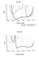
FIGS. 4A and 4B are graphs illustrating characteristics of the antenna according to the embodiment and a comparable example. -
FIGS. 5A to 5C illustrate configuration examples when the length of the bottom plate part is changed. -
FIG. 6 is a graph illustrating characteristics when the length of the bottom plate part is changed. -
FIGS. 7A to 7D illustrate configuration examples when positional relation between the meander shape part and the bottom plate part is changed. -
FIG. 8 is a graph illustrating characteristics when the positional relation between the meander shape part and the bottom plate part is changed. -
FIGS. 9A to 9E illustrates modified examples of shapes of the antenna according to the embodiment. -
FIGS. 10A to 10C illustrates a modified example in which an amplifier circuit is provided. - According to one aspect of the present invention, there is provided an antenna comprising: a first element including: a first feeding end part, a first parallel transmission line part arranged to extend from the first feeding end part along a main axis direction of the antenna, and a feeder part extending from an end part of the first parallel transmission line part, opposite to the first feeding end part, to a direction opposite to the first feeding end part; a second element including: a second feeding end part, a second parallel transmission line part arranged to extend from the second feeding end part in parallel with the first parallel transmission line part, and a folded shape part folded at an end part of the second parallel transmission line part, opposite to the second feeding end part, and extending along the main axis direction; and a bottomplate part set to a ground potential, wherein the folded shape part is electrically connected to the bottom plate part via the second parallel transmission line part and the second feeding end part, and wherein the folded shape part includes at least a part of meander shape or helical shape.
- The above antenna includes a first element, a second element and a bottomplate part. The first element includes a first feeding end part, a first parallel transmission line part and a feeder part. The second element includes a second feeding end part, a second parallel transmission line part and a folded shape part. The second feeding end part is electrically connected to the bottom plate part set to the ground potential. By arranging the first and the second parallel transmission line parts in parallel with each other, the broad-band characteristic can be achieved. By forming a meander shape or a helical shape at the folded shape part, the entire size of the antenna can be small.
- In one mode of the above antenna, the part of meander shape or the helical shape is arranged close to the bottom plate part so that the folded shape part is electromagnetically coupled to the bottomplate part. Thereby, the lower limit of the operational range of the antenna can be extended, and further downsizing becomes possible. Also, by that result, the operational range of the antenna can be adjusted according to a desired range.
- In another mode of the above antenna, the electrical length of the folded shape part is longer than the electrical length of the feeder part. Thereby, lowering of real-part of input impedance caused by the downsizing can be avoided, and it becomes easy to achieve impedance matching with the electric circuit part at the feeding end part. As a result, it becomes possible to ensure good impedance matching state over broad band.
- In still another mode of the above antenna, the feeder part includes at least one folded shape part. In still another mode of the above antenna, the feeder part includes a part of meander shape or helical shape. Thereby, the overall length of the antenna can be further shortened.
- Still another mode of the above antenna further comprises a dielectric substrate, wherein the first element and the second element are arranged on one side of the dielectric substrate, wherein the bottom plate part is arranged on the other side of the dielectric substrate, and wherein the second feeding end part and the bottom plate part are electrically connected via a through hole formed on the dielectric substrate.
- Still another mode of the above antenna further comprises a circuit unit connected to the first element and the second element, wherein the ground wiring of the circuit unit is electrically connected to the bottom plate part. In this mode, the circuit unit is provided, to which signals transmitted and received by the antenna are supplied. The bottom plate part set to the ground potential also has a role of a ground substrate for the circuit unit. Thereby, it is unnecessary to provide a ground substrate for the circuit unit separately from the bottom plate part of the antenna. Thus, the size of the antenna including the circuit unit can be small, and the configuration can be simplified.
- Preferred embodiments of the present invention will be described below with reference to the attached drawings.
-
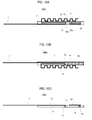
FIGS. 1A to 1C illustrate a configuration of anantenna 100 according to an embodiment of the present invention.FIG. 1A is a plane view illustrating a front side of anantenna 100, andFIG. 1B is a rear view illustrating a back side of theantenna 100.FIG. 1C is a sectional view of theantenna 100 cut at the position of a throughhole 5a described later. - As illustrated, the
antenna 100 includes anelement 1, anelement 2, adielectric substrate 5 and abottom plate part 6. Theelement 1, theelement 2 and thebottom plate part 6 correspond to antenna elements. - The
element 1 is a single linear conductor and is arranged along a main axis direction X which is the longitudinal direction of the antenna. Theelement 1 is formed with a feedingend part 1t at its one end. A part of a predetermined length of theelement 1 from the feedingend part 1t forms a paralleltransmission line part 1b. A part of theelement 1 on the tip side of the paralleltransmission line part 1b, e.g., a part extending opposite to the feedingend part 1t forms afeeder part 1a. A part of theelement 1 on the side of the feedingend part 1t is arranged on thedielectric substrate 5. - The
element 2 is formed with a feedingend part 2t at its one end. The feedingend part 2t is arranged close the feedingend part 1t of theelement 1. A part of a predetermined length of theelement 2 from the feedingend part 2t forms a paralleltransmission line part 2b. The paralleltransmission line part 2b of theelement 2 is substantially as long as the paralleltransmission line part 1b of theelement 1, and is arranged on thedielectric substrate 5 in parallel with the paralleltransmission line part 1b of theelement 1. In other words, theelement 1 and theelement 2 are arranged such that their parts of the predetermined length on the side of the feedingend parts transmission line parts - The
element 2 is turned twice, at the end position of the paralleltransmission line part 2b opposite to the feedingend part 2t, to be folded back by 180 degrees along the main axis direction X. The part thus folded forms a foldedshape part 2a. Namely, the foldedshape part 2a is substantially parallel with the paralleltransmission line parts feeder part 1a of theelement 1 extends. Also, the foldedshape part 2a has a meander shape in which plane convex-concave shapes are repeatedly formed as illustrated. While the whole part of the foldedshape part 2a is formed into the meander shape in the example ofFIGS. 1A and 1B , only a part of the foldedshape part 2a may be formed into the meander shape. - The
dielectric substrate 5 may be formed of base material for a printed wiring board, such as FR4. Thedielectric substrate 5 has a rectangular flat plate shape, and theelements FIG. 1A . - As illustrated in
FIG. 1B , thebottomplate part 6 is provided on the back-side surface of thedielectric substrate 5. Thebottom plate part 6 is formed of conductive material such as metal. Thebottom plate part 6 is electrically connected to the feedingend part 2t of theelement 2. Specifically, as illustrated inFIGS. 1A and 1C , thedielectric substrate 5 is provided with a throughhole 5a at the position of the feedingend part 2t of theelement 2, and the feedingend part 2t and thebottom plate part 6 are electrically connected via the conductive material provided inside the throughhole 5a. - In the configuration of the
above antenna 100, theelement 1 corresponds to the first element of the present invention, the feedingend part 1t corresponds to the first feeding end part, and the paralleltransmission line part 1b corresponds to the first parallel transmission line part. Also, theelement 2 corresponds to the second element of the present invention, the feedingend part 2t corresponds to the second feeding end part, and the paralleltransmission line part 2b corresponds to the second parallel transmission line part. -
FIG. 2A schematically illustrates an electric connection state of theantenna 100. Transmission/reception signals flow through thecoaxial cable 11. Itssignal line 11s is electrically connected to theelement 1, and its outer conductor (hereinafter referred to as "ground (GND) line") 11g is electrically connected to theelement 2 and thebottom plate part 6. Thereby, theelement 1 is set to the signal potential, and theelement 2 and thebottom plate part 6 are set to the ground potential. It is noted thatFIG. 2A schematically illustrates the electrical connection state of theantenna 100. In practice, the signal line of the coaxial cable is connected to the feedingend part 1t of theelement 1, and the ground line is connected to the feedingend part 2t of theelement 2. The signal line and the ground line may be connected to the feedingend parts end part 2t of theelement 2 is electrically connected to thebottom plate part 6 via the throughhole 5a as described above, theelement 2 and thebottom plate part 6 are set to the ground potential. -
FIG. 2B illustrates an example of dimensions of each parts of theantenna 100. This is the example for the case where theantenna 100 of the present invention is configured to receive the terrestrial digital broadcasting. In this example, the overall length of theantenna 100 is 233.5mm, and the width of theelements transmission line parts element 1 is 180mm. The length of the foldedshape part 2a except for the meandering amount of the meander shape part is 106mm, and the number of the meander steps is six. The length of thebottom plate part 6 is 56mm. Considering the meandering amount of the meander shape part, the electrical length of the foldedshape part 2a is longer than the electrical length of thefeeder part 1a. The antenna of the present invention may be used for the purpose other than the reception of the terrestrial digital broadcasting, and the dimension of each part of the antenna in that case is appropriately determined basically based on the frequency band of the signals to be transmitted and received. -
FIG. 3A illustrates an example of a configuration when theantenna 100 is actually mounted on a vehicle. For example, theantenna 100 is attached to the vehicle in such a state that it is put in acasing 8 of insulator.FIG. 3A illustrates an example in which the above-describedantenna 100 is put in thecasing 8 as it is, and theelement 1, theelement 2 and thedielectric substrate 5 are fixed to the predetermined positions inside thecasing 8, respectively. InFIG. 3A , for the convenience of illustration, thecasing 8 is formed of transparent resin so that the inside of thecasing 8 can be seen through. Thebottomplate part 6 provided on the back side of thedielectric substrate 5 is omitted from the illustration. -
FIG. 3B illustrates another example of the configuration when theantenna 100 is actually mounted on a vehicle. In this example, a largedielectric substrate 5x is used instead of thedielectric substrate 5 shown inFIGS. 1A to 1C . Namely, thedielectric substrate 5x is also used as a base material of theantenna 100. Theelements dielectric substrate 5x, and thebottom plate part 6 is arranged on the back-side surface of thedielectric substrate 5x. InFIG. 3B , for the convenience of the illustration, thedielectric substrate 5x is formed transparent so that thebottom plate part 6 formed on the back side can be seen through from the front side. Via the throughhole 5a provided on thedielectric substrate 5x, the feedingend part 2t of theelement 2 and thebottom plate part 6 are electrically connected. In this case, the outside of thedielectric substrate 5x is entirely covered by an insulated protection casing, so that theelement 1, theelement 2 and thebottom plate part 6 are not exposed. - It is noted that
FIGS. 3A and 3B illustrate mere examples of the configuration for actually mounting theantenna 100, and mounting manner of the antenna of the present invention is not limited to them. - Next, the characteristic feature of the
antenna 100 will be described. First, theantenna 100 basically realizes the broad-band transmission by providing theelements transmission line parts - Additionally, by positioning a part of the folded
shape part 2a close to thebottom plate part 6, the meander shape part of the foldedshape part 2a and thebottom plate part 6 are electromagnetically coupled in a good condition. Thereby, the lower limit of the operational band of the antenna is extended, and good impedance matching state is ensured for broad band. - This will be described with reference to
FIGS. 4A and 4B. FIG. 4A illustrates voltage standing wave ratio (VSWR) characteristics of theantenna 100 according to this embodiment and theantenna 100 from which thebottom plate part 6 is removed. The solid line graph C1 illustrates the VSWR characteristic of theantenna 100 according to this embodiment, e.g., the antenna having thebottomplate part 6. The broken line graph C2 illustrates the VSWR characteristic when thebottom plate part 6 is removed. Generally, it can be considered to be good impedance matching state if the VSWR value is equal to or smaller than "3". As shown by the graph C1, theantenna 100 shows a good characteristic in which the VSWR value is equal to or smaller than "3" within the 300MHz band width from 510 MHz to 810 MHz. In contrast, as shown by the broken line graph C2, if thebottom plate part 6 is removed, the impedance matching state is deteriorated over broad band, and there occurs specific points at which the matching state is extremely bad. Thus, in theantenna 100 according to this embodiment, the stable VSWR characteristic is realized for broad band by arranging the foldedshape part 2a and thebottom plate part 6 sufficiently close to each other so that they can be electromagnetically coupled. - Further, by forming the meander shape at the folded
shape part 2a, the overall length of the antenna is downsized. Still further, by forming the meander shape part at the foldedshape part 2a, the operational frequency range is adjusted. A graph C3 inFIG. 4B illustrates the VSWR characteristic of the antenna in which the foldedshape part 2a is not formed with the meander shape but is formed in a linear shape . Asisunderstoodwhencompared with the solid graph C1 inFIG. 4A , if the meander shape is not formed at the foldedshape part 2a, the operational frequency range entirely shifts to the high frequency side on the frequency axis. In such a case, in order to return the operational frequency range to the low frequency side without forming the meander shape, it is necessary to make the length of thefeeder part 1a of theelement 1 or thebottom plate part 6 longer. As a result, the overall length of the antenna increases, and the antenna becomes large in size. In this respect, according to this embodiment, by forming the meander shape at the foldedshape part 2a, the antenna can be small in size and the operational frequency range can be adjusted to be a desired frequency range. - Next, the description will be given of the length of the
bottom plate part 6 in the main axis direction X.FIGS. 5A to 5C illustrate examples in which the length of thebottom plate part 6 is changed.FIGS. 5A to 5C are rear views of theantenna 100 observed from its backside, i.e., from the side that thebottom plate part 6 is provided. Specifically, thebottom plate part 6 is extended, along the main axis direction X, to the direction opposite to thefeeder part 1a of theelement 1.FIG. 5A shows an example in which the length of thebottom plate part 6 in the main axis direction X is 56mm, similarly to theantenna 100 shown inFIGS. 1A to 1C .FIG. 5B shows an example in which the length of thebottom plate part 6 is 76mm, andFIG. 5C shows an example in which the length of thebottom plate part 6 is 96mm. InFIGS. 5B and 5C , since thebottom plate part 6 is extended, thedielectric substrate 5 is also extended in the main axis direction X. However, the shapes and the dimensions of theelements -
FIG. 6 illustrates the VSWR characteristics when the length of thebottom plate part 6 is changed in this manner. A graph C4 illustrates the VSWR characteristic when the length of thebottom plate part 6 is 56mm as shown inFIG. 5A . A graph C5 illustrates the VSWR characteristic when the length of thebottom plate part 6 is 76mm as shown inFIG. 5B . A graph C6 illustrates the VSWR characteristic when the length of thebottom plate part 6 is 96mm as shown inFIG. 5C . As is understood from each graph, by making thebottom plate part 6 longer, the lower limit of the operational range can be extended to the low frequency side. Namely, according to the antenna of this embodiment, by adjusting the length of thebottom plate part 6, the lower limit of the operational range may be set to a desired frequency. Although it is known that the lower limit of the operational range can be adjusted by changing the length of the feeder part in a conventional monopole antenna, the lower limit of the operational range can be adjusted also by the length of thebottomplate part 6 in this embodiment. Particularly, the antenna of this embodiment considers the use in which downsizing is desired. Therefore, it is extremely advantageous that the design for satisfying the desired operational range can be made by using two parameters, i.e., the length of the feeder part and the length of the bottom plate part, because it makes the design easy and it increases the freedom for the shape of the product. - Next, the description will be given of the positional relation between the meander shape part of the folded
shape part 2a and thebottom plate part 6. Now, two-step meander shape is formed and its position is moved relatively to thebottom plate part 6. The length of the foldedshape part 2a is fixed to 106mm. - Configuration examples of this case are illustrated in
FIGS. 7A to 7D . AlthoughFIGS. 7A to 7D show the plane view observed from the front side of the antenna, thebottom plate part 6 provided on the back side of the antenna is also illustrated for the convenience of explanation. Specifically,FIG. 7A illustrates theantenna 100a in which the meander shape part is arranged apart from thebottom plate part 6.FIG. 7B illustrates theantenna 100b in which the meander shape part and thebottom plate part 6 are arranged close to each other under the condition that the meander shape part and thebottom plate part 6 do not align with each other in the direction perpendicular to the main axis direction X.FIG. 7C illustrates theantenna 100c in which the meander shape part and thebottom plate part 6 are arranged such that only the first step of the meander shape part aligns with thebottom plate part 6 in the direction perpendicular to the main axis direction X.FIG. 7D illustrates theantenna 100d in which the meander shape part and thebottom plate part 6 are arranged such that both two steps of the meander shape part align with thebottom plate part 6 in the direction perpendicular to the main axis direction X. -
FIG. 8 illustrates the VSWR characteristics of theantennas 100a to 100d. As is understood by comparing the VSWR characteristic of each antenna, when the meander shape part and thebottom plate part 6 are closely arranged such that they align with each other in the direction perpendicular to the main axis direction X, the meander shape part and thebottom plate part 6 are electromagnetically coupled, and the lower limit of the operational range can be extended to the low frequency side. Therefore, by adjusting the arrangement of the meander shape part and thebottom plate part 6 to adjust the electromagnetic coupling force between them, the operational range of the antenna canbe adjusted. Thereby, the design freedom in whole antenna may be increased. - In the above example, by changing the relative position of the meander shape part and the
bottom plate part 6, the electromagnetic coupling force between them is changed. However, instead of this, similar adjustment can be done by changing the interval (gap) between the meander shape part and thebottom plate part 6. For example, in the example ofFIG. 7D , the position of the meander shape part in the main axis direction X is fixed, and the foldedshape part 2a is moved to the direction (the direction of the arrow Y inFIG. 7D ) perpendicular to the main axis direction X to increase the interval between the meander shape part and thebottom plate part 6. In this case, the smaller the interval between the meander shape part and thebottom plate part 6 is, the larger the electromagnetic coupling force between the meander shape part and thebottom plate part 6 becomes, and thereby the lower limit of the operational range is extended to the low frequency side. Conversely, the larger the interval between the meander shape part and thebottom plate part 6 is, the smaller the electromagnetic coupling force between the meander shape part and thebottom plate part 6 becomes, and thereby the lower limit of the operational range moves to the high frequency side. Therefore, the operational range can be adjusted by the adjustment of the interval between the meander shape part and thebottom plate part 6, instead of or in addition to the adjustment of the relative positional relation between the meander shape part and thebottom plate part 6 in the main axis direction X shown inFIGS. 7A to 7D . Thus, the design freedom can be further improved. - Next, various modified examples of the
antenna 100 will be described.FIGS. 9A to 9E illustrate modified examples of the shape of theantenna 100. - The
antenna 100e shown inFIG. 9A is an example in which the end part of thefeeder part 1a of theelement 1, on the side opposite to the feedingend part 1t, is folded. Theantenna 100f shown inFIG. 9B is an example in which the tip of thefeeder part 1a of theantenna 100e shown inFIG. 9A is further formed into the meander shape. Theantenna 100g shown inFIG. 9C is an example in which thefeeder part 1a of theelement 1 is formed into the meander shape. Theantenna 100h shown inFIG. 9D is an example in which the tip of thefeeder part 1a of theelement 1 is turned once in the perpendicular direction and then the turned part is formed into the meander shape. In these examples, by reducing the length of thefeeder part 1a, the overall length of the antenna can be short. - The
antenna 100i shown inFIG. 9E is an example in which a helical shape is formed, instead of the meander shape, at the foldedshape part 2a. AlthoughFIG. 9E illustrates in a plane view, the helical shape is formed as a three-dimensional loop shape like a coil. Also by the helical shape, the overall length of theelement 2 can be short, similarly to the meander shape. In addition, by arranging the helical shape part close to thebottom plate part 6, they can be electromagnetically coupled, and the operational range can be adjusted. - Next, the description will be given of an example in which the antenna is provided with an amplifier circuit.
FIG. 10A is a plane view illustrating the front side of theantenna 100x having an amplifier circuit.FIG. 10B is a rear view illustrating the back side of theantenna 100x.FIG. 10C is a sectional view of theantenna 100x, cut by the section passing through the throughhole 5a. - As illustrated, the
amplifier circuit 20 is provided on the front side of thedielectric substrate 5. Theamplifier circuit 20 is arranged close to the feedingend parts antenna 100x, and has a role of amplifying (boosting) the signal received by theantenna 100x. Thesignal line 20s of theamplifier circuit 20 is connected to the feedingend part 1t of theelement 1, and theground line 20g of theamplifier circuit 20 is connected to the feedingend part 2t of theelement 2. The signal amplified by theamplifier circuit 20 is supplied to a signal processing circuit or the like via a cable not shown. - As illustrated in
FIGS. 10B and 10C , thedielectric substrate 5 is formed with a throughhole 5b at the position under theamplifier circuit 20. A ground wiring of the amplifier circuit 20 (not shown) is electrically connected to thebottom plate part 6 via the conductor provided inside the throughhole 5b. Namely, thebottom plate part 6 functions as an antenna element set to the ground potential, and also functions as the ground substrate of theamplifier circuit 20. Thereby, the ground potential of the antenna and theamplifier circuit 20 can be common, and it becomes unnecessary to provide a ground substrate for theamplifier circuit 20 separately from thebottom plate part 6 providing the groundpotential of the antenna. Thus, the antenna can be downsized in its entirety. In the above example, for the convenience of illustration, one throughhole 5b is provided. However, in practice, it is preferred that plural throughholes 5b are provided to electrically connect the ground wiring of theamplifier circuit 20 to thebottom plate part 6. - In the above example, the
amplifier circuit 20 for amplifying the received signal is provided. Instead, an electric circuit for performing other processing such as signal processing may be provided, and an electric circuit having both the amplifying function of the received signal and other function may be provided. In any case, by connecting the ground wiring of the electric circuit to the bottom plate part of the antenna, the ground of the antenna and the electric circuit can be common, and the antenna can be downsized. - This invention can be used as a small antenna to be mounted on a portable equipment. Particularly, this invention can be preferably used as a terrestrial digital broadcasting receiving antenna attached to the front glass of an automobile, and a terrestrial digital broadcasting receiving antenna for a small portable equipment such as a portable TV and a portable game machine.
-
- 1, 2
- Element
- 1a
- Feeder part
- 1b, 2b
- Parallel transmission line part
- 1t, 2t
- Feeding end part
- 2a
- Folded shape part
- 5
- Dielectric substrate
- 5a, 5b
- Through hole
- 6
- Bottom plate part
- 11
- Coaxial cable
- 20
- Amplifier circuit
- 100, 100a - 100i
- Antenna
Claims (7)
- An antenna comprising:a first element including: a first feeding end part, a first parallel transmission line part arranged to extend from the first feeding end part along a main axis direction of the antenna, and a feeder part extending from an end part of the first parallel transmission line part, opposite to the first feeding end part, to a direction opposite to the first feeding end part;a second element including: a second feeding end part, a second parallel transmission line part arranged to extend from the second feeding end part in parallel with the first parallel transmission line part, and a folded shape part folded at an end part of the second parallel transmission line part, opposite to the second feeding end part, and extending along the main axis direction; anda bottom plate part set to a ground potential,wherein the folded shape part is electrically connected to the bottom plate part via the second parallel transmission line part and the second feeding end part, andwherein the folded shape part includes at least a part of meander shape or helical shape.
- The antenna according to claim 1, wherein the part of meander shape or the helical shape is arranged close to the bottom plate part so that the folded shape part is electromagnetically coupled to the bottom plate part.
- The antenna according to claim 1 or 2, the electrical length of the folded shape part is longer than the electrical length of the feeder part.
- The antenna according to any one of claims 1 to 3, wherein the feeder part includes at least one folded shape part.
- The antenna according to any one of claims 1 to 4, wherein the feeder part includes a part of meander shape or helical shape.
- The antenna according to any one of claims 1 to 5, further comprising a dielectric substrate,
wherein the first element and the second element are arranged on one side of the dielectric substrate,
wherein the bottom plate part is arranged on the other side of the dielectric substrate, and
wherein the second feeding end part and the bottom plate part are electrically connected via a through hole formed on the dielectric substrate. - The antenna according to any one of claims 1 to 6, further comprising a circuit unit connected to the first element and the second element,
wherein the ground wiring of the circuit unit is electrically connected to the bottom plate part.
Applications Claiming Priority (2)
| Application Number | Priority Date | Filing Date | Title |
|---|---|---|---|
| JP2010055125A JP5461248B2 (en) | 2010-03-11 | 2010-03-11 | antenna |
| PCT/JP2011/051628 WO2011111432A1 (en) | 2010-03-11 | 2011-01-27 | Antenna |
Publications (1)
| Publication Number | Publication Date |
|---|---|
| EP2546929A1 true EP2546929A1 (en) | 2013-01-16 |
Family
ID=44563261
Family Applications (1)
| Application Number | Title | Priority Date | Filing Date |
|---|---|---|---|
| EP11753094A Withdrawn EP2546929A1 (en) | 2010-03-11 | 2011-01-27 | Antenna |
Country Status (3)
| Country | Link |
|---|---|
| EP (1) | EP2546929A1 (en) |
| JP (1) | JP5461248B2 (en) |
| WO (1) | WO2011111432A1 (en) |
Families Citing this family (1)
| Publication number | Priority date | Publication date | Assignee | Title |
|---|---|---|---|---|
| CN111656609B (en) * | 2018-01-31 | 2024-03-08 | 松下知识产权经营株式会社 | Antenna device |
Family Cites Families (5)
| Publication number | Priority date | Publication date | Assignee | Title |
|---|---|---|---|---|
| JP2581834B2 (en) * | 1990-09-12 | 1997-02-12 | 三菱電機株式会社 | Antenna device |
| JP3111824B2 (en) * | 1994-08-31 | 2000-11-27 | 三菱電機株式会社 | Plate antenna for mobile phone and method of manufacturing the same |
| JPH10107533A (en) * | 1996-10-02 | 1998-04-24 | Toa Corp | Antenna |
| JP4858971B2 (en) * | 2006-12-14 | 2012-01-18 | 株式会社ヨコオ | Broadband loop antenna |
| JP2009218872A (en) * | 2008-03-11 | 2009-09-24 | Panasonic Corp | Active antenna device, and diversity reception system or portable radio communication device using the same |
-
2010
- 2010-03-11 JP JP2010055125A patent/JP5461248B2/en not_active Expired - Fee Related
-
2011
- 2011-01-27 EP EP11753094A patent/EP2546929A1/en not_active Withdrawn
- 2011-01-27 WO PCT/JP2011/051628 patent/WO2011111432A1/en not_active Ceased
Non-Patent Citations (1)
| Title |
|---|
| See references of WO2011111432A1 * |
Also Published As
| Publication number | Publication date |
|---|---|
| JP2011193060A (en) | 2011-09-29 |
| JP5461248B2 (en) | 2014-04-02 |
| WO2011111432A1 (en) | 2011-09-15 |
Similar Documents
| Publication | Publication Date | Title |
|---|---|---|
| US7289069B2 (en) | Wireless device antenna | |
| TWI419411B (en) | Asymmetric dipole antenna | |
| US7053841B2 (en) | Parasitic element and PIFA antenna structure | |
| US7248224B2 (en) | Antenna device having radiation characteristics suitable for ultrawideband communications | |
| CN107453028B (en) | Connector for film antenna to FAKRA | |
| JPWO2004109857A1 (en) | Antenna and electronic equipment using it | |
| KR102168317B1 (en) | Mobile terminal and antenna radiation method of mobile terminal | |
| CN101651254B (en) | Surface Mounted Panel Antenna | |
| JP5969821B2 (en) | Antenna device | |
| EP2495808A1 (en) | Multiband antenna | |
| EP2993731A1 (en) | Antenna assembly and electronic device comprising said antenna assembly | |
| EP3032645A1 (en) | An assembly of circuit boards and electronic device comprising said assembly | |
| JPWO2004097980A1 (en) | Broadband flat antenna | |
| CN100578859C (en) | Antenna devices and electronic equipment | |
| WO2010090573A1 (en) | Antenna | |
| EP3154125B1 (en) | Eight-frequency band antenna | |
| US9660332B2 (en) | Antenna apparatus and feeding structure thereof | |
| EP2546929A1 (en) | Antenna | |
| US20090073051A1 (en) | Flat dual-band antenna | |
| EP3154124B1 (en) | Ten-frequency band antenna | |
| EP2037532A1 (en) | Flat dual-band antenna | |
| TWI573322B (en) | Antenna assembly and wireless communication device employing same | |
| US8054230B2 (en) | Multi-band antenna | |
| US7286086B2 (en) | Gain-adjustable antenna | |
| CN102569999B (en) | Antenna |
Legal Events
| Date | Code | Title | Description |
|---|---|---|---|
| PUAI | Public reference made under article 153(3) epc to a published international application that has entered the european phase |
Free format text: ORIGINAL CODE: 0009012 |
|
| 17P | Request for examination filed |
Effective date: 20120907 |
|
| AK | Designated contracting states |
Kind code of ref document: A1 Designated state(s): AL AT BE BG CH CY CZ DE DK EE ES FI FR GB GR HR HU IE IS IT LI LT LU LV MC MK MT NL NO PL PT RO RS SE SI SK SM TR |
|
| DAX | Request for extension of the european patent (deleted) | ||
| RAP1 | Party data changed (applicant data changed or rights of an application transferred) |
Owner name: PIONEER CORPORATION |
|
| STAA | Information on the status of an ep patent application or granted ep patent |
Free format text: STATUS: THE APPLICATION HAS BEEN WITHDRAWN |
|
| 18W | Application withdrawn |
Effective date: 20141208 |