EP2546612A2 - Method for working out the angular position of a rotating element and device for carrying out such a method - Google Patents
Method for working out the angular position of a rotating element and device for carrying out such a method Download PDFInfo
- Publication number
- EP2546612A2 EP2546612A2 EP20110183313 EP11183313A EP2546612A2 EP 2546612 A2 EP2546612 A2 EP 2546612A2 EP 20110183313 EP20110183313 EP 20110183313 EP 11183313 A EP11183313 A EP 11183313A EP 2546612 A2 EP2546612 A2 EP 2546612A2
- Authority
- EP
- European Patent Office
- Prior art keywords
- light
- sensor
- rotating element
- mask
- fixed
- Prior art date
- Legal status (The legal status is an assumption and is not a legal conclusion. Google has not performed a legal analysis and makes no representation as to the accuracy of the status listed.)
- Granted
Links
Images


Classifications
-
- G—PHYSICS
- G01—MEASURING; TESTING
- G01D—MEASURING NOT SPECIALLY ADAPTED FOR A SPECIFIC VARIABLE; ARRANGEMENTS FOR MEASURING TWO OR MORE VARIABLES NOT COVERED IN A SINGLE OTHER SUBCLASS; TARIFF METERING APPARATUS; MEASURING OR TESTING NOT OTHERWISE PROVIDED FOR
- G01D5/00—Mechanical means for transferring the output of a sensing member; Means for converting the output of a sensing member to another variable where the form or nature of the sensing member does not constrain the means for converting; Transducers not specially adapted for a specific variable
- G01D5/26—Mechanical means for transferring the output of a sensing member; Means for converting the output of a sensing member to another variable where the form or nature of the sensing member does not constrain the means for converting; Transducers not specially adapted for a specific variable characterised by optical transfer means, i.e. using infrared, visible, or ultraviolet light
- G01D5/28—Mechanical means for transferring the output of a sensing member; Means for converting the output of a sensing member to another variable where the form or nature of the sensing member does not constrain the means for converting; Transducers not specially adapted for a specific variable characterised by optical transfer means, i.e. using infrared, visible, or ultraviolet light with deflection of beams of light, e.g. for direct optical indication
- G01D5/285—Mechanical means for transferring the output of a sensing member; Means for converting the output of a sensing member to another variable where the form or nature of the sensing member does not constrain the means for converting; Transducers not specially adapted for a specific variable characterised by optical transfer means, i.e. using infrared, visible, or ultraviolet light with deflection of beams of light, e.g. for direct optical indication using a movable mirror
-
- G—PHYSICS
- G01—MEASURING; TESTING
- G01D—MEASURING NOT SPECIALLY ADAPTED FOR A SPECIFIC VARIABLE; ARRANGEMENTS FOR MEASURING TWO OR MORE VARIABLES NOT COVERED IN A SINGLE OTHER SUBCLASS; TARIFF METERING APPARATUS; MEASURING OR TESTING NOT OTHERWISE PROVIDED FOR
- G01D5/00—Mechanical means for transferring the output of a sensing member; Means for converting the output of a sensing member to another variable where the form or nature of the sensing member does not constrain the means for converting; Transducers not specially adapted for a specific variable
- G01D5/26—Mechanical means for transferring the output of a sensing member; Means for converting the output of a sensing member to another variable where the form or nature of the sensing member does not constrain the means for converting; Transducers not specially adapted for a specific variable characterised by optical transfer means, i.e. using infrared, visible, or ultraviolet light
- G01D5/32—Mechanical means for transferring the output of a sensing member; Means for converting the output of a sensing member to another variable where the form or nature of the sensing member does not constrain the means for converting; Transducers not specially adapted for a specific variable characterised by optical transfer means, i.e. using infrared, visible, or ultraviolet light with attenuation or whole or partial obturation of beams of light
- G01D5/34—Mechanical means for transferring the output of a sensing member; Means for converting the output of a sensing member to another variable where the form or nature of the sensing member does not constrain the means for converting; Transducers not specially adapted for a specific variable characterised by optical transfer means, i.e. using infrared, visible, or ultraviolet light with attenuation or whole or partial obturation of beams of light the beams of light being detected by photocells
- G01D5/36—Forming the light into pulses
- G01D5/38—Forming the light into pulses by diffraction gratings
Definitions
- the present invention relates to the technical field of the determination with high precision of the angular positions of a rotational part or element, for instance a shaft, with respect to a fixed frame or structure.
- Devices such as optical encoders, such as end-of-shaft encoders, which allow such a determination, are already used for instance in the field of electric actuators or motors.
- the present invention concerns more particularly a method for determining a reliable angular position of a rotating shaft with a very high accuracy.
- the present invention concerns also a device for carrying out the above mentioned method.
- the device comprises a fixed light source emitting a beam of light in the axial direction of the shaft toward a slanted mirror which is integral in rotation with the shaft.
- the device comprises also at least one ring-shaped sensor which is concentric with the axial direction and on which the reflected light beam hits.
- an object of the present invention is to propose a new method for dermining the angular position of a rotating element, which does not present the aforementioned drawbacks.
- the object of the present invention is therefore to propose a new method for determining the angular position of a rotating element which is reliable and very precise.
- Another object of the present invention is to propose a novel device for determining the angular position of a rotating element which is reliable and very precise although presenting large positioning tolerances for its constitutive parts during their mounting.
- Another object of the present invention is to propose a novel device for determining the angular position of a rotating element which is very compact.
- Another object of the present invention is to propose a novel device for determining the angular position of a rotating element which works at very high rotation speeds, for instance higher than 500'000 rpm.
- Another object of the present invention is to propose a novel device for determining the angular position of a rotating element which is unexpensive especially in its manufacturing and mounting costs.
- Another object of the present invention is to propose a novel device for measuring the rotating quality of a rotating axis.
- the device can measure if the rotation follows a perfect circle or not.
- Another object of the present invention is to propose a novel device for diagnosing wear-out by measuring the mecanical degradation over time of a rotating element.
- a method for working out the angular position of a rotating element which is mounted in a fixed frame consisting in using at least one light source emitting a beam of light in the direction of a fixed sensor and using computing means for processing an output signal of the sensor, characterized in that it consists in:
- the method in accordance with the invention consists in using a fixed source of light and a reflection of the beam of light on a slanted and polished end of the rotating element.
- it consists in using a fixed source of light and a reflection of the beam of light on a mirror which is fixed in a tilted position with respect to the rotation axis on an end of the rotating element.
- the method in accordance with the invention consists in using two fixed sources of light emitting each a light of different color, the end of the rotating element, which faces the mask, presenting a slanted and polished surface for reflecting the two beams of light.
- the method in accordance with the invention consists in using one mobile source of light arranged in an off-centered position on a disc which is integral in rotation with the rotating element and of driving into rotation the disc in a plane parallel to the mask.
- the method in accordance with the invention consists in using two mobile sources of light emitting each a light of different color on a disc which is integral in rotation with the rotating element, the sources of light being fixed in an off-centered and diametrically opposite positions and of driving into rotation the disc in a plane parallel with the mask.
- the method consists in using an absolute code integrated in the regular two dimensional pattern, in order to identify absolute position on the mask.
- a device for carrying the above mentioned method providing the angular position of a rotating element which is able to rotate in a fixed frame, comprising at least one point-source LED kind source of light, emitting a beam of light, optical transmission means localized on the path of the beam of light and influencing the beam of light in dependence of the angular position of the rotating shaft, a sensor comprising a pixel array which is hit by the influenced beam of light and processing and computing means for providing the angular position of the rotating element by using the output signal of the sensor, characterized in that the optical transmission means comprise: a mask which presents a repetitive two dimensional pattern of transparent and opaque areas and which is arranged in a spaced and fixed position covering the sensor and which is parallel to the sensor, in order to generate on the sensor the image or shadows of the mask, and communication means for providing the processing and computing means with the output signal of the sensor in order to determine the position of the image or shadows of the mask and to compute the angular position of the
- point source of light we mean a source of light whose emitting surface is small compared to the distance which separates it from the sensor, and which has diverging light rays, that is, non-parallel light rays.
- the transparent areas of the mask are constituted for instance of perforations or holes or of a transparent material such as glass.
- the repetitive two dimensional pattern comprises an absolute code for identifying the absolute position on the mask. This allows in case that the measured points move a lot, to recognize their precise position with respect to a reference which is also integrated in said code.
- the source of light is arranged in a fixed position on the mask, aligned with the rotation axis of the rotating element and facing a slanted and polished end of the rotating element for reflecting the beam of light.
- At least one source of light is arranged in at least one fixed position in the plane of the sensor and nearby the sensor, the end of the rotating element facing the mask, presenting a slanted and polished surface for reflecting the beam of light.
- the device in accordance with the invention, it comprises two sources of light, each source of light emitting a light of different color, each source of light being arranged in a fixed an off-centered position in the plane of the sensor, nearby one side of the sensor, the end of the rotating element which faces the mask, presenting a slanted and polished surface for reflecting the two beams of light.
- the senor comprises areas covered with different optical filters in order to differentiate the images or shadows generated by the light sources.
- the sensor could comprise a filter per pixel.
- the device in accordance with the invention, it comprises two sources of light, each source of light emitting a light of different color, each source of light being arranged in a fixed an off-centered position on the mask, the end of the rotating element which faces the mask, presenting a slanted and polished surface for reflecting the two beams of light.
- the source of light is arranged in a fixed position on the mask, aligned with the rotation axis of the rotating element and facing a tilted mirror fixed on the end of the rotating element for reflecting the beam of light.
- the device in accordance with the invention, it comprises one mobile source of light, arranged in a fixed, off-centered position on a disc which is orthogonal to the rotating element, the disc being integral in rotation with the rotating element and parallel to the plane of the mask.
- the device in accordance with the invention, it comprises two sources of light, each source of light emitting a light of different color, the sources of light being arranged in fixed, off-centered and diametrically opposite positions, on a disc which is integral in rotation with the rotating element and which is parallel with the plane of the mask.
- the communication means, the computing means and the processing means are integrated in the sensor.
- Another advantage of the invention is the possibility to measure how precisely the axis is turning. Because of mechanical imperfections, for example in the ball bearings, the axis does not describe a perfect circle. Thus, by fitting a circle on a set of (x T , y T ) compensated and measuring statistically how much the measurements deviate from the fitted circle, the method can estimate the quality of the rotating device. In addition, this measurement can be repeated over time, to estimate the wear out of the rotating device. It is the possible to trigger an alarm as soon as the rotating device is wearing out too much, that it, as soon as the mean distance from the fitted circle to the measurements is above a predetermined threshold.
- An advantage of the device in accordance with the invention lies in its very large versatility.
- the device in accordance with the invention fits well with many different technical applications especially in the field of rotary encoders for end-of-shaft arrangements.
- Another advantage of the device in accordance with the invention lies in the fact that its constitutive parts can be mounted with very large mounting tolerances.
- the device in accordance with the invention lies in that it can comprise a small sized sensor.
- the photosensitive area of the sensor has for instance a surface as small as 1 mm 2 and can provide a high resolution and measurement accuracy.
- the device in accordance with the invention comprising two sources of light, provides a precise and absolute angular position without using any calibration means or when the rotation axis drifts during operation.
- the line crossing the two positions of the light sources provides the absolute angular position of the rotating element or shaft.
- the angular position of the rotating element is thus independent of the position of the axis during operation.
- Another advantage of the device in accordance with the invention lies in that the mask is fixed to the sensor, enhancing so its thermal and mechanical stability. Additionally, no imaging lens is needed, resulting in a lowering of the costs of the device. The fact that no plastic parts are needed will allow operation in a high temperature environment.
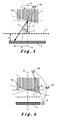
- Figure 1 illustrates a first embodiment of a device in accordance with the invention, for providing the angular position of a rotating element 1 such as a shaft, which is able to rotate in a fixed frame.
- the device comprises a point-source of light 2, which may be a Light Emitting Diode (LED), emitting a beam of light 3.
- LED Light Emitting Diode
- the device comprises also optical transmission means localized on the path of the beam of light 3 and influencing the beam of light 3 in dependence on the angular position of the rotating element 1.
- the device comprises also a sensor 4 extending in a plane which is orthogonal to the rotation axis A of the rotating element 1.
- the sensor 4 comprises a pixel array which is hit by the influenced beam of light 3.
- the device comprises also processing and computing means for providing the angular position of the rotating element 1 by using the output signal of the sensor 4.
- the optical transmission means comprise a mask 5 which presents a two dimensional repetitive pattern of transparent and opaque areas and which is arranged in a spaced and fixed position covering the sensor 4 and which is parallel to the sensor 4, in order to generate on the sensor 4, shadows forming the image of the mask 5.
- the optical transmission means comprise also communication means for providing the processing and computing means with the output signal of the sensor 4 in order to determine the position of the image or shadow of the mask 5, and to compute the angular position of the rotating element 1.
- the mask 5 extends at a distance d from the sensor 4.
- the distance d is preferably comprised in a range of 0.1 mm to 5 mm, for example 0.5 mm.
- the source of light 2 is arranged in a fixed position on the mask 5, aligned with the rotation axis A of the rotating element 1 and facing a slanted and polished end 1a of the rotating element 1 for reflecting the beam of light 3.
- the slanted and polished end 1 a presents an angle ⁇ with respect to a fictive plane P which is orthogonal to the rotation axis A.
- the fixed source of light 2 can also be represented by a corresponding mobile virtual source of light 2a, which in this case turns around the axis A.
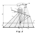
- Figure 2 illustrates a second embodiment of a device in accordance with the invention, in which the source of light 2 is arranged in a fixed position on the mask 5, aligned with the rotation axis A of the rotating element 1 and facing a tilted mirror 6 fixed on the end of the rotating element 1 for reflecting the beam of light 3.
- the mirror 6 is advantageously fixed on the slanted end 1 a of the rotating element 1.
- the mask 5 extends at a distance d1 from the sensor 4 and the virtual source of light 2a turns in a plane which is located at a distance d2 from the mask 5.
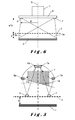
- the device comprises two sources of light 7 and 8, each source of light emitting a light of different color and being arranged in a fixed an off-centered position on the mask 5.
- the rotating element 1 faces the mask 5 with the surface of its slanted and polished end 1 a, for reflecting the two emitted beams of light.
- the fixed sources of light 7 and 8 can also be represented by mobile virtual sources of light 7a and 8a which in this case are turning in tilted planes with respect to the rotation axis A.
- the device comprises one source of light 2 which is arranged in a fixed position in the extension plane of the sensor 4 and nearby the sensor 4.
- the rotating element 1 is facing the mask 5 with its slanted and polished end 1 a for reflecting the emitted beam of light.
- the fixed source of light 2 can also be represented by a mobile virtual source of light 2a which in this case is turning during the rotation of the rotating element 1, in a tilted plane with respect to the rotation axis A.
- the device comprises two sources of light 7 and 8, each source of light 7, 8 emitting a light of different color and being arranged in a fixed an off-centered position in the plane of the sensor 4, nearby a side of the sensor 4.
- the rotating element 1 faces the mask 5, with its slanted and polished end 1 a for reflecting the two emitted beams of light.
- the device comprises two sources of light 7,8, each source of light emitting a light of different color.
- the sources of light 7 and 8 are arranged in fixed, off-centered and diametrically opposite positions on a disc 9 which is integral in rotation with the rotating element 1 and which is parallel with the plane of the mask 5.
- the two emitted beams of light 3a and 3b are directed toward the mask 5 and the sensor 4.
- the senor 4 or the mask 5 may comprise at least two areas covered each with a different optical filter, in order to differentiate the images or shadows generated by the distinct light sources and the mask 5.
- the senor 4 may comprise a color filter array, each pixel being covered with a different filter than its neighboring pixels, as it is used in a traditional color camera, in order to differentiate the images or shadows generated by the distinct light sources and the mask 5.
- the mask does not need a plurality of color filters.
- the mask 5 may be metallic with a two dimensional pattern of holes.
- the shape of each hole is for instance rectangular and its dimensions are for instance between 10 ⁇ m and 200 ⁇ m, for example 50 ⁇ m.
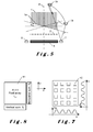
- the figure 7 is an illustration of an image of a mask 5 on the sensor 4.
- the image comprises a repetitive pattern of rectangular zones of light 10.
- the figure 8 is an illustration of an exemplary construction of the sensor 4.
- the sensor 4 comprises a pixel array 11 of m rows and n columns of pixels, on which is casted the image or shadows of the mask 5.
- the sensor 4 can so provide an output signal which depends on the angular position of the rotating element 1 by using the position of the image of the shadows.
- the figure 9 is an illustration of an example of an image illustrating successive positions of an image or shadow point on the sensor 4 of the device in accordance with the invention during rotation of the rotating element 1.
- This image is assimilated to a fitted circle 11 in a two dimensional representation.
- the measurement unit of the horizontal and vertical axis is given in micrometers.
- the position of a point of an image, for instance a shadow with coordinates x and y follows a circular or an elliptical path.
- the circular path is the fitted circle 11.
- the computation of position x from signal Sx is well known in the art.
- the figure 10 is an exemplary representation of the real positions of shadow points on the sensor 4 with respect to positions constituting the fitted circle, in dependence of the angular position of the rotating element 1.
- the measurement unit of the vertical axis corresponding to positioning errors is given in micrometers and the measurement unit of the horizontal axis corresponding to the angular position, is given in radians. It is obvious that the positioning errors are held at a very low level.
- the path followed by the virtual position of the source of light 2a is a circle for a central arrangement of the source of light 2.
- the angle ⁇ of the plane of the mirror 6 with respect to the perpendicular plane to the rotation axis A determines the virtual radius R vi of this circle.
- the effective radius R eff of the device or encoder is the radius of the circular path followed by the shadow point with coordinates x,y.
- R eff determines the parameters of the said rotary encoder such as precision and maximal rotation speed due to the motion-blur limit.
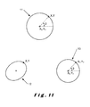
- the figure 11 is a schematic and an exemplary representation of some steps of computing the angular position ⁇ within the method in accordance with the invention.
- the method for working out the angular position ⁇ of the rotating element 1, which is mounted in a fixed structure consists in using at least one light source 2 emitting a beam of light 3 in the direction of the fixed sensor 4 and a mask 5 altering the beam of light 3.
- the method consists in computing and processing the output signal of the sensor 4.
- a step a) consists in positioning the light source with respect to the rotating element 1 and of the sensor 4 in a way so as to induce an interaction between the beam of light 3 and the sensor 4 which depends on the angular position ⁇ of the rotating element 1.
- a step b) consists in positioning on the path of the beam of light 3, in a fixed position with respect to the sensor 4, the mask 5 which presents a repetitive two dimensional pattern of transparent and opaque areas,
- a step c) consists in detecting the image generated by the mask 5 on the sensor 4.
- a step d) consists in processing the output signal of the sensor 4 for determining the position of the image or shadow on the sensor 4.
- An additional step e) consists in computing the angular position ⁇ of the rotating element by using the position of the image or shadow on the sensor 4.
- the processing and computing means are used to determine the center C of the fitted circle 11.
- This center C has the coordinates x 0 and y 0 .
- the processing and computing means calculate transformed coordinates x T and y T corresponding to the coordinates of the point on a calculated circle 13.
- ⁇ atan ⁇ y T - y 0 x T - x 0
- the device according to the invention allows to achieve the following indicated performances with the following indicated parameters:
- the method in accordance with the invention may comprise also calibration steps.
- a first calibration step consists in turning the rotating element 1 for more than one turn, with constant speed and measuring position 14 coordinates Xi , Yi and with constant sampling frequency.
- the following step consists in fitting a circle 15 and determining the coordinates X 0 , Yo of the center 16 of this circle 15.
- a second calibration step consists in determining the angular position ⁇ i corresponding to the measurements of the first step for one turn, with 1 ⁇ i ⁇ n.
- the following step consists in calculating the reference angular position B r , i for each measured point taking advantage of the constant speed turning and the constant sampling rate condition.
- n c can be integer or non-integer and is approximately equal to n, since the rotating element rotates for one turn.
- the device according to the invention can also find applications in cases where the effective radius is extended to cover a radius range in which more than one sensor 4 can be used.
- One kind of sensor 4 can so fit with a large number of different encoders.
Landscapes
- Physics & Mathematics (AREA)
- General Physics & Mathematics (AREA)
- Optical Transform (AREA)
- Length Measuring Devices By Optical Means (AREA)
Abstract
characterized in that it consists in:
- a) arranging the light source with respect to the rotating element and of the sensor in a way so as to induce an interaction between the beam of light and the sensor which depends on the angular position of the rotating shaft,
- b) arranging on the path of the beam of light, in a fixed position with respect to the sensor, a perforated mask which presents a repetitive pattern of perforations,
- c) detecting shadows generated by the mask on the sensor,
- d) processing the output signal of the sensor for determining the position of the shadows on the sensor,
- e) and computing the angular position of the rotating element by using the position of the shadows.
Description
- The present invention relates to the technical field of the determination with high precision of the angular positions of a rotational part or element, for instance a shaft, with respect to a fixed frame or structure. Devices such as optical encoders, such as end-of-shaft encoders, which allow such a determination, are already used for instance in the field of electric actuators or motors.
- The present invention concerns more particularly a method for determining a reliable angular position of a rotating shaft with a very high accuracy.
- The present invention concerns also a device for carrying out the above mentioned method.
- In an application concerning a device for determining the angular position of a rotating shaft, which is disclosed in document
DE 39 39 905 , an angular position with high resolution and/or an absolute angular position with respect to a fixed part, can be obtained. The device comprises a fixed light source emitting a beam of light in the axial direction of the shaft toward a slanted mirror which is integral in rotation with the shaft. The device comprises also at least one ring-shaped sensor which is concentric with the axial direction and on which the reflected light beam hits. - However, a main drawback of such a device is that the positioning of the sensor with respect to the axis needs to be very precise. The costs resulting of such a positioning operation, is very high. The accuracy of the measured values, which is based on the position of a sole light point, is anyway not very precise. The cost of a ring-shaped sensor or multiple sensor arrangement is also very expensive. In addition, such a device cannot be made very small.
- Consequently, an object of the present invention is to propose a new method for dermining the angular position of a rotating element, which does not present the aforementioned drawbacks.
- The object of the present invention is therefore to propose a new method for determining the angular position of a rotating element which is reliable and very precise.
- Another object of the present invention is to propose a novel device for determining the angular position of a rotating element which is reliable and very precise although presenting large positioning tolerances for its constitutive parts during their mounting.
- Another object of the present invention is to propose a novel device for determining the angular position of a rotating element which is very compact.
- Another object of the present invention is to propose a novel device for determining the angular position of a rotating element which works at very high rotation speeds, for instance higher than 500'000 rpm.
- Another object of the present invention is to propose a novel device for determining the angular position of a rotating element which is unexpensive especially in its manufacturing and mounting costs.
- Another object of the present invention is to propose a novel device for measuring the rotating quality of a rotating axis. In other words, the device can measure if the rotation follows a perfect circle or not.
- Another object of the present invention is to propose a novel device for diagnosing wear-out by measuring the mecanical degradation over time of a rotating element.
- The objects given to the invention are achieved with the help of a method for working out the angular position of a rotating element which is mounted in a fixed frame, consisting in using at least one light source emitting a beam of light in the direction of a fixed sensor and using computing means for processing an output signal of the sensor, characterized in that it consists in:
- a) positioning the light source with respect to the rotating element and of the sensor in a way so as to induce an interaction between the beam of light and the sensor which depends on the angular position of the rotating shaft,
- b) positioning on the path of the beam of light, in a fixed position with respect to the sensor, a mask which presents a repetitive two dimensional pattern of transparent and opaque areas,
- c) detecting the image or shadows generated by the mask on the sensor,
- d) processing the output signal of the sensor for determining the position of the image or shadows on the sensor,
- e) and computing the angular position of the rotating element by using the position of the image or shadows on the sensor.
- In an example of carrying out the method in accordance with the invention, it consists in using a fixed source of light and a reflection of the beam of light on a slanted and polished end of the rotating element.
- In another example of carrying out the method in accordance with the invention, it consists in using a fixed source of light and a reflection of the beam of light on a mirror which is fixed in a tilted position with respect to the rotation axis on an end of the rotating element.
- In another example of carrying out the method in accordance with the invention, it consists in using two fixed sources of light emitting each a light of different color, the end of the rotating element, which faces the mask, presenting a slanted and polished surface for reflecting the two beams of light.
- In another example of carrying out the method in accordance with the invention, it consists in using one mobile source of light arranged in an off-centered position on a disc which is integral in rotation with the rotating element and of driving into rotation the disc in a plane parallel to the mask.
- In another example of carrying out the method in accordance with the invention, it consists in using two mobile sources of light emitting each a light of different color on a disc which is integral in rotation with the rotating element, the sources of light being fixed in an off-centered and diametrically opposite positions and of driving into rotation the disc in a plane parallel with the mask.
- In an implementation in accordance with the invention, the method consists in using an absolute code integrated in the regular two dimensional pattern, in order to identify absolute position on the mask.
- The objects given to the invention are also achieved with the help of a device for carrying the above mentioned method, providing the angular position of a rotating element which is able to rotate in a fixed frame, comprising at least one point-source LED kind source of light, emitting a beam of light, optical transmission means localized on the path of the beam of light and influencing the beam of light in dependence of the angular position of the rotating shaft, a sensor comprising a pixel array which is hit by the influenced beam of light and processing and computing means for providing the angular position of the rotating element by using the output signal of the sensor, characterized in that the optical transmission means comprise: a mask which presents a repetitive two dimensional pattern of transparent and opaque areas and which is arranged in a spaced and fixed position covering the sensor and which is parallel to the sensor, in order to generate on the sensor the image or shadows of the mask, and communication means for providing the processing and computing means with the output signal of the sensor in order to determine the position of the image or shadows of the mask and to compute the angular position of the rotating element.
- By point source of light, we mean a source of light whose emitting surface is small compared to the distance which separates it from the sensor, and which has diverging light rays, that is, non-parallel light rays.
- The transparent areas of the mask are constituted for instance of perforations or holes or of a transparent material such as glass.
- In an embodiment of the device in accordance with the invention, the repetitive two dimensional pattern comprises an absolute code for identifying the absolute position on the mask. This allows in case that the measured points move a lot, to recognize their precise position with respect to a reference which is also integrated in said code.
- In an embodiment of the device in accordance with the invention, the source of light is arranged in a fixed position on the mask, aligned with the rotation axis of the rotating element and facing a slanted and polished end of the rotating element for reflecting the beam of light.
- In an embodiment of the device in accordance with the invention, at least one source of light is arranged in at least one fixed position in the plane of the sensor and nearby the sensor, the end of the rotating element facing the mask, presenting a slanted and polished surface for reflecting the beam of light.
- In an embodiment of the device in accordance with the invention, it comprises two sources of light, each source of light emitting a light of different color, each source of light being arranged in a fixed an off-centered position in the plane of the sensor, nearby one side of the sensor, the end of the rotating element which faces the mask, presenting a slanted and polished surface for reflecting the two beams of light.
- In an embodiment using two light sources of different colors, the sensor comprises areas covered with different optical filters in order to differentiate the images or shadows generated by the light sources. Alternatively, the sensor could comprise a filter per pixel.
- In an embodiment of the device in accordance with the invention, it comprises two sources of light, each source of light emitting a light of different color, each source of light being arranged in a fixed an off-centered position on the mask, the end of the rotating element which faces the mask, presenting a slanted and polished surface for reflecting the two beams of light.
- In an embodiment of the device in accordance with the invention, the source of light is arranged in a fixed position on the mask, aligned with the rotation axis of the rotating element and facing a tilted mirror fixed on the end of the rotating element for reflecting the beam of light.
- In an embodiment of the device in accordance with the invention, it comprises one mobile source of light, arranged in a fixed, off-centered position on a disc which is orthogonal to the rotating element, the disc being integral in rotation with the rotating element and parallel to the plane of the mask.
- In another embodiment of the device in accordance with the invention, it comprises two sources of light, each source of light emitting a light of different color, the sources of light being arranged in fixed, off-centered and diametrically opposite positions, on a disc which is integral in rotation with the rotating element and which is parallel with the plane of the mask.
- In an embodiment of the device in accordance with the invention, the communication means, the computing means and the processing means are integrated in the sensor.
- Another advantage of the invention is the possibility to measure how precisely the axis is turning. Because of mechanical imperfections, for example in the ball bearings, the axis does not describe a perfect circle. Thus, by fitting a circle on a set of (xT, yT) compensated and measuring statistically how much the measurements deviate from the fitted circle, the method can estimate the quality of the rotating device. In addition, this measurement can be repeated over time, to estimate the wear out of the rotating device. It is the possible to trigger an alarm as soon as the rotating device is wearing out too much, that it, as soon as the mean distance from the fitted circle to the measurements is above a predetermined threshold.
- An advantage of the device in accordance with the invention lies in its very large versatility. The device in accordance with the invention fits well with many different technical applications especially in the field of rotary encoders for end-of-shaft arrangements.
- Another advantage of the device in accordance with the invention lies in the fact that its constitutive parts can be mounted with very large mounting tolerances.
- Another advantage of the device in accordance with the invention lies in that it can comprise a small sized sensor. The photosensitive area of the sensor has for instance a surface as small as 1 mm2 and can provide a high resolution and measurement accuracy.
- The device in accordance with the invention comprising two sources of light, provides a precise and absolute angular position without using any calibration means or when the rotation axis drifts during operation. The line crossing the two positions of the light sources provides the absolute angular position of the rotating element or shaft. The angular position of the rotating element is thus independent of the position of the axis during operation.
- Another advantage of the device in accordance with the invention lies in that the mask is fixed to the sensor, enhancing so its thermal and mechanical stability. Additionally, no imaging lens is needed, resulting in a lowering of the costs of the device. The fact that no plastic parts are needed will allow operation in a high temperature environment.
- The invention and its advantages also appear in greater detail from the following description of an embodiment given by way of illustration and with reference to the accompanying figures in which:
-
figure 1 is a schematic illustration of a first embodiment of a device in accordance with the invention, -
figure 2 is a schematic illustration of a second embodiment of a device in accordance with the invention, -
figure 3 is a schematic illustration of a third embodiment of a device in accordance with the invention, -
figure 4 is a schematic illustration of a fourth embodiment of a device in accordance with the invention, -
figure 5 is a schematic illustration of a fifth embodiment of a device in accordance with the invention, -
figure 6 is a schematic illustration of a sixth embodiment of a device in accordance with the invention, -
figure 7 is an illustration of an example of an image of a mask in an embodiment of the device in accordance with the invention, -
figure 8 is an illustration of an example of a pixel array which is used for providing an output signal of the sensor in a device in accordance with the invention, -
figure 9 is a exemplary representation of an example of an image illustrating successive positions of a shadow point on a sensor of the device in accordance with the invention, -
figure 10 is an exemplary representation of an error of positioning of shadow points with respect to a computed positions, in dependence of the angular position, in a device in accordance with the invention, -
figure 11 is a schematic illustration of the steps of computing the angular position within the method in accordance with the invention, -
figure 12 is an illustration of a fitted circle used in calibration steps in the frame of the method in accordance with the invention, - and
figure 13 illustrates an example of a polynomial fitted representation of the angular error with respect to the angular position used in the calibration steps in the frame of the method in accordance with the invention. - Elements that are structurally and functionally identical, and that are present in more than one distinct figure or illustration, are given the same numeric or alphanumeric reference in each of them.
-
Figure 1 illustrates a first embodiment of a device in accordance with the invention, for providing the angular position of arotating element 1 such as a shaft, which is able to rotate in a fixed frame. The device comprises a point-source oflight 2, which may be a Light Emitting Diode (LED), emitting a beam oflight 3. - The device comprises also optical transmission means localized on the path of the beam of
light 3 and influencing the beam oflight 3 in dependence on the angular position of therotating element 1. - The device comprises also a
sensor 4 extending in a plane which is orthogonal to the rotation axis A of therotating element 1. Thesensor 4 comprises a pixel array which is hit by the influenced beam oflight 3. - The device comprises also processing and computing means for providing the angular position of the
rotating element 1 by using the output signal of thesensor 4. - The optical transmission means comprise a
mask 5 which presents a two dimensional repetitive pattern of transparent and opaque areas and which is arranged in a spaced and fixed position covering thesensor 4 and which is parallel to thesensor 4, in order to generate on thesensor 4, shadows forming the image of themask 5. - The optical transmission means comprise also communication means for providing the processing and computing means with the output signal of the
sensor 4 in order to determine the position of the image or shadow of themask 5, and to compute the angular position of therotating element 1. Themask 5 extends at a distance d from thesensor 4. The distance d is preferably comprised in a range of 0.1 mm to 5 mm, for example 0.5 mm. - The source of
light 2 is arranged in a fixed position on themask 5, aligned with the rotation axis A of therotating element 1 and facing a slanted andpolished end 1a of therotating element 1 for reflecting the beam oflight 3. The slanted andpolished end 1 a presents an angle α with respect to a fictive plane P which is orthogonal to the rotation axis A. - The fixed source of
light 2 can also be represented by a corresponding mobile virtual source of light 2a, which in this case turns around the axis A. -
Figure 2 illustrates a second embodiment of a device in accordance with the invention, in which the source oflight 2 is arranged in a fixed position on themask 5, aligned with the rotation axis A of therotating element 1 and facing a tiltedmirror 6 fixed on the end of therotating element 1 for reflecting the beam oflight 3. Themirror 6 is advantageously fixed on theslanted end 1 a of therotating element 1. - In this embodiment, the
mask 5 extends at a distance d1 from thesensor 4 and the virtual source of light 2a turns in a plane which is located at a distance d2 from themask 5. - In the embodiment of
figure 3 , the device comprises two sources oflight mask 5. Therotating element 1 faces themask 5 with the surface of its slanted andpolished end 1 a, for reflecting the two emitted beams of light. The fixed sources oflight - In the embodiment of
figure 4 , the device comprises one source oflight 2 which is arranged in a fixed position in the extension plane of thesensor 4 and nearby thesensor 4. Therotating element 1 is facing themask 5 with its slanted andpolished end 1 a for reflecting the emitted beam of light. The fixed source oflight 2 can also be represented by a mobile virtual source of light 2a which in this case is turning during the rotation of therotating element 1, in a tilted plane with respect to the rotation axis A. - In the embodiment of
figure 5 , the device comprises two sources oflight light sensor 4, nearby a side of thesensor 4. Therotating element 1 faces themask 5, with its slanted andpolished end 1 a for reflecting the two emitted beams of light. In the embodiment offigure 6 , the device comprises two sources oflight light disc 9 which is integral in rotation with therotating element 1 and which is parallel with the plane of themask 5. The two emitted beams of light 3a and 3b are directed toward themask 5 and thesensor 4. - In the embodiments using two distinct light sources of different colors, the
sensor 4 or themask 5, may comprise at least two areas covered each with a different optical filter, in order to differentiate the images or shadows generated by the distinct light sources and themask 5. - As an alternative solution, the
sensor 4 may comprise a color filter array, each pixel being covered with a different filter than its neighboring pixels, as it is used in a traditional color camera, in order to differentiate the images or shadows generated by the distinct light sources and themask 5. In this alternative, the mask does not need a plurality of color filters. - The
mask 5 may be metallic with a two dimensional pattern of holes. The shape of each hole is for instance rectangular and its dimensions are for instance between 10 µm and 200 µm, for example 50 µm. - The
figure 7 is an illustration of an image of amask 5 on thesensor 4. The image comprises a repetitive pattern of rectangular zones oflight 10. - The
figure 8 is an illustration of an exemplary construction of thesensor 4. Thesensor 4 comprises apixel array 11 of m rows and n columns of pixels, on which is casted the image or shadows of themask 5. Thesensor 4 can so provide an output signal which depends on the angular position of therotating element 1 by using the position of the image of the shadows. - In a two dimensional reference system X,Y, the coordinates x and y of a image or shadow point are obtained by measuring the signal Sx and the signal Sy respectively as schematically illustrated in
figure 7 . - The signal corresponding to column x=i is given by the sum of the pixel intensities I in the column i:

- The signal corresponding to row y=j is given by the sum of the pixel intensities I in the row j:

- The
figure 9 is an illustration of an example of an image illustrating successive positions of an image or shadow point on thesensor 4 of the device in accordance with the invention during rotation of therotating element 1. This image is assimilated to a fittedcircle 11 in a two dimensional representation. The measurement unit of the horizontal and vertical axis is given in micrometers. The position of a point of an image, for instance a shadow with coordinates x and y follows a circular or an elliptical path. Infigure 9 the circular path is the fittedcircle 11. The computation of position x from signal Sx is well known in the art. - The
figure 10 is an exemplary representation of the real positions of shadow points on thesensor 4 with respect to positions constituting the fitted circle, in dependence of the angular position of therotating element 1. The measurement unit of the vertical axis corresponding to positioning errors, is given in micrometers and the measurement unit of the horizontal axis corresponding to the angular position, is given in radians. It is obvious that the positioning errors are held at a very low level. - In the example illustrated in
figure 2 , the path followed by the virtual position of the source of light 2a is a circle for a central arrangement of the source oflight 2. The angle α of the plane of themirror 6 with respect to the perpendicular plane to the rotation axis A determines the virtual radius Rvi of this circle. - The effective radius Reff of the device or encoder is the radius of the circular path followed by the shadow point with coordinates x,y.
- The device according to the invention can rely on the following formula:

where d1 is the distance between themask 5 and thesensor 4 and where d2 is distance between themask 5 and the virtual source of light 2a. - Since the effectice radius Reff is the radius of the circular trajectory of the image, which is equivalent to the radius of conventional rotary encoders, Reff determines the parameters of the said rotary encoder such as precision and maximal rotation speed due to the motion-blur limit.
- The
figure 11 is a schematic and an exemplary representation of some steps of computing the angular position βwithin the method in accordance with the invention. - The method for working out the angular position β of the
rotating element 1, which is mounted in a fixed structure, consists in using at least onelight source 2 emitting a beam oflight 3 in the direction of the fixedsensor 4 and amask 5 altering the beam oflight 3. - The method consists in computing and processing the output signal of the
sensor 4.
A step a) consists in positioning the light source with respect to therotating element 1 and of thesensor 4 in a way so as to induce an interaction between the beam oflight 3 and thesensor 4 which depends on the angular position β of therotating element 1.
A step b) consists in positioning on the path of the beam oflight 3, in a fixed position with respect to thesensor 4, themask 5 which presents a repetitive two dimensional pattern of transparent and opaque areas, A step c) consists in detecting the image generated by themask 5 on thesensor 4.
A step d) consists in processing the output signal of thesensor 4 for determining the position of the image or shadow on thesensor 4. An additional step e) consists in computing the angular position β of the rotating element by using the position of the image or shadow on thesensor 4. - Within the frame of the method according to the invention, the processing and computing means are used to determine the center C of the fitted
circle 11. This center C has the coordinates x0 and y0. The angular position β is then given by:
- It may happen that the measured image or shadow points is an ellipse resulting of an axis A which is not orthogonal to the plane of the
sensor 4. In such a case that the measured image or shadow point with coordinates x,y follows anelliptical path 12 on thesensor 4, the processing and computing means calculate transformed coordinates xT and yT corresponding to the coordinates of the point on acalculated circle 13. - The angular position β is then given by:

- In an example of an end-of shaft encoder application, the device according to the invention allows to achieve the following indicated performances with the following indicated parameters:
- grating pitch of the mask 5: 100 µm,
- pixel area dimension in X and Y: 0,5 mm,
- effective diameter: 1 mm,
- resolution: 16 bits,
- accuracy without calibration: 11 bits,
- accuracy with auto-calibration: 15 bits,
- maximal rotation speed: 3 000 000 rpm,
- estimated achievable latency: 1 µs.
- The method in accordance with the invention may comprise also calibration steps.
- A first calibration step consists in turning the
rotating element 1 for more than one turn, with constant speed and measuringposition 14 coordinates Xi , Yi and with constant sampling frequency. The following step consists in fitting acircle 15 and determining the coordinates X0, Yo of thecenter 16 of thiscircle 15. - A second calibration step consists in determining the angular position βi corresponding to the measurements of the first step for one turn, with 1 <i<n. The following step consists in calculating the measured angular position for each position measurement in using:

- The following step consists in calculating the reference angular position Br,i for each measured point taking advantage of the constant speed turning and the constant sampling rate condition. The use of constant speed turning and constant sampling rate implies that the rotating element rotates with a constant angle between two consecutive measurements:

- To compute the angular position βr,i, we find the value ne and βr,0 that minimize the rms value of differences between measured angular positions and reference angular positions:

βr,o,nc = argmin[rms(β)];
We can note that nc can be integer or non-integer and is approximately equal to n, since the rotating element rotates for one turn. - The following step consists in plotting the points err(βi)=βr,i-βm,i as shown in
figure 13 and performing a polynomial fit on this points in order to get the err(βi) continuous in β. - After these calibration steps, one can use the error function err(βi)for error compensation for every new measurement point.
- The angular position output of the calibrated
sensor 4 is calculated as follows:
- The device according to the invention can also find applications in cases where the effective radius is extended to cover a radius range in which more than one
sensor 4 can be used. One kind ofsensor 4 can so fit with a large number of different encoders. - Naturally, the present invention can be subjected to numerous variations as to its implementation. Although several embodiments and implementations are described above, it should be understood that it is not conceivable to identify exhaustively all possible variants. It is naturally possible to envisage replacing any of the means described or any of the steps described with equivalent means or an equivalent step without going beyond the scope of the present invention.
Claims (18)
- Method for working out the angular position of a rotating element (1) which is mounted in a fixed frame, consisting in using at least one light source (2) emitting a beam of light (3,3a,3b) in the direction of a fixed sensor (4) and using processing and computing means for delivering an output signal of the sensor (4), characterized in that it consists in:- a) arranging the light source (2)with respect to the rotating element (1) and of the sensor (4) in a way so as to induce an interaction between the beam of light (3,3a,3b) and the sensor (4) which depends on the angular position of the rotating element (1),- b) arranging on the path of the beam of light (3,3a,3b), in a fixed position with respect to the sensor (4), a mask (5) which presents a repetitive two dimensional pattern of transparent and opaque areas,- c) detecting the image or shadows casted by the mask (5) on the sensor (4),- d) processing the output signal of the sensor (4) for determining the position of the image or shadows on the sensor (4),- e) and computing the angular position of the rotating element (1) by using the position of the image or shadows on the sensor (4).
- Method according to claim 1, consisting in using a fixed source of light and a reflection of the beam of light (3,3a,3b) on a slanted and polished end (1 a) of the rotating element (1).
- Method according to claim 1, consisting in using a fixed source of light (2) and a reflection of the beam of light (3,3a,3b) on a mirror (6) which is fixed in a tilted position with respect to the rotation axis on a end of the rotating element (1).
- Method according to claim 1, consisting in using two fixed sources of light (7,8) emitting each a light of different color, the end of the rotating element (1), which faces the mask, presenting a slanted and polished surface for reflecting the two beams of light.
- Method according to claim 1, consisting in using one mobile source of light (7 or 8) arranged in an off-centered position on a disc (9) which is integral in rotation with the rotating element (1) and of driving into rotation the disc (9) in a plane parallel to the mask (5).
- Method according to claim 1, consisting in using two mobile sources of light (7,8) emitting each a light of different color on a disc (9) which is integral in rotation with the rotating element (1), the sources of light (7,8) being fixed in an off-centered and diametrically opposite positions and of driving into rotation the disc (9) in a plane parallel with the mask (5).
- Method according to any of the claims 1 to 6, consisting in using an absolute code integrated in the repetitive two dimensional pattern, in order to identify each position on the mask (5).
- Device for carrying the method according to any of the claims 1 to 7 and providing the angular position of a rotating element (1) which is able to rotate in a fixed frame, comprising at least one point-source of light (2), emitting a beam of light (3,3a,3b), optical transmission means localized on the path of the beam of light (3,3a,3b) and influencing the beam of light (3,3a,3b) in dependence of the angular position of the rotating shaft, a sensor (4) comprising a pixel array (11) which is hit by the influenced beam of light (3,3a,3b) and processing and computing means for providing the angular position of the rotating element (1) by using the output signal of the sensor (4),
characterized in that the optical transmission means comprise:- a mask (5) which presents a repetitive two dimensional pattern of transparent and opaque areas and which is arranged in a spaced and fixed position covering the sensor (4) and which is parallel to the sensor (4), in order to generate on the sensor (4) an image or shadows of the mask (5),- and communication means for providing the processing and computing means with the output signal of the sensor (4) in order to determine the position of the image or shadows of the mask (5), and to compute the angular position of the rotating element (1). - Device according to claim 8, characterized in that the transparent areas of the mask (5) are constituted by perforations.
- Device according to claim 8 or 9, characterized in that the two dimensional repetitive pattern comprises an absolute code for identifying each position on the mask (5).
- Device according to claim 8, characterized in that the source of light (2) is arranged in a fixed position on the mask (5), aligned with the rotation axis A of the rotating element (1) and facing a slanted and polished end (1a) of the rotating element (1) for reflecting the beam of light (3).
- Device according to claim 8, characterized in that at least the source of light (2) is arranged in at least one fixed position in the plane of the sensor (4) and nearby the sensor (4), the end of the rotating element (1) facing the mask (5), presenting a slanted and polished surface for reflecting the beam of light (3).
- Device according to claim 12, characterized in that it comprises two sources of light (7,8), each source of light (7,8) emitting a light of different color, each source of light (7,8) being arranged in a fixed an off-centered position in the plane of the sensor (4), nearby one side of the sensor (4), the end of the rotating element (1) which faces the mask (5), presenting a slanted and polished surface for reflecting the two beams of light.
- Device according to claim 8, characterized in that it comprises two sources of light (7,8), each source of light (7,8) emitting a light of different color, each source of light (7,8) being arranged in a fixed an off-centered position on the mask (5), the end of the rotating element (1) which faces the mask (5), presenting a slanted and polished surface for reflecting the two beams of light.
- Device according to claim 8, characterized in that the source of light is arranged in a fixed position on the mask (5), aligned with the rotation axis A of the rotating element (1) and facing a tilted mirror (6) fixed on the end of the rotating element (1) for reflecting the beam of light (3).
- Device according to claim 8, characterized in that it comprises one mobile source of light (7 or 8), arranged in fixed, off-centered position on a disc (9) which is orthogonal to the axis A of the rotating element (1), the disc (9) being integral in rotation with the rotating element (1) and parallel to the plane of the mask (5).
- Device according to claim 8, characterized in that it comprises two sources of light (7,8), each source of light (7,8) emitting a light of different color, the sources of light (7,8) being arranged in fixed, off-centered and diametrically opposite positions, on a disc (9) which is integral in rotation with the rotating element (1) and which is parallel with the plane of the mask.
- Device according to any of the claims 8 to 17, characterized in that the communication means, the computing means and the processing means are integrated in the sensor (4).
Priority Applications (1)
| Application Number | Priority Date | Filing Date | Title |
|---|---|---|---|
| US13/547,669 US8847145B2 (en) | 2011-07-13 | 2012-07-12 | Method for working out the angular position of a rotating element and device for carrying out such a method |
Applications Claiming Priority (1)
| Application Number | Priority Date | Filing Date | Title |
|---|---|---|---|
| CH11752011 | 2011-07-13 |
Publications (3)
| Publication Number | Publication Date |
|---|---|
| EP2546612A2 true EP2546612A2 (en) | 2013-01-16 |
| EP2546612A3 EP2546612A3 (en) | 2013-11-27 |
| EP2546612B1 EP2546612B1 (en) | 2018-11-14 |
Family
ID=44719575
Family Applications (1)
| Application Number | Title | Priority Date | Filing Date |
|---|---|---|---|
| EP11183313.3A Active EP2546612B1 (en) | 2011-07-13 | 2011-09-29 | Method for working out the angular position of a rotating element and device for carrying out such a method |
Country Status (2)
| Country | Link |
|---|---|
| US (1) | US8847145B2 (en) |
| EP (1) | EP2546612B1 (en) |
Cited By (4)
| Publication number | Priority date | Publication date | Assignee | Title |
|---|---|---|---|---|
| EP2950056A1 (en) * | 2014-05-26 | 2015-12-02 | SICK STEGMANN GmbH | Device for measuring an angle of rotation and method for determining an angle of rotation |
| WO2018083510A1 (en) | 2016-11-02 | 2018-05-11 | Precilabs Sa | Detector device, positioning code and position detecting method |
| EP3825659A1 (en) * | 2019-11-19 | 2021-05-26 | CSEM Centre Suisse D'electronique Et De Microtechnique SA | Position encoder |
| GB2592814B (en) * | 2018-10-15 | 2023-04-12 | Phaedrus Llc | Control system and method for detecting a position of a movable object |
Families Citing this family (8)
| Publication number | Priority date | Publication date | Assignee | Title |
|---|---|---|---|---|
| US10394325B2 (en) | 2013-12-10 | 2019-08-27 | Apple Inc. | Input friction mechanism for rotary inputs of electronic devices |
| US10088338B2 (en) * | 2014-07-28 | 2018-10-02 | Halliburton Energy Services, Inc. | Optical shaft twist angle measurement methods and systems |
| US10145712B2 (en) | 2014-09-09 | 2018-12-04 | Apple Inc. | Optical encoder including diffuser members |
| US9507143B2 (en) * | 2014-09-19 | 2016-11-29 | Intel Corporation | Compact illumination system |
| US9651405B1 (en) | 2015-03-06 | 2017-05-16 | Apple Inc. | Dynamic adjustment of a sampling rate for an optical encoder |
| US10503271B2 (en) | 2015-09-30 | 2019-12-10 | Apple Inc. | Proximity detection for an input mechanism of an electronic device |
| US10203662B1 (en) | 2017-09-25 | 2019-02-12 | Apple Inc. | Optical position sensor for a crown |
| US11694323B2 (en) * | 2020-04-23 | 2023-07-04 | Camx Power Llc | Image-based sensor for measuring rotational position of a rotating shaft |
Citations (1)
| Publication number | Priority date | Publication date | Assignee | Title |
|---|---|---|---|---|
| DE3939905A1 (en) | 1989-12-02 | 1991-06-06 | Teldix Gmbh | Angular position sensor - has mirror or object deflecting light beam to annular sensor |
Family Cites Families (9)
| Publication number | Priority date | Publication date | Assignee | Title |
|---|---|---|---|---|
| US5983720A (en) * | 1995-12-06 | 1999-11-16 | Orbital Technologies Corporation | Reflected light rotation sensor |
| US6188058B1 (en) * | 1998-09-17 | 2001-02-13 | Agilent Technologies Inc. | System for taking displacement measurements having photosensors with imaged pattern arrangement |
| GB9928483D0 (en) | 1999-12-03 | 2000-02-02 | Renishaw Plc | Opto-electronic scale reading apparatus |
| WO2004059346A2 (en) * | 2002-12-16 | 2004-07-15 | Microe Systems Corp. | Rotary position sensor with offset beam generating element and elliptical detector array |
| US7106431B2 (en) * | 2003-11-13 | 2006-09-12 | Ascension Technology Corporation | Sensor for determining the angular position of a radiating point source in two dimensions |
| JP2007064949A (en) | 2005-09-02 | 2007-03-15 | Sokkia Co Ltd | Rotary encoder |
| US7858922B2 (en) * | 2006-11-20 | 2010-12-28 | Dr. Johannes Heidenhain Gmbh | Position-measuring device |
| US20100284018A1 (en) | 2009-05-11 | 2010-11-11 | Honeywell International Inc. | Systems and methods for effective relative intensity noise (rin) subtraction in depolarized gyros |
| US8395111B2 (en) * | 2010-03-31 | 2013-03-12 | Nxp B.V. | Optical system and method for detecting rotation of an object |
-
2011
- 2011-09-29 EP EP11183313.3A patent/EP2546612B1/en active Active
-
2012
- 2012-07-12 US US13/547,669 patent/US8847145B2/en active Active
Patent Citations (1)
| Publication number | Priority date | Publication date | Assignee | Title |
|---|---|---|---|---|
| DE3939905A1 (en) | 1989-12-02 | 1991-06-06 | Teldix Gmbh | Angular position sensor - has mirror or object deflecting light beam to annular sensor |
Cited By (6)
| Publication number | Priority date | Publication date | Assignee | Title |
|---|---|---|---|---|
| EP2950056A1 (en) * | 2014-05-26 | 2015-12-02 | SICK STEGMANN GmbH | Device for measuring an angle of rotation and method for determining an angle of rotation |
| WO2018083510A1 (en) | 2016-11-02 | 2018-05-11 | Precilabs Sa | Detector device, positioning code and position detecting method |
| EP4585884A2 (en) | 2016-11-02 | 2025-07-16 | Precilabs SA | Detector device |
| GB2592814B (en) * | 2018-10-15 | 2023-04-12 | Phaedrus Llc | Control system and method for detecting a position of a movable object |
| EP3825659A1 (en) * | 2019-11-19 | 2021-05-26 | CSEM Centre Suisse D'electronique Et De Microtechnique SA | Position encoder |
| US11982549B2 (en) | 2019-11-19 | 2024-05-14 | Csem Centre Suisse D'electronique Et De Microtechnique Sa—Recherche Et Developpement | Position encoder |
Also Published As
| Publication number | Publication date |
|---|---|
| US8847145B2 (en) | 2014-09-30 |
| EP2546612B1 (en) | 2018-11-14 |
| US20130015338A1 (en) | 2013-01-17 |
| EP2546612A3 (en) | 2013-11-27 |
Similar Documents
| Publication | Publication Date | Title |
|---|---|---|
| EP2546612B1 (en) | Method for working out the angular position of a rotating element and device for carrying out such a method | |
| US7135673B2 (en) | Imaging rotation angle absolute encoder | |
| CA2660369C (en) | Optoelectronic angle sensor | |
| CN1175249C (en) | Angle encoder | |
| JP5995498B2 (en) | Optical position measuring device | |
| KR20130106315A (en) | Encoder | |
| JP2008032707A (en) | Range finder | |
| US7381942B2 (en) | Two-dimensional optical encoder with multiple code wheels | |
| US9035232B2 (en) | Method for working out the eccentricity and the angular position of a rotating element and device for carrying out such a method | |
| WO2019236821A1 (en) | Linear and rotary multitrack absolute position encoder and methods using the same | |
| US11692854B2 (en) | Optical position encoder | |
| JP4938265B2 (en) | Method and apparatus for accurately measuring rotation angle | |
| KR20090074725A (en) | Encoder | |
| JP6571733B2 (en) | Angle measuring device for specifying rotation angle | |
| CN209148867U (en) | Optical detector installation error detection device | |
| EP2477006A1 (en) | High resolution absolute linear encoder | |
| EP2275782B1 (en) | High resolution absolute rotary encoder | |
| JP2006029828A (en) | Encoder | |
| US10859374B2 (en) | Optical angle sensor | |
| CN205066786U (en) | Position detector and including said position detector's scanning apparatus | |
| EP1790953A1 (en) | Opto-electrical angle measuring apparatus | |
| TWI648520B (en) | Optical encoding device | |
| US12203786B2 (en) | Encoder | |
| Povarov et al. | Development of absolute angular encoder design on coordinate photodetectors | |
| JP2013217880A (en) | Optical encoder |
Legal Events
| Date | Code | Title | Description |
|---|---|---|---|
| PUAI | Public reference made under article 153(3) epc to a published international application that has entered the european phase |
Free format text: ORIGINAL CODE: 0009012 |
|
| AK | Designated contracting states |
Kind code of ref document: A2 Designated state(s): AL AT BE BG CH CY CZ DE DK EE ES FI FR GB GR HR HU IE IS IT LI LT LU LV MC MK MT NL NO PL PT RO RS SE SI SK SM TR |
|
| AX | Request for extension of the european patent |
Extension state: BA ME |
|
| PUAL | Search report despatched |
Free format text: ORIGINAL CODE: 0009013 |
|
| AK | Designated contracting states |
Kind code of ref document: A3 Designated state(s): AL AT BE BG CH CY CZ DE DK EE ES FI FR GB GR HR HU IE IS IT LI LT LU LV MC MK MT NL NO PL PT RO RS SE SI SK SM TR |
|
| AX | Request for extension of the european patent |
Extension state: BA ME |
|
| RIC1 | Information provided on ipc code assigned before grant |
Ipc: G01D 5/38 20060101ALI20131022BHEP Ipc: G01D 5/28 20060101AFI20131022BHEP |
|
| 17P | Request for examination filed |
Effective date: 20140527 |
|
| RBV | Designated contracting states (corrected) |
Designated state(s): AL AT BE BG CH CY CZ DE DK EE ES FI FR GB GR HR HU IE IS IT LI LT LU LV MC MK MT NL NO PL PT RO RS SE SI SK SM TR |
|
| RIN1 | Information on inventor provided before grant (corrected) |
Inventor name: MASA, PETER Inventor name: GIMKIEWICZ, CHRISTIANE |
|
| GRAP | Despatch of communication of intention to grant a patent |
Free format text: ORIGINAL CODE: EPIDOSNIGR1 |
|
| STAA | Information on the status of an ep patent application or granted ep patent |
Free format text: STATUS: GRANT OF PATENT IS INTENDED |
|
| INTG | Intention to grant announced |
Effective date: 20180410 |
|
| GRAS | Grant fee paid |
Free format text: ORIGINAL CODE: EPIDOSNIGR3 |
|
| GRAA | (expected) grant |
Free format text: ORIGINAL CODE: 0009210 |
|
| STAA | Information on the status of an ep patent application or granted ep patent |
Free format text: STATUS: THE PATENT HAS BEEN GRANTED |
|
| AK | Designated contracting states |
Kind code of ref document: B1 Designated state(s): AL AT BE BG CH CY CZ DE DK EE ES FI FR GB GR HR HU IE IS IT LI LT LU LV MC MK MT NL NO PL PT RO RS SE SI SK SM TR |
|
| REG | Reference to a national code |
Ref country code: GB Ref legal event code: FG4D |
|
| RIN1 | Information on inventor provided before grant (corrected) |
Inventor name: MASA, PETER Inventor name: GIMKIEWICZ, CHRISTIANE |
|
| REG | Reference to a national code |
Ref country code: CH Ref legal event code: EP Ref country code: AT Ref legal event code: REF Ref document number: 1065383 Country of ref document: AT Kind code of ref document: T Effective date: 20181115 |
|
| REG | Reference to a national code |
Ref country code: DE Ref legal event code: R096 Ref document number: 602011053819 Country of ref document: DE |
|
| REG | Reference to a national code |
Ref country code: IE Ref legal event code: FG4D |
|
| REG | Reference to a national code |
Ref country code: CH Ref legal event code: NV Representative=s name: NOVAGRAAF INTERNATIONAL SA, CH |
|
| REG | Reference to a national code |
Ref country code: NL Ref legal event code: MP Effective date: 20181114 |
|
| REG | Reference to a national code |
Ref country code: LT Ref legal event code: MG4D |
|
| REG | Reference to a national code |
Ref country code: AT Ref legal event code: MK05 Ref document number: 1065383 Country of ref document: AT Kind code of ref document: T Effective date: 20181114 |
|
| PG25 | Lapsed in a contracting state [announced via postgrant information from national office to epo] |
Ref country code: IS Free format text: LAPSE BECAUSE OF FAILURE TO SUBMIT A TRANSLATION OF THE DESCRIPTION OR TO PAY THE FEE WITHIN THE PRESCRIBED TIME-LIMIT Effective date: 20190314 Ref country code: FI Free format text: LAPSE BECAUSE OF FAILURE TO SUBMIT A TRANSLATION OF THE DESCRIPTION OR TO PAY THE FEE WITHIN THE PRESCRIBED TIME-LIMIT Effective date: 20181114 Ref country code: AT Free format text: LAPSE BECAUSE OF FAILURE TO SUBMIT A TRANSLATION OF THE DESCRIPTION OR TO PAY THE FEE WITHIN THE PRESCRIBED TIME-LIMIT Effective date: 20181114 Ref country code: HR Free format text: LAPSE BECAUSE OF FAILURE TO SUBMIT A TRANSLATION OF THE DESCRIPTION OR TO PAY THE FEE WITHIN THE PRESCRIBED TIME-LIMIT Effective date: 20181114 Ref country code: NO Free format text: LAPSE BECAUSE OF FAILURE TO SUBMIT A TRANSLATION OF THE DESCRIPTION OR TO PAY THE FEE WITHIN THE PRESCRIBED TIME-LIMIT Effective date: 20190214 Ref country code: LV Free format text: LAPSE BECAUSE OF FAILURE TO SUBMIT A TRANSLATION OF THE DESCRIPTION OR TO PAY THE FEE WITHIN THE PRESCRIBED TIME-LIMIT Effective date: 20181114 Ref country code: BG Free format text: LAPSE BECAUSE OF FAILURE TO SUBMIT A TRANSLATION OF THE DESCRIPTION OR TO PAY THE FEE WITHIN THE PRESCRIBED TIME-LIMIT Effective date: 20190214 Ref country code: LT Free format text: LAPSE BECAUSE OF FAILURE TO SUBMIT A TRANSLATION OF THE DESCRIPTION OR TO PAY THE FEE WITHIN THE PRESCRIBED TIME-LIMIT Effective date: 20181114 Ref country code: ES Free format text: LAPSE BECAUSE OF FAILURE TO SUBMIT A TRANSLATION OF THE DESCRIPTION OR TO PAY THE FEE WITHIN THE PRESCRIBED TIME-LIMIT Effective date: 20181114 |
|
| PG25 | Lapsed in a contracting state [announced via postgrant information from national office to epo] |
Ref country code: AL Free format text: LAPSE BECAUSE OF FAILURE TO SUBMIT A TRANSLATION OF THE DESCRIPTION OR TO PAY THE FEE WITHIN THE PRESCRIBED TIME-LIMIT Effective date: 20181114 Ref country code: PT Free format text: LAPSE BECAUSE OF FAILURE TO SUBMIT A TRANSLATION OF THE DESCRIPTION OR TO PAY THE FEE WITHIN THE PRESCRIBED TIME-LIMIT Effective date: 20190314 Ref country code: NL Free format text: LAPSE BECAUSE OF FAILURE TO SUBMIT A TRANSLATION OF THE DESCRIPTION OR TO PAY THE FEE WITHIN THE PRESCRIBED TIME-LIMIT Effective date: 20181114 Ref country code: GR Free format text: LAPSE BECAUSE OF FAILURE TO SUBMIT A TRANSLATION OF THE DESCRIPTION OR TO PAY THE FEE WITHIN THE PRESCRIBED TIME-LIMIT Effective date: 20190215 Ref country code: SE Free format text: LAPSE BECAUSE OF FAILURE TO SUBMIT A TRANSLATION OF THE DESCRIPTION OR TO PAY THE FEE WITHIN THE PRESCRIBED TIME-LIMIT Effective date: 20181114 Ref country code: RS Free format text: LAPSE BECAUSE OF FAILURE TO SUBMIT A TRANSLATION OF THE DESCRIPTION OR TO PAY THE FEE WITHIN THE PRESCRIBED TIME-LIMIT Effective date: 20181114 |
|
| PG25 | Lapsed in a contracting state [announced via postgrant information from national office to epo] |
Ref country code: IT Free format text: LAPSE BECAUSE OF FAILURE TO SUBMIT A TRANSLATION OF THE DESCRIPTION OR TO PAY THE FEE WITHIN THE PRESCRIBED TIME-LIMIT Effective date: 20181114 Ref country code: CZ Free format text: LAPSE BECAUSE OF FAILURE TO SUBMIT A TRANSLATION OF THE DESCRIPTION OR TO PAY THE FEE WITHIN THE PRESCRIBED TIME-LIMIT Effective date: 20181114 Ref country code: PL Free format text: LAPSE BECAUSE OF FAILURE TO SUBMIT A TRANSLATION OF THE DESCRIPTION OR TO PAY THE FEE WITHIN THE PRESCRIBED TIME-LIMIT Effective date: 20181114 Ref country code: DK Free format text: LAPSE BECAUSE OF FAILURE TO SUBMIT A TRANSLATION OF THE DESCRIPTION OR TO PAY THE FEE WITHIN THE PRESCRIBED TIME-LIMIT Effective date: 20181114 |
|
| REG | Reference to a national code |
Ref country code: DE Ref legal event code: R097 Ref document number: 602011053819 Country of ref document: DE |
|
| PG25 | Lapsed in a contracting state [announced via postgrant information from national office to epo] |
Ref country code: EE Free format text: LAPSE BECAUSE OF FAILURE TO SUBMIT A TRANSLATION OF THE DESCRIPTION OR TO PAY THE FEE WITHIN THE PRESCRIBED TIME-LIMIT Effective date: 20181114 Ref country code: SM Free format text: LAPSE BECAUSE OF FAILURE TO SUBMIT A TRANSLATION OF THE DESCRIPTION OR TO PAY THE FEE WITHIN THE PRESCRIBED TIME-LIMIT Effective date: 20181114 Ref country code: RO Free format text: LAPSE BECAUSE OF FAILURE TO SUBMIT A TRANSLATION OF THE DESCRIPTION OR TO PAY THE FEE WITHIN THE PRESCRIBED TIME-LIMIT Effective date: 20181114 Ref country code: SK Free format text: LAPSE BECAUSE OF FAILURE TO SUBMIT A TRANSLATION OF THE DESCRIPTION OR TO PAY THE FEE WITHIN THE PRESCRIBED TIME-LIMIT Effective date: 20181114 |
|
| PLBE | No opposition filed within time limit |
Free format text: ORIGINAL CODE: 0009261 |
|
| STAA | Information on the status of an ep patent application or granted ep patent |
Free format text: STATUS: NO OPPOSITION FILED WITHIN TIME LIMIT |
|
| 26N | No opposition filed |
Effective date: 20190815 |
|
| PG25 | Lapsed in a contracting state [announced via postgrant information from national office to epo] |
Ref country code: SI Free format text: LAPSE BECAUSE OF FAILURE TO SUBMIT A TRANSLATION OF THE DESCRIPTION OR TO PAY THE FEE WITHIN THE PRESCRIBED TIME-LIMIT Effective date: 20181114 |
|
| PG25 | Lapsed in a contracting state [announced via postgrant information from national office to epo] |
Ref country code: TR Free format text: LAPSE BECAUSE OF FAILURE TO SUBMIT A TRANSLATION OF THE DESCRIPTION OR TO PAY THE FEE WITHIN THE PRESCRIBED TIME-LIMIT Effective date: 20181114 |
|
| PG25 | Lapsed in a contracting state [announced via postgrant information from national office to epo] |
Ref country code: MC Free format text: LAPSE BECAUSE OF FAILURE TO SUBMIT A TRANSLATION OF THE DESCRIPTION OR TO PAY THE FEE WITHIN THE PRESCRIBED TIME-LIMIT Effective date: 20181114 |
|
| PG25 | Lapsed in a contracting state [announced via postgrant information from national office to epo] |
Ref country code: IE Free format text: LAPSE BECAUSE OF NON-PAYMENT OF DUE FEES Effective date: 20190929 Ref country code: LU Free format text: LAPSE BECAUSE OF NON-PAYMENT OF DUE FEES Effective date: 20190929 |
|
| REG | Reference to a national code |
Ref country code: BE Ref legal event code: MM Effective date: 20190930 |
|
| PG25 | Lapsed in a contracting state [announced via postgrant information from national office to epo] |
Ref country code: BE Free format text: LAPSE BECAUSE OF NON-PAYMENT OF DUE FEES Effective date: 20190930 |
|
| PG25 | Lapsed in a contracting state [announced via postgrant information from national office to epo] |
Ref country code: CY Free format text: LAPSE BECAUSE OF FAILURE TO SUBMIT A TRANSLATION OF THE DESCRIPTION OR TO PAY THE FEE WITHIN THE PRESCRIBED TIME-LIMIT Effective date: 20181114 |
|
| PG25 | Lapsed in a contracting state [announced via postgrant information from national office to epo] |
Ref country code: MT Free format text: LAPSE BECAUSE OF FAILURE TO SUBMIT A TRANSLATION OF THE DESCRIPTION OR TO PAY THE FEE WITHIN THE PRESCRIBED TIME-LIMIT Effective date: 20181114 Ref country code: HU Free format text: LAPSE BECAUSE OF FAILURE TO SUBMIT A TRANSLATION OF THE DESCRIPTION OR TO PAY THE FEE WITHIN THE PRESCRIBED TIME-LIMIT; INVALID AB INITIO Effective date: 20110929 |
|
| PG25 | Lapsed in a contracting state [announced via postgrant information from national office to epo] |
Ref country code: MK Free format text: LAPSE BECAUSE OF FAILURE TO SUBMIT A TRANSLATION OF THE DESCRIPTION OR TO PAY THE FEE WITHIN THE PRESCRIBED TIME-LIMIT Effective date: 20181114 |
|
| PGFP | Annual fee paid to national office [announced via postgrant information from national office to epo] |
Ref country code: CH Payment date: 20241001 Year of fee payment: 14 |
|
| REG | Reference to a national code |
Ref country code: CH Ref legal event code: U11 Free format text: ST27 STATUS EVENT CODE: U-0-0-U10-U11 (AS PROVIDED BY THE NATIONAL OFFICE) Effective date: 20251001 |
|
| PGFP | Annual fee paid to national office [announced via postgrant information from national office to epo] |
Ref country code: DE Payment date: 20250919 Year of fee payment: 15 |
|
| PGFP | Annual fee paid to national office [announced via postgrant information from national office to epo] |
Ref country code: GB Payment date: 20250923 Year of fee payment: 15 |
|
| PGFP | Annual fee paid to national office [announced via postgrant information from national office to epo] |
Ref country code: FR Payment date: 20250924 Year of fee payment: 15 |