EP2546601A1 - Vorrichtung zur berührungslosen Kontrolle der Kantenlage flächiger Objekte - Google Patents
Vorrichtung zur berührungslosen Kontrolle der Kantenlage flächiger Objekte Download PDFInfo
- Publication number
- EP2546601A1 EP2546601A1 EP11174087A EP11174087A EP2546601A1 EP 2546601 A1 EP2546601 A1 EP 2546601A1 EP 11174087 A EP11174087 A EP 11174087A EP 11174087 A EP11174087 A EP 11174087A EP 2546601 A1 EP2546601 A1 EP 2546601A1
- Authority
- EP
- European Patent Office
- Prior art keywords
- ultrasonic
- edge
- transducer
- receiving transducer
- transmitting transducer
- Prior art date
- Legal status (The legal status is an assumption and is not a legal conclusion. Google has not performed a legal analysis and makes no representation as to the accuracy of the status listed.)
- Granted
Links
Images


Classifications
-
- G—PHYSICS
- G01—MEASURING; TESTING
- G01B—MEASURING LENGTH, THICKNESS OR SIMILAR LINEAR DIMENSIONS; MEASURING ANGLES; MEASURING AREAS; MEASURING IRREGULARITIES OF SURFACES OR CONTOURS
- G01B17/00—Measuring arrangements characterised by the use of infrasonic, sonic or ultrasonic vibrations
-
- B—PERFORMING OPERATIONS; TRANSPORTING
- B65—CONVEYING; PACKING; STORING; HANDLING THIN OR FILAMENTARY MATERIAL
- B65H—HANDLING THIN OR FILAMENTARY MATERIAL, e.g. SHEETS, WEBS, CABLES
- B65H23/00—Registering, tensioning, smoothing or guiding webs
- B65H23/02—Registering, tensioning, smoothing or guiding webs transversely
- B65H23/0204—Sensing transverse register of web
- B65H23/0208—Sensing transverse register of web with an element engaging the edge of the web
-
- B—PERFORMING OPERATIONS; TRANSPORTING
- B65—CONVEYING; PACKING; STORING; HANDLING THIN OR FILAMENTARY MATERIAL
- B65H—HANDLING THIN OR FILAMENTARY MATERIAL, e.g. SHEETS, WEBS, CABLES
- B65H2553/00—Sensing or detecting means
- B65H2553/30—Sensing or detecting means using acoustic or ultrasonic elements
Definitions
- the invention relates to a device for controlling an edge position of flat objects, in particular webs of paper or foil, with an ultrasonic transmitting transducer and an ultrasonic receiving transducer, which are arranged at a fixed distance opposite each other and form a perpendicular to the surface of the object measuring path, through which the object to be controlled is guided with an edge, and with an electronic control unit which processes the received ultrasonic signals and outputs an output signal which is proportional to the position of the edge in the measuring path.
- sheet materials such as paper, foil or sheet are processed as web material.
- This web material is guided in the processing machines via pulleys and cylinders. So that the web material remains in the lane, some of the pulleys are designed steerable via actuators, so that the position of the web material can be constantly readjusted. For this readjustment, the position of the web edge must be detected.
- web edge sensors are used, which work according to different physical principles of action. What is common to all web edge sensors is that they provide an output signal that is proportional to the position of the web edge. This can be in the form of an analog signal 0-10 V or 4-20 mA, or a digital signal, which is output via a defined interface such as CAN bus.
- edge detectors are known. Widely used are optical-based detectors. So is in the patent application WO2004 / 72609 a fork-shaped detector is described, which has a plurality of lens LED paths and generates an output signal proportional to the relative edge of the sheet.
- ultrasonic transducers are rotationally symmetrical. If a transmitter-receiver arrangement is constructed with these ultrasonic transducers, the achievable measuring range of this arrangement is determined by the geometric dimensions of the ultrasonic transducers used. These circular ultrasonic transducers can not be arbitrarily increased in diameter, since the diameter determines the ultrasonic frequency and at a very large diameter, the ultrasonic frequency would be so low that then there would be a risk to be disturbed by high-frequency noise from the environment , Too large a diameter of the ultrasonic transducer would also increase the mechanical width of the web edge sensor inadmissible.
- the patent WO 97/08761 describes an ultrasonic transducer arrangement for web edge control in which a plurality of circular piezoceramic disks are glued to an acoustic matching material. These so constructed arrays are arranged opposite each other and driven by an electronics in the multiplex method, so that on the transmitter side via each circular disc individually emitted ultrasound and on the receiver side, the received signals from each circular disc can be evaluated individually.
- This solution is also very expensive, since in each case several discs must be glued on the acoustic matching material and the control electronics transmitter side drive each of these disc individually and the receiver side, the received signals must be evaluated by each disc.
- the control of the edge position of flat objects, in particular webs of paper or foil, is carried out with a device in which an ultrasonic transmitting transducer and an ultrasonic receiving transducer are arranged at a fixed distance opposite each other and form a measuring section.
- the object to be controlled is passed through the measuring section so that the surface of the object is perpendicular to the measuring section and the edge to be controlled is located in the measuring section.
- the object to be scanned covers a part of the measuring path, so that less sound passes from the transmitter to the receiver as the object covers the measuring path.
- An electronic control unit generates the transmitted signal and processes the received ultrasonic signal, processes it and outputs an output signal which is proportional to the position of the edge in the measuring path.
- the device is characterized in that in the ultrasonic transmitting transducer only one piezoceramic plate is in an oblong cuboid shape and in the opposite ultrasonic receiving transducer only one piezoceramic plate is also in oblong cuboid shape.
- the piezoceramic plates are each mounted on an elongated adaptation layer, which optimizes the coupling of the ultrasonic signals to the air.
- the measuring section is formed in a width which corresponds approximately to 2/3 of the length of the transmitting and receiving transducers.
- a matching layer is glued, which has the dimensions of the piezoceramic plate, or slightly protrudes to all four sides.
- an epoxy resin is used with a high proportion of glass bubbles.
- the thickness of the matching layers is chosen to be one quarter of the wavelength of the ultrasonic signals.
- a linear measuring section can be set up with a rectangular ultrasonic transmitting transducer and ultrasonic receiving transducers from 20 mm in length. Practical experiments have shown that with rectangular piezoceramic plates with dimensions of 10 x 30 x 2 mm 3 , a measuring range of up to 18 mm can already be achieved. A very linear characteristic was achieved when the dimensions of the acoustic matching layer were also 10 x 30 mm 2 . For an even larger measuring range, a rectangular piezoceramic plate with the dimensions 10 x 70 x 2 mm 3 can also be used. Through experiments it has been found that it is more favorable here if the acoustic matching layer protrudes circumferentially about 1 mm, that is, measures 12 ⁇ 52 mm 2 . This allows measuring ranges of up to 35 mm. The thickness of the acoustic matching layer was chosen so that an ultrasonic frequency of about 150 kHz occurs.
- Transmitter and receiver can be arranged at a distance of 20 mm to 100 mm from each other. Proven in practice have distances of 30 mm, 40 mm and 70 mm.
- piezoceramic plates with even larger dimensions are a common design.
- piezoceramic plates with rectangular dimensions in which the four corners of the large rectangular area are rounded, possibly even to the extent that semicircles form on the two short sides of the rectangle. Accordingly, four corners of the matching layer could be rounded. This only insignificantly affects the function of the ultrasonic transducers.
- the attenuation of the signal in the measuring section between the ultrasonic transmitting unit and the ultrasonic receiving unit is not only dependent on the position of the edge of the material web, but also on the air temperature, the humidity and the air pressure. If you want to further increase the accuracy of the measuring section, you can compensate for these environmental influences by an additional reference distance.
- This then consists of a small-sized reference ultrasonic transducer and a reference ultrasonic transducer which is arranged with a spatial distance next to the ultrasonic transmitting transducer and ultrasonic receiving transducer.
- the material web always moves only in the measuring path, which is formed by the ultrasonic transmitting transducer and the ultrasonic receiving transducer; the reference route always remains free of the web material.
- the reference signal measured in the reference path is used in the control electronics to compensate for the environmental influences of air temperature, humidity and air pressure in the actual measurement path.
- the piezoceramic plate side facing the acoustic matching material is metallized. If the piezoceramic plate is now glued to the metallised side of the acoustic matching material by means of an epoxy adhesive, it must be ensured that the metallization has electrical contact with the negative pole of the piezoceramic plate. With a sufficient roughness of the metallization this is already by a achieved correspondingly high contact pressure during bonding. If the roughness does not exist, thin copper wires can also be inserted between the metallized matching layer and the piezoceramic plate and adhesively bonded in order to make electrical contact. The piezoceramic plate is contacted with two wires at the plus and minus pole. The rectangular composite of acoustic matching material and piezoceramic plate is embedded in a foam body, for example a soft polyurethane foam, so that only the opposite side of the metallized side of the acoustic matching material is exposed.
- a foam body for example a soft
- the ultrasonic transmitting transducer and the ultrasonic receiving transducer are preferably used in a fork-shaped holder.
- the measuring section is then located between the inner sides of the two legs of the fork-shaped holder. In this fork-shaped holder and the entire control electronics is housed.
- the holder is preferably made of metal, but it may also be made of plastic. A typical distance between the legs is about 40 mm.
- the output signal obtained from the measuring section can be offered in various forms for further processing.
- the output signal may be a position of the edge proportional voltage between 0 and 10 volts.
- a current value between 4 mA and 20 mA is also usual. However, it can also be a position of the edge proportional binary signal, which is output via a standardized interface, such as the CAN bus.
- a sheet edge sensor is shown in a fork-shaped holder 1, between whose legs there is a material web B whose edge K detected shall be.
- a material web B whose edge K detected shall be.
- the ultrasonic transmitting transducer 2 and in the other leg of the ultrasonic receiving transducer 3 is housed, between which the measuring path M is formed.
- the output signal A is available, which is the position of the edge K proportional.
- FIG. 2 schematically a section through a sheet edge sensor is shown.
- the ultrasonic transmitting transducer 2 In the lower leg of the holder 1, the ultrasonic transmitting transducer 2 is used. It consists of the piezoceramic plate 5 and the matching layer 4, which are held together with the damping mass 7 in the lower leg.
- the ultrasonic receiving transducer 3 In the upper leg of the holder 1 of the ultrasonic receiving transducer 3 is inserted. This also consists of the piezoceramic plate 5 and the matching layer 4, which are held together with the damping mass 7 in the upper leg. Between the ultrasonic transmitting transducer 2 and the ultrasonic receiving transducer 3, the measuring section M is formed, which detects the position X an edge.
- the optional reference distance R is shown, which consists of the reference ultrasonic transducer 8 and the reference ultrasonic transducer 9, which are also held in each case in a damping mass.
- the control electronics 10 controls the ultrasonic transmitting transducer 2 and evaluates the received signal from the ultrasonic receiving transducer 3.
- the received signal is corrected by means of the reference signal from the reference path R.
- the resulting signal is provided as output signal A and can be used for example for machine controls.
- FIGS. 3 and 4 are a longitudinal cross section and a top view on one
- Ultrasonic transducer shown. It consists of a piezoceramic plate 5, which is glued under the matching layer 4. This is preferably provided with a metallization 11.
- the connecting wires 6 lead to the control electronics, where the ultrasonic signals are generated and evaluated.
- the unit of piezoceramic plate 5 and matching layer 4 is embedded in a damping mass 7, via which a transmission of structure-borne noise is avoided.
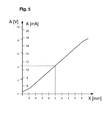
- Figure 5 shows an example diagram of the output signal A over the position X of an edge.
- This output signal A can be present as a voltage value and is approximately linear between 0 V and 10 V between a position X of -9 mm to +9 mm. If the output signal A is output as a current value, this lies between 4 mA and 20 mA. For larger deviations of the position, the output signal becomes less accurate. In the case shown here, the zero point of the position X is at an output signal A of 4 volts or 11 mA.
Landscapes
- Physics & Mathematics (AREA)
- General Physics & Mathematics (AREA)
- Length Measuring Devices Characterised By Use Of Acoustic Means (AREA)
Abstract
Description
- Die Erfindung betrifft eine Vorrichtung zur Kontrolle einer Kantenlage flächiger Objekte, insbesondere von Bahnen aus Papier oder Folie, mit einem Ultraschall-Sendewandler und einem Ultraschall-Empfangswandler, die in einem festen Abstand gegenüberliegend zueinander angeordnet sind und eine zur Fläche des Objektes senkrechte Messtrecke bilden, durch die das zu kontrollierende Objekt mit einer Kante hindurchgeführt wird, und mit einer Steuerelektronik, die die empfangenen Ultraschallsignale aufbereitet und ein Ausgangssignal ausgibt, das der Lage der Kante in der Messstrecke proportional ist.
- In vielen Bereichen der Industrie werden Flächenmaterialien wie Papier, Folien oder Bleche von der Rolle als Bahnmaterial verarbeitet. Dieses Bahnmaterial wird in den verarbeitenden Maschinen über Umlenkrollen und Zylinder geführt. Damit das Bahnmaterial in der Spur bleibt, sind einige der Umlenkrollen über Aktoren lenkbar ausgeführt, so dass die Lage des Bahnmaterials ständig nachgeregelt werden kann. Für diese Nachregelung muss die Lage der Bahnkante erfasst werden. Hierfür werden so genannte Bahnkantensensoren verwendet, die nach unterschiedlichen physikalischen Wirkprinzipien arbeiten. Gemeinsam ist allen Bahnkantensensoren, dass diese ein der Lage der Bahnkante proportionales Ausgangssignal liefern. Dies kann in Form eines Analogsignals 0-10 V oder 4-20 mA, oder eines Digitalsignals, welches über eine definierte Schnittstelle wie CAN-Bus ausgegeben wird.
- Es sind verschiedenste Formen von Kantendetektoren bekannt. Weit verbreitet sind Detektoren auf optischer Basis. So ist in der Patentanmeldung
WO2004/72609 - In der Patentschrift
DE 10 2004 017 676 B4 ist eine Fehlererfassungsvorrichtung für Druckbahnen beschrieben, bei der an beiden Seiten der Druckbahn gabelförmige Detektoren vorgesehen sind, die mit jeweils zwei Infrarot-Lichtschranken arbeiten. - Diese Detektoren sind relativ ungenau und sie sind nicht für transparente Druckbahnen geeignet.
- In der Patentanmeldung
DE 199 41 728 A1 ist ein Bogenkantendetektor beschrieben, der mit einer linearen Anordnung einer Vielzahl von Ultraschallsensoren arbeitet. Dieser Bogenkantendetektor beruht auf der unterschiedlichen Reflektion der Ultraschallsignale von dem Bogen und der Unterlage. - In der Patentanmeldung
DE 11 2007 000 959 T5 ist ein gabelförmiger Detektor mit einem optischen Array und einem Ultraschall-Array zum Senden von Messsignalen und einem optischen Array und einem Ultraschall-Array zum Empfangen von Messsignalen beschrieben. Ein solcher Detektor ist sehr aufwendig, da alle optischen und Ultraschallelemente einzeln angesteuert und ausgewertet werden müssen. - Am Markt erhältliche Ultraschallwandler sind rotationssymmetrisch aufgebaut. Baut man mit diesen Ultraschallwandlern eine Sender- Empfängeranordnung auf, ist der erzielbare Messbereich diese Anordnung bestimmt von den geometrischen Abmessungen der verwendeten Ultraschallwandler. Diese kreisrunden Ultraschallwandler lassen sich im Durchmesser nicht beliebig vergrößern, da der Durchmesser die Ultraschall-Frequenz bestimmt und bei einem sehr großen Durchmesser die Ultraschall-Frequenz so niedrig liegen würde, dass dann die Gefahr bestehen würde, durch hochfrequente Geräusche aus der Umgebung gestört zu werden. Ein zu großer Durchmesser der Ultraschallwandler würde die mechanische Breite des Bahnkantensensors auch unzulässig vergrößern. Deshalb wird in der Patentschrift
DE 195 00 822 C1 ein gabelförmiger Detektor mit jeweils einem aus einzelnen Ultraschallwandlern diskret aufgebauten Ultraschall-Array zum Senden und zum Empfangen von Messsignalen beschrieben, in der mehrere kreisrunde Sende-Empfangswandler nebeneinander angeordnet werden, so dass sich die einzelnen Messbereiche überschneiden und sich in der Summe ein breiter Messbereich ergibt. Nachteilig an dieser Lösung ist, dass mehrere Sende- und Empfangswandler benötigt werden und diese über eine sehr aufwändige Elektronik ausgewertet werden müssen. - Das Patent
WO 97/08761 - Es ist die Aufgabe der vorliegenden Erfindung, eine Vorrichtung anzugeben, die ein der Lage einer Kante von verschiedensten Objekten in einer möglichst breiten Messstrecke proportionales Signal abgibt, dass für die Steuerung der Zuführung des Objektes genutzt werden kann und mit nur einem Ultraschallsende- und nur einem Empfangswandler auskommt und somit einfach und preiswert herzustellen ist.
- Diese Aufgaben werden mit den Merkmalen des Anspruch 1 gelöst. Vorteilhafte Ausgestaltungen der Erfindung sind in den Unteransprüchen angegeben.
- Die Kontrolle der Kantenlage flächiger Objekte, insbesondere von Bahnen aus Papier oder Folie, erfolgt mit einer Vorrichtung, in der ein Ultraschall-Sendewandler und ein Ultraschall-Empfangswandler in einem festen Abstand gegenüberliegend zueinander angeordnet sind und eine Messstrecke bilden. Das zu kontrollierende Objekt wird durch die Messstrecke so hindurchgeführt, so dass die Fläche des Objektes senkrechte zur Messstrecke verläuft und die zu kontrollierende Kante sich in der Messstrecke befindet. Das abzutastende Objekt deckt einen Teil der Messstrecke ab, so dass weniger Schall vom Sender zum Empfänger gelangt je weiter das Objekt die Messstrecke abdeckt. Eine Steuerelektronik generiert das Sendesignal und bereitet das empfangene Ultraschallsignal auf, verarbeitet diese und gibt ein Ausgangssignal aus, das der Lage der Kante in der Messtrecke proportional ist.
- Die Vorrichtung zeichnet sich dadurch aus, dass sich in dem Ultraschall-Sendewandler nur eine piezokeramische Platte in länglicher Quaderform befindet und in dem gegenüberliegenden Ultraschall-Empfangswandler nur eine piezokeramische Platte ebenfalls in länglicher Quaderform befindet. Dabei sind die piezokeramische Platten jeweils auf einer länglichen Anpassungsschicht befestigt, die die Ankopplung der Ultraschallsignale an die Luft optimiert. Zwischen dem Ultraschall-Sendewandler und dem Ultraschall-Empfangswandler bildet sich die Messtrecke in einer Breite aus, die in etwa 2/3 der Länge der Sende- und Empfangswandler entspricht.
- Es hat sich gezeigt, dass mit nur einem Paar von Sende- und Empfangswandlern sich ein zur Lage der Kante in der Messstrecke proportionales Ausgangssignal ergibt, das annähernd linear ist. Bei erhöhten Anforderungen an die Genauigkeit kann das Ausgangssignal durch die Steuerung weiter linearisiert werden.
- Auf die piezokeramischen Platte mit ihren rechteckigen Abmessungen wird eine Anpassungsschicht geklebt, die die Abmessungen der piezokeramischen Platte aufweist, oder zu allen vier Seiten geringfügig übersteht. Als akustisches Anpassmaterial wird ein Epoxydharz mit einem hohen Anteil an Glashohlkugeln verwendet.
- Die Dicke der Anpassschichten wird so gewählt, dass sie ein Viertel der Wellenlänge der Ultraschallsignale beträgt.
- Eine lineare Messtrecke kann mit einem rechteckigen Ultraschall-Sendewandler und Ultraschall-Empfangswandler ab 20 mm Länge aufgebaut werden. Praktische Versuche haben gezeigt, dass mit rechteckförmigen piezokeramischen Platten mit Abmessungen von 10 x 30 x 2 mm3 bereits ein Messbereich von bis zu 18 mm erzielt werden kann. Es wurde eine sehr lineare Kennlinie erzielt, wenn die Abmessungen der akustischen Anpassschicht ebenfalls 10 x 30 mm2 betrug. Für einen noch größeren Messbereich kann auch eine rechteckförmige piezokeramische Platte mit den Abmessungen 10 x 70 x 2 mm3 verwendet werden. Durch Versuche wurde herausgefunden, dass es hier günstiger ist, wenn die akustische Anpassschicht umlaufend ca. 1 mm übersteht, also Abmessungen von 12 x 52 mm2 aufweißt. Damit lassen sich Messbereiche von bis zu 35 mm erzielen. Die Dicke der akustischen Anpassschicht wurde so gewählt, dass sich eine Ultraschallfrequenz von ca. 150 kHz einstellt.
- Sender und Empfänger können in einem Abstand von 20 mm bis 100 mm zueinander angeordnet sein. In der Praxis bewährt haben sich Abstände von 30 mm, 40 mm und 70 mm.
- Denkbar ist es auch, rechteckförmige piezokeramische Platten mit noch größeren Abmessungen zu verwenden, um einen noch breiteren Messbereich zu erzielen. Piezokeramische Platten mit rechteckförmigen Abmessungen ist eine übliche Bauform. Natürlich ist es auch denkbar, piezokeramische Platten mit rechteckförmigen Abmessungen zu nutzen, bei denen die vier Ecken der großen Rechteckfläche abgerundet sind, gegebenenfalls sogar soweit, dass sich an den beiden kurzen Seiten des Rechtecks Halbkreise ausbilden. Entsprechend könnten auch vier Ecken der Anpassschicht abgerundet sein. Dies beeinträchtigt die Funktion der UltraschallWandler nur unwesentlich.
- Die Dämpfung des Signals in der Messstrecke zwischen Ultraschall-Sendeeinheit und Ultraschall-Empfangseinheit ist nicht nur abhängig von der Lage der Kante der Materialbahn, sondern auch von der Lufttemperatur, der Luftfeuchte und dem Luftdruck. Will man die Genauigkeit der Messstrecke weiter erhöhen, kann man diese Umwelteinflüsse durch eine zusätzliche Referenzstrecke kompensieren. Diese besteht dann aus einem klein bauenden Referenz-Ultraschallsendewandler und einem Referenz-Ultraschallempfangswandler der mit einem räumlichen Abstand neben dem Ultraschall-Sendewandler und Ultraschall-Empfangswandler angeordnet ist. Die Materialbahn bewegt sich immer nur in der Messstrecke, die sich aus dem Ultraschall-Sendewandler und dem Ultraschall-Empfangswandler bildet; die Referenzstrecke bleibt immer frei vom Bahnmaterial. Dass in der Referenzstrecke gemessene Vergleichssignal wird in der Steuerelektronik herangezogen, um die Umwelteinflüsse aus Lufttemperatur, Luftfeuchtigkeit und Luftdruck in der eigentlichen Messstrecke zu kompensieren.
- Um eine gute EMV-Festigkeit zu erzielen, wird die der piezokeramischen Platte zugewandten Seite des akustischen Anpassmaterials metallisiert. Wird nun die piezokeramische Platte mithilfe eines Epoxidklebers auf die metallisierte Seite des akustischen Anpassmaterials geklebt, muss dafür Sorge getragen werden, dass die Metallisierung elektrischen Kontakt mit dem Minuspol der piezokeramischen Platte hat. Bei einer hinreichenden Rauhigkeit der Metallisierung wird dies bereits durch einen entsprechend hohen Anpressdruck während des Verklebens erzielt. Ist die Rauhigkeit nicht gegeben, können zwecks elektrischer Kontaktierung auch dünne Kupferdrähte zwischen der metallisierten Anpassschicht und der piezokeramischen Platte eingelegt und mit verklebt werden. Die piezokeramische Platte ist mit zwei Drähten am Plus- und Minuspol kontaktiert. Der rechteckförmige Verbund aus akustischem Anpassmaterial und piezokeramischer Platte wird in einen Schaumstoffkörper, zum Beispiel einem weichen Polyurethanschaum, eingebettet, so dass nur die der metallisierten Seite des akustischen Anpassmaterials gegenüberliegenden Seite freiliegt.
- Der Ultraschall-Sendewandler und der Ultraschall-Empfangswandler sind vorzugweise in einen gabelförmigen Halter eingesetzt. Die Messstrecke befindet sich dann zwischen den Innenseiten der beiden Schenkel des gabelförmigen Halters. In diesem gabelförmigen Halter ist auch die gesamte Steuerelektronik untergebracht.
- Der Halter ist vorzugsweise aus Metall hergestellt, er kann aber auch aus Kunststoff sein. Ein typischer Abstand der Schenkel zueinander beträgt etwa 40 mm.
- Das aus der Messstrecke gewonnene Ausgangssignal kann in verschiedenen Formen zur Weiterverarbeitung angeboten werden. Das Ausgangssignal kann ein der Lage der Kante proportionale Spannung zwischen 0 und 10 Volt sein. Üblich ist auch ein Stromwert zwischen 4 mA und 20 mA. Es kann aber auch ein der Lage der Kante proportionales Binärsignal sein, welches über eine standardisierte Schnittstelle, wie den CAN-Bus, ausgegeben wird.
- Ausführungsformen der Erfindung sind beispielhaft in den Figuren beschrieben.
- Fig. 1
- zeigt perspektivisch einen Blattkantensensor.
- Fig. 2
- zeigt den Einbau der Ultraschallwandler in den Halter.
- Fig. 3
- zeigt einen Längs-Querschnitt durch einen Ultraschallwandler
- Fig. 4
- zeigt eine Aufsicht auf einen Ultraschallwandler
- Fig. 5
- zeigt ein Diagramm des Ausgangssignals abhängig von der Lage der Blattkante.
- In
Fig. 1 ist ein Blattkantensensor in einem gabelförmigen Halter 1 dargestellt, zwischen dessen Schenkeln sich eine Materialbahn B befindet, deren Kante K detektiert werden soll. Dazu ist in dem einen Schenkel der Ultraschall-Sendewandler 2 und in dem anderen Schenkel der Ultraschall-Empfangswandler 3 untergebracht, zwischen denen sich die Messstrecke M ausbildet. - An dem Halter 1 steht das Ausgangssignal A zur Verfügung, das der Lage der Kante K proportional ist.
- In
Fig. 2 ist schematisch ein Schnitt durch einen Blattkantensensor gezeigt. - In dem unteren Schenkel des Halters 1 ist die Ultraschall-Sendewandler 2 eingesetzt. Sie besteht aus der piezokeramischen Platte 5 und der Anpassungsschicht 4, die zusammen mit der Dämpfungsmasse 7 in dem unteren Schenkel gehalten werden.
- In dem oberen Schenkel des Halters 1 ist der Ultraschall-Empfangswandler 3 eingesetzt. Dieser besteht ebenfalls aus der piezokeramischen Platte 5 und der Anpassungsschicht 4, die zusammen mit der Dämpfungsmasse 7 in dem oberen Schenkel gehalten werden. Zwischen dem Ultraschall-Sendewandler 2 und dem Ultraschall-Empfangswandler 3 bildet sich die Messstrecke M aus, die die Lage X eine Kante detektiert.
- Parallel zu der Messstrecke M ist die optionale Referenzstrecke R dargestellt, die aus dem Referenz-Ultraschallsendewandler 8 und dem Referenz-Ultraschallempfangswandler 9 besteht, die auch jeweils in einer Dämpfungsmasse gehalten sind.
- Die Steuerelektronik 10 steuert den Ultraschall-Sendewandler 2 an und wertet das Empfangssignal aus dem Ultraschall-Empfangswandler 3 aus.
- Das Empfangssignal wird ggf. mittels des Referenzsignals aus der Referenzstrecke R korrigiert.
- Das resultierende Signal wird als Ausgangssignal A zur Verfügung gestellt und kann für beispielsweise für Maschinensteuerungen verwendet werden.
- In den
Figuren 3 und 4 sind ein Längs-Querschnitt und eine Aufsicht auf einen - Ultraschallwandler dargestellt. Er besteht aus einer piezokeramischen Platte 5, die unter die Anpassungsschicht 4 geklebt ist. Diese ist vorzugsweise mit einer Metallisierung 11 versehen. Die Anschlussdrähte 6 führen zur Steuerelektronik, wo die Ultraschallsignale erzeugt und ausgewertet werden.
- Die Einheit aus piezokeramischer Platte 5 und Anpassungsschicht 4 ist in eine Dämpfungsmasse 7 eingebettet, über die eine Übertragung von Körperschall vermieden wird.
-
Fig.5 zeigt ein Beispiel-Diagramm des Ausgangssignal A über der Lage X einer Kante. Dieses Ausgangssignal A kann als Spannungswert vorliegen und ist zwischen einer Lage X von -9 mm bis +9 mm in etwa linear zwischen 0 V und 10 V. Wird das Ausgangssignals A als Stromwert ausgegeben, liegt dieses zwischen 4 mA und 20 mA. Bei größeren Abweichungen der Lage wird das Ausgangssignal ungenauer. Im hier gezeigten Fall liegt der Nullpunkt der Lage X bei einem Ausgangssignal A von 4 Volt oder 11 mA. -
- 1
- Halter
- 2
- Ultraschall-Sendewandler
- 3
- Ultraschall-Empfangswandler
- 4
- Anpassungsschicht
- 5
- Piezokeramische Platte
- 6
- Anschlussdrähte
- 7
- Dämpfungsmasse
- 8
- Referenz-Ultraschall-Sendewandler
- 9
- Referenz- Ultraschall-Empfangswandler
- 10
- Steuerelektronik
- 11
- Metallisierung
- A
- Ausgangssignal
- B
- Materialbahn
- K
- Kante
- M
- Messstrecke
- R
- Referenzstrecke
- X
- Lage der Kante
Claims (11)
- Vorrichtung zur Kontrolle einer Kantenlage flächiger Objekte, insbesondere von Bahnen aus Papier oder Folie, mit einem Ultraschall-Sendewandler (2) und einem Ultraschall-Empfangswandler (3), die in einem festen Abstand gegenüberliegend zueinander angeordnet sind und eine zur Fläche des Objektes senkrechte Messtrecke (M) mit Ultraschallsignalen bilden, durch die das zu kontrollierende Objekt (B) mit einer Kante (K) hindurchgeführt wird, und mit einer Steuerelektronik (10), die die Ultraschallsignale der Messstrecke M verarbeitet und ein Ausgangssignal (A) ausgibt, das der Lage der Kante (K) in der Messstrecke proportional ist, dadurch gekennzeichnet,
dass sich in dem Ultraschall-Sendewandler (2) nur eine piezokeramische Platte (5) in länglicher Quaderform befindet und in der gegenüberliegenden Ultraschall-Empfangswandler (3) nur eine piezokeramische Platte (5) ebenfalls in länglicher Quaderform befindet, wobei die piezokeramischen Platten (5) auf länglichen Anpassungsschichten (4) zur akustischen Anpassung an die Luft befestigt sind. - Vorrichtung nach Anspruch 1, dadurch gekennzeichnet,
dass der Ultraschall-Sendewandler (2) und der Ultraschall-Empfangswandler (3) jeweils ein Länge von ca. 20 mm bis 70 mm besitzen. - Vorrichtung nach Anspruch 1 oder 2, dadurch gekennzeichnet, dass die Anpassungsschicht (4) die Abmessungen der piezokeramischen Platte aufweist, oder zu allen vier Seiten geringfügig übersteht.
- Vorrichtung nach Anspruch 1, dadurch gekennzeichnet, dass die Anpassungsschichten (4) eine Dicke von einem Viertel der Wellenlänge der Ultraschallsignale besitzen.
- Vorrichtung nach Anspruch 1, dadurch gekennzeichnet, dass die Anpassungsschichten (4) eine Platte aus Epoxydharz mit Glasanteilen ist.
- Vorrichtung nach Anspruch 1, dadurch gekennzeichnet, dass der Ultraschall-Sendewandler (2) und der Ultraschall-Empfangswandler (3) in eine Dämpfungsmasse (7) eingebettet sind.
- Vorrichtung nach Anspruch 1, dadurch gekennzeichnet, dass Ultraschall-Sendewandler (2) und die Ultraschall-Empfangswandler (3) in den Schenkeln eines gabelförmigen Halters (1) untergebracht sind.
- Vorrichtung nach Anspruch 7, dadurch gekennzeichnet,
dass der Abstand der Schenkel etwa 40 mm beträgt. - Vorrichtung nach Anspruch 7, dadurch gekennzeichnet,
dass in dem Halter (1) neben der Messtrecke (M) noch eine Referenzstrecke (R) aus einem Referenz-Ultraschall-Sendewandler (8) und einem Referenz-Ultraschall-Empfangswandler (9) eingebaut ist. - Vorrichtung nach Anspruch 1, dadurch gekennzeichnet,
dass das Ausgangssignal (A) eine der Lage der Kante (K) proportionale Spannung zwischen 0 und 10 Volt und/oder ein proportionaler Strom zwischen 4 und 20 mA ist. - Vorrichtung nach Anspruch 1, dadurch gekennzeichnet,
dass das Ausgangssignal (A) eine der Lage der Kante (K) proportionales Binärsignal ist, welches über eine standardisierte Schnittstelle wie CAN-Bus ausgegeben wird.
Priority Applications (1)
| Application Number | Priority Date | Filing Date | Title |
|---|---|---|---|
| EP11174087.4A EP2546601B1 (de) | 2011-07-15 | 2011-07-15 | Vorrichtung zur berührungslosen Kontrolle der Kantenlage flächiger Objekte |
Applications Claiming Priority (1)
| Application Number | Priority Date | Filing Date | Title |
|---|---|---|---|
| EP11174087.4A EP2546601B1 (de) | 2011-07-15 | 2011-07-15 | Vorrichtung zur berührungslosen Kontrolle der Kantenlage flächiger Objekte |
Publications (2)
| Publication Number | Publication Date |
|---|---|
| EP2546601A1 true EP2546601A1 (de) | 2013-01-16 |
| EP2546601B1 EP2546601B1 (de) | 2016-09-28 |
Family
ID=44890563
Family Applications (1)
| Application Number | Title | Priority Date | Filing Date |
|---|---|---|---|
| EP11174087.4A Active EP2546601B1 (de) | 2011-07-15 | 2011-07-15 | Vorrichtung zur berührungslosen Kontrolle der Kantenlage flächiger Objekte |
Country Status (1)
| Country | Link |
|---|---|
| EP (1) | EP2546601B1 (de) |
Citations (9)
| Publication number | Priority date | Publication date | Assignee | Title |
|---|---|---|---|---|
| US5274573A (en) * | 1989-07-31 | 1993-12-28 | Accuweb, Inc. | Ultrasonic web edge detection method and apparatus |
| DE19500822C1 (de) | 1995-01-13 | 1996-03-21 | Erhardt & Leimer Gmbh | Ultraschall-Kantenfühler zur Erfassung der Bahnkante einer Warenbahn |
| WO1997008761A1 (en) | 1995-08-28 | 1997-03-06 | Accuweb, Inc. | Ultrasonic transducer units for web edge detection |
| DE19941728A1 (de) | 1998-10-08 | 2000-04-13 | Heidelberger Druckmasch Ag | Bogenkantendetektor |
| US6289729B1 (en) * | 1998-12-28 | 2001-09-18 | Fife Corporation | Ultrasonic sensor for web-guiding apparatus |
| WO2004072609A2 (en) | 2003-02-05 | 2004-08-26 | Accuweb, Inc. | Method and system for detecting the position of an edge of a web |
| US20040171936A1 (en) * | 2003-02-27 | 2004-09-02 | Murata Manufacturing Co., Ltd. | Ultrasonic transmitting/receiving device and method for fabricating the same |
| DE102004017676B4 (de) | 2004-04-10 | 2008-09-11 | Baldwin Germany Gmbh | Fehlererfassungsvorrichtung einer Rollenrotations-Druckmaschine |
| DE112007000959T5 (de) | 2006-04-17 | 2009-02-26 | Accuweb Inc., Madison | Verfahren und System zum Detektieren der Position einer Kante einer Bahn |
-
2011
- 2011-07-15 EP EP11174087.4A patent/EP2546601B1/de active Active
Patent Citations (9)
| Publication number | Priority date | Publication date | Assignee | Title |
|---|---|---|---|---|
| US5274573A (en) * | 1989-07-31 | 1993-12-28 | Accuweb, Inc. | Ultrasonic web edge detection method and apparatus |
| DE19500822C1 (de) | 1995-01-13 | 1996-03-21 | Erhardt & Leimer Gmbh | Ultraschall-Kantenfühler zur Erfassung der Bahnkante einer Warenbahn |
| WO1997008761A1 (en) | 1995-08-28 | 1997-03-06 | Accuweb, Inc. | Ultrasonic transducer units for web edge detection |
| DE19941728A1 (de) | 1998-10-08 | 2000-04-13 | Heidelberger Druckmasch Ag | Bogenkantendetektor |
| US6289729B1 (en) * | 1998-12-28 | 2001-09-18 | Fife Corporation | Ultrasonic sensor for web-guiding apparatus |
| WO2004072609A2 (en) | 2003-02-05 | 2004-08-26 | Accuweb, Inc. | Method and system for detecting the position of an edge of a web |
| US20040171936A1 (en) * | 2003-02-27 | 2004-09-02 | Murata Manufacturing Co., Ltd. | Ultrasonic transmitting/receiving device and method for fabricating the same |
| DE102004017676B4 (de) | 2004-04-10 | 2008-09-11 | Baldwin Germany Gmbh | Fehlererfassungsvorrichtung einer Rollenrotations-Druckmaschine |
| DE112007000959T5 (de) | 2006-04-17 | 2009-02-26 | Accuweb Inc., Madison | Verfahren und System zum Detektieren der Position einer Kante einer Bahn |
Also Published As
| Publication number | Publication date |
|---|---|
| EP2546601B1 (de) | 2016-09-28 |
Similar Documents
| Publication | Publication Date | Title |
|---|---|---|
| EP2559024B1 (de) | Verfahren zum ansteuern eines ultraschallsensors und ultraschallsensor | |
| DE102007047274B4 (de) | Ultraschallsensor | |
| EP2569650A1 (de) | Verfahren und vorrichtung zur bestimmung der position eines objektes relativ zu einem fahrzeug, insbesondere einem kraftfahrzeug, zur verwendung in einem fahrerassistenzsystem des fahrzeuges | |
| DE102007019689A1 (de) | Vorrichtung zur Bestimmung und/oder Überwachung des Volumen- und/oder Massedurchflusses eines Mediums | |
| DE102008049081B4 (de) | Ultraschallsensor | |
| DE102008038336A1 (de) | Ultraschallsensor | |
| DE102007014696B3 (de) | Sensor/Aktor-Vorrichtung und Verfahren zur Ermittlung von strukturellen Informationen von Materialien | |
| EP2657645B1 (de) | Vorrichtung zum Detektieren einer Kante einer Materialbahn | |
| EP2031580B1 (de) | Ultraschallsensor mit einem Trägerelement und einer Membran, wobei die Membran in das Trägerelement eingebettet ist | |
| DE10151593A1 (de) | Abstands- und Druckmessung innerhalb einer Luftfeder | |
| EP3110611B1 (de) | Ultraschallbearbeitungsvorrichtung mit kraftsensor | |
| DE102009020676B4 (de) | Vorrichtung und Verfahren zur Positionsbestimmung | |
| EP3359975B1 (de) | Sensor mit monolithischen ultraschallarray | |
| EP2546601B1 (de) | Vorrichtung zur berührungslosen Kontrolle der Kantenlage flächiger Objekte | |
| WO2009024403A1 (de) | Koppelelement für ein ultraschall-durchflussmessgerät | |
| DE102011014995A1 (de) | Vorrichtung zur Bearbeitung von Werkstücken | |
| WO2017174391A1 (de) | Ultraschall-prüfkopf und ultraschall-prüfanlage | |
| WO2002061413A2 (de) | Ultraschall-sensor für die prozesssteuerung beim widerstandspunktschweissen | |
| EP2415679A1 (de) | Ultraschallsensor | |
| EP1510487A1 (de) | Verfahren und Vorrichtung zum Erfassen der Lage einer Kante einer laufenden Warenbahn | |
| DE19941728B4 (de) | Bogenkantendetektor | |
| DE202011002054U1 (de) | Ultraschall-Kantensensor | |
| EP1701900B1 (de) | Verfahren und vorrichtung zur berührungslosen detektion von flächigen objekten | |
| DE102008039221A1 (de) | Vorrichtung zur berührungslosen Kontrolle von flächigen Objekten | |
| EP1701901B1 (de) | Verfahren und vorrichtung zur berührungslosen detektion von flächigen objekten |
Legal Events
| Date | Code | Title | Description |
|---|---|---|---|
| PUAI | Public reference made under article 153(3) epc to a published international application that has entered the european phase |
Free format text: ORIGINAL CODE: 0009012 |
|
| 17P | Request for examination filed |
Effective date: 20120503 |
|
| AK | Designated contracting states |
Kind code of ref document: A1 Designated state(s): AL AT BE BG CH CY CZ DE DK EE ES FI FR GB GR HR HU IE IS IT LI LT LU LV MC MK MT NL NO PL PT RO RS SE SI SK SM TR |
|
| AX | Request for extension of the european patent |
Extension state: BA ME |
|
| 17Q | First examination report despatched |
Effective date: 20140709 |
|
| GRAP | Despatch of communication of intention to grant a patent |
Free format text: ORIGINAL CODE: EPIDOSNIGR1 |
|
| INTG | Intention to grant announced |
Effective date: 20160512 |
|
| RIN1 | Information on inventor provided before grant (corrected) |
Inventor name: SCHULTE, JOHANNES Inventor name: WETTERKAMP, JOERG |
|
| RAP1 | Party data changed (applicant data changed or rights of an application transferred) |
Owner name: MICROSONIC GMBH |
|
| GRAS | Grant fee paid |
Free format text: ORIGINAL CODE: EPIDOSNIGR3 |
|
| GRAA | (expected) grant |
Free format text: ORIGINAL CODE: 0009210 |
|
| AK | Designated contracting states |
Kind code of ref document: B1 Designated state(s): AL AT BE BG CH CY CZ DE DK EE ES FI FR GB GR HR HU IE IS IT LI LT LU LV MC MK MT NL NO PL PT RO RS SE SI SK SM TR |
|
| REG | Reference to a national code |
Ref country code: GB Ref legal event code: FG4D Free format text: NOT ENGLISH |
|
| REG | Reference to a national code |
Ref country code: CH Ref legal event code: EP |
|
| REG | Reference to a national code |
Ref country code: AT Ref legal event code: REF Ref document number: 833147 Country of ref document: AT Kind code of ref document: T Effective date: 20161015 |
|
| REG | Reference to a national code |
Ref country code: IE Ref legal event code: FG4D Free format text: LANGUAGE OF EP DOCUMENT: GERMAN |
|
| REG | Reference to a national code |
Ref country code: DE Ref legal event code: R096 Ref document number: 502011010774 Country of ref document: DE |
|
| GRAT | Correction requested after decision to grant or after decision to maintain patent in amended form |
Free format text: ORIGINAL CODE: EPIDOSNCDEC |
|
| REG | Reference to a national code |
Ref country code: NL Ref legal event code: FP |
|
| REG | Reference to a national code |
Ref country code: LT Ref legal event code: MG4D |
|
| PG25 | Lapsed in a contracting state [announced via postgrant information from national office to epo] |
Ref country code: LT Free format text: LAPSE BECAUSE OF FAILURE TO SUBMIT A TRANSLATION OF THE DESCRIPTION OR TO PAY THE FEE WITHIN THE PRESCRIBED TIME-LIMIT Effective date: 20160928 Ref country code: HR Free format text: LAPSE BECAUSE OF FAILURE TO SUBMIT A TRANSLATION OF THE DESCRIPTION OR TO PAY THE FEE WITHIN THE PRESCRIBED TIME-LIMIT Effective date: 20160928 Ref country code: NO Free format text: LAPSE BECAUSE OF FAILURE TO SUBMIT A TRANSLATION OF THE DESCRIPTION OR TO PAY THE FEE WITHIN THE PRESCRIBED TIME-LIMIT Effective date: 20161228 Ref country code: RS Free format text: LAPSE BECAUSE OF FAILURE TO SUBMIT A TRANSLATION OF THE DESCRIPTION OR TO PAY THE FEE WITHIN THE PRESCRIBED TIME-LIMIT Effective date: 20160928 Ref country code: FI Free format text: LAPSE BECAUSE OF FAILURE TO SUBMIT A TRANSLATION OF THE DESCRIPTION OR TO PAY THE FEE WITHIN THE PRESCRIBED TIME-LIMIT Effective date: 20160928 |
|
| PG25 | Lapsed in a contracting state [announced via postgrant information from national office to epo] |
Ref country code: GR Free format text: LAPSE BECAUSE OF FAILURE TO SUBMIT A TRANSLATION OF THE DESCRIPTION OR TO PAY THE FEE WITHIN THE PRESCRIBED TIME-LIMIT Effective date: 20161229 Ref country code: SE Free format text: LAPSE BECAUSE OF FAILURE TO SUBMIT A TRANSLATION OF THE DESCRIPTION OR TO PAY THE FEE WITHIN THE PRESCRIBED TIME-LIMIT Effective date: 20160928 Ref country code: LV Free format text: LAPSE BECAUSE OF FAILURE TO SUBMIT A TRANSLATION OF THE DESCRIPTION OR TO PAY THE FEE WITHIN THE PRESCRIBED TIME-LIMIT Effective date: 20160928 |
|
| PG25 | Lapsed in a contracting state [announced via postgrant information from national office to epo] |
Ref country code: RO Free format text: LAPSE BECAUSE OF FAILURE TO SUBMIT A TRANSLATION OF THE DESCRIPTION OR TO PAY THE FEE WITHIN THE PRESCRIBED TIME-LIMIT Effective date: 20160928 Ref country code: EE Free format text: LAPSE BECAUSE OF FAILURE TO SUBMIT A TRANSLATION OF THE DESCRIPTION OR TO PAY THE FEE WITHIN THE PRESCRIBED TIME-LIMIT Effective date: 20160928 |
|
| PG25 | Lapsed in a contracting state [announced via postgrant information from national office to epo] |
Ref country code: PL Free format text: LAPSE BECAUSE OF FAILURE TO SUBMIT A TRANSLATION OF THE DESCRIPTION OR TO PAY THE FEE WITHIN THE PRESCRIBED TIME-LIMIT Effective date: 20160928 Ref country code: CZ Free format text: LAPSE BECAUSE OF FAILURE TO SUBMIT A TRANSLATION OF THE DESCRIPTION OR TO PAY THE FEE WITHIN THE PRESCRIBED TIME-LIMIT Effective date: 20160928 Ref country code: BG Free format text: LAPSE BECAUSE OF FAILURE TO SUBMIT A TRANSLATION OF THE DESCRIPTION OR TO PAY THE FEE WITHIN THE PRESCRIBED TIME-LIMIT Effective date: 20161228 Ref country code: SK Free format text: LAPSE BECAUSE OF FAILURE TO SUBMIT A TRANSLATION OF THE DESCRIPTION OR TO PAY THE FEE WITHIN THE PRESCRIBED TIME-LIMIT Effective date: 20160928 Ref country code: PT Free format text: LAPSE BECAUSE OF FAILURE TO SUBMIT A TRANSLATION OF THE DESCRIPTION OR TO PAY THE FEE WITHIN THE PRESCRIBED TIME-LIMIT Effective date: 20170130 Ref country code: ES Free format text: LAPSE BECAUSE OF FAILURE TO SUBMIT A TRANSLATION OF THE DESCRIPTION OR TO PAY THE FEE WITHIN THE PRESCRIBED TIME-LIMIT Effective date: 20160928 Ref country code: IS Free format text: LAPSE BECAUSE OF FAILURE TO SUBMIT A TRANSLATION OF THE DESCRIPTION OR TO PAY THE FEE WITHIN THE PRESCRIBED TIME-LIMIT Effective date: 20170128 Ref country code: SM Free format text: LAPSE BECAUSE OF FAILURE TO SUBMIT A TRANSLATION OF THE DESCRIPTION OR TO PAY THE FEE WITHIN THE PRESCRIBED TIME-LIMIT Effective date: 20160928 |
|
| REG | Reference to a national code |
Ref country code: DE Ref legal event code: R097 Ref document number: 502011010774 Country of ref document: DE |
|
| REG | Reference to a national code |
Ref country code: FR Ref legal event code: PLFP Year of fee payment: 7 |
|
| PG25 | Lapsed in a contracting state [announced via postgrant information from national office to epo] |
Ref country code: DK Free format text: LAPSE BECAUSE OF FAILURE TO SUBMIT A TRANSLATION OF THE DESCRIPTION OR TO PAY THE FEE WITHIN THE PRESCRIBED TIME-LIMIT Effective date: 20160928 |
|
| PLBE | No opposition filed within time limit |
Free format text: ORIGINAL CODE: 0009261 |
|
| STAA | Information on the status of an ep patent application or granted ep patent |
Free format text: STATUS: NO OPPOSITION FILED WITHIN TIME LIMIT |
|
| 26N | No opposition filed |
Effective date: 20170629 |
|
| PG25 | Lapsed in a contracting state [announced via postgrant information from national office to epo] |
Ref country code: SI Free format text: LAPSE BECAUSE OF FAILURE TO SUBMIT A TRANSLATION OF THE DESCRIPTION OR TO PAY THE FEE WITHIN THE PRESCRIBED TIME-LIMIT Effective date: 20160928 |
|
| REG | Reference to a national code |
Ref country code: IE Ref legal event code: MM4A |
|
| PG25 | Lapsed in a contracting state [announced via postgrant information from national office to epo] |
Ref country code: IE Free format text: LAPSE BECAUSE OF NON-PAYMENT OF DUE FEES Effective date: 20170715 |
|
| REG | Reference to a national code |
Ref country code: BE Ref legal event code: MM Effective date: 20170731 |
|
| PG25 | Lapsed in a contracting state [announced via postgrant information from national office to epo] |
Ref country code: LU Free format text: LAPSE BECAUSE OF NON-PAYMENT OF DUE FEES Effective date: 20170715 |
|
| REG | Reference to a national code |
Ref country code: FR Ref legal event code: PLFP Year of fee payment: 8 |
|
| PG25 | Lapsed in a contracting state [announced via postgrant information from national office to epo] |
Ref country code: BE Free format text: LAPSE BECAUSE OF NON-PAYMENT OF DUE FEES Effective date: 20170731 |
|
| PG25 | Lapsed in a contracting state [announced via postgrant information from national office to epo] |
Ref country code: MT Free format text: LAPSE BECAUSE OF FAILURE TO SUBMIT A TRANSLATION OF THE DESCRIPTION OR TO PAY THE FEE WITHIN THE PRESCRIBED TIME-LIMIT Effective date: 20160928 |
|
| PG25 | Lapsed in a contracting state [announced via postgrant information from national office to epo] |
Ref country code: AL Free format text: LAPSE BECAUSE OF FAILURE TO SUBMIT A TRANSLATION OF THE DESCRIPTION OR TO PAY THE FEE WITHIN THE PRESCRIBED TIME-LIMIT Effective date: 20160928 |
|
| PG25 | Lapsed in a contracting state [announced via postgrant information from national office to epo] |
Ref country code: HU Free format text: LAPSE BECAUSE OF FAILURE TO SUBMIT A TRANSLATION OF THE DESCRIPTION OR TO PAY THE FEE WITHIN THE PRESCRIBED TIME-LIMIT; INVALID AB INITIO Effective date: 20110715 Ref country code: MC Free format text: LAPSE BECAUSE OF FAILURE TO SUBMIT A TRANSLATION OF THE DESCRIPTION OR TO PAY THE FEE WITHIN THE PRESCRIBED TIME-LIMIT Effective date: 20160928 |
|
| PG25 | Lapsed in a contracting state [announced via postgrant information from national office to epo] |
Ref country code: CY Free format text: LAPSE BECAUSE OF NON-PAYMENT OF DUE FEES Effective date: 20160928 |
|
| PG25 | Lapsed in a contracting state [announced via postgrant information from national office to epo] |
Ref country code: MK Free format text: LAPSE BECAUSE OF FAILURE TO SUBMIT A TRANSLATION OF THE DESCRIPTION OR TO PAY THE FEE WITHIN THE PRESCRIBED TIME-LIMIT Effective date: 20160928 |
|
| PG25 | Lapsed in a contracting state [announced via postgrant information from national office to epo] |
Ref country code: TR Free format text: LAPSE BECAUSE OF FAILURE TO SUBMIT A TRANSLATION OF THE DESCRIPTION OR TO PAY THE FEE WITHIN THE PRESCRIBED TIME-LIMIT Effective date: 20160928 |
|
| P01 | Opt-out of the competence of the unified patent court (upc) registered |
Effective date: 20230601 |
|
| REG | Reference to a national code |
Ref country code: DE Ref legal event code: R082 Ref document number: 502011010774 Country of ref document: DE Representative=s name: WICKORD BUSER PATENTANWAELTE PARTG MBB, DE |
|
| PGFP | Annual fee paid to national office [announced via postgrant information from national office to epo] |
Ref country code: NL Payment date: 20250723 Year of fee payment: 15 |
|
| PGFP | Annual fee paid to national office [announced via postgrant information from national office to epo] |
Ref country code: DE Payment date: 20250728 Year of fee payment: 15 |
|
| PGFP | Annual fee paid to national office [announced via postgrant information from national office to epo] |
Ref country code: IT Payment date: 20250731 Year of fee payment: 15 |
|
| PGFP | Annual fee paid to national office [announced via postgrant information from national office to epo] |
Ref country code: GB Payment date: 20250724 Year of fee payment: 15 |
|
| PGFP | Annual fee paid to national office [announced via postgrant information from national office to epo] |
Ref country code: FR Payment date: 20250723 Year of fee payment: 15 Ref country code: AT Payment date: 20250721 Year of fee payment: 15 |
|
| PGFP | Annual fee paid to national office [announced via postgrant information from national office to epo] |
Ref country code: CH Payment date: 20250801 Year of fee payment: 15 |