EP2546501A1 - Malfunction detection device for engine and malfunction detection method for engine - Google Patents
Malfunction detection device for engine and malfunction detection method for engine Download PDFInfo
- Publication number
- EP2546501A1 EP2546501A1 EP12175666A EP12175666A EP2546501A1 EP 2546501 A1 EP2546501 A1 EP 2546501A1 EP 12175666 A EP12175666 A EP 12175666A EP 12175666 A EP12175666 A EP 12175666A EP 2546501 A1 EP2546501 A1 EP 2546501A1
- Authority
- EP
- European Patent Office
- Prior art keywords
- fuel
- reduction
- opening command
- pressure
- valve opening
- Prior art date
- Legal status (The legal status is an assumption and is not a legal conclusion. Google has not performed a legal analysis and makes no representation as to the accuracy of the status listed.)
- Withdrawn
Links
Images


Classifications
-
- F—MECHANICAL ENGINEERING; LIGHTING; HEATING; WEAPONS; BLASTING
- F02—COMBUSTION ENGINES; HOT-GAS OR COMBUSTION-PRODUCT ENGINE PLANTS
- F02D—CONTROLLING COMBUSTION ENGINES
- F02D41/00—Electrical control of supply of combustible mixture or its constituents
- F02D41/30—Controlling fuel injection
- F02D41/38—Controlling fuel injection of the high pressure type
- F02D41/3809—Common rail control systems
- F02D41/3836—Controlling the fuel pressure
- F02D41/3863—Controlling the fuel pressure by controlling the flow out of the common rail, e.g. using pressure relief valves
-
- F—MECHANICAL ENGINEERING; LIGHTING; HEATING; WEAPONS; BLASTING
- F02—COMBUSTION ENGINES; HOT-GAS OR COMBUSTION-PRODUCT ENGINE PLANTS
- F02D—CONTROLLING COMBUSTION ENGINES
- F02D41/00—Electrical control of supply of combustible mixture or its constituents
- F02D41/22—Safety or indicating devices for abnormal conditions
-
- F—MECHANICAL ENGINEERING; LIGHTING; HEATING; WEAPONS; BLASTING
- F02—COMBUSTION ENGINES; HOT-GAS OR COMBUSTION-PRODUCT ENGINE PLANTS
- F02D—CONTROLLING COMBUSTION ENGINES
- F02D41/00—Electrical control of supply of combustible mixture or its constituents
- F02D41/22—Safety or indicating devices for abnormal conditions
- F02D41/221—Safety or indicating devices for abnormal conditions relating to the failure of actuators or electrically driven elements
-
- F—MECHANICAL ENGINEERING; LIGHTING; HEATING; WEAPONS; BLASTING
- F02—COMBUSTION ENGINES; HOT-GAS OR COMBUSTION-PRODUCT ENGINE PLANTS
- F02D—CONTROLLING COMBUSTION ENGINES
- F02D41/00—Electrical control of supply of combustible mixture or its constituents
- F02D41/22—Safety or indicating devices for abnormal conditions
- F02D2041/224—Diagnosis of the fuel system
Definitions
- the invention relates to a malfunction detection device for an engine and a malfunction detection method for an engine, which detect a state where a pressure reducing valve that discharges fuel from a fuel system of an engine to reduce fuel pressure in the fuel system is stuck closed, as a malfunction.
- a common rail diesel engine that is provided with a common rail in which high-pressure fuel is accumulated has been placed into practical use, as is well known.
- the fuel supplied through the common rail is injected into combustion chambers of the engine.
- raising of fuel pressure has been promoted to improve injection response and promote atomization of sprayed fuel in the above-described common rail diesel engine.
- the raising of fuel pressure has caused a demand for improvement in the accuracy of control on the pressure of fuel accumulated in the common rail (rail pressure).
- the rail pressure is controlled through control on an amount of fuel that is pressurized and supplied to the common rail by a high-pressure fuel pump, and control on a pressure reducing valve that discharges the fuel from the common rail.
- a pressure reducing valve there is employed a normally-closed valve that provides communication between the inside of a common rail and a relief passage with the use of an electromagnetic attraction force that is generated by the passage of electric current through a solenoid, for example.
- a valve closing operation failure occurs, that is, the pressure reducing valve is not fully closed even when the passage of electric current through the solenoid is interrupted, in some cases.
- a malfunction detection device for an engine which detects a valve closing operation failure of a pressure reducing valve as described above, a device described in Japanese Patent Application Publication No. 2006-257883 ( JP 2006-257883 A ) is known.
- a reference pressure reduction amount is set to the sum of a pressure reduction amount that is estimated from an upper limit of a fuel release amount, which is defined in a performance standard of the pressure reducing valve, and a pressure reduction amount that is estimated from an upper limit of a fuel leakage amount, which is defined in a performance standard of the injectors. If an amount of reduction in rail pressure after the pressure reducing valve is opened after the engine is stopped is equal to or larger than the reference pressure reduction amount, it is determined that a valve closing operation failure has occurred in the pressure reducing valve.
- Malfunctions of the pressure reducing valve include not only the valve closing operation failure described above but also a malfunction that the pressure reducing valve is stuck closed and does not open, due to a stuck valve element, even when electric current is passed through the solenoid. It is possible to detect a state where the pressure reducing valve is stuck closed by detecting a fact that the rail pressure is not reduced even when a command to open the pressure reducing valve is provided after the engine is stopped.
- the factors causing increases in the amount of reduction in rail pressure include not only opening of the pressure reducing valve but also fuel leakage from the fuel system due to foreign matter caught in a valve portion of an injector and foreign matter caught in a spill valve of a high-pressure fuel pump.
- the invention provides a malfunction detection device for an engine and a malfunction detection method for an engine, which are able to more appropriately detect whether a pressure reducing valve is stuck closed.
- a first aspect of the invention relates to a malfunction detection device for an engine, which detects whether a pressure reducing valve that discharges fuel from a fuel system of an engine to reduce fuel pressure in the fuel system is stuck closed.
- the malfunction detection device is configured to provide a valve opening command to open the pressure reducing valve after the engine is stopped, detect an amount of reduction in the fuel pressure per unit time before the valve opening command is provided and an amount of reduction in the fuel pressure per unit time after the valve opening command is provided, and determine whether the pressure reducing valve is stuck closed based on the detected amount of reduction in the fuel pressure per unit time before the valve opening command is provided and the detected amount of reduction in the fuel pressure per unit time after the valve opening command is provided.
- the malfunction detection device may be configured to determine that the pressure reducing valve is stuck closed when there is no change between the detected amount of reduction in the fuel pressure per unit time before the valve opening command for the pressure reducing valve is provided and the detected amount of reduction in the fuel pressure per unit time after the valve opening command for the pressure reducing valve is provided.
- the fuel pressure in the fuel system is reduced regardless of whether the pressure reducing valve is opened or closed.
- the pressure reducing valve is actually opened in response to the command, the rate of reduction in the fuel pressure, that is, the amount of reduction in the fuel pressure per unit time should increase. Accordingly, if the amount of reduction in the fuel pressure per unit time is not changed even though the command to open the pressure reducing valve is provided, it is determined that the pressure reducing valve is not opened despite provision of the valve opening command, that is, the pressure reducing valve is stuck closed. Therefore, with the above configuration, it is possible to more appropriately detect whether the pressure reducing valve is stuck closed.
- the malfunction detection device may be configured to determine whether the pressure reducing valve is stuck closed based on a difference between the detected amount of reduction in the fuel pressure per unit time before the valve opening command is provided and the detected amount of reduction in the fuel pressure per unit time after the valve opening command is provided.
- the fuel pressure in the fuel system is reduced regardless of whether the pressure reducing valve is opened or closed. In this case as well, if the pressure reducing valve is actually opened in response to the command, the rate of reduction in the fuel pressure, that is, the amount of reduction in the fuel pressure per unit time should be larger than that before the command is provided.
- the difference between the amount of reduction in the fuel pressure per unit time before the valve opening command is provided and the amount of reduction in the fuel pressure per unit time after the valve opening command is provided is approximately zero, it is determined that the pressure reducing valve is not opened despite provision of the valve opening command, that is, the pressure reducing valve is stuck closed. Therefore, with the above configuration, it is possible to more appropriately detect whether the pressure reducing valve is stuck closed.
- the malfunction detection device may be configured to determine whether the pressure reducing valve is stuck closed based on a ratio of the detected amount of reduction in the fuel pressure per unit time after the valve opening command is provided to the detected amount of reduction in the fuel pressure per unit time before the valve opening command is provided.
- the fuel pressure in the fuel system is reduced regardless of whether the pressure reducing valve is opened or closed.
- the pressure reducing valve is actually opened in response to the command, the amount of reduction in the fuel pressure per unit time should be larger than that before the command is provided. Accordingly, if the ratio of the amount of reduction in the fuel pressure per unit time after the valve opening command is provided to the amount of reduction in the fuel pressure per unit time before the valve opening command is provided is approximately one, it is determined that the pressure reducing valve is not opened despite provision of the valve opening command, that is, the pressure reducing valve is stuck closed. Therefore, with the above configuration, it is possible to more appropriately detect whether the pressure reducing valve is stuck closed.
- the malfunction detection device for an engine according to the above aspect may be applied to a common rail diesel engine in which a pressure reducing valve is configured as a valve that discharges fuel from a common rail.
- a second aspect of the invention relates to a malfunction detection method for an engine, for detecting whether a pressure reducing valve that discharges fuel from a fuel system of an engine to reduce fuel pressure in the fuel system is stuck closed.
- the malfunction detection method includes: detecting an amount of reduction in the fuel pressure per unit time after the engine is stopped; providing a valve opening command to open the pressure reducing valve; detecting an amount of reduction in the fuel pressure per unit time after the valve opening command is provided; and determining whether the pressure reducing valve is stuck closed based on the detected amount of reduction in the fuel pressure per unit time before the valve opening command is provided and the detected amount of reduction in the fuel pressure per unit time after the valve opening command is provided.
- the malfunction detection device according to the embodiment is applied to a common rail diesel engine.
- the fuel stored in a fuel tank 1 is drawn up by a high-pressure fuel pump 2.
- the high-pressure fuel pump 2 that is driven by a crankshaft pressurizes the fuel drawn up from the fuel tank 1 and then discharges the pressurized fuel.
- the high-pressure fuel discharged from the high-pressure fuel pump 2 is delivered to a common rail 4.
- the high-pressure fuel pump 2 is provided with a spill valve by which excess fuel is returned to the fuel tank 1 through a check valve 3.
- the common rail 4 which is an accumulator pipe, is provided with a rail pressure sensor 5 that detects a fuel pressure inside the common rail 4, that is, a rail pressure. Further, the common rail 4 is provided with a pressure reducing valve 6. The fuel discharged from the common rail 4 upon opening of the pressure reducing valve 6 is returned to the fuel tank 1 through the check valve 3.
- Injectors 7 for respective cylinders are connected to the common rail 4.
- the high-pressure fuel accumulated inside the common rail 4 is distributed to the injectors 7 for the respective cylinders. Then, the fuel is injected from the injectors 7 to combustion chambers of the diesel engine.
- the excess fuel, that is, the fuel that is supplied to the injectors 7 but is not injected from the injectors 7, is returned to the fuel tank 1 through the check valve 3.
- the common rail diesel engine that has the above-described fuel system is controlled by an electronic control unit 8 for engine control.
- the electronic control unit 8 includes a central processing unit (CPU) that executes various calculations related to engine control, a read-only memory (ROM) that stores programs and data for the engine control, and a random access memory (RAM) that temporarily stores, for example, calculation results obtained by the CPU and detection results obtained by sensors provided at various portions of the engine.
- the electronic control unit 8 adjusts an amount of fuel that is pumped from the high-pressure fuel pump 2 and an amount of fuel that is discharged from the common rail 4 through the pressure reducing valve 6, based on the detection results obtained by the rail pressure sensor 5. In this way, the electronic control unit 8 controls the rail pressure so that a target value of the rail pressure is achieved.
- the electronic control unit 8 transmits command signals to solenoid valves of the injectors 7 to control fuel injection timing and a fuel injection amount.
- the electronic control unit 8 determines whether the pressure reducing valve 6 is stuck closed when the engine is stopped. The determination is made through the process of a routine for determining whether the valve is stuck closed as shown in FIG. 2 .
- the process of the routine is started by the electronic control unit 8 when an ignition switch is turned off. When the ignition switch is turned off, the pressure reducing valve 6 is closed.
- step S101 an amount of reduction in fuel pressure (rail pressure) per unit time, that is, a rate of reduction in fuel pressure is detected in step S101.
- a valve opening command is output to the pressure reducing valve 6 (i.e., a valve opening command for the pressure reducing valve 6 is provided ) in step S102.
- an amount of reduction in fuel pressure (rail pressure) per unit time that is, a rate of reduction in fuel pressure is detected again in step S103.
- step S104 After detection of the rate of reduction in fuel pressure before the output of the valve opening command and detection of the rate of reduction in fuel pressure after the output of the valve opening command are completed, it is determined in step S104 whether there is a change in rate of reduction in fuel pressure between before and after the output of the valve opening command.
- Whether there is a change in rate of reduction in fuel pressure between before and after the output of the valve opening command is determined, for example, by determining whether a difference in rate of reduction in fuel pressure between before and after the output of the valve opening command is equal to or larger than a predetermined reference value, or by determining whether a ratio of the rate of reduction in fuel pressure after the output of the valve opening command to the rate of reduction in fuel pressure before the output of the valve opening command is equal to or higher than a predetermined reference value.
- step S105 If a condition that there is no change in rate of reduction in fuel pressure between before and after the output of the valve opening command is satisfied (YES in S104), it is determined in step S105 that the pressure reducing valve 106 is stuck closed, and then the process of the routine ends. On the other hand, if there is a significant change in rate of reduction in fuel pressure between before and after the output of the valve opening command, in other words, if the condition that there is no change in rate of reduction in fuel pressure between before and after the output of the valve opening command is not satisfied (NO in S104), it is determined in step S106 that the pressure reducing valve 6 is not stuck closed and then the process of the routine ends.
- the ignition switch (IG switch) is turned off. Then, based on a reduction amount ⁇ Pref of the fuel pressure (rail pressure), that is, an amount by which the fuel pressure (rail pressure) is reduced until a lapse of a predetermined period TA after the ignition switch is turned off at time t0, an amount of reduction in fuel pressure per unit time, that is, a reduction rate ⁇ Pref/TA is calculated.
- a reduction amount ⁇ Pref of the fuel pressure (rail pressure) that is, an amount by which the fuel pressure (rail pressure) is reduced until a lapse of a predetermined period TA after the ignition switch is turned off at time t0.
- a valve opening command is output to the pressure reducing valve 6. Then, based on a reduction amount ⁇ P, that is, an amount by which the fuel pressure (rail pressure) is reduced until a lapse of a predetermined period TB after the valve opening command is output at time t1, an amount of reduction in fuel pressure per unit time, that is, a reduction rate ⁇ P/TB is calculated.
- a reduction amount ⁇ P that is, an amount by which the fuel pressure (rail pressure) is reduced until a lapse of a predetermined period TB after the valve opening command is output at time t1
- the pressure reducing valve 6 remains closed even if the valve opening command is output.
- the fuel is not discharged from the common rail 4, and the fuel pressure inside the common rail 4 (rail pressure) remains unchanged. Therefore, in this case, the rate of reduction in fuel pressure remains at zero even after the valve opening command is output, and there is no significant difference in rate of reduction in fuel pressure between before and after the output of the valve opening command.
- the electronic control unit 8 determines that the pressure reducing valve 6 is stuck closed.
- the ignition switch (IG switch) is turned off.
- a reduction amount ⁇ Pref of the fuel pressure (rail pressure) that is, an amount by which the fuel pressure (rail pressure) is reduced until a lapse of a predetermined period TA after the ignition switch is turned off at time t0
- an amount of reduction in fuel pressure per unit time that is, a reduction rate ⁇ Pref/TA is calculated.
- the fuel pressure (rail pressure) inside the common rail 4 is reduced over time due to the fuel leakage at the injector 7 or at the high-pressure fuel pump 2. Therefore, the fuel pressure reduction rate APref/TA in this case is a positive value.
- a valve opening command is output to the pressure reducing valve 6. Then, based on a reduction amount ⁇ P, that is, an amount by which the fuel pressure (rail pressure) is reduced until a lapse of a predetermined period TB after the valve opening command is output at time t1, an amount of reduction in fuel pressure per unit time, that is, a reduction rate ⁇ P/TB is calculated.
- a reduction amount ⁇ P that is, an amount by which the fuel pressure (rail pressure) is reduced until a lapse of a predetermined period TB after the valve opening command is output at time t1
- the fuel is discharged from the common rail 4.
- the rate of reduction in fuel pressure is higher than that before the output of the valve opening command to the pressure reducing valve 6. Accordingly, in this case, there is a significant difference in rate of reduction in fuel pressure between before and after the output of the valve opening command. As a result, the electronic control unit 8 determines that the pressure reducing valve 6 is not stuck closed.
- the pressure reducing valve 6 determines that the pressure reducing valve 6 is stuck closed.
- the command (the valve opening command) to open the pressure reducing valve 6 is output after the engine is stopped. Then, the amount of reduction in fuel pressure per unit time before the output of the valve opening command and the amount of reduction in fuel pressure per unit time after the output of the valve opening command are detected. Based on the detection results, whether the pressure reducing valve 6 is stuck closed is determined.
- the amount of reduction in fuel pressure per unit time before the output of the valve opening command and the amount of reduction in fuel pressure per unit time after the output of the valve opening command are detected, and then, if there is no change in amount of reduction in fuel pressure per unit time between before and after the output of the valve opening command, it is determined that the pressure reducing valve 6 is stuck closed.
- the rate of reduction in fuel pressure is calculated based on the amount of reduction in fuel pressure.
- it is possible to determine whether the pressure reducing valve 6 is stuck closed by measuring amounts of reduction in the fuel pressure over the same period of time before and after an output of the valve opening command and directly comparing the reduction amounts with each other.
- the period TA and the period TB in FIG. 3 and FIG. 4 are set to the same length of period, it is possible to use the amounts of reduction in the fuel pressure during the period TA and the period TB as the amounts of reduction in the fuel pressure per unit time, and calculations for obtaining the rates of reduction in the fuel pressure are omitted.
- the rail pressure is used as the fuel pressure in the fuel system.
- the fuel pressure at another portion of the fuel system such as the fuel pressure inside the injector 7 is used, it is possible to determine whether the pressure reducing valve 6 is stuck closed in a manner similar to that described above.
- the malfunction detection device according to the invention is applied to the common rail diesel engine provided with the pressure reducing valve 6 which is configured as a valve that discharges fuel from the common rail 4.
- the malfunction detection device according to the invention is applicable to an engine provided with a pressure reducing valve that is provided at a portion other than a common rail in a fuel system and that discharges fuel from the fuel system to reduce the fuel pressure in the fuel system.
- the malfunction detection device according to the invention is applied to the common rail diesel engine.
- the invention may be applied also to engines other than the common rail diesel engine as long as the engines have a fuel system that includes a pressure reducing valve that discharges fuel from the fuel system to reduce the fuel pressure of the fuel system.
Landscapes
- Engineering & Computer Science (AREA)
- Chemical & Material Sciences (AREA)
- Combustion & Propulsion (AREA)
- Mechanical Engineering (AREA)
- General Engineering & Computer Science (AREA)
- Fuel-Injection Apparatus (AREA)
- Combined Controls Of Internal Combustion Engines (AREA)
Abstract
Description
- The invention relates to a malfunction detection device for an engine and a malfunction detection method for an engine, which detect a state where a pressure reducing valve that discharges fuel from a fuel system of an engine to reduce fuel pressure in the fuel system is stuck closed, as a malfunction.
- A common rail diesel engine that is provided with a common rail in which high-pressure fuel is accumulated has been placed into practical use, as is well known. The fuel supplied through the common rail is injected into combustion chambers of the engine. In recent years, raising of fuel pressure has been promoted to improve injection response and promote atomization of sprayed fuel in the above-described common rail diesel engine. The raising of fuel pressure has caused a demand for improvement in the accuracy of control on the pressure of fuel accumulated in the common rail (rail pressure). The rail pressure is controlled through control on an amount of fuel that is pressurized and supplied to the common rail by a high-pressure fuel pump, and control on a pressure reducing valve that discharges the fuel from the common rail.
- As a pressure reducing valve, there is employed a normally-closed valve that provides communication between the inside of a common rail and a relief passage with the use of an electromagnetic attraction force that is generated by the passage of electric current through a solenoid, for example. In the pressure reducing valve, a valve closing operation failure occurs, that is, the pressure reducing valve is not fully closed even when the passage of electric current through the solenoid is interrupted, in some cases. As a malfunction detection device for an engine, which detects a valve closing operation failure of a pressure reducing valve as described above, a device described in Japanese Patent Application Publication No.
2006-257883 JP 2006-257883 A JP 2006-257883 A - Malfunctions of the pressure reducing valve include not only the valve closing operation failure described above but also a malfunction that the pressure reducing valve is stuck closed and does not open, due to a stuck valve element, even when electric current is passed through the solenoid. It is possible to detect a state where the pressure reducing valve is stuck closed by detecting a fact that the rail pressure is not reduced even when a command to open the pressure reducing valve is provided after the engine is stopped. However, the factors causing increases in the amount of reduction in rail pressure include not only opening of the pressure reducing valve but also fuel leakage from the fuel system due to foreign matter caught in a valve portion of an injector and foreign matter caught in a spill valve of a high-pressure fuel pump. Therefore, if foreign matter is caught in the valve portion of the injector or the spill valve of the high-pressure fuel pump, the rail pressure is reduced even though the pressure reducing valve is not opened. Therefore, it is not possible to appropriately detect whether the pressure reducing valve is stuck closed, when the pressure reducing valve is stuck closed and, in addition, a failure that increases an amount of reduction in rail pressure has occurred.
- The invention provides a malfunction detection device for an engine and a malfunction detection method for an engine, which are able to more appropriately detect whether a pressure reducing valve is stuck closed.
- A first aspect of the invention relates to a malfunction detection device for an engine, which detects whether a pressure reducing valve that discharges fuel from a fuel system of an engine to reduce fuel pressure in the fuel system is stuck closed. The malfunction detection device is configured to provide a valve opening command to open the pressure reducing valve after the engine is stopped, detect an amount of reduction in the fuel pressure per unit time before the valve opening command is provided and an amount of reduction in the fuel pressure per unit time after the valve opening command is provided, and determine whether the pressure reducing valve is stuck closed based on the detected amount of reduction in the fuel pressure per unit time before the valve opening command is provided and the detected amount of reduction in the fuel pressure per unit time after the valve opening command is provided.
- If fuel leakage from the fuel system has occurred due to foreign matter caught in a valve portion of an injector or foreign matter caught in a spill valve of a high-pressure fuel pump, the fuel pressure in the fuel system is reduced regardless of whether the pressure reducing valve is opened or closed. In this case, reduction in the fuel pressure due to the fuel leakage occurs before the pressure reducing valve is opened, and both reduction in the fuel pressure due to the fuel leakage and reduction in the fuel pressure due to opening of the pressure reducing valve occur after the pressure reducing valve is opened. Therefore, even when the fuel pressure is reduced due to a factor other than opening of the pressure reducing valve, it is possible to determine whether the amount of reduction in the fuel pressure is increased due to opening of the pressure reducing valve, that is, whether the pressure reducing valve is actually opened in response to the valve opening command, by comparing the amount of reduction in the fuel pressure per unit time before the valve opening command for the pressure reducing valve is provided with the amount of reduction in the fuel pressure per unit time after the valve opening command is provided. Therefore, with the above configuration, it is possible to more appropriately detect whether the pressure reducing valve is stuck closed.
- In the above aspect, the malfunction detection device may be configured to determine that the pressure reducing valve is stuck closed when there is no change between the detected amount of reduction in the fuel pressure per unit time before the valve opening command for the pressure reducing valve is provided and the detected amount of reduction in the fuel pressure per unit time after the valve opening command for the pressure reducing valve is provided.
- If fuel leakage from the fuel system has occurred due to, for example, foreign matter caught in the valve portion of the injector or foreign matter caught in the spill valve of the high-pressure fuel pump, the fuel pressure in the fuel system is reduced regardless of whether the pressure reducing valve is opened or closed. In this case as well, if the pressure reducing valve is actually opened in response to the command, the rate of reduction in the fuel pressure, that is, the amount of reduction in the fuel pressure per unit time should increase. Accordingly, if the amount of reduction in the fuel pressure per unit time is not changed even though the command to open the pressure reducing valve is provided, it is determined that the pressure reducing valve is not opened despite provision of the valve opening command, that is, the pressure reducing valve is stuck closed. Therefore, with the above configuration, it is possible to more appropriately detect whether the pressure reducing valve is stuck closed.
- In the above aspect, the malfunction detection device may be configured to determine whether the pressure reducing valve is stuck closed based on a difference between the detected amount of reduction in the fuel pressure per unit time before the valve opening command is provided and the detected amount of reduction in the fuel pressure per unit time after the valve opening command is provided.
- If fuel leakage from the fuel system has occurred due to, for example, foreign matter caught in the valve portion of the injector or foreign matter caught in the spill valve of the high-pressure fuel pump, the fuel pressure in the fuel system is reduced regardless of whether the pressure reducing valve is opened or closed. In this case as well, if the pressure reducing valve is actually opened in response to the command, the rate of reduction in the fuel pressure, that is, the amount of reduction in the fuel pressure per unit time should be larger than that before the command is provided. Accordingly, if the difference between the amount of reduction in the fuel pressure per unit time before the valve opening command is provided and the amount of reduction in the fuel pressure per unit time after the valve opening command is provided is approximately zero, it is determined that the pressure reducing valve is not opened despite provision of the valve opening command, that is, the pressure reducing valve is stuck closed. Therefore, with the above configuration, it is possible to more appropriately detect whether the pressure reducing valve is stuck closed.
- In the above aspect, the malfunction detection device may be configured to determine whether the pressure reducing valve is stuck closed based on a ratio of the detected amount of reduction in the fuel pressure per unit time after the valve opening command is provided to the detected amount of reduction in the fuel pressure per unit time before the valve opening command is provided.
- If fuel leakage from the fuel system has occurred due to, for example, foreign matter caught in the valve portion of the injector or foreign matter caught in the spill valve of the high-pressure fuel pump, the fuel pressure in the fuel system is reduced regardless of whether the pressure reducing valve is opened or closed. In this case as well, if the pressure reducing valve is actually opened in response to the command, the amount of reduction in the fuel pressure per unit time should be larger than that before the command is provided. Accordingly, if the ratio of the amount of reduction in the fuel pressure per unit time after the valve opening command is provided to the amount of reduction in the fuel pressure per unit time before the valve opening command is provided is approximately one, it is determined that the pressure reducing valve is not opened despite provision of the valve opening command, that is, the pressure reducing valve is stuck closed. Therefore, with the above configuration, it is possible to more appropriately detect whether the pressure reducing valve is stuck closed.
- The malfunction detection device for an engine according to the above aspect may be applied to a common rail diesel engine in which a pressure reducing valve is configured as a valve that discharges fuel from a common rail.
- A second aspect of the invention relates to a malfunction detection method for an engine, for detecting whether a pressure reducing valve that discharges fuel from a fuel system of an engine to reduce fuel pressure in the fuel system is stuck closed. The malfunction detection method includes: detecting an amount of reduction in the fuel pressure per unit time after the engine is stopped; providing a valve opening command to open the pressure reducing valve; detecting an amount of reduction in the fuel pressure per unit time after the valve opening command is provided; and determining whether the pressure reducing valve is stuck closed based on the detected amount of reduction in the fuel pressure per unit time before the valve opening command is provided and the detected amount of reduction in the fuel pressure per unit time after the valve opening command is provided.
- Features, advantages, and technical and industrial significance of exemplary embodiments of the invention will be described below with reference to the accompanying drawings, in which like numerals denote like elements, and wherein:
-
FIG. 1 is a schematic view showing the structure of a fuel system of a common rail diesel engine to which a malfunction detection device for an engine according to an embodiment of the invention is applied; -
FIG. 2 is a flowchart showing the process of a routine for determining whether a valve is stuck closed according to the embodiment; -
FIG. 3 is a time chart showing an example of a control mode for determining whether the valve is stuck closed according to the embodiment when there is no fuel leakage; and -
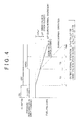
FIG. 4 is a time chart showing an example of a control mode for determining whether the valve is stuck closed according to the embodiment when there is fuel - Hereafter, a malfunction detection device for an engine according to an embodiment of the invention will be described in detail with reference to
FIG. 1 to FIG. 4 . The malfunction detection device according to the embodiment is applied to a common rail diesel engine. - First, the structure of a common rail diesel engine to which the malfunction detection device according to the embodiment is applied will be described with reference to
FIG. 1 . The fuel stored in afuel tank 1 is drawn up by a high-pressure fuel pump 2. The high-pressure fuel pump 2 that is driven by a crankshaft pressurizes the fuel drawn up from thefuel tank 1 and then discharges the pressurized fuel. The high-pressure fuel discharged from the high-pressure fuel pump 2 is delivered to acommon rail 4. The high-pressure fuel pump 2 is provided with a spill valve by which excess fuel is returned to thefuel tank 1 through acheck valve 3. - The
common rail 4, which is an accumulator pipe, is provided with arail pressure sensor 5 that detects a fuel pressure inside thecommon rail 4, that is, a rail pressure. Further, thecommon rail 4 is provided with apressure reducing valve 6. The fuel discharged from thecommon rail 4 upon opening of thepressure reducing valve 6 is returned to thefuel tank 1 through thecheck valve 3. -
Injectors 7 for respective cylinders are connected to thecommon rail 4. The high-pressure fuel accumulated inside thecommon rail 4 is distributed to theinjectors 7 for the respective cylinders. Then, the fuel is injected from theinjectors 7 to combustion chambers of the diesel engine. The excess fuel, that is, the fuel that is supplied to theinjectors 7 but is not injected from theinjectors 7, is returned to thefuel tank 1 through thecheck valve 3. - The common rail diesel engine that has the above-described fuel system is controlled by an
electronic control unit 8 for engine control. Theelectronic control unit 8 includes a central processing unit (CPU) that executes various calculations related to engine control, a read-only memory (ROM) that stores programs and data for the engine control, and a random access memory (RAM) that temporarily stores, for example, calculation results obtained by the CPU and detection results obtained by sensors provided at various portions of the engine. Theelectronic control unit 8 adjusts an amount of fuel that is pumped from the high-pressure fuel pump 2 and an amount of fuel that is discharged from thecommon rail 4 through thepressure reducing valve 6, based on the detection results obtained by therail pressure sensor 5. In this way, theelectronic control unit 8 controls the rail pressure so that a target value of the rail pressure is achieved. In addition, theelectronic control unit 8 transmits command signals to solenoid valves of theinjectors 7 to control fuel injection timing and a fuel injection amount. - In the common rail diesel engine configured as described above, the
electronic control unit 8 determines whether thepressure reducing valve 6 is stuck closed when the engine is stopped. The determination is made through the process of a routine for determining whether the valve is stuck closed as shown inFIG. 2 . The process of the routine is started by theelectronic control unit 8 when an ignition switch is turned off. When the ignition switch is turned off, thepressure reducing valve 6 is closed. - When the process of the routine is started, first, an amount of reduction in fuel pressure (rail pressure) per unit time, that is, a rate of reduction in fuel pressure is detected in step S101. When the detection is completed, a valve opening command is output to the pressure reducing valve 6 (i.e., a valve opening command for the
pressure reducing valve 6 is provided ) in step S102. Then, after the output of the valve opening command, an amount of reduction in fuel pressure (rail pressure) per unit time, that is, a rate of reduction in fuel pressure is detected again in step S103. - After detection of the rate of reduction in fuel pressure before the output of the valve opening command and detection of the rate of reduction in fuel pressure after the output of the valve opening command are completed, it is determined in step S104 whether there is a change in rate of reduction in fuel pressure between before and after the output of the valve opening command. Whether there is a change in rate of reduction in fuel pressure between before and after the output of the valve opening command is determined, for example, by determining whether a difference in rate of reduction in fuel pressure between before and after the output of the valve opening command is equal to or larger than a predetermined reference value, or by determining whether a ratio of the rate of reduction in fuel pressure after the output of the valve opening command to the rate of reduction in fuel pressure before the output of the valve opening command is equal to or higher than a predetermined reference value.
- If a condition that there is no change in rate of reduction in fuel pressure between before and after the output of the valve opening command is satisfied (YES in S104), it is determined in step S105 that the pressure reducing valve 106 is stuck closed, and then the process of the routine ends. On the other hand, if there is a significant change in rate of reduction in fuel pressure between before and after the output of the valve opening command, in other words, if the condition that there is no change in rate of reduction in fuel pressure between before and after the output of the valve opening command is not satisfied (NO in S104), it is determined in step S106 that the
pressure reducing valve 6 is not stuck closed and then the process of the routine ends. - Next, operations of the thus configured malfunction detection device for an engine according to the embodiment will be described. First, with reference to
FIG. 3 , description will be provided regarding a control mode when there has not occurred fuel leakage from the fuel system due to foreign matter caught in a valve portion of the solenoid valve of theinjector 7 or foreign matter caught in the spill valve of the high-pressure fuel pump 2. - At time t0 in
FIG. 3 , the ignition switch (IG switch) is turned off. Then, based on a reduction amount ΔPref of the fuel pressure (rail pressure), that is, an amount by which the fuel pressure (rail pressure) is reduced until a lapse of a predetermined period TA after the ignition switch is turned off at time t0, an amount of reduction in fuel pressure per unit time, that is, a reduction rate ΔPref/TA is calculated. When the ignition switch is turned off, thepressure reducing valve 6 is closed. If there is no fuel leakage, the fuel pressure inside thecommon rail 4 is maintained. Therefore, in this case, the fuel pressure reduction amount ΔPref and the fuel pressure reduction rate ΔPref/TA are both zero. - At time t1 at which the calculation is completed, a valve opening command is output to the
pressure reducing valve 6. Then, based on a reduction amount ΔP, that is, an amount by which the fuel pressure (rail pressure) is reduced until a lapse of a predetermined period TB after the valve opening command is output at time t1, an amount of reduction in fuel pressure per unit time, that is, a reduction rate ΔP/TB is calculated. - If there is no malfunction in the
pressure reducing valve 6 and thepressure reducing valve 6 is opened in response to the above-described valve opening command, the fuel is discharged from thecommon rail 4 and the fuel pressure (rail pressure) inside thecommon rail 4 is reduced. In this case, there is a significant difference in rate of reduction in fuel pressure between before and after the output of the valve opening command. As a result, theelectronic control unit 8 determines that thepressure reducing valve 6 is not stuck closed. - If the
pressure reducing valve 6 is stuck closed, thepressure reducing valve 6 remains closed even if the valve opening command is output. The fuel is not discharged from thecommon rail 4, and the fuel pressure inside the common rail 4 (rail pressure) remains unchanged. Therefore, in this case, the rate of reduction in fuel pressure remains at zero even after the valve opening command is output, and there is no significant difference in rate of reduction in fuel pressure between before and after the output of the valve opening command. As a result, theelectronic control unit 8 determines that thepressure reducing valve 6 is stuck closed. - Next, with reference to
FIG. 4 , description will be provided regarding a control mode when there has occurred fuel leakage from the fuel system due to foreign matter caught in the valve portion of the solenoid valve of theinjector 7 or foreign matter caught in the spill valve of the high-pressure fuel pump 2. - At time t0 in
FIG. 4 , the ignition switch (IG switch) is turned off. In this case as well, based on a reduction amount ΔPref of the fuel pressure (rail pressure), that is, an amount by which the fuel pressure (rail pressure) is reduced until a lapse of a predetermined period TA after the ignition switch is turned off at time t0, an amount of reduction in fuel pressure per unit time, that is, a reduction rate ΔPref/TA is calculated. In this case, the fuel pressure (rail pressure) inside thecommon rail 4 is reduced over time due to the fuel leakage at theinjector 7 or at the high-pressure fuel pump 2. Therefore, the fuel pressure reduction rate APref/TA in this case is a positive value. - At time t1 at which the calculation is completed, a valve opening command is output to the
pressure reducing valve 6. Then, based on a reduction amount ΔP, that is, an amount by which the fuel pressure (rail pressure) is reduced until a lapse of a predetermined period TB after the valve opening command is output at time t1, an amount of reduction in fuel pressure per unit time, that is, a reduction rate ΔP/TB is calculated. - If there is no malfunction in the
pressure reducing valve 6 and thepressure reducing valve 6 is opened in response to the above valve opening command, the fuel is discharged from thecommon rail 4. In this case, because the fuel is discharged from thepressure reducing valve 6 when fuel leakage has occurred at theinjector 7 or at the high-pressure fuel pump 2, the rate of reduction in fuel pressure is higher than that before the output of the valve opening command to thepressure reducing valve 6. Accordingly, in this case, there is a significant difference in rate of reduction in fuel pressure between before and after the output of the valve opening command. As a result, theelectronic control unit 8 determines that thepressure reducing valve 6 is not stuck closed. - On the other hand, if the
pressure reducing valve 6 is stuck closed, thepressure reducing valve 6 remains closed even if the valve opening command is output, and the fuel is not discharged from thecommon rail 4. Therefore, in this case, the fuel pressure is reduced due to only the fuel leakage at theinjector 7 or at the high-pressure fuel pump 2, and the rate of reduction in fuel pressure after the output of the valve opening command is unchanged from that before the output of the valve opening command. Therefore, in this case, there is no significant difference in rate of reduction in fuel pressure between before and after the output of the valve opening command. As a result, theelectronic control unit 8 determines that thepressure reducing valve 6 is stuck closed. - With the malfunction detection device for an engine according to the embodiment described above, it is possible to produce the following advantageous effect. In the embodiment, the command (the valve opening command) to open the
pressure reducing valve 6 is output after the engine is stopped. Then, the amount of reduction in fuel pressure per unit time before the output of the valve opening command and the amount of reduction in fuel pressure per unit time after the output of the valve opening command are detected. Based on the detection results, whether thepressure reducing valve 6 is stuck closed is determined. More specifically, the amount of reduction in fuel pressure per unit time before the output of the valve opening command and the amount of reduction in fuel pressure per unit time after the output of the valve opening command are detected, and then, if there is no change in amount of reduction in fuel pressure per unit time between before and after the output of the valve opening command, it is determined that thepressure reducing valve 6 is stuck closed. This makes it possible to accurately determine whether thepressure reducing valve 6 is stuck closed, regardless of whether there has occurred fuel leakage from the fuel system due to, for example, foreign matter caught in the valve portion of the solenoid valve in theinjector 7 or foreign matter caught in the spill valve of the high-pressure fuel pump 2. Therefore, according to the embodiment, it is possible to more accurately detect whether thepressure reducing valve 6 is stuck closed. - The following modifications may be made to the above embodiment. In the above embodiment, the rate of reduction in fuel pressure is calculated based on the amount of reduction in fuel pressure. Alternatively, it is possible to determine whether the
pressure reducing valve 6 is stuck closed, by measuring amounts of reduction in the fuel pressure over the same period of time before and after an output of the valve opening command and directly comparing the reduction amounts with each other. In other words, if the period TA and the period TB inFIG. 3 andFIG. 4 are set to the same length of period, it is possible to use the amounts of reduction in the fuel pressure during the period TA and the period TB as the amounts of reduction in the fuel pressure per unit time, and calculations for obtaining the rates of reduction in the fuel pressure are omitted. - In the above embodiment, the rail pressure is used as the fuel pressure in the fuel system. However, even if the fuel pressure at another portion of the fuel system such as the fuel pressure inside the
injector 7 is used, it is possible to determine whether thepressure reducing valve 6 is stuck closed in a manner similar to that described above. - In the above embodiment, the malfunction detection device according to the invention is applied to the common rail diesel engine provided with the
pressure reducing valve 6 which is configured as a valve that discharges fuel from thecommon rail 4. However, the malfunction detection device according to the invention is applicable to an engine provided with a pressure reducing valve that is provided at a portion other than a common rail in a fuel system and that discharges fuel from the fuel system to reduce the fuel pressure in the fuel system. - In the above embodiment, the malfunction detection device according to the invention is applied to the common rail diesel engine. However, the invention may be applied also to engines other than the common rail diesel engine as long as the engines have a fuel system that includes a pressure reducing valve that discharges fuel from the fuel system to reduce the fuel pressure of the fuel system.
Claims (9)
- A malfunction detection device for an engine, which detects whether a pressure reducing valve (6) that discharges fuel from a fuel system of an engine to reduce fuel pressure in the fuel system is stuck closed, characterized in that
the malfunction detection device is configured to provide a valve opening command to open the pressure reducing valve (6) after the engine is stopped, detect an amount of reduction in the fuel pressure per unit time before the valve opening command is provided and an amount of reduction in the fuel pressure per unit time after the valve opening command is provided, and determine whether the pressure reducing valve (6) is stuck closed based on the detected amount of reduction in the fuel pressure per unit time before the valve opening command is provided and the detected amount of reduction in the fuel pressure per unit time after the valve opening command is provided. - The malfunction detection device according to claim 1, wherein the malfunction detection device is configured to determine that the pressure reducing valve (6) is stuck closed when there is no change between the detected amount of reduction in the fuel pressure per unit time before the valve opening command for the pressure reducing valve (6) is provided and the detected amount of reduction in the fuel pressure per unit time after the valve opening command for the pressure reducing valve (6) is provided.
- The malfunction detection device according to claim 1, wherein the malfunction detection device is configured to determine whether the pressure reducing valve (6) is stuck closed based on a difference between the detected amount of reduction in the fuel pressure per unit time before the valve opening command is provided and the detected amount of reduction in the fuel pressure per unit time after the valve opening command is provided.
- The malfunction detection device according to claim 1, wherein the malfunction detection device is configured to determine whether the pressure reducing valve (6) is stuck closed based on a ratio of the detected amount of reduction in the fuel pressure per unit time after the valve opening command is provided to the detected amount of reduction in the fuel pressure per unit time before the valve opening command is provided.
- The malfunction detection device according to any one of claims 1 to 4, wherein the pressure reducing valve (6) is configured as a valve which discharges fuel from a common rail (4) of a common rail diesel engine.
- A malfunction detection method for an engine, for detecting whether a pressure reducing valve (6) that discharges fuel from a fuel system of an engine to reduce fuel pressure in the fuel system is stuck closed, characterized by comprising:detecting an amount of reduction in the fuel pressure per unit time after the engine is stopped;providing a valve opening command to open the pressure reducing valve (6);detecting an amount of reduction in the fuel pressure per unit time after the valve opening command is provided; anddetermining whether the pressure reducing valve (6) is stuck closed based on the detected amount of reduction in the fuel pressure per unit time before the valve opening command is provided and the detected amount of reduction in the fuel pressure per unit time after the valve opening command is provided.
- The malfunction detection method according to claim 6, wherein it is determined that the pressure reducing valve (6) is stuck closed when there is no change between the detected amount of reduction in the fuel pressure per unit time before the valve opening command for the pressure reducing valve (6) is provided and the detected amount of reduction in the fuel pressure per unit time after the valve opening command for the pressure reducing valve (6) is provided.
- The malfunction detection method according to claim 6, wherein whether the pressure reducing valve (6) is stuck closed is determined based on a difference between the detected amount of reduction in the fuel pressure per unit time before the valve opening command is provided and the detected amount of reduction in the fuel pressure per unit time after the valve opening command is provided.
- The malfunction detection method according to claim 6, wherein whether the pressure reducing valve (6) is stuck closed is determined based on a ratio of the detected amount of reduction in the fuel pressure per unit time after the valve opening command is provided to the detected amount of reduction in the fuel pressure per unit time before the valve opening command is provided.
Applications Claiming Priority (1)
| Application Number | Priority Date | Filing Date | Title |
|---|---|---|---|
| JP2011153088A JP5454522B2 (en) | 2011-07-11 | 2011-07-11 | Engine abnormality detection device |
Publications (1)
| Publication Number | Publication Date |
|---|---|
| EP2546501A1 true EP2546501A1 (en) | 2013-01-16 |
Family
ID=47008269
Family Applications (1)
| Application Number | Title | Priority Date | Filing Date |
|---|---|---|---|
| EP12175666A Withdrawn EP2546501A1 (en) | 2011-07-11 | 2012-07-10 | Malfunction detection device for engine and malfunction detection method for engine |
Country Status (2)
| Country | Link |
|---|---|
| EP (1) | EP2546501A1 (en) |
| JP (1) | JP5454522B2 (en) |
Cited By (2)
| Publication number | Priority date | Publication date | Assignee | Title |
|---|---|---|---|---|
| CN113482823A (en) * | 2021-07-02 | 2021-10-08 | 东风商用车有限公司 | Method and device for diagnosing faults of fuel injection system and automobile with device |
| CN113803184A (en) * | 2020-06-12 | 2021-12-17 | 卓品智能科技无锡有限公司 | Method for detecting whether pressure limiting valve is clamped at closed position |
Families Citing this family (5)
| Publication number | Priority date | Publication date | Assignee | Title |
|---|---|---|---|---|
| JP6156203B2 (en) * | 2014-03-07 | 2017-07-05 | 株式会社デンソー | Pump characteristic learning device for fuel pump |
| JP6330516B2 (en) * | 2014-06-27 | 2018-05-30 | トヨタ自動車株式会社 | Abnormality judgment device for weight reduction valve |
| KR101807024B1 (en) * | 2016-03-25 | 2018-01-10 | 현대자동차 주식회사 | Device and method for controlling of valve |
| JP6714537B2 (en) * | 2017-04-24 | 2020-06-24 | 株式会社デンソー | Relief valve determination device for high pressure fuel supply system |
| JP7494769B2 (en) * | 2021-03-17 | 2024-06-04 | 株式会社豊田自動織機 | Control device for internal combustion engine system |
Citations (7)
| Publication number | Priority date | Publication date | Assignee | Title |
|---|---|---|---|---|
| EP1327762A2 (en) * | 2002-01-11 | 2003-07-16 | Robert Bosch Gmbh | Method, computer programme and control and/or regulation device for operating an internal combustion engine, and internal combustion engine |
| JP2006257883A (en) | 2005-03-15 | 2006-09-28 | Denso Corp | Fuel injection device |
| DE102005028137A1 (en) * | 2005-06-17 | 2006-12-28 | Robert Bosch Gmbh | Fuel injection quantity measuring method for internal combustion engine in motor vehicle, involves comparing pressure drop rates of valves in built-in condition, or with absolute threshold value for determining quantity of valves |
| US7278405B2 (en) * | 2005-10-06 | 2007-10-09 | Denso Corporation | Fuel injection system designed to ensure enhanced reliability of diagnosis of valve |
| EP1903210A1 (en) * | 2005-07-13 | 2008-03-26 | Toyota Jidosha Kabushiki Kaisha | Diagnosis device for electromagnetic relief valve in fuel delivery device |
| US20090164086A1 (en) * | 2007-12-20 | 2009-06-25 | Mert Geveci | System for determining critical on-times for fuel injectors |
| DE102009002945A1 (en) * | 2008-05-20 | 2009-12-03 | Denso Corporation, Kariya-City | Fuel supply control apparatus for a fuel supply system of vehicle has abnormality determination unit that determines abnormality of the relief valve based on the detected feed pressure and the estimated feed pressure |
Family Cites Families (1)
| Publication number | Priority date | Publication date | Assignee | Title |
|---|---|---|---|---|
| JP2011064100A (en) * | 2009-09-16 | 2011-03-31 | Hitachi Automotive Systems Ltd | Fuel supply system diagnostic device for internal combustion engine |
-
2011
- 2011-07-11 JP JP2011153088A patent/JP5454522B2/en not_active Expired - Fee Related
-
2012
- 2012-07-10 EP EP12175666A patent/EP2546501A1/en not_active Withdrawn
Patent Citations (8)
| Publication number | Priority date | Publication date | Assignee | Title |
|---|---|---|---|---|
| EP1327762A2 (en) * | 2002-01-11 | 2003-07-16 | Robert Bosch Gmbh | Method, computer programme and control and/or regulation device for operating an internal combustion engine, and internal combustion engine |
| JP2006257883A (en) | 2005-03-15 | 2006-09-28 | Denso Corp | Fuel injection device |
| DE102006000117A1 (en) * | 2005-03-15 | 2006-11-30 | Denso Corp., Kariya | Fuel-injection apparatus for internal combustion engine of motor vehicle has valve closing abnormality determination unit judges irregularity generated to valve closing operation of pressure reduction valve |
| DE102005028137A1 (en) * | 2005-06-17 | 2006-12-28 | Robert Bosch Gmbh | Fuel injection quantity measuring method for internal combustion engine in motor vehicle, involves comparing pressure drop rates of valves in built-in condition, or with absolute threshold value for determining quantity of valves |
| EP1903210A1 (en) * | 2005-07-13 | 2008-03-26 | Toyota Jidosha Kabushiki Kaisha | Diagnosis device for electromagnetic relief valve in fuel delivery device |
| US7278405B2 (en) * | 2005-10-06 | 2007-10-09 | Denso Corporation | Fuel injection system designed to ensure enhanced reliability of diagnosis of valve |
| US20090164086A1 (en) * | 2007-12-20 | 2009-06-25 | Mert Geveci | System for determining critical on-times for fuel injectors |
| DE102009002945A1 (en) * | 2008-05-20 | 2009-12-03 | Denso Corporation, Kariya-City | Fuel supply control apparatus for a fuel supply system of vehicle has abnormality determination unit that determines abnormality of the relief valve based on the detected feed pressure and the estimated feed pressure |
Cited By (4)
| Publication number | Priority date | Publication date | Assignee | Title |
|---|---|---|---|---|
| CN113803184A (en) * | 2020-06-12 | 2021-12-17 | 卓品智能科技无锡有限公司 | Method for detecting whether pressure limiting valve is clamped at closed position |
| CN113803184B (en) * | 2020-06-12 | 2023-08-29 | 卓品智能科技无锡有限公司 | Method for detecting whether pressure limiting valve is clamped at closed position |
| CN113482823A (en) * | 2021-07-02 | 2021-10-08 | 东风商用车有限公司 | Method and device for diagnosing faults of fuel injection system and automobile with device |
| CN113482823B (en) * | 2021-07-02 | 2023-03-03 | 东风商用车有限公司 | Method and device for diagnosing fault of fuel injection system and automobile with device |
Also Published As
| Publication number | Publication date |
|---|---|
| JP2013019311A (en) | 2013-01-31 |
| JP5454522B2 (en) | 2014-03-26 |
Similar Documents
| Publication | Publication Date | Title |
|---|---|---|
| JP4424395B2 (en) | Fuel injection control device for internal combustion engine | |
| EP2546501A1 (en) | Malfunction detection device for engine and malfunction detection method for engine | |
| US9279404B2 (en) | Fuel supply device and fuel supply control method for internal combustion engine | |
| US7210459B2 (en) | Common-rail fuel injection system | |
| EP1832737B1 (en) | Abnormality-determining device and method for fuel supply system | |
| US8789511B2 (en) | Controller for pressure reducing valve | |
| US8061331B2 (en) | Fuel injector for internal combustion engine | |
| JP5141723B2 (en) | Fuel injection control device for internal combustion engine | |
| US8800355B2 (en) | Pressure accumulation fuel injection device | |
| US9938924B2 (en) | Control device and control method for fuel injection valve | |
| US8955490B2 (en) | Fuel-pressure-sensor diagnosis device | |
| US9617947B2 (en) | Fuel injection control device | |
| JP4349451B2 (en) | Fuel injection control device and fuel injection system using the same | |
| CN110617153B (en) | fuel supply system | |
| US20130024092A1 (en) | Device for preventing the engine from stalling in a vehicle equipped with a diesel injection system | |
| JP5959060B2 (en) | Pressure limit valve opening detection method and common rail fuel injection control device | |
| JP4730613B2 (en) | Common rail fuel injection system | |
| JP4689695B2 (en) | Fuel injection system | |
| CN113494404A (en) | Method control device and readable storage medium for detecting valve seat wear of solenoid valve of fuel injector | |
| JP2007113503A (en) | Reliability evaluation system for high-pressure fuel systems | |
| GB2644082A (en) | Method for operating a fuel injection system | |
| JP6094464B2 (en) | Fuel injection control device | |
| JP5616149B2 (en) | Rail pressure offset control method and common rail fuel injection control device | |
| JP2007218208A (en) | Fuel injection device | |
| JP2011127485A (en) | Accumulator fuel injection device |
Legal Events
| Date | Code | Title | Description |
|---|---|---|---|
| PUAI | Public reference made under article 153(3) epc to a published international application that has entered the european phase |
Free format text: ORIGINAL CODE: 0009012 |
|
| 17P | Request for examination filed |
Effective date: 20120731 |
|
| AK | Designated contracting states |
Kind code of ref document: A1 Designated state(s): AL AT BE BG CH CY CZ DE DK EE ES FI FR GB GR HR HU IE IS IT LI LT LU LV MC MK MT NL NO PL PT RO RS SE SI SK SM TR |
|
| AX | Request for extension of the european patent |
Extension state: BA ME |
|
| RAP1 | Party data changed (applicant data changed or rights of an application transferred) |
Owner name: TOYOTA JIDOSHA KABUSHIKI KAISHA |
|
| STAA | Information on the status of an ep patent application or granted ep patent |
Free format text: STATUS: EXAMINATION IS IN PROGRESS |
|
| 17Q | First examination report despatched |
Effective date: 20170724 |
|
| STAA | Information on the status of an ep patent application or granted ep patent |
Free format text: STATUS: THE APPLICATION IS DEEMED TO BE WITHDRAWN |
|
| 18D | Application deemed to be withdrawn |
Effective date: 20220823 |