EP2546133A2 - Two-Wheeled Motor Vehicle - Google Patents
Two-Wheeled Motor Vehicle Download PDFInfo
- Publication number
- EP2546133A2 EP2546133A2 EP12174759A EP12174759A EP2546133A2 EP 2546133 A2 EP2546133 A2 EP 2546133A2 EP 12174759 A EP12174759 A EP 12174759A EP 12174759 A EP12174759 A EP 12174759A EP 2546133 A2 EP2546133 A2 EP 2546133A2
- Authority
- EP
- European Patent Office
- Prior art keywords
- storage box
- upper edge
- seat
- cover
- motor vehicle
- Prior art date
- Legal status (The legal status is an assumption and is not a legal conclusion. Google has not performed a legal analysis and makes no representation as to the accuracy of the status listed.)
- Granted
Links
Images







Classifications
-
- B—PERFORMING OPERATIONS; TRANSPORTING
- B62—LAND VEHICLES FOR TRAVELLING OTHERWISE THAN ON RAILS
- B62K—CYCLES; CYCLE FRAMES; CYCLE STEERING DEVICES; RIDER-OPERATED TERMINAL CONTROLS SPECIALLY ADAPTED FOR CYCLES; CYCLE AXLE SUSPENSIONS; CYCLE SIDECARS, FORECARS, OR THE LIKE
- B62K19/00—Cycle frames
- B62K19/46—Luggage carriers forming part of frame
-
- B—PERFORMING OPERATIONS; TRANSPORTING
- B62—LAND VEHICLES FOR TRAVELLING OTHERWISE THAN ON RAILS
- B62K—CYCLES; CYCLE FRAMES; CYCLE STEERING DEVICES; RIDER-OPERATED TERMINAL CONTROLS SPECIALLY ADAPTED FOR CYCLES; CYCLE AXLE SUSPENSIONS; CYCLE SIDECARS, FORECARS, OR THE LIKE
- B62K2202/00—Motorised scooters
Definitions
- the present invention relates to a two-wheeled motor vehicle, and in particular to a structure of a storage box placed below the seat and that of a cover placed beside the storage box.
- Japanese Patent Laid-open Publication No. 2008-155905 describes a two-wheeled motor vehicle having a storage box placed below a seat that is mounted so as to be opened and closed. A flange spreading outward is formed on the upper edge of the storage box. The lateral part of the seat is bent downward so as to go farther away from the lateral surface of the storage box as it goes downward.
- the present invention has been conceived in view of the above described situation, and a main object thereof is to provide a two-wheeled motor vehicle capable of ensuring an increased capacity of the storage box, while reducing increase of the seat width, and moreover, to have a member placed below be hardly seen through the space between the storage box and the cover, and preventing introduction of foreign matters and a hand through the space.
- a two-wheeled motor vehicle comprising a vehicle body frame, a storage box supported by the vehicle body frame, a seat placed above the storage box, being capable of opening and closing an opening defined by an upper edge of the storage box, and a cover placed beside the storage box.
- a lateral part of a bottom surface of the seat is bent downward and opposed to a lateral surface of the storage box so as to go farther away from the lateral surface of the storage box as it goes downward.
- An upper edge of the cover is positioned, in a side view, higher than a lower edge of a lateral part of the seat lower than the upper edge of the storage box.
- the lateral surface of the storage box has a projection formed thereon at a position lower than the upper edge thereof, the projection overlapping the upper edge of the cover in a plan view.
- no flange that spreads outward is formed on the upper edge of the storage box, and instead, a projection is formed at a position lower than the upper edge of the storage box, the position having a relatively large space with respect to the seat.
- This allows the lateral wall of the storage box be positioned close to the seat. Therefore, it is possible to increase the capacity of the storage box while reducing increase of the seat width. Further, the projection formed can make a member below be hardly seen from the space between the storage box and the cover, and introduction of foreign matters and a hand through the space can be prevented.
- Fig. 1 is a side view of a two-wheeled motor vehicle 1.
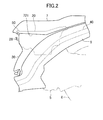
- Fig. 2 is a side view showing major elements of the two-wheeled motor vehicle 1 with the seat 7 closed.
- Figs. 3A and 3B are a side view and a plan view showing major elements of the two-wheeled motor vehicle 1 with the seat 7 opened.
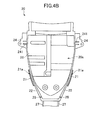
- Figs. 4A and 4B are a side view and a plan view of a storage box 20.
- Figs. 5A and 5B are a side view and a front view of a cover 30.
- Fig. 6 is a cross sectional view of the storage box 20 and the cover 30.
- the directions forward (in front of, and so forth), rearward (behind, at the back, and so forth), upward (higher, above, and so forth), downward (lower, below, and so forth), leftward, and rightward respectively refer to the directions forward (in front of, and so forth), rearward (behind, at the back, and so forth), upward (higher, above, and so forth), downward (lower, below, and so forth), leftward, and rightward viewed from a driver striding on the seat 7 with his/her face toward the handle 4.
- the arrow F in Fig. 1 indicates the forward direction.
- the front wheel 2 of the two-wheeled motor vehicle 1 is supported by the lower end of the front fork 3.
- the front fork 3 is supported so as to swing left and right by a steering shaft (not shown) supported at the foremost part of the vehicle body frame.
- a handle 4 is connected to the upper part of the front fork 3.
- the two-wheeled motor vehicle 1 has an engine unit 5 mounted on a rear part thereof.
- the engine unit 5 includes a crankcase 5a, a cylinder 5b, and a transmission case 5c.
- the transmission case 5c stores a transmission mechanism for transmitting rotation of the crank shaft provided to the crankcase 5a via a belt, a chain, or the like to the rear wheel 6.
- the engine unit 5 can swing up and down relative to the vehicle body frame together with the rear wheel 6.
- a seat 7 is placed above the engine unit 5. There is a space S between the front wheel 2 and the seat 7. A step board 8 is provided under the space S for a rider to put his/her foot on.
- a storage box 20 is placed above the engine unit 5 under the seat 7, and a cover 30 is placed on the outer lateral side of the storage box 20.
- the storage box 20 is placed between a pair of left and right main frames 40 extending up-rearward of the vehicle body frame, and supported by these main frames 40.
- brackets 24 formed on a rear part of the storage box 20 are attached to brackets (not shown) formed on the main frames 40.
- Side covers 9 are placed on the outer lateral side of the main frames 40 respectively.
- the seat 7 can swing by means of a hinge mechanism 50 provided to the front end of the seat 7 and the front end of the storage box 20. Specifically, the seat 7 swings such that the rear part thereof moves up and down to thereby open and close the opening defined by the upper edge 22 of the storage box 20.
- Fig. 2 shows the seat 7 closing the opening of the storage box 20.
- Figs. 3A and 3B show the seat 7 positioned such that the opening of the storage box 20 is left open.
- the hinge mechanism 50 comprises a shaft 52, a pair of hinges 78 provided to the seat 7 so as to rotate relative to the shaft 52, and a pair of hinges 27 provided to the storage box 20 so as to rotate relative to the shaft 52.
- the storage box 20 has a substantially box-like shape that becomes narrower as it goes forward, and has a storage space 20a open upward.
- the storage box 20 has a battery case 25 projecting downward for storing a battery (not shown).
- the storage space 20a of the storage box 20 and the storage space of the battery case 25 are separated by a roof 26.
- the brackets 24 that spread outer-sideward are formed on a rear part of the outer lateral surface 23 of the storage box 20, and a plurality of ribs 241 are formed above and below the brackets 24, extending in the up-down direction.
- Hinges 27, being a part of the hinge mechanism 50, are formed to the front end of the storage box 20, and a hook 28 is formed below the hinges 27.
- Projections 29 projecting upward are formed behind the hinges 27 to abut on the bottom surface of the seat 7 when the seat 7 is closed.
- Another projection 21 is formed on the outer lateral surface 23 of the storage box 20 at a position lower than the upper edge 22, extending substantially parallel to the upper edge 22.
- the projection 21 is crooked upward to thereby define a groove 21a between itself and the outer lateral surface 23.
- a flange spreading outer-sideward is not formed on the upper edge 22 of the storage box 20. That is, the upper part 232 of the outer lateral surface 23 of the storage box 20 above the projection 21 is formed as a flat surface up to the upper edge 22. In other words, the thickness of the part of the lateral wall of the storage box 20 above the projection 21 is substantially uniform. As no flange is formed, the projection 21 can be seen in a plan view of the storage box 20 (see Fig. 4B ).
- the cover 30 includes an upper part 32 covering the front and lateral of the storage box 20, a lower part 34 extending downward from the upper part 32 and covering the front of the engine unit 5, and a pair of rear parts 36 extending up-rearward from the upper part 32.
- On the inner lateral surface of the upper part 32 a plurality of engaging parts 31 are formed at positions lower than the upper edge 37, projecting inner-sideward and downward. These engaging parts 31 are engaged with the projections 21 formed on the storage box 20.
- an engaging part 39 for engagement with the side cover 9 is formed on the edge of the lower part 34, and an engaging part 38 for engagement with the storage box 20 is formed on an end part of the rear part 36.
- a cover 30 having a part to be placed at least beside the storage box 20 is usable, and the shape shown in Figs. 5A and 5B is not limiting.
- a plurality of covers may be separately placed to the left and right, respectively, of the storage box 20.
- the lateral part 72 of the bottom surface of the seat 7 is bent downward so as to be opposed to the outer lateral surface 23 of the storage box 20.
- the lateral part 72 of the bottom surface of the seat 7 extends diagonally so as to go farther away from the lateral surface 23 of the storage box 20 as it goes downward.
- the projection 21 formed on the outer lateral surface 23 of the storage box 20 is positioned lower than the upper edge 22 of the storage box 20.
- the projection 21 is positioned as such, it is possible to have the outer lateral surface 23 of the storage box 20 positioned close to the lateral part 72 of the bottom surface of the seat 7. This can increase the capacity of the storage box 20 while reducing increase of the width of the seat 7.
- the projection 21 is positioned lower than the lower edge 721 of the lateral part of the seat 7 in this embodiment, this is not limiting, and the projection 21 may be positioned higher than the lower edge 721.
- the upper edge 37 of the cover 30 is positioned, in the side view, higher than the lower edge 721 of the lateral part of the seat 7 but lower than the upper edge 22 of the storage box 20. Therefore, with the seat 7 closed, the storage box 20 can be hardly seen in the side view (see Fig. 2 ).
- the projection 21 positioned lower than the upper edge 22 overlaps the upper edge 37 of the cover 30 in a plan view. Therefore, it is possible to have the engine unit 5 or the like placed below be hardly seen through the space between the outer lateral surface 23 of the storage box 20 and the upper edge 37 of the cover 30 and to prevent introduction of foreign matters and a hand through the space (see Fig. 3B ).
- the seat 7 that swings up and down to thereby open and close the opening of the storage box 20 is provided, and the lateral part 72 of the bottom surface of the seat 7 is bent downward and opposed to the lateral surface 23 of the storage box 20 so as to go farther away from the lateral surface 23 as it goes downward. That is, the interval between the lateral part 72 of the bottom surface of the seat 7 and the lateral surface 23 of the storage box 20 becomes wider as it goes downward.
- the projection 21 is formed at a position lower than the upper edge 22, rather than providing a flange on the upper edge 22 of the storage box 20.
- the engaging part 31 formed on the inner lateral surface of the cover 30 is inserted into the groove 21a defined between the outer lateral surface 23 of the storage box 20 and the projection 21, and engaged with the projection 21. Therefore, it is possible to reduce the space between the outer lateral surface 23 of the storage box 20 and the upper edge 37 of the cover 30 (see Fig. 6 ).
- the projection 21 extends along the upper edge 37 of the cover 30. Therefore, it is possible to reduce the space between the outer lateral surface 23 of the storage box 20 and the upper edge 37 of the cover 30 over a wide range (see Fig. 3B ).
- the upper edge 37 of the cover 30 can be seen in a plan view. Therefore, it is possible to have the engine unit 5 and the like placed below be hardly seen through the space between the outer lateral surface 23 of the storage box 20 and the upper edge 37 of the cover 30 (see Fig. 3B ).
- the upper edge 37 of the cover 30 has an inner flange 372 projecting toward the outer lateral surface 23 of the storage box 20. This enables further reduction of the space between the outer lateral surface 23 of the storage box 20 and the upper edge 37 of the cover 30 (see Fig. 6 ). Note that, however, the inner flange 372 is not mandatory.
- the pair of hinges 78 formed on the seat 7 are positioned more outer-sideward than the pair of hinges 27 formed on the storage box 20.
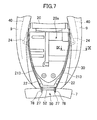
- Fig. 7 is a plan view showing major elements of the two-wheeled motor vehicle 1 with the seat 7 opened.
- Fig. 8 is a plan view of the storage box 20.
- Fig. 9 is a cross sectional view of the storage box 20 and the cover 30. Note that a member identical to that described in the first embodiment is given an identical number, and will not be described in detail again here.
- a projection 213 is formed at a position lower than the upper edge 22, extending substantially parallel to the upper edge 22 in the range between the front end and the rear end of the outer lateral surface 23.
- the projection 213 is positioned higher than the lower edge 721 of the lateral part of the seat 7.
- the projection 213 overlaps the upper edge 37 of the cover 30, and extends above and along the upper edge 37 of the cover 30.
- the projection 213 of the storage box 20 can be seen in a plan view when the seat 7 is so positioned that the opening of the storage box 20 is left open, it is possible to have the engine unit 5 and the like placed below be hardly seen through the space between the outer lateral surface 23 of the storage box 20 and the upper edge 37 of the cover 30 and to prevent introduction of foreign matters and a hand through the space.
- the upper edge 37 of the cover 30 has an inner flange 372 projecting toward the outer lateral surface 23 of the storage box 20. This enables further reduction of the space between the outer lateral surface 23 of the storage box 20 and the upper edge 37 of the cover 30 (see Fig. 9 ). Note that, however, the inner flange 372 is not mandatory.
- a dent part 24a that is dented inner-sideward is formed below the projection 29 on the outer lateral surface 23 of the storage box 20.
- a plurality of ribs 243 extending in the up-down direction are formed inside the dent part 24a.
- the ribs 241, 243 are formed at positions lower than the projection 213 as described above, it is possible to have the ribs 241, 243 be hardly seen through the space between the outer lateral surface 23 of the storage box 20 and the upper edge 37 of the cover 30, and also to improve rigidity of the storage box 20.
Landscapes
- Engineering & Computer Science (AREA)
- Mechanical Engineering (AREA)
- Vehicle Step Arrangements And Article Storage (AREA)
- Lock And Its Accessories (AREA)
- Motorcycle And Bicycle Frame (AREA)
- Chair Legs, Seat Parts, And Backrests (AREA)
Abstract
Description
- The present invention relates to a two-wheeled motor vehicle, and in particular to a structure of a storage box placed below the seat and that of a cover placed beside the storage box.
- Japanese Patent Laid-open Publication No.
2008-155905 - According to the related art, it is necessary to ensure some space between the outer edge of the flange spreading outward and the inner surface of the seat. Therefore, when the lateral wall of the storage box is formed at a position more outward in order to ensure an increased capacity of the storage box, widening the seat width is inevitable.
- Meanwhile, in a structure without a flange formed on the upper edge of the storage box, a member, such as an engine or the like, placed below the storage box may likely be seen through the space between the storage box and the cover placed beside the storage box, and foreign matters and a hand may be allowed to be introduced through the space.
- The present invention has been conceived in view of the above described situation, and a main object thereof is to provide a two-wheeled motor vehicle capable of ensuring an increased capacity of the storage box, while reducing increase of the seat width, and moreover, to have a member placed below be hardly seen through the space between the storage box and the cover, and preventing introduction of foreign matters and a hand through the space.
- In order to achieve the above described object, according to one aspect of the present invention, there is provided a two-wheeled motor vehicle, comprising a vehicle body frame, a storage box supported by the vehicle body frame, a seat placed above the storage box, being capable of opening and closing an opening defined by an upper edge of the storage box, and a cover placed beside the storage box. A lateral part of a bottom surface of the seat is bent downward and opposed to a lateral surface of the storage box so as to go farther away from the lateral surface of the storage box as it goes downward. An upper edge of the cover is positioned, in a side view, higher than a lower edge of a lateral part of the seat lower than the upper edge of the storage box. The lateral surface of the storage box has a projection formed thereon at a position lower than the upper edge thereof, the projection overlapping the upper edge of the cover in a plan view.
- According to the present invention, no flange that spreads outward is formed on the upper edge of the storage box, and instead, a projection is formed at a position lower than the upper edge of the storage box, the position having a relatively large space with respect to the seat. This allows the lateral wall of the storage box be positioned close to the seat. Therefore, it is possible to increase the capacity of the storage box while reducing increase of the seat width. Further, the projection formed can make a member below be hardly seen from the space between the storage box and the cover, and introduction of foreign matters and a hand through the space can be prevented.
-
Fig. 1 is a side view of a two-wheeled motor vehicle according to one embodiment of the present invention; -
Fig. 2 is a side view showing major elements of the two-wheeled motor vehicle with the seat closed; -
Fig. 3A is a side view showing major elements of the two-wheeled motor vehicle with the seat opened; -
Fig. 3B is a plan view showing major elements of the two-wheeled motor vehicle with the seat opened; -
Fig. 4A is a side view of a storage box; -
Fig. 4B is a plan view of the storage box; -
Fig. 5A is a side view of a cover; -
Fig. 5B is a front view of the cover; -
Fig. 6 is a cross sectional view of the storage box and the cover; -
Fig. 7 is a plan view showing maj or elements of the two-wheeled motor vehicle with the seat opened; -
Fig. 8 is a plan view of the storage box; and -
Fig. 9 is a cross sectional view of the storage box and the cover. - An embodiment of a two-wheeled motor vehicle according to the present invention will be described with reference to the accompanying drawings.
-
Fig. 1 is a side view of a two-wheeled motor vehicle 1.Fig. 2 is a side view showing major elements of the two-wheeled motor vehicle 1 with theseat 7 closed.Figs. 3A and3B are a side view and a plan view showing major elements of the two-wheeled motor vehicle 1 with theseat 7 opened.Figs. 4A and4B are a side view and a plan view of astorage box 20.Figs. 5A and5B are a side view and a front view of acover 30.Fig. 6 is a cross sectional view of thestorage box 20 and thecover 30. - In the description below, the directions forward (in front of, and so forth), rearward (behind, at the back, and so forth), upward (higher, above, and so forth), downward (lower, below, and so forth), leftward, and rightward respectively refer to the directions forward (in front of, and so forth), rearward (behind, at the back, and so forth), upward (higher, above, and so forth), downward (lower, below, and so forth), leftward, and rightward viewed from a driver striding on the
seat 7 with his/her face toward thehandle 4. The arrow F inFig. 1 indicates the forward direction. - As shown in
Fig. 1 , thefront wheel 2 of the two-wheeled motor vehicle 1 is supported by the lower end of the front fork 3. The front fork 3 is supported so as to swing left and right by a steering shaft (not shown) supported at the foremost part of the vehicle body frame. Ahandle 4 is connected to the upper part of the front fork 3. - The two-
wheeled motor vehicle 1 has anengine unit 5 mounted on a rear part thereof. Theengine unit 5 includes acrankcase 5a, acylinder 5b, and atransmission case 5c. Thetransmission case 5c stores a transmission mechanism for transmitting rotation of the crank shaft provided to thecrankcase 5a via a belt, a chain, or the like to therear wheel 6. Theengine unit 5 can swing up and down relative to the vehicle body frame together with therear wheel 6. - A
seat 7 is placed above theengine unit 5. There is a space S between thefront wheel 2 and theseat 7. Astep board 8 is provided under the space S for a rider to put his/her foot on. - As shown in
Figs. 2 to 3B , astorage box 20 is placed above theengine unit 5 under theseat 7, and acover 30 is placed on the outer lateral side of thestorage box 20. Thestorage box 20 is placed between a pair of left and rightmain frames 40 extending up-rearward of the vehicle body frame, and supported by thesemain frames 40. Specifically,brackets 24 formed on a rear part of thestorage box 20 are attached to brackets (not shown) formed on themain frames 40.Side covers 9 are placed on the outer lateral side of themain frames 40 respectively. - The
seat 7 can swing by means of ahinge mechanism 50 provided to the front end of theseat 7 and the front end of thestorage box 20. Specifically, theseat 7 swings such that the rear part thereof moves up and down to thereby open and close the opening defined by theupper edge 22 of thestorage box 20.Fig. 2 shows theseat 7 closing the opening of thestorage box 20.Figs. 3A and3B show theseat 7 positioned such that the opening of thestorage box 20 is left open. Thehinge mechanism 50 comprises ashaft 52, a pair ofhinges 78 provided to theseat 7 so as to rotate relative to theshaft 52, and a pair ofhinges 27 provided to thestorage box 20 so as to rotate relative to theshaft 52. - As shown in
Figs. 4A andFig. 4B , thestorage box 20 has a substantially box-like shape that becomes narrower as it goes forward, and has astorage space 20a open upward. Thestorage box 20 has abattery case 25 projecting downward for storing a battery (not shown). Thestorage space 20a of thestorage box 20 and the storage space of thebattery case 25 are separated by aroof 26. - The
brackets 24 that spread outer-sideward are formed on a rear part of the outerlateral surface 23 of thestorage box 20, and a plurality ofribs 241 are formed above and below thebrackets 24, extending in the up-down direction. Hinges 27, being a part of thehinge mechanism 50, are formed to the front end of thestorage box 20, and ahook 28 is formed below the hinges 27.Projections 29 projecting upward are formed behind thehinges 27 to abut on the bottom surface of theseat 7 when theseat 7 is closed. - Another
projection 21 is formed on the outerlateral surface 23 of thestorage box 20 at a position lower than theupper edge 22, extending substantially parallel to theupper edge 22. Theprojection 21 is crooked upward to thereby define agroove 21a between itself and the outerlateral surface 23. Note that a flange spreading outer-sideward is not formed on theupper edge 22 of thestorage box 20. That is, theupper part 232 of the outerlateral surface 23 of thestorage box 20 above theprojection 21 is formed as a flat surface up to theupper edge 22. In other words, the thickness of the part of the lateral wall of thestorage box 20 above theprojection 21 is substantially uniform. As no flange is formed, theprojection 21 can be seen in a plan view of the storage box 20 (seeFig. 4B ). - As shown in
Figs. 5A and5B , thecover 30 includes anupper part 32 covering the front and lateral of thestorage box 20, alower part 34 extending downward from theupper part 32 and covering the front of theengine unit 5, and a pair ofrear parts 36 extending up-rearward from theupper part 32. On the inner lateral surface of theupper part 32, a plurality of engagingparts 31 are formed at positions lower than theupper edge 37, projecting inner-sideward and downward. These engagingparts 31 are engaged with theprojections 21 formed on thestorage box 20. Further, an engagingpart 39 for engagement with theside cover 9 is formed on the edge of thelower part 34, and anengaging part 38 for engagement with thestorage box 20 is formed on an end part of therear part 36. Note that acover 30 having a part to be placed at least beside thestorage box 20 is usable, and the shape shown inFigs. 5A and5B is not limiting. For example, a plurality of covers may be separately placed to the left and right, respectively, of thestorage box 20. - As shown in
Fig. 6 , thelateral part 72 of the bottom surface of theseat 7 is bent downward so as to be opposed to the outerlateral surface 23 of thestorage box 20. Thelateral part 72 of the bottom surface of theseat 7 extends diagonally so as to go farther away from thelateral surface 23 of thestorage box 20 as it goes downward. Theprojection 21 formed on the outerlateral surface 23 of thestorage box 20 is positioned lower than theupper edge 22 of thestorage box 20. When theprojection 21 is positioned as such, it is possible to have the outerlateral surface 23 of thestorage box 20 positioned close to thelateral part 72 of the bottom surface of theseat 7. This can increase the capacity of thestorage box 20 while reducing increase of the width of theseat 7. Note that although theprojection 21 is positioned lower than thelower edge 721 of the lateral part of theseat 7 in this embodiment, this is not limiting, and theprojection 21 may be positioned higher than thelower edge 721. - With the opening of the
storage box 20 closed by theseat 7, theupper edge 37 of thecover 30 is positioned, in the side view, higher than thelower edge 721 of the lateral part of theseat 7 but lower than theupper edge 22 of thestorage box 20. Therefore, with theseat 7 closed, thestorage box 20 can be hardly seen in the side view (seeFig. 2 ). - The
projection 21 positioned lower than theupper edge 22 overlaps theupper edge 37 of thecover 30 in a plan view. Therefore, it is possible to have theengine unit 5 or the like placed below be hardly seen through the space between the outerlateral surface 23 of thestorage box 20 and theupper edge 37 of thecover 30 and to prevent introduction of foreign matters and a hand through the space (seeFig. 3B ). - In this embodiment, the
seat 7 that swings up and down to thereby open and close the opening of thestorage box 20 is provided, and thelateral part 72 of the bottom surface of theseat 7 is bent downward and opposed to thelateral surface 23 of thestorage box 20 so as to go farther away from thelateral surface 23 as it goes downward. That is, the interval between thelateral part 72 of the bottom surface of theseat 7 and thelateral surface 23 of thestorage box 20 becomes wider as it goes downward. In this embodiment, in order to utilize the widening interval, theprojection 21 is formed at a position lower than theupper edge 22, rather than providing a flange on theupper edge 22 of thestorage box 20. With the above, it is possible to obtain both effects of increasing the capacity of thestorage box 20 and of having a member placed below be hardly seen and preventing introduction of foreign matters and a hand through the space between thestorage box 20 and thecover 30. - Further, the engaging
part 31 formed on the inner lateral surface of thecover 30 is inserted into thegroove 21a defined between the outerlateral surface 23 of thestorage box 20 and theprojection 21, and engaged with theprojection 21. Therefore, it is possible to reduce the space between the outerlateral surface 23 of thestorage box 20 and theupper edge 37 of the cover 30 (seeFig. 6 ). - Further, below the
upper edge 37 of thecover 30, theprojection 21 extends along theupper edge 37 of thecover 30. Therefore, it is possible to reduce the space between the outerlateral surface 23 of thestorage box 20 and theupper edge 37 of thecover 30 over a wide range (seeFig. 3B ). - Further, when the
seat 7 is so positioned that the opening of thestorage box 20 is left open, theupper edge 37 of thecover 30 can be seen in a plan view. Therefore, it is possible to have theengine unit 5 and the like placed below be hardly seen through the space between the outerlateral surface 23 of thestorage box 20 and theupper edge 37 of the cover 30 (seeFig. 3B ). - Further, the
upper edge 37 of thecover 30 has aninner flange 372 projecting toward the outerlateral surface 23 of thestorage box 20. This enables further reduction of the space between the outerlateral surface 23 of thestorage box 20 and theupper edge 37 of the cover 30 (seeFig. 6 ). Note that, however, theinner flange 372 is not mandatory. - Further, the pair of
hinges 78 formed on theseat 7 are positioned more outer-sideward than the pair ofhinges 27 formed on thestorage box 20. With the above, when a force in the left-right direction is applied to theseat 7, the force being transmitted via thehinges storage box 20 can be reduced, and thus deformation of thestorage box 20 can be reduced (seeFig. 3B ). -
Fig. 7 is a plan view showing major elements of the two-wheeledmotor vehicle 1 with theseat 7 opened.Fig. 8 is a plan view of thestorage box 20.Fig. 9 is a cross sectional view of thestorage box 20 and thecover 30. Note that a member identical to that described in the first embodiment is given an identical number, and will not be described in detail again here. - As shown in
Figs. 7 to 9 , on the outerlateral surface 23 of thestorage box 20, aprojection 213 is formed at a position lower than theupper edge 22, extending substantially parallel to theupper edge 22 in the range between the front end and the rear end of the outerlateral surface 23. Theprojection 213 is positioned higher than thelower edge 721 of the lateral part of theseat 7. With theprojection 213 positioned as such, it is possible to have the outerlateral surface 23 of thestorage box 20 be close to thelateral part 72 of the bottom surface of theseat 7. Therefore, it is possible to increase the capacity of thestorage box 20 while reducing increase of the width of theseat 7. - Further, in a plan view, the
projection 213 overlaps theupper edge 37 of thecover 30, and extends above and along theupper edge 37 of thecover 30. As theprojection 213 of thestorage box 20 can be seen in a plan view when theseat 7 is so positioned that the opening of thestorage box 20 is left open, it is possible to have theengine unit 5 and the like placed below be hardly seen through the space between the outerlateral surface 23 of thestorage box 20 and theupper edge 37 of thecover 30 and to prevent introduction of foreign matters and a hand through the space. - Further, the
upper edge 37 of thecover 30 has aninner flange 372 projecting toward the outerlateral surface 23 of thestorage box 20. This enables further reduction of the space between the outerlateral surface 23 of thestorage box 20 and theupper edge 37 of the cover 30 (seeFig. 9 ). Note that, however, theinner flange 372 is not mandatory. - Further, a
dent part 24a that is dented inner-sideward is formed below theprojection 29 on the outerlateral surface 23 of thestorage box 20. A plurality ofribs 243 extending in the up-down direction are formed inside thedent part 24a. As theribs projection 213 as described above, it is possible to have theribs lateral surface 23 of thestorage box 20 and theupper edge 37 of thecover 30, and also to improve rigidity of thestorage box 20. - Although an embodiment of the present invention has been described above, the present invention is not limited to the above described embodiment, and obviously, various modified embodiments are possible for a person skilled in the art.
Claims (10)
- A two-wheeled motor vehicle, comprising:a vehicle body frame;a storage box supported by the vehicle body frame;a seat placed above the storage box, being capable of opening and closing an opening defined by an upper edge of the storage box; anda cover placed beside the storage box,wherein
a lateral part of a bottom surface of the seat is bent downward, and opposed to a lateral surface of the storage box so as to go farther away from the lateral surface of the storage box as it goes downward,
an upper edge of the cover is positioned, in a side view, higher than a lower edge of a lateral part of the seat lower than the upper edge of the storage box, and
the lateral surface of the storage box has a projection formed thereon at a position lower than the upper edge thereof, the projection overlapping the upper edge of the cover in a plan view, in which a part of the lateral surface above the projection is formed as a flat surface up to the upper edge of the storage box. - The two-wheeled motor vehicle according to claim 1, wherein the projection is an engagement portion for engagement with an engagement portion formed on an inner surface of the cover.
- The two-wheeled motor vehicle according to claim 1 or 2, wherein the projection extends below and along the upper edge of the cover.
- The two-wheeled motor vehicle according to any one of claims 1 to 3, wherein when the seat is positioned leaving the opening of the storage box open, the upper edge of the cover is seen in a plan view.
- The two-wheeled motor vehicle according to claim 1, wherein the projection extends above and along the upper edge of the cover.
- The two-wheeled motor vehicle according to claim 5, wherein when the seat is positioned leaving the opening of the storage box open, the projection is seen in a plan view.
- The two-wheeled motor vehicle according to claim 1, wherein the upper edge of the cover has an inside flange projecting toward the lateral surface of the storage box.
- The two-wheeled motor vehicle according to any one of claims 1 to 7, wherein the seat is able to swing by means of a hinge mechanism provided to a front end of the seat and a front end of the storage box.
- The two-wheeled motor vehicle according to claim 8, wherein
the hinge mechanism includes a shaft, a pair of hinges attached to the seat so as to swing relative to the shaft, and a pair of hinges attached to the storage box so as to swing relative to the shaft, and
the pair of hinges attached to the seat are positioned more outward than the pair of hinges attached to the storage box. - The two-wheeled motor vehicle according to any one of claims 1 to 9, wherein a rib extending in an up-down direction is formed on a lateral wall of the storage box at a position lower than the projection.
Applications Claiming Priority (1)
| Application Number | Priority Date | Filing Date | Title |
|---|---|---|---|
| JP2011152889A JP2013018349A (en) | 2011-07-11 | 2011-07-11 | Motorcycle |
Publications (3)
| Publication Number | Publication Date |
|---|---|
| EP2546133A2 true EP2546133A2 (en) | 2013-01-16 |
| EP2546133A3 EP2546133A3 (en) | 2014-05-21 |
| EP2546133B1 EP2546133B1 (en) | 2018-09-05 |
Family
ID=46458274
Family Applications (1)
| Application Number | Title | Priority Date | Filing Date |
|---|---|---|---|
| EP12174759.6A Active EP2546133B1 (en) | 2011-07-11 | 2012-07-03 | Two-wheeled motor vehicle |
Country Status (2)
| Country | Link |
|---|---|
| EP (1) | EP2546133B1 (en) |
| JP (1) | JP2013018349A (en) |
Families Citing this family (1)
| Publication number | Priority date | Publication date | Assignee | Title |
|---|---|---|---|---|
| JP2018131146A (en) | 2017-02-17 | 2018-08-23 | ヤマハ発動機株式会社 | Saddle riding vehicle |
Citations (1)
| Publication number | Priority date | Publication date | Assignee | Title |
|---|---|---|---|---|
| JP2008155905A (en) | 2006-11-29 | 2008-07-10 | Honda Motor Co Ltd | Saddle riding |
Family Cites Families (4)
| Publication number | Priority date | Publication date | Assignee | Title |
|---|---|---|---|---|
| JP3397274B2 (en) * | 1995-06-29 | 2003-04-14 | ヤマハ発動機株式会社 | Body side processing structure of motorcycle |
| JP3716063B2 (en) * | 1996-12-04 | 2005-11-16 | ヤマハ発動機株式会社 | Storage box for motorcycle |
| JP4145545B2 (en) * | 2002-03-29 | 2008-09-03 | 本田技研工業株式会社 | Cargo illumination device for motorcycles |
| JP4031974B2 (en) * | 2002-07-15 | 2008-01-09 | 本田技研工業株式会社 | Motorcycle seat mounting structure |
-
2011
- 2011-07-11 JP JP2011152889A patent/JP2013018349A/en not_active Withdrawn
-
2012
- 2012-07-03 EP EP12174759.6A patent/EP2546133B1/en active Active
Patent Citations (1)
| Publication number | Priority date | Publication date | Assignee | Title |
|---|---|---|---|---|
| JP2008155905A (en) | 2006-11-29 | 2008-07-10 | Honda Motor Co Ltd | Saddle riding |
Also Published As
| Publication number | Publication date |
|---|---|
| EP2546133B1 (en) | 2018-09-05 |
| EP2546133A3 (en) | 2014-05-21 |
| JP2013018349A (en) | 2013-01-31 |
Similar Documents
| Publication | Publication Date | Title |
|---|---|---|
| EP2457813B1 (en) | Inner rack structure for saddle-ride type vehicle | |
| JP6380488B2 (en) | Vehicle door | |
| JP2014210549A (en) | Motorcycle | |
| CN104955721B (en) | electric assist bike | |
| EP2327615A3 (en) | Scooter-type vehicle | |
| EP3061679B1 (en) | Rear structure for saddle-ride type vehicle | |
| EP3225517A2 (en) | Rear portion structure of saddle-ride type vehicle | |
| JP2006036013A (en) | Motorcycle | |
| JP7340686B2 (en) | inner box structure | |
| EP2546133B1 (en) | Two-wheeled motor vehicle | |
| EP2647558A1 (en) | Straddle type vehicle | |
| JP2016107929A (en) | Saddle-riding type vehicle | |
| WO2014181651A1 (en) | Motorcycle | |
| EP2221220B1 (en) | Motorcycle | |
| JP2009046064A (en) | console | |
| JP4431026B2 (en) | Vehicle storage structure | |
| JP6133675B2 (en) | Seat opening / closing structure for saddle-ride type vehicles | |
| EP2546129B1 (en) | Two-wheeled motor vehicle | |
| JP6063648B2 (en) | Electrical component mounting structure | |
| JP6118216B2 (en) | Motorcycle | |
| JP2004306750A (en) | Step board for saddle riding type vehicles | |
| EP3000702B1 (en) | Saddle-riding type vehicle | |
| JP4645226B2 (en) | Jack arrangement structure of vehicle | |
| JP7177766B2 (en) | Saddle type vehicle storage structure | |
| JP2010089580A (en) | Motorcycle |
Legal Events
| Date | Code | Title | Description |
|---|---|---|---|
| PUAI | Public reference made under article 153(3) epc to a published international application that has entered the european phase |
Free format text: ORIGINAL CODE: 0009012 |
|
| AK | Designated contracting states |
Kind code of ref document: A2 Designated state(s): AL AT BE BG CH CY CZ DE DK EE ES FI FR GB GR HR HU IE IS IT LI LT LU LV MC MK MT NL NO PL PT RO RS SE SI SK SM TR |
|
| AX | Request for extension of the european patent |
Extension state: BA ME |
|
| PUAL | Search report despatched |
Free format text: ORIGINAL CODE: 0009013 |
|
| AK | Designated contracting states |
Kind code of ref document: A3 Designated state(s): AL AT BE BG CH CY CZ DE DK EE ES FI FR GB GR HR HU IE IS IT LI LT LU LV MC MK MT NL NO PL PT RO RS SE SI SK SM TR |
|
| AX | Request for extension of the european patent |
Extension state: BA ME |
|
| RIC1 | Information provided on ipc code assigned before grant |
Ipc: B62K 19/46 20060101AFI20140416BHEP |
|
| 17P | Request for examination filed |
Effective date: 20141105 |
|
| RBV | Designated contracting states (corrected) |
Designated state(s): AL AT BE BG CH CY CZ DE DK EE ES FI FR GB GR HR HU IE IS IT LI LT LU LV MC MK MT NL NO PL PT RO RS SE SI SK SM TR |
|
| 17Q | First examination report despatched |
Effective date: 20150220 |
|
| STAA | Information on the status of an ep patent application or granted ep patent |
Free format text: STATUS: EXAMINATION IS IN PROGRESS |
|
| GRAP | Despatch of communication of intention to grant a patent |
Free format text: ORIGINAL CODE: EPIDOSNIGR1 |
|
| STAA | Information on the status of an ep patent application or granted ep patent |
Free format text: STATUS: GRANT OF PATENT IS INTENDED |
|
| INTG | Intention to grant announced |
Effective date: 20180322 |
|
| RIN1 | Information on inventor provided before grant (corrected) |
Inventor name: KODAMA, AYUMU |
|
| GRAS | Grant fee paid |
Free format text: ORIGINAL CODE: EPIDOSNIGR3 |
|
| GRAA | (expected) grant |
Free format text: ORIGINAL CODE: 0009210 |
|
| STAA | Information on the status of an ep patent application or granted ep patent |
Free format text: STATUS: THE PATENT HAS BEEN GRANTED |
|
| AK | Designated contracting states |
Kind code of ref document: B1 Designated state(s): AL AT BE BG CH CY CZ DE DK EE ES FI FR GB GR HR HU IE IS IT LI LT LU LV MC MK MT NL NO PL PT RO RS SE SI SK SM TR |
|
| REG | Reference to a national code |
Ref country code: GB Ref legal event code: FG4D |
|
| REG | Reference to a national code |
Ref country code: CH Ref legal event code: EP |
|
| REG | Reference to a national code |
Ref country code: AT Ref legal event code: REF Ref document number: 1037470 Country of ref document: AT Kind code of ref document: T Effective date: 20180915 |
|
| REG | Reference to a national code |
Ref country code: DE Ref legal event code: R096 Ref document number: 602012050572 Country of ref document: DE |
|
| REG | Reference to a national code |
Ref country code: IE Ref legal event code: FG4D |
|
| REG | Reference to a national code |
Ref country code: NL Ref legal event code: MP Effective date: 20180905 |
|
| REG | Reference to a national code |
Ref country code: LT Ref legal event code: MG4D |
|
| PG25 | Lapsed in a contracting state [announced via postgrant information from national office to epo] |
Ref country code: NO Free format text: LAPSE BECAUSE OF FAILURE TO SUBMIT A TRANSLATION OF THE DESCRIPTION OR TO PAY THE FEE WITHIN THE PRESCRIBED TIME-LIMIT Effective date: 20181205 Ref country code: GR Free format text: LAPSE BECAUSE OF FAILURE TO SUBMIT A TRANSLATION OF THE DESCRIPTION OR TO PAY THE FEE WITHIN THE PRESCRIBED TIME-LIMIT Effective date: 20181206 Ref country code: BG Free format text: LAPSE BECAUSE OF FAILURE TO SUBMIT A TRANSLATION OF THE DESCRIPTION OR TO PAY THE FEE WITHIN THE PRESCRIBED TIME-LIMIT Effective date: 20181205 Ref country code: LT Free format text: LAPSE BECAUSE OF FAILURE TO SUBMIT A TRANSLATION OF THE DESCRIPTION OR TO PAY THE FEE WITHIN THE PRESCRIBED TIME-LIMIT Effective date: 20180905 Ref country code: SE Free format text: LAPSE BECAUSE OF FAILURE TO SUBMIT A TRANSLATION OF THE DESCRIPTION OR TO PAY THE FEE WITHIN THE PRESCRIBED TIME-LIMIT Effective date: 20180905 Ref country code: RS Free format text: LAPSE BECAUSE OF FAILURE TO SUBMIT A TRANSLATION OF THE DESCRIPTION OR TO PAY THE FEE WITHIN THE PRESCRIBED TIME-LIMIT Effective date: 20180905 Ref country code: FI Free format text: LAPSE BECAUSE OF FAILURE TO SUBMIT A TRANSLATION OF THE DESCRIPTION OR TO PAY THE FEE WITHIN THE PRESCRIBED TIME-LIMIT Effective date: 20180905 |
|
| REG | Reference to a national code |
Ref country code: AT Ref legal event code: MK05 Ref document number: 1037470 Country of ref document: AT Kind code of ref document: T Effective date: 20180905 |
|
| PG25 | Lapsed in a contracting state [announced via postgrant information from national office to epo] |
Ref country code: AL Free format text: LAPSE BECAUSE OF FAILURE TO SUBMIT A TRANSLATION OF THE DESCRIPTION OR TO PAY THE FEE WITHIN THE PRESCRIBED TIME-LIMIT Effective date: 20180905 Ref country code: LV Free format text: LAPSE BECAUSE OF FAILURE TO SUBMIT A TRANSLATION OF THE DESCRIPTION OR TO PAY THE FEE WITHIN THE PRESCRIBED TIME-LIMIT Effective date: 20180905 Ref country code: HR Free format text: LAPSE BECAUSE OF FAILURE TO SUBMIT A TRANSLATION OF THE DESCRIPTION OR TO PAY THE FEE WITHIN THE PRESCRIBED TIME-LIMIT Effective date: 20180905 |
|
| PG25 | Lapsed in a contracting state [announced via postgrant information from national office to epo] |
Ref country code: PL Free format text: LAPSE BECAUSE OF FAILURE TO SUBMIT A TRANSLATION OF THE DESCRIPTION OR TO PAY THE FEE WITHIN THE PRESCRIBED TIME-LIMIT Effective date: 20180905 Ref country code: AT Free format text: LAPSE BECAUSE OF FAILURE TO SUBMIT A TRANSLATION OF THE DESCRIPTION OR TO PAY THE FEE WITHIN THE PRESCRIBED TIME-LIMIT Effective date: 20180905 Ref country code: IS Free format text: LAPSE BECAUSE OF FAILURE TO SUBMIT A TRANSLATION OF THE DESCRIPTION OR TO PAY THE FEE WITHIN THE PRESCRIBED TIME-LIMIT Effective date: 20190105 Ref country code: EE Free format text: LAPSE BECAUSE OF FAILURE TO SUBMIT A TRANSLATION OF THE DESCRIPTION OR TO PAY THE FEE WITHIN THE PRESCRIBED TIME-LIMIT Effective date: 20180905 Ref country code: ES Free format text: LAPSE BECAUSE OF FAILURE TO SUBMIT A TRANSLATION OF THE DESCRIPTION OR TO PAY THE FEE WITHIN THE PRESCRIBED TIME-LIMIT Effective date: 20180905 Ref country code: RO Free format text: LAPSE BECAUSE OF FAILURE TO SUBMIT A TRANSLATION OF THE DESCRIPTION OR TO PAY THE FEE WITHIN THE PRESCRIBED TIME-LIMIT Effective date: 20180905 Ref country code: NL Free format text: LAPSE BECAUSE OF FAILURE TO SUBMIT A TRANSLATION OF THE DESCRIPTION OR TO PAY THE FEE WITHIN THE PRESCRIBED TIME-LIMIT Effective date: 20180905 Ref country code: CZ Free format text: LAPSE BECAUSE OF FAILURE TO SUBMIT A TRANSLATION OF THE DESCRIPTION OR TO PAY THE FEE WITHIN THE PRESCRIBED TIME-LIMIT Effective date: 20180905 |
|
| PG25 | Lapsed in a contracting state [announced via postgrant information from national office to epo] |
Ref country code: SK Free format text: LAPSE BECAUSE OF FAILURE TO SUBMIT A TRANSLATION OF THE DESCRIPTION OR TO PAY THE FEE WITHIN THE PRESCRIBED TIME-LIMIT Effective date: 20180905 Ref country code: SM Free format text: LAPSE BECAUSE OF FAILURE TO SUBMIT A TRANSLATION OF THE DESCRIPTION OR TO PAY THE FEE WITHIN THE PRESCRIBED TIME-LIMIT Effective date: 20180905 Ref country code: PT Free format text: LAPSE BECAUSE OF FAILURE TO SUBMIT A TRANSLATION OF THE DESCRIPTION OR TO PAY THE FEE WITHIN THE PRESCRIBED TIME-LIMIT Effective date: 20190105 |
|
| REG | Reference to a national code |
Ref country code: DE Ref legal event code: R097 Ref document number: 602012050572 Country of ref document: DE |
|
| PLBE | No opposition filed within time limit |
Free format text: ORIGINAL CODE: 0009261 |
|
| STAA | Information on the status of an ep patent application or granted ep patent |
Free format text: STATUS: NO OPPOSITION FILED WITHIN TIME LIMIT |
|
| PG25 | Lapsed in a contracting state [announced via postgrant information from national office to epo] |
Ref country code: DK Free format text: LAPSE BECAUSE OF FAILURE TO SUBMIT A TRANSLATION OF THE DESCRIPTION OR TO PAY THE FEE WITHIN THE PRESCRIBED TIME-LIMIT Effective date: 20180905 |
|
| 26N | No opposition filed |
Effective date: 20190606 |
|
| PG25 | Lapsed in a contracting state [announced via postgrant information from national office to epo] |
Ref country code: SI Free format text: LAPSE BECAUSE OF FAILURE TO SUBMIT A TRANSLATION OF THE DESCRIPTION OR TO PAY THE FEE WITHIN THE PRESCRIBED TIME-LIMIT Effective date: 20180905 |
|
| PG25 | Lapsed in a contracting state [announced via postgrant information from national office to epo] |
Ref country code: MC Free format text: LAPSE BECAUSE OF FAILURE TO SUBMIT A TRANSLATION OF THE DESCRIPTION OR TO PAY THE FEE WITHIN THE PRESCRIBED TIME-LIMIT Effective date: 20180905 |
|
| REG | Reference to a national code |
Ref country code: CH Ref legal event code: PL |
|
| GBPC | Gb: european patent ceased through non-payment of renewal fee |
Effective date: 20190703 |
|
| PG25 | Lapsed in a contracting state [announced via postgrant information from national office to epo] |
Ref country code: TR Free format text: LAPSE BECAUSE OF FAILURE TO SUBMIT A TRANSLATION OF THE DESCRIPTION OR TO PAY THE FEE WITHIN THE PRESCRIBED TIME-LIMIT Effective date: 20180905 |
|
| REG | Reference to a national code |
Ref country code: BE Ref legal event code: MM Effective date: 20190731 |
|
| PG25 | Lapsed in a contracting state [announced via postgrant information from national office to epo] |
Ref country code: GB Free format text: LAPSE BECAUSE OF NON-PAYMENT OF DUE FEES Effective date: 20190703 |
|
| PG25 | Lapsed in a contracting state [announced via postgrant information from national office to epo] |
Ref country code: LU Free format text: LAPSE BECAUSE OF NON-PAYMENT OF DUE FEES Effective date: 20190703 Ref country code: CH Free format text: LAPSE BECAUSE OF NON-PAYMENT OF DUE FEES Effective date: 20190731 Ref country code: LI Free format text: LAPSE BECAUSE OF NON-PAYMENT OF DUE FEES Effective date: 20190731 Ref country code: BE Free format text: LAPSE BECAUSE OF NON-PAYMENT OF DUE FEES Effective date: 20190731 |
|
| PG25 | Lapsed in a contracting state [announced via postgrant information from national office to epo] |
Ref country code: IE Free format text: LAPSE BECAUSE OF NON-PAYMENT OF DUE FEES Effective date: 20190703 |
|
| PG25 | Lapsed in a contracting state [announced via postgrant information from national office to epo] |
Ref country code: CY Free format text: LAPSE BECAUSE OF FAILURE TO SUBMIT A TRANSLATION OF THE DESCRIPTION OR TO PAY THE FEE WITHIN THE PRESCRIBED TIME-LIMIT Effective date: 20180905 |
|
| PG25 | Lapsed in a contracting state [announced via postgrant information from national office to epo] |
Ref country code: MT Free format text: LAPSE BECAUSE OF FAILURE TO SUBMIT A TRANSLATION OF THE DESCRIPTION OR TO PAY THE FEE WITHIN THE PRESCRIBED TIME-LIMIT Effective date: 20180905 Ref country code: HU Free format text: LAPSE BECAUSE OF FAILURE TO SUBMIT A TRANSLATION OF THE DESCRIPTION OR TO PAY THE FEE WITHIN THE PRESCRIBED TIME-LIMIT; INVALID AB INITIO Effective date: 20120703 |
|
| PG25 | Lapsed in a contracting state [announced via postgrant information from national office to epo] |
Ref country code: MK Free format text: LAPSE BECAUSE OF FAILURE TO SUBMIT A TRANSLATION OF THE DESCRIPTION OR TO PAY THE FEE WITHIN THE PRESCRIBED TIME-LIMIT Effective date: 20180905 |
|
| P01 | Opt-out of the competence of the unified patent court (upc) registered |
Effective date: 20230527 |
|
| PGFP | Annual fee paid to national office [announced via postgrant information from national office to epo] |
Ref country code: DE Payment date: 20250722 Year of fee payment: 14 |
|
| PGFP | Annual fee paid to national office [announced via postgrant information from national office to epo] |
Ref country code: IT Payment date: 20250724 Year of fee payment: 14 |
|
| PGFP | Annual fee paid to national office [announced via postgrant information from national office to epo] |
Ref country code: FR Payment date: 20250725 Year of fee payment: 14 |