EP2546031B1 - Positioning device, working system, and hot working apparatus - Google Patents
Positioning device, working system, and hot working apparatus Download PDFInfo
- Publication number
- EP2546031B1 EP2546031B1 EP11753423.0A EP11753423A EP2546031B1 EP 2546031 B1 EP2546031 B1 EP 2546031B1 EP 11753423 A EP11753423 A EP 11753423A EP 2546031 B1 EP2546031 B1 EP 2546031B1
- Authority
- EP
- European Patent Office
- Prior art keywords
- steel tube
- structural member
- robot arms
- actuator
- working
- Prior art date
- Legal status (The legal status is an assumption and is not a legal conclusion. Google has not performed a legal analysis and makes no representation as to the accuracy of the status listed.)
- Not-in-force
Links
Images


Classifications
-
- B—PERFORMING OPERATIONS; TRANSPORTING
- B23—MACHINE TOOLS; METAL-WORKING NOT OTHERWISE PROVIDED FOR
- B23Q—DETAILS, COMPONENTS, OR ACCESSORIES FOR MACHINE TOOLS, e.g. ARRANGEMENTS FOR COPYING OR CONTROLLING; MACHINE TOOLS IN GENERAL CHARACTERISED BY THE CONSTRUCTION OF PARTICULAR DETAILS OR COMPONENTS; COMBINATIONS OR ASSOCIATIONS OF METAL-WORKING MACHINES, NOT DIRECTED TO A PARTICULAR RESULT
- B23Q3/00—Devices holding, supporting, or positioning work or tools, of a kind normally removable from the machine
- B23Q3/02—Devices holding, supporting, or positioning work or tools, of a kind normally removable from the machine for mounting on a work-table, tool-slide, or analogous part
-
- B—PERFORMING OPERATIONS; TRANSPORTING
- B25—HAND TOOLS; PORTABLE POWER-DRIVEN TOOLS; MANIPULATORS
- B25J—MANIPULATORS; CHAMBERS PROVIDED WITH MANIPULATION DEVICES
- B25J19/00—Accessories fitted to manipulators, e.g. for monitoring, for viewing; Safety devices combined with or specially adapted for use in connection with manipulators
-
- B—PERFORMING OPERATIONS; TRANSPORTING
- B25—HAND TOOLS; PORTABLE POWER-DRIVEN TOOLS; MANIPULATORS
- B25J—MANIPULATORS; CHAMBERS PROVIDED WITH MANIPULATION DEVICES
- B25J9/00—Program-controlled manipulators
- B25J9/003—Program-controlled manipulators having parallel kinematics
- B25J9/0045—Program-controlled manipulators having parallel kinematics with kinematics chains having a rotary joint at the base
- B25J9/0048—Program-controlled manipulators having parallel kinematics with kinematics chains having a rotary joint at the base with kinematics chains of the type rotary-rotary-rotary
-
- B—PERFORMING OPERATIONS; TRANSPORTING
- B21—MECHANICAL METAL-WORKING WITHOUT ESSENTIALLY REMOVING MATERIAL; PUNCHING METAL
- B21B—ROLLING OF METAL
- B21B39/00—Arrangements for moving, supporting, or positioning work, or controlling its movement, combined with or arranged in, or specially adapted for use in connection with, metal-rolling mills
-
- B—PERFORMING OPERATIONS; TRANSPORTING
- B25—HAND TOOLS; PORTABLE POWER-DRIVEN TOOLS; MANIPULATORS
- B25J—MANIPULATORS; CHAMBERS PROVIDED WITH MANIPULATION DEVICES
- B25J11/00—Manipulators not otherwise provided for
-
- B—PERFORMING OPERATIONS; TRANSPORTING
- B25—HAND TOOLS; PORTABLE POWER-DRIVEN TOOLS; MANIPULATORS
- B25J—MANIPULATORS; CHAMBERS PROVIDED WITH MANIPULATION DEVICES
- B25J9/00—Program-controlled manipulators
- B25J9/0084—Program-controlled manipulators comprising a plurality of manipulators
- B25J9/009—Program-controlled manipulators comprising a plurality of manipulators being mechanically linked with one another at their distal ends
-
- Y—GENERAL TAGGING OF NEW TECHNOLOGICAL DEVELOPMENTS; GENERAL TAGGING OF CROSS-SECTIONAL TECHNOLOGIES SPANNING OVER SEVERAL SECTIONS OF THE IPC; TECHNICAL SUBJECTS COVERED BY FORMER USPC CROSS-REFERENCE ART COLLECTIONS [XRACs] AND DIGESTS
- Y10—TECHNICAL SUBJECTS COVERED BY FORMER USPC
- Y10S—TECHNICAL SUBJECTS COVERED BY FORMER USPC CROSS-REFERENCE ART COLLECTIONS [XRACs] AND DIGESTS
- Y10S901/00—Robots
- Y10S901/02—Arm motion controller
- Y10S901/03—Teaching system
-
- Y—GENERAL TAGGING OF NEW TECHNOLOGICAL DEVELOPMENTS; GENERAL TAGGING OF CROSS-SECTIONAL TECHNOLOGIES SPANNING OVER SEVERAL SECTIONS OF THE IPC; TECHNICAL SUBJECTS COVERED BY FORMER USPC CROSS-REFERENCE ART COLLECTIONS [XRACs] AND DIGESTS
- Y10—TECHNICAL SUBJECTS COVERED BY FORMER USPC
- Y10S—TECHNICAL SUBJECTS COVERED BY FORMER USPC CROSS-REFERENCE ART COLLECTIONS [XRACs] AND DIGESTS
- Y10S901/00—Robots
- Y10S901/27—Arm part
Definitions
- This invention relates to a positioning apparatus, a working system, and a hot working apparatus which are constituted at a lower cost and have a reduced installation space, as well as to a method making use of such a hot working apparatus.
- a positioning apparatus for holding a workpiece which is to undergo working (referred to below simply as a workpiece) and optimizing the position and attitude of the workpiece to a robot for carrying out working is sometimes used when carrying out working operations such as assembly or welding using robots and the like.
- Such a positioning apparatus makes it possible to perform working operations on various portions of a workpiece within a smaller workspace using a robot for working operations.
- This positioning apparatus is, for example, used in a master/slave robot system in which a workpiece is held at the end of a robot and working is carried out while positioning the workpiece to a working robot.
- Patent Document 1 discloses a technique for positioning a workpiece in which a plurality of robots are controlled in concert and hold a heavy workpiece. Since the plurality of robots together hold a single workpiece, the power required for each robot decreases. Therefore, the positioning apparatus has a lower cost and takes up less space than when using a single robot having a higher carrying ability.
- Patent Document 2 discloses a parallel link manipulator device in which a base member is coupled to a moving member through three sets of link pairs. Each link pair comprises from the base member side, in order, a one degree of freedom rotary type first pair; second pair, third pair; and a three-degree of freedom rotary type pair, and two of the first-third pair are driven and movement in six degrees of freedom is performed.
- Patent Document 3 discloses a method and an apparatus for bending a metallic material whereby bending work is performed on the downstream side of a supporting means while successively or continuously extruding a material to be worked which is held rotatably by the supporting means from the upstream side.
- the metallic material is clamped with movable roller dies provided on the downstream side of the supporting means and the metallic material is heated to a temperature region where the metallic material can be locally plastically deformed.
- the metallic material is rapidly cooled after imparting bending moment to the heated part.
- Patent Document 1 As disclosed in Patent Document 1, if a workpiece is held by a plurality of robots, an error in the position of the end of each robot with respect to its expected position is produced due to various factors such as differences in the mechanical character of each robot. It is difficult to completely eliminate this error.
- the object of the present invention is to provide a positioning apparatus and a working system which positions a workpiece with a lower cost and with a smaller space and higher accuracy even when used with a heavy workpiece than prior art and a hot working apparatus using the positioning apparatus as well as a method making use of such a hot working apparatus.
- a positioning apparatus is defined in claim 1 and comprises three robot arms, each having an actuator for driving the arm, a mounting platform which is supported by the end portions of each of the three robot arms, a securing jig for securing a workpiece which is disposed on the mounting platform to the mounting platform, and a controller which controls the operation of each actuator.
- the three robot arms one of the robot arms is constituted so as to have a mirror image relationship to the other robot arms.
- Each of the three robot arms preferably has a first structural member which is rotatably connected to the base through a first actuator, a second structural member which is gyratory connected to the first structural member through a second actuator, a third structural member which is gyratory connected to the second structural member through a third actuator, and a connecting member which is secured to the mounting platform and is connected to the third structural member through at least one rotational bearing.
- Each actuator comprises a servo motor which is driven based on a position instruction from the controller.
- the controller preferably has the below-described rotation allowing function.
- Rotation allowing function When a load exceeding a previously teaching value is applied to an actuator of at least one of the three robot arms, regardless of a position instruction, it prevents an excessive load on the actuator by allowing rotation of the servo motor.
- one of the robot arms is constituted so as to have a mirror image relationship to the other robot arms.
- a mirror image relationship means that the shape of the first structural member and the second structural member of at least one of the three robot arms is a shape which is reversed to the left and right with respect to the shape of the first structural member and the second structural member of the other two robot arms.
- the shape of the first structural member and the second structural member of one of the robot arms and the shape of the first structural member and the second structural member of the other two robots arms have a relationship of a right hand and a left hand.
- one of the three robot arms has a shape which is a mirror image of the other two robot arms.
- the second structural member 12 is connected to the right side of the first structural member 11, whereas in the case of the first robot arm 1 and the second robot arm 2, the second structural member 12 is connected to the left side of the first structural member 11.
- the shape of the first structural member 11 and the second structural member 12 of the third robot arm 3 is reversed to the left and right with respect to the shape of the first structural member 11 and the second structural member 12 of the first robot arm 1 and the second robot arm 2.
- a working system according to the present invention is characterized by having the above-described positioning apparatus according to the present invention and a working mechanism which carries out working on a workpiece which is positioned by the positioning apparatus.
- a hot working apparatus of the present invention is characterized by having a high temperature portion forming mechanism for locally forming a high temperature portion which moves in the axial direction of an elongated material to be worked, a movable roller die which moves while supporting one end of the material with the high temperature portion as a border, and the above-described positioning apparatus according to the present invention which supports the movable roller die so as to be able to move two-dimensionally or three-dimensionally.
- each robot arm can use a smaller actuator, and the apparatus can be made lower in cost and smaller in size.
- the three robot arms position the workpiece through a mounting platform, so even when an error in the positions of the robot arms occurs, stresses due to the positional errors of the robot arms are absorbed by the mounting platform, an excessive stress is prevented from being acted to the workpiece, and the workpiece can be positioned with high accuracy.
- positioning can be carried out over a wide operating range while positioning the below-described movable roller die with high positional accuracy by a positioning apparatus which is as simple and inexpensive as possible. Therefore, according to the present invention, it is possible to reliably manufacture a bent member or a sheared member with high dimensional accuracy at a low cost and in a small installation space.
- a working system 100 of the embodiment has three robot arms comprising a first robot arm 1, a second robot arm 2, and a third robot arm 3, a base 4, a mounting platform 5, a securing jig 6, two working manipulators 7 and 8 (working mechanisms), and a controller 9.
- Each of the two working manipulators 7 and 8 functions as a vertical articulated robot.
- the working manipulators 7 and 8 use end effectors (not shown) provided on their ends to cooperatively carry out working operations (welding, bolt tightening, assembly, or the like) on a workpiece W secured to the mounting platform 5.
- the base 4 is formed with a roughly triangular (or trapezoidal) shape as viewed in plan, and it is secured to an installation surface such as a floor.
- the first robot arm 1, the second robot arm 2, and the third robot arm 3 are each installed in the vicinity of the three vertices of the roughly triangular base 4.
- the mounting platform 5 is formed from a metal plate. As described above, the mounting platform 5 is supported from below by connecting members 16, which are the end members of the first through third robot arms 1 - 3.
- the workpiece W is secured to the mounting platform 5 by a securing jig 6 which is provided on the top surface of the mounting platform 5.
- the securing jig 6 can be any member which can secure the workpiece W to the mounting platform 5 and is not limited to a particular securing jig.
- the first robot arm 1, the second robot arm 2, and the third robot arm 3 each have a first structural member (arm) 11, a second structural member (arm) 12, a third structural member (arm) 13, a fourth structural member 14, a fifth structural member 15, a connecting member 16, a first rotational bearing 14A, a second rotational bearing 15A, and a third rotational bearing 16A.
- the first robot arm 1, the second robot arm 2, and the third robot arm 3 each have three actuators 21 - 23 inside them.
- the actuators 21 - 23 are each constituted by an integral servo motor, a reduction gear and a hollow portion at its center through which a cable can pass.
- Each of actuators 21 - 23 is connected to the controller 9 by a corresponding cable (not shown).
- the actuators 21 - 23 are shown only for the first robot arm 1, and the actuators 21 - 23 for the second robot arm 2 and the third robot arm 3 are not shown. However, both the second robot arm 2 and the third robot arm 3 have actuators 21 - 23 inside them in the same manner as the first robot arm 1.
- the first robot arm 1, the second robot arm 2, and the third robot arm 3 have the same structure as each other except that, as described below, the third robot arm 3 is constituted so as to have a mirror image relationship to the first robot arm 1 and the second robot arm 2.
- the structure of only the first robot arm 1 will be explained in detail as follows.
- the end of each robot arm 1 - 3 closest to the base 4 will be referred to as the base end, and the end of each robot arm 1 - 3 closest to the mounting platform 5 will be referred to as the distal end.
- the first structural member 11 is mounted through actuator 21 so as to extend upwards from the top surface of the base 4.
- the axis in the lengthwise direction of the first structural member 11 rotates with respect to the base 4 when the actuator 21 is driven (it is a so-called rotational axis).
- the distal end of the first structural member 11 is connected to the second structural member 12 through actuator 22.
- Actuator 22 is a so-called gyrating axis.
- the second structural member 12 gyrates with respect to the first structural member 11 when actuator 22 is driven.
- the distal end of the second structural member 12 is connected to the third structural member 13 through actuator 23, which is also a gyrating axis.
- the third structural member 13 pivots with respect to the second structural member 12 when actuator 23 is driven.
- the distal end of the third structural member is connected to the fourth structural member 14 through the first rotational bearing 14A.
- the first rotational bearing 14A allows rotation in the so-called rotational axis direction. Due to rotation of the first rotational bearing 14A, the fourth structural member 14 rotates with respect to the third structural member 13 about an axis which extends roughly in the lengthwise direction of the third structural member 13.
- the distal end of the fourth structural member 14 is divided into two parts, and the fifth structural member 15 is rotatably supported at the ends of the two parts by the second rotational bearing 15A.
- the fifth structural member 15 is connected to the connecting member 16 through the third rotational bearing 16A.
- the rotational axis of the second rotational bearing 15A and the rotational axis of the third rotational bearing 16A are perpendicular to each other.
- the second rotational bearing 15A acts as a gyrating axis which permits rotation
- the third rotational bearing 16A acts as a rotational axis which permits rotation.
- the connecting member 16 is secured by bolts or the like to the bottom surface of the mounting platform 5.
- the shape of the first structural member 11 and the second structural member 12 of the third robot arm 3 is bilaterally symmetrical with respect to the shape of the first structural member 11 and the second structural member 12 of the first robot arm 1 and the second robot arm 2. If the first robot arm 1 and the second robot arm 2 are considered left handed, the third robot arm has a mirror image relationship so it is right handed.
- the controller 9 is constituted by a computer having a memory, a processor, and an input apparatus (all of which are not shown).
- the controller 9 is connected through cables to the actuators provided in the first through third robot arms 1 - 3 and the two working manipulators 7 and 8.
- the controller 9 can conduct data communication with each actuator.
- the controller 9 is functionally constituted by a servo control portion 31, a rotation allowing control portion (rotation allowing function) 32, and a taught operation memory 33.
- teaching data (the collected position data indicating the path of operation of the first through third robot arms 1 - 3 and the two working manipulators 7 and 8) is previously input by an unillustrated input apparatus.
- the servo controller 31 Based on the teaching data stored in the taught operation memory 33 and position signals and current signals input from the servo motors of the actuators, the servo controller 31 carries out feedback control including a position feedback loop, a speed feedback loop, and a current feedback loop (torque loop) and sends a position instruction to the servo motor of each actuator every calculation cycle.
- feedback control including a position feedback loop, a speed feedback loop, and a current feedback loop (torque loop) and sends a position instruction to the servo motor of each actuator every calculation cycle.
- the rotation allowing control portion 32 has a rotation allowing function which selects one of the first through third robot arms 1 - 3 based on attitude information on the first through third robot arms 1 - 3 (position information on the corresponding actuators).
- attitude information on the first through third robot arms 1 - 3 position information on the corresponding actuators.
- the working system 100 which is constituted as described above allows that, even when the workpiece 3 which is being positioned is heavy, it is supported by the first through third robot arms 1 - 3 that adequate positioning of the workpiece W is possible even if the actuators of each robot arm are small and have a low output.
- the first through third robot arms 1 - 3 can be reduced in size at a lower cost.
- the first through third robot arms 1 - 3 do not directly hold the workpiece W but position the workpiece W through the mounting platform 5 and the securing jig 6. Therefore, even when an error (or tolerance) in the position or the like of the connecting members 16 of the robot arms 1 - 3 develops, as far as it is a small error, an error in the position in any direction can be absorbed to a certain extent by deformation of the mounting platform 5 itself or by allowing rotation with 3 degrees of freedom of the distal ends of the first rotational bearing 14A, the second rotational bearing 15A, and third rotational bearing 16A of the robot arms 1 - 3. Therefore, the action of stress to the workpiece W caused by positional error can be greatly reduced.
- the rotation allowing control portion 32 allows rotation of the servo motors.
- an excessive load is prevented from being applied to the mounting platform 5 or the robot arms 1 - 3, excessive deformation of the mounting platform 5 or the action of a stress thereby to the workpiece W can be prevented, and hence the workpiece W can be positioned with greater accuracy.
- an excessive load can be prevented from being applied to the robot arms 1 - 3, whereby an unexpected load on the robot arms 1 - 3 can be prevented from being applied.
- the mounting platform 5 and the workpiece W are supported by three robot arms 1 - 3, even when the operation of one of the robot arms is limited by the rotation allowing control portion 32, the workpiece W can be adequately supported by the remaining two robot arms.
- Each of the first through third robot arms 1 - 3 has three degrees of freedom. Therefore, compared to a direct drive parallel link mechanism, for example, the range of movement of the mounting platform 5 can be maintained at a large value.
- the first structural member 11 of each robot arm 1 - 3 is installed in the vicinity of the three vertices of the triangular base 4, and robot arms 1 and 2 have a mirror image relationship with respect to robot arm 3. Therefore, when the robot arms 1 - 3 are folded and mounting platform 5 is lowered to the vicinity of base 4, the first structural members 11 and the second structural members 12 are positioned along the triangular sides of the base 4. As a result, interference between the three robot arms 1 - 3 can be avoided, and the footprint of the robot arms 1 - 3 to the outer side can be reduced.
- the first through third robot arms and working manipulators are controlled by a single controller.
- the controller may be constituted by using separate members.
- a single robot arm may be controlled by a plurality of controllers.
- a separate controller may perform only servo control.
- Figure 5 is an explanatory view showing in simplified form a hot working apparatus 40 disclosed in WO 2006/093006 .
- Embodiment 2 a movable roller die 44 of the hot working apparatus 40 is supported by the positioning apparatus of Embodiment 1, wherein its installation position is movable.
- the hot working apparatus 40 will be briefly explained.
- the hot working apparatus 40 feeds a steel tube 41, which is supported by a support mechanism 42 so as to be able to move in its axial direction, from its upstream side towards its downstream side by a feed mechanism 43 such as employing a ball screw.
- the steel tube 41 is locally rapidly heated to a temperature range in which hardening is possible (at least the Ac 3 point) by a heating mechanism (an induction heating coil) 45 downstream of the support mechanism 42, and cooling water is sprayed at the steel tube 41 from a water cooling apparatus 46 disposed downstream of the heating mechanism 45 to rapidly cool the steel tube 41, whereby a high temperature portion 41a at a temperature of at least the Ac 3 point is formed between the location where the steel tube 41 is heated by the induction heating coil 45 and the location where cooling water is sprayed at the steel tube 41.
- a heating mechanism an induction heating coil
- a bending moment or a shearing moment is applied to the high temperature portion 41a of the steel tube 41.
- the hot working apparatus 40 manufactures a bent member or a sheared member 48.
- the hot working apparatus 40 comprises the support mechanism 42, the feed mechanism 43, the high temperature portion forming mechanism 47 comprising the heating mechanism 45 and the cooling mechanism 46, the movable roller die 44 which moves while supporting one end of the steel tube 41 with the high temperature portion 41 as a border, and the positioning apparatus of Embodiment 1 which supports the movable roller die 44 so as to move two-dimensionally or three-dimensionally, whereby a high temperature portion 41a which moves in the axial direction of an elongated material in the form of the steel tube 41 is partially formed.
- a casing (not shown) of the movable roller die 44 can be mounted on the top surface of the mounting platform 5 of the positioning apparatus of Embodiment 1, and it can be installed in a prescribed fixed position by a suitable securing jig 6.
- a feed mechanism 43 which is disposed at the other end of the steel tube 41 with the high temperature portion 41a as a border, a conventional feed apparatus using a ball screw, for example, and an industrial robot are used.
- the movable roller die 44 which is supported by the device explained at Embodiment 1 so as to move two-dimensionally or three-dimensionally can apply a bending moment or a shearing moment to the high temperature portion 41 a of the steel tube 41 in accordance with the manner of movement of the movable roller die 44, whereby the steel tube 41 can be bended or sheared.
- the first through third robot arms 1 - 3 can be downsized at a lower cost. Because the movable roller die 44 is not held by the first through third robot arms 1 - 3 but is positioned by the mounting platform 5 and the securing jig 6, even when errors (or tolerance) develop in the installation positions of the connecting members 16 of the robot arms 1 - 3, as far as the error is of a small scale, positional error in any direction can be absorbed to a certain extent by deformation of the mounting platform 5 itself or by allowing rotation with 3 degrees of freedom of the distal ends of the robot arms 1 - 3 by the first rotational bearing 14A, the second rotational bearing 15A, and the third rotational bearing 16A, and the action of stresses to the movable roller die 44 due to positional errors can be greatly reduced.
- the rotation allowing control portion 32 allows appropriate rotation of the servo motors neglecting the position instructions when a load exceeding a previously teaching load is applied to each actuator of a robot arm which is selected from robot arms 1 - 3 in accordance with the attitude of each robot arm. Therefore, an excessive load is prevented from being applied to the mounting platform 5 and the robot arms 1 - 3, and excessive deformation of the mounting platform 5 or the action of a stress load or the like to the movable roller die 44 due to such deformation can be suppressed, making it possible to position the movable roller die 44 more precisely. In addition, the application of an excessive load to the robot arms 1 - 3 can be prevented, so the application of unexpected loads to the robot arms 1 - 3 can be avoided.
- the movable roller die 44 can be adequately supported by the remaining two robot arms.
- Each of the first through third robot arms 1 - 3 has three degrees of freedom. Therefore, a greater range of movement of the mounting platform 5 can be guaranteed compared to a direct-drive parallel link mechanism or the like.
- the first structural member 11 of each robot arm 1 - 3 is installed in the vicinity of the three vertices of the triangular base 4, and robot arms 1 and 2 have a mirror image relationship to robot arm 3. Therefore, when the robot arms 1 - 3 are folded and the mounting platform 5 is lowered to the vicinity of the base 4, the first structural members 11 and the second structural members 12 are positioned along the triangular sides of the base 4. As a result, interference among the robot arms 1 - 3 can be avoided, and the footprint over the outer sides of the robot arms 1 - 3 can be reduced.
- the movable roller die 44 of the hot working apparatus 40 can be positioned with high accuracy and can be positioned over a wide range of operation by a simple and inexpensive positioning apparatus. Therefore, a bent member or a sheared member 48 can be reliably and inexpensively manufactured with a high dimensional accuracy in a small installation space.
- a deformation suppressing member In order to prevent deformation of the steel tube 41 after hot working and a decrease in the dimensional accuracy of a bent member or a sheared member 48 due to the application of a bending moment to the high temperature portion 41a of the steel tube 41 caused by an increase in the weight of the portion of the steel tube 41 which extends from the movable roller die 44 (referred to below as the end portion) as working progresses, it is preferable to support the end portion by a suitable means (referred to below as a deformation suppressing member) to prevent a bending moment from acting on the high temperature portion 41a.
- a deformation suppressing member is not limited to a prescribed member, and it can be any member which can suppress deformation of the steel tube 41.
- a suitable support base or support member may be used, but it is particularly preferable to use a general purpose articulated industrial robot which is installed so as to be able to move within a prescribed space and which supports the end portion of the steel tube 41.
Landscapes
- Engineering & Computer Science (AREA)
- Mechanical Engineering (AREA)
- Robotics (AREA)
- Manipulator (AREA)
- Bending Of Plates, Rods, And Pipes (AREA)
- Automatic Assembly (AREA)
Description
- This invention relates to a positioning apparatus, a working system, and a hot working apparatus which are constituted at a lower cost and have a reduced installation space, as well as to a method making use of such a hot working apparatus.
- A positioning apparatus for holding a workpiece which is to undergo working (referred to below simply as a workpiece) and optimizing the position and attitude of the workpiece to a robot for carrying out working is sometimes used when carrying out working operations such as assembly or welding using robots and the like.
- Such a positioning apparatus makes it possible to perform working operations on various portions of a workpiece within a smaller workspace using a robot for working operations.
- This positioning apparatus is, for example, used in a master/slave robot system in which a workpiece is held at the end of a robot and working is carried out while positioning the workpiece to a working robot.
- However, the heavier the workpiece is, the larger output of actuators of the positioning apparatus is required, and hence the dimensions of the positioning apparatus become large.
- Therefore,
Patent Document 1 discloses a technique for positioning a workpiece in which a plurality of robots are controlled in concert and hold a heavy workpiece. Since the plurality of robots together hold a single workpiece, the power required for each robot decreases. Therefore, the positioning apparatus has a lower cost and takes up less space than when using a single robot having a higher carrying ability.
Patent Document 2 discloses a parallel link manipulator device in which a base member is coupled to a moving member through three sets of link pairs. Each link pair comprises from the base member side, in order, a one degree of freedom rotary type first pair; second pair, third pair; and a three-degree of freedom rotary type pair, and two of the first-third pair are driven and movement in six degrees of freedom is performed. -
Patent Document 3 discloses a method and an apparatus for bending a metallic material whereby bending work is performed on the downstream side of a supporting means while successively or continuously extruding a material to be worked which is held rotatably by the supporting means from the upstream side. The metallic material is clamped with movable roller dies provided on the downstream side of the supporting means and the metallic material is heated to a temperature region where the metallic material can be locally plastically deformed. By controlling the position or/and the moving speed of the movable roller dies, the metallic material is rapidly cooled after imparting bending moment to the heated part. -
- Patent Document 1:
JP 2007-160437 A - Patent Document 2:
H10-329078 A - Patent Document 3:
JP 2007-083304 A - As disclosed in
Patent Document 1, if a workpiece is held by a plurality of robots, an error in the position of the end of each robot with respect to its expected position is produced due to various factors such as differences in the mechanical character of each robot. It is difficult to completely eliminate this error. - When an error in the position of the end of each robot is produced, an unexpected stress can act on the workpiece held by the robots and hence cause defective products.
- The object of the present invention is to provide a positioning apparatus and a working system which positions a workpiece with a lower cost and with a smaller space and higher accuracy even when used with a heavy workpiece than prior art and a hot working apparatus using the positioning apparatus as well as a method making use of such a hot working apparatus.
- A positioning apparatus according to the present invention is defined in
claim 1 and comprises three robot arms, each having an actuator for driving the arm, a mounting platform which is supported by the end portions of each of the three robot arms, a securing jig for securing a workpiece which is disposed on the mounting platform to the mounting platform, and a controller which controls the operation of each actuator. Of the three robot arms, one of the robot arms is constituted so as to have a mirror image relationship to the other robot arms. - Each of the three robot arms preferably has a first structural member which is rotatably connected to the base through a first actuator, a second structural member which is gyratory connected to the first structural member through a second actuator, a third structural member which is gyratory connected to the second structural member through a third actuator, and a connecting member which is secured to the mounting platform and is connected to the third structural member through at least one rotational bearing.
- Each actuator comprises a servo motor which is driven based on a position instruction from the controller. The controller preferably has the below-described rotation allowing function.
- Rotation allowing function: When a load exceeding a previously teaching value is applied to an actuator of at least one of the three robot arms, regardless of a position instruction, it prevents an excessive load on the actuator by allowing rotation of the servo motor.
- Of the three robot arms, one of the robot arms is constituted so as to have a mirror image relationship to the other robot arms. Here, a mirror image relationship means that the shape of the first structural member and the second structural member of at least one of the three robot arms is a shape which is reversed to the left and right with respect to the shape of the first structural member and the second structural member of the other two robot arms. Namely, the shape of the first structural member and the second structural member of one of the robot arms and the shape of the first structural member and the second structural member of the other two robots arms have a relationship of a right hand and a left hand. In other words, one of the three robot arms has a shape which is a mirror image of the other two robot arms.
- For example, in below-described
Figure 1 , in the case of just the lower leftthird robot arm 3, the secondstructural member 12 is connected to the right side of the firststructural member 11, whereas in the case of thefirst robot arm 1 and thesecond robot arm 2, the secondstructural member 12 is connected to the left side of the firststructural member 11. In this manner, of thefirst robot arm 1 through thethird robot arm 3, the shape of the firststructural member 11 and the secondstructural member 12 of thethird robot arm 3 is reversed to the left and right with respect to the shape of the firststructural member 11 and the secondstructural member 12 of thefirst robot arm 1 and thesecond robot arm 2. As a result, a large range of movement in which thethird robot arm 3 does not contact thefirst robot arm 1 or thesecond robot arm 2 can be guaranteed, and a large operating range for themounting platform 5 can be guaranteed. - A working system according to the present invention is characterized by having the above-described positioning apparatus according to the present invention and a working mechanism which carries out working on a workpiece which is positioned by the positioning apparatus.
- A hot working apparatus of the present invention is characterized by having a high temperature portion forming mechanism for locally forming a high temperature portion which moves in the axial direction of an elongated material to be worked, a movable roller die which moves while supporting one end of the material with the high temperature portion as a border, and the above-described positioning apparatus according to the present invention which supports the movable roller die so as to be able to move two-dimensionally or three-dimensionally.
- According to the present invention, because the weight of a workpiece is stably supported by three robot arms, even when the workpiece being positioned has a large weight, each robot arm can use a smaller actuator, and the apparatus can be made lower in cost and smaller in size. In addition, because the three robot arms position the workpiece through a mounting platform, so even when an error in the positions of the robot arms occurs, stresses due to the positional errors of the robot arms are absorbed by the mounting platform, an excessive stress is prevented from being acted to the workpiece, and the workpiece can be positioned with high accuracy.
- Therefore, with a hot working apparatus according to the present invention, positioning can be carried out over a wide operating range while positioning the below-described movable roller die with high positional accuracy by a positioning apparatus which is as simple and inexpensive as possible. Therefore, according to the present invention, it is possible to reliably manufacture a bent member or a sheared member with high dimensional accuracy at a low cost and in a small installation space.
-
-
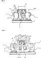
Figure 1 - Figure 1 is a top plan view schematically showing the entire structure of a working system according to an embodiment of the present invention. -
Figure 2 - Figure 2 is a side view schematically showing a positioning apparatus according to an embodiment of the present invention. -
Figure 3 - Figure 3 is a side view schematically showing a positioning apparatus according to an embodiment of the present invention with a portion omitted and with a portion shown in perspective. -
Figure 4 - Figure 4 is a block diagram for explaining the functional makeup of a controller according to an embodiment of the present invention. -
Figure 5 - Figure 5 is an explanatory view showing in simplified form a hot working apparatus disclosed inWO 2006/093006 . -
- 1
- first robot arm
- 2
- second robot arm
- 3
- third robot arm
- 4
- base
- 5
- mounting platform
- 6
- securing jig
- 7,8
- working manipulator (working mechanism)
- 9
- controller
- 11
- first structural member
- 12
- second structural member
- 13
- third structural member
- 14
- fourth structural member
- 14A
- first rotational bearing (rotational bearing)
- 15
- fifth structural member
- 15A
- second rotational bearing (rotational bearing)
- 16
- connecting member
- 16A
- third rotational bearing (rotational bearing)
- 21 - 23
- actuators
- 31
- servo controller
- 32
- rotation allowing control portion (rotation allowing function)
- 33
- taught operation memory
- 40
- hot working apparatus
- 41
- steel tube
- 41a
- high temperature portion
- 42
- support mechanism
- 43
- feed mechanism
- 44
- movable roller die
- 45
- heating mechanism (induction heating coil)
- 46
- water cooling apparatus
- 47
- high temperature portion forming mechanism
- 48
- bent member or sheared member
- 100
- working system
- Below, embodiments will be explained while referring to the drawings.
- As shown in
Figure 1 , a workingsystem 100 of the embodiment has three robot arms comprising afirst robot arm 1, asecond robot arm 2, and athird robot arm 3, abase 4, a mountingplatform 5, a securingjig 6, two workingmanipulators 7 and 8 (working mechanisms), and a controller 9. - Each of the two working
manipulators manipulators platform 5. - The
base 4 is formed with a roughly triangular (or trapezoidal) shape as viewed in plan, and it is secured to an installation surface such as a floor. Thefirst robot arm 1, thesecond robot arm 2, and thethird robot arm 3 are each installed in the vicinity of the three vertices of the roughlytriangular base 4. - The mounting
platform 5 is formed from a metal plate. As described above, the mountingplatform 5 is supported from below by connectingmembers 16, which are the end members of the first through third robot arms 1 - 3. - The workpiece W is secured to the mounting
platform 5 by a securingjig 6 which is provided on the top surface of the mountingplatform 5. The securingjig 6 can be any member which can secure the workpiece W to the mountingplatform 5 and is not limited to a particular securing jig. - As shown in
Figure 2 , thefirst robot arm 1, thesecond robot arm 2, and thethird robot arm 3 each have a first structural member (arm) 11, a second structural member (arm) 12, a third structural member (arm) 13, a fourthstructural member 14, a fifthstructural member 15, a connectingmember 16, a firstrotational bearing 14A, a secondrotational bearing 15A, and a thirdrotational bearing 16A. - As shown in
Figure 3 , thefirst robot arm 1, thesecond robot arm 2, and thethird robot arm 3 each have three actuators 21 - 23 inside them. The actuators 21 - 23 are each constituted by an integral servo motor, a reduction gear and a hollow portion at its center through which a cable can pass. Each of actuators 21 - 23 is connected to the controller 9 by a corresponding cable (not shown). - It is not always necessary to comprise the fourth
structural member 14 and the fifthstructural member 15, and the thirdstructural member 13 may be directly connected to the connectingmember 16. - In
Figure 3 , the actuators 21 - 23 are shown only for thefirst robot arm 1, and the actuators 21 - 23 for thesecond robot arm 2 and thethird robot arm 3 are not shown. However, both thesecond robot arm 2 and thethird robot arm 3 have actuators 21 - 23 inside them in the same manner as thefirst robot arm 1. - The
first robot arm 1, thesecond robot arm 2, and thethird robot arm 3 have the same structure as each other except that, as described below, thethird robot arm 3 is constituted so as to have a mirror image relationship to thefirst robot arm 1 and thesecond robot arm 2. The structure of only thefirst robot arm 1 will be explained in detail as follows. The end of each robot arm 1 - 3 closest to thebase 4 will be referred to as the base end, and the end of each robot arm 1 - 3 closest to the mountingplatform 5 will be referred to as the distal end. - The first
structural member 11 is mounted throughactuator 21 so as to extend upwards from the top surface of thebase 4. The axis in the lengthwise direction of the firststructural member 11 rotates with respect to thebase 4 when theactuator 21 is driven (it is a so-called rotational axis). The distal end of the firststructural member 11 is connected to the secondstructural member 12 throughactuator 22.Actuator 22 is a so-called gyrating axis. The secondstructural member 12 gyrates with respect to the firststructural member 11 whenactuator 22 is driven. - The distal end of the second
structural member 12 is connected to the thirdstructural member 13 throughactuator 23, which is also a gyrating axis. The thirdstructural member 13 pivots with respect to the secondstructural member 12 whenactuator 23 is driven. - The distal end of the third structural member is connected to the fourth
structural member 14 through the firstrotational bearing 14A. The firstrotational bearing 14A allows rotation in the so-called rotational axis direction. Due to rotation of the firstrotational bearing 14A, the fourthstructural member 14 rotates with respect to the thirdstructural member 13 about an axis which extends roughly in the lengthwise direction of the thirdstructural member 13. - The distal end of the fourth
structural member 14 is divided into two parts, and the fifthstructural member 15 is rotatably supported at the ends of the two parts by the secondrotational bearing 15A. The fifthstructural member 15 is connected to the connectingmember 16 through the thirdrotational bearing 16A. The rotational axis of the second rotational bearing 15A and the rotational axis of the thirdrotational bearing 16A are perpendicular to each other. The second rotational bearing 15A acts as a gyrating axis which permits rotation, and the third rotational bearing 16A acts as a rotational axis which permits rotation. The connectingmember 16 is secured by bolts or the like to the bottom surface of the mountingplatform 5. - As shown in
Figures 1 - 3 , the shape of the firststructural member 11 and the secondstructural member 12 of thethird robot arm 3 is bilaterally symmetrical with respect to the shape of the firststructural member 11 and the secondstructural member 12 of thefirst robot arm 1 and thesecond robot arm 2. If thefirst robot arm 1 and thesecond robot arm 2 are considered left handed, the third robot arm has a mirror image relationship so it is right handed. - The controller 9 is constituted by a computer having a memory, a processor, and an input apparatus (all of which are not shown). The controller 9 is connected through cables to the actuators provided in the first through third robot arms 1 - 3 and the two working
manipulators - As shown in
Figure 4 , the controller 9 is functionally constituted by aservo control portion 31, a rotation allowing control portion (rotation allowing function) 32, and a taughtoperation memory 33. - To the taught
operation memory 33, teaching data (the collected position data indicating the path of operation of the first through third robot arms 1 - 3 and the two workingmanipulators 7 and 8) is previously input by an unillustrated input apparatus. - Based on the teaching data stored in the taught
operation memory 33 and position signals and current signals input from the servo motors of the actuators, theservo controller 31 carries out feedback control including a position feedback loop, a speed feedback loop, and a current feedback loop (torque loop) and sends a position instruction to the servo motor of each actuator every calculation cycle. - The rotation allowing
control portion 32 has a rotation allowing function which selects one of the first through third robot arms 1 - 3 based on attitude information on the first through third robot arms 1 - 3 (position information on the corresponding actuators). When a current signal which is input from the servo motors for each actuator of the selected first through third robot arms 1 - 3 (the torque information, namely, the applied load) is larger than a previously set value, regardless of the value output from theservo controller 31, the instructed current value sent to the servo motor of each actuator is limited, and the actuators of the selected one of the first through third robot arms 1 - 3 is prevented from overloading by allowing rotation of the servo motors. - The working
system 100 which is constituted as described above allows that, even when theworkpiece 3 which is being positioned is heavy, it is supported by the first through third robot arms 1 - 3 that adequate positioning of the workpiece W is possible even if the actuators of each robot arm are small and have a low output. - As a result, the first through third robot arms 1 - 3 can be reduced in size at a lower cost. In addition, the first through third robot arms 1 - 3 do not directly hold the workpiece W but position the workpiece W through the mounting
platform 5 and the securingjig 6. Therefore, even when an error (or tolerance) in the position or the like of the connectingmembers 16 of the robot arms 1 - 3 develops, as far as it is a small error, an error in the position in any direction can be absorbed to a certain extent by deformation of the mountingplatform 5 itself or by allowing rotation with 3 degrees of freedom of the distal ends of the firstrotational bearing 14A, the secondrotational bearing 15A, and thirdrotational bearing 16A of the robot arms 1 - 3. Therefore, the action of stress to the workpiece W caused by positional error can be greatly reduced. - If the error in the position of the connecting
members 16 of the robot arms 1 - 3 is even relatively large, when a load of at least a previously teaching level is applied to the actuator of the one of the robot arms 1 - 3 which is selected in accordance with the positions of the robot arms 1 - 3, regardless of the position instructions, the rotation allowingcontrol portion 32 allows rotation of the servo motors. As a result, an excessive load is prevented from being applied to the mountingplatform 5 or the robot arms 1 - 3, excessive deformation of the mountingplatform 5 or the action of a stress thereby to the workpiece W can be prevented, and hence the workpiece W can be positioned with greater accuracy. In addition, an excessive load can be prevented from being applied to the robot arms 1 - 3, whereby an unexpected load on the robot arms 1 - 3 can be prevented from being applied. - Because the mounting
platform 5 and the workpiece W are supported by three robot arms 1 - 3, even when the operation of one of the robot arms is limited by the rotation allowingcontrol portion 32, the workpiece W can be adequately supported by the remaining two robot arms. - Each of the first through third robot arms 1 - 3 has three degrees of freedom. Therefore, compared to a direct drive parallel link mechanism, for example, the range of movement of the mounting
platform 5 can be maintained at a large value. - The first
structural member 11 of each robot arm 1 - 3 is installed in the vicinity of the three vertices of thetriangular base 4, androbot arms robot arm 3. Therefore, when the robot arms 1 - 3 are folded and mountingplatform 5 is lowered to the vicinity ofbase 4, the firststructural members 11 and the secondstructural members 12 are positioned along the triangular sides of thebase 4. As a result, interference between the three robot arms 1 - 3 can be avoided, and the footprint of the robot arms 1 - 3 to the outer side can be reduced. - An embodiment of the present invention has been explained above, but a positioning apparatus according to the present invention is not limited to the embodiment, and suitable variations can be employed without deviating from the essence of the present invention.
- For example, in the above-described embodiment, as explained above, the first through third robot arms and working manipulators are controlled by a single controller. However, the controller may be constituted by using separate members. In addition, a single robot arm may be controlled by a plurality of controllers. For example, a separate controller may perform only servo control.
-
Figure 5 is an explanatory view showing in simplified form ahot working apparatus 40 disclosed inWO 2006/093006 . - In
Embodiment 2, a movable roller die 44 of the hot workingapparatus 40 is supported by the positioning apparatus ofEmbodiment 1, wherein its installation position is movable. At first, the hot workingapparatus 40 will be briefly explained. - The
hot working apparatus 40 feeds asteel tube 41, which is supported by a support mechanism 42 so as to be able to move in its axial direction, from its upstream side towards its downstream side by afeed mechanism 43 such as employing a ball screw. Thesteel tube 41 is locally rapidly heated to a temperature range in which hardening is possible (at least the Ac3 point) by a heating mechanism (an induction heating coil) 45 downstream of the support mechanism 42, and cooling water is sprayed at thesteel tube 41 from awater cooling apparatus 46 disposed downstream of theheating mechanism 45 to rapidly cool thesteel tube 41, whereby a high temperature portion 41a at a temperature of at least the Ac3 point is formed between the location where thesteel tube 41 is heated by theinduction heating coil 45 and the location where cooling water is sprayed at thesteel tube 41. By two-dimensionally or three-dimensionally varying the position of a movable roller die 44 having at least one set of roll pairs 44a which can support thesteel tube 41 while feeding it, a bending moment or a shearing moment is applied to the high temperature portion 41a of thesteel tube 41. In this manner, the hot workingapparatus 40 manufactures a bent member or a shearedmember 48. - Namely, the hot working
apparatus 40 comprises the support mechanism 42, thefeed mechanism 43, the high temperatureportion forming mechanism 47 comprising theheating mechanism 45 and thecooling mechanism 46, the movable roller die 44 which moves while supporting one end of thesteel tube 41 with thehigh temperature portion 41 as a border, and the positioning apparatus ofEmbodiment 1 which supports the movable roller die 44 so as to move two-dimensionally or three-dimensionally, whereby a high temperature portion 41a which moves in the axial direction of an elongated material in the form of thesteel tube 41 is partially formed. For example, a casing (not shown) of the movable roller die 44 can be mounted on the top surface of the mountingplatform 5 of the positioning apparatus ofEmbodiment 1, and it can be installed in a prescribed fixed position by asuitable securing jig 6. - As a
feed mechanism 43 which is disposed at the other end of thesteel tube 41 with the high temperature portion 41a as a border, a conventional feed apparatus using a ball screw, for example, and an industrial robot are used. The movable roller die 44 which is supported by the device explained atEmbodiment 1 so as to move two-dimensionally or three-dimensionally can apply a bending moment or a shearing moment to the high temperature portion 41 a of thesteel tube 41 in accordance with the manner of movement of the movable roller die 44, whereby thesteel tube 41 can be bended or sheared. - Due to the hot working
apparatus 40 being constituted as discussed above, even when thesteel tube 41 is heavy, since the weight is shared among the first through third robot arms 1 - 3, it is possible to adequately position thesteel tube 41 even if the actuators of the robot arm are small and have a low output. - As a result, the first through third robot arms 1 - 3 can be downsized at a lower cost. Because the movable roller die 44 is not held by the first through third robot arms 1 - 3 but is positioned by the mounting
platform 5 and the securingjig 6, even when errors (or tolerance) develop in the installation positions of the connectingmembers 16 of the robot arms 1 - 3, as far as the error is of a small scale, positional error in any direction can be absorbed to a certain extent by deformation of the mountingplatform 5 itself or by allowing rotation with 3 degrees of freedom of the distal ends of the robot arms 1 - 3 by the firstrotational bearing 14A, the secondrotational bearing 15A, and the thirdrotational bearing 16A, and the action of stresses to the movable roller die 44 due to positional errors can be greatly reduced. - If the positional error of the connecting
members 16 of the robot arms 1 - 3 is relatively large, the rotation allowingcontrol portion 32 allows appropriate rotation of the servo motors neglecting the position instructions when a load exceeding a previously teaching load is applied to each actuator of a robot arm which is selected from robot arms 1 - 3 in accordance with the attitude of each robot arm. Therefore, an excessive load is prevented from being applied to the mountingplatform 5 and the robot arms 1 - 3, and excessive deformation of the mountingplatform 5 or the action of a stress load or the like to the movable roller die 44 due to such deformation can be suppressed, making it possible to position the movable roller die 44 more precisely. In addition, the application of an excessive load to the robot arms 1 - 3 can be prevented, so the application of unexpected loads to the robot arms 1 - 3 can be avoided. - As the mounting
platform 5 and the movable roller die 44 are supported by three robot arms 1 - 3, even when the movement of one of the robot arms is limited by the rotation allowingcontrol portion 32, the movable roller die 44 can be adequately supported by the remaining two robot arms. - Each of the first through third robot arms 1 - 3 has three degrees of freedom. Therefore, a greater range of movement of the mounting
platform 5 can be guaranteed compared to a direct-drive parallel link mechanism or the like. - The first
structural member 11 of each robot arm 1 - 3 is installed in the vicinity of the three vertices of thetriangular base 4, androbot arms robot arm 3. Therefore, when the robot arms 1 - 3 are folded and the mountingplatform 5 is lowered to the vicinity of thebase 4, the firststructural members 11 and the secondstructural members 12 are positioned along the triangular sides of thebase 4. As a result, interference among the robot arms 1 - 3 can be avoided, and the footprint over the outer sides of the robot arms 1 - 3 can be reduced. - In this manner, the movable roller die 44 of the hot working
apparatus 40 can be positioned with high accuracy and can be positioned over a wide range of operation by a simple and inexpensive positioning apparatus. Therefore, a bent member or a shearedmember 48 can be reliably and inexpensively manufactured with a high dimensional accuracy in a small installation space. - In order to prevent deformation of the
steel tube 41 after hot working and a decrease in the dimensional accuracy of a bent member or a shearedmember 48 due to the application of a bending moment to the high temperature portion 41a of thesteel tube 41 caused by an increase in the weight of the portion of thesteel tube 41 which extends from the movable roller die 44 (referred to below as the end portion) as working progresses, it is preferable to support the end portion by a suitable means (referred to below as a deformation suppressing member) to prevent a bending moment from acting on the high temperature portion 41a. Such a deformation suppressing member is not limited to a prescribed member, and it can be any member which can suppress deformation of thesteel tube 41. For example, a suitable support base or support member may be used, but it is particularly preferable to use a general purpose articulated industrial robot which is installed so as to be able to move within a prescribed space and which supports the end portion of thesteel tube 41.
Claims (8)
- A positioning apparatus which comprises:three robot arms (1,2,3) each having an actuator (21, 22, 23) for driving the respective arm,a mounting platform (5) which is supported by the ends of the three robot arms (1,2,3),a securing jig (6) for securing a workpiece (W) to the mounting platform (5), anda controller (9) for controlling the operation of the actuators (21, 22, 23),wherein one (3) of the three robot arms is constituted so as to have a mirror image relationship with respect to the other robot arms (1,2).
- A positioning apparatus according to claim 1, further comprising a base (4), wherein the three robot arms (1, 2, 3) each comprise:a first structural member (11) which is rotatably connected to the base (4) through a first actuator (21),a second structural member (12) which is gyratory connected to the first structural member (11) through a second actuator (22),a third structural member (13) which is gyratory connected to the second structural (12) member through a third actuator (23), anda connecting member (16) which is secured to the mounting platform (5) and is connected to the third structural member (13) through at least one rotatable bearing (14A, 15A, 16A).
- A positioning apparatus according to claim 1 or claim 2, wherein the actuator (21, 22, 23) has a servo motor which is driven based on a position instruction from the controller (9), and
the controller (9) has a rotation allowing function (32) which when a load exceeding a previously teaching level is applied to an actuator (21, 22, 23) of at least one of the three robot arms (1, 2, 3), regardless of the position instruction, allows rotation of the servo motor to prevent the application of an excessive load to the actuator. - A working system (100) which comprises:a positioning apparatus according to any one of claims 1-3, anda working mechanism (7, 8) for performing a working operation on a workpiece (W) which is positioned by the positioning apparatus.
- The working system according to claim 4, wherein the working operation includes at least one of welding, bolt tightening and assembly on the workpiece secured to the mounting platform (5).
- A hot working apparatus (40) which comprises
a high temperature portion forming mechanism (45) for partially forming a high temperature portion (41 a) which moves in the axial direction of an elongated material being worked (41),
a movable roller die (44) which is adapted to move while supporting one end of the material being worked (41) with the high temperature portion (41a) as a border, and a positioning apparatus according to any one of claims 1 - 3 which supports the movable roller die (44) so as to be able to move two-dimensionally or three-dimensionally. - The hot working apparatus according to claim 6, wherein the movable roller die (44) is adapted for applying a bending moment or a shearing moment to the high temperature portion (41a) of the elongated material being worked (41) in accordance with the manner of movement of the movable roller die (44), in order to bend or shear the steel tube (41).
- Method of manufacturing a bent or sheared member (48) from a steel tube (41) by the hot working apparatus according to any one of claims 6 to 7, the method comprising:supporting the steel tube (41) by a support mechanism (42) so as to be able to move in its axial direction;feeding the steel tube (41) from its upstream side towards its downstream side by a feed mechanism (43);heating the steel tube (41) locally rapidly to a temperature range in which hardening is possible by a heating mechanism (45) downstream of the support mechanism (42), andspraying cooling water at the steel tube (41) from a water cooling apparatus (46) disposed downstream of the heating mechanism (45) to rapidly cool the steel tube (41), whereby the high temperature portion (41 a) at a temperature of at least the Ac3 point is formed between the location where the steel tube (41) is heated by the heating mechanism (45) and the location where cooling water is sprayed at the steel tube (41), andvarying two-dimensionally or three-dimensionally the position of the movable roller die (44) having at least one set of roll pairs (44a) which can support the steel tube (41) while feeding it, thereby applying a bending moment or a shearing moment to the high temperature portion (41 a) of the steel tube (41), thereby obtaining the bent or sheared member (48).
Applications Claiming Priority (2)
| Application Number | Priority Date | Filing Date | Title |
|---|---|---|---|
| JP2010054077 | 2010-03-11 | ||
| PCT/JP2011/055590 WO2011111765A1 (en) | 2010-03-11 | 2011-03-10 | Positioning device, working system, and hot working apparatus |
Publications (3)
| Publication Number | Publication Date |
|---|---|
| EP2546031A1 EP2546031A1 (en) | 2013-01-16 |
| EP2546031A4 EP2546031A4 (en) | 2014-04-02 |
| EP2546031B1 true EP2546031B1 (en) | 2017-06-14 |
Family
ID=44563564
Family Applications (1)
| Application Number | Title | Priority Date | Filing Date |
|---|---|---|---|
| EP11753423.0A Not-in-force EP2546031B1 (en) | 2010-03-11 | 2011-03-10 | Positioning device, working system, and hot working apparatus |
Country Status (12)
| Country | Link |
|---|---|
| US (1) | US9409269B2 (en) |
| EP (1) | EP2546031B1 (en) |
| JP (1) | JP5499156B2 (en) |
| KR (1) | KR101478420B1 (en) |
| CN (1) | CN102834229B (en) |
| AU (1) | AU2011225217B2 (en) |
| BR (1) | BR112012022919A2 (en) |
| CA (1) | CA2792536C (en) |
| EA (1) | EA024239B1 (en) |
| MX (1) | MX2012010435A (en) |
| WO (1) | WO2011111765A1 (en) |
| ZA (1) | ZA201206765B (en) |
Families Citing this family (16)
| Publication number | Priority date | Publication date | Assignee | Title |
|---|---|---|---|---|
| US9273961B2 (en) * | 2012-02-27 | 2016-03-01 | Lit Motors Corporation | Dynamically balanced flywheel |
| CN105269557B (en) * | 2012-03-23 | 2017-06-23 | Ntn株式会社 | Link actuation device |
| CZ304673B6 (en) * | 2012-09-10 | 2014-08-27 | ÄŚVUT v Praze, Fakulta strojnĂ | A method and a device for change of rigidity of a serial or parallel basic movable mechanism, especially of industrial robots and machine tools |
| GB201303255D0 (en) * | 2013-02-25 | 2013-04-10 | Univ Bristol | Collaborating robots |
| CN108942205B (en) * | 2013-03-26 | 2020-11-27 | 株式会社尼康 | Processing apparatus and automatic processing method |
| JP6101594B2 (en) * | 2013-08-05 | 2017-03-22 | Dmg森精機株式会社 | Reinstallation method of supported objects |
| US20150251776A1 (en) * | 2014-03-05 | 2015-09-10 | Intelliport Corporation | Engine installation apparatus |
| JP6453066B2 (en) * | 2014-12-05 | 2019-01-16 | Ntn株式会社 | Control method of link actuator |
| DE102015117630B3 (en) * | 2015-10-16 | 2016-09-22 | Horst Witte Gerätebau Barskamp KG | Device and method for positioning workpieces by means of several robot arms |
| RU2667236C1 (en) * | 2017-10-11 | 2018-09-17 | Федеральное государственное бюджетное образовательное учреждение высшего образования "Сибирский государственный индустриальный университет" | Spatial mechanism with circular lever base |
| CN108068112A (en) * | 2017-11-02 | 2018-05-25 | 中车工业研究院有限公司 | A kind of device, implementation method and the processing method of same station workpieces processing |
| CN108393618A (en) * | 2018-03-29 | 2018-08-14 | 广州瑞松北斗汽车装备有限公司 | Reciprocating machine people's welding system of the main spelling system of automobile flexible |
| FR3082988B1 (en) * | 2018-06-26 | 2021-09-10 | Framatome Sa | INTERVENTION DEVICE ON A NUCLEAR FUEL ASSEMBLY |
| AT522896B1 (en) * | 2019-09-02 | 2021-12-15 | Trumpf Maschinen Austria Gmbh & Co Kg | Manipulator arrangement and method for bending a component |
| JP2021074789A (en) | 2019-11-05 | 2021-05-20 | 株式会社ジェイテクト | Assist device |
| CN112849398B (en) * | 2021-02-20 | 2022-11-15 | 复旦大学 | A bionic multifunctional rotorcraft |
Family Cites Families (23)
| Publication number | Priority date | Publication date | Assignee | Title |
|---|---|---|---|---|
| JPS62181888A (en) * | 1986-02-07 | 1987-08-10 | 三菱電機株式会社 | Industrial robot device |
| US5271290A (en) * | 1991-10-29 | 1993-12-21 | United Kingdom Atomic Energy Authority | Actuator assembly |
| US5737500A (en) * | 1992-03-11 | 1998-04-07 | California Institute Of Technology | Mobile dexterous siren degree of freedom robot arm with real-time control system |
| KR960703357A (en) * | 1993-07-08 | 1996-08-17 | 나카타 츠토무 | METHOD AND APPARATUS FOR SUPPORTING A ROLL MOLDING MACHINE STAND, AND METHOD AND APPARATUS FOR MEASURING A SUPPORTING PLATFORM POSITION |
| US5787758A (en) * | 1996-09-03 | 1998-08-04 | Sheldon/Van Someren, Inc. | Three-axis machine for rapid and rigid manipulation of components |
| JPH10329078A (en) * | 1997-06-02 | 1998-12-15 | Ricoh Co Ltd | Parallel link manipulator device |
| JP3072896B1 (en) * | 1999-04-01 | 2000-08-07 | ヒーハイスト精工株式会社 | Hybrid multi-degree-of-freedom mechanism |
| US7637710B2 (en) * | 2002-01-16 | 2009-12-29 | Abb Ab | Industrial robot |
| JP2005040919A (en) * | 2003-07-24 | 2005-02-17 | Sony Corp | Motion base |
| JP2005144627A (en) * | 2003-11-18 | 2005-06-09 | Ntn Corp | Link operating device |
| CN1878640A (en) * | 2003-12-03 | 2006-12-13 | Ntn株式会社 | Link operating device |
| JP4825019B2 (en) * | 2005-03-03 | 2011-11-30 | 住友金属工業株式会社 | Bending method of metal material, bending apparatus and bending equipment row, and bending product using them |
| EP1857195B8 (en) * | 2005-03-03 | 2014-07-30 | Nippon Steel & Sumitomo Metal Corporation | Method for bending metal material and bent product |
| US7331750B2 (en) * | 2005-03-21 | 2008-02-19 | Michael Merz | Parallel robot |
| WO2006102393A2 (en) * | 2005-03-22 | 2006-09-28 | Ross-Hime Designs, Incorporated | Robotic manipulator |
| DE102005039817A1 (en) * | 2005-08-22 | 2007-03-22 | Brötje-Automation GmbH | A robotic machine tool holder has a tool carrier linked to suction pads by jointed arms by which the tool position may be altered over the work piece |
| JP4791168B2 (en) | 2005-12-12 | 2011-10-12 | 川崎重工業株式会社 | Positioning robot |
| DE102006011823A1 (en) * | 2006-03-13 | 2007-09-20 | Abb Patent Gmbh | positioning |
| DE102007004166A1 (en) * | 2007-01-29 | 2008-08-14 | Robert Bosch Gmbh | Device for moving and positioning an object in space |
| CN101414745B (en) * | 2007-10-18 | 2011-09-21 | 茂达电子股份有限公司 | Motor protection device and method thereof |
| WO2009148603A1 (en) * | 2008-06-04 | 2009-12-10 | Ross-Hime Designs, Inc. | Robotic manipulator |
| JP5675258B2 (en) * | 2010-10-14 | 2015-02-25 | Ntn株式会社 | Link actuator |
| DE102012211190B4 (en) * | 2012-06-28 | 2019-07-18 | Deutsches Zentrum für Luft- und Raumfahrt e.V. | motion simulator |
-
2011
- 2011-03-10 CN CN201180017044.XA patent/CN102834229B/en active Active
- 2011-03-10 EA EA201290842A patent/EA024239B1/en not_active IP Right Cessation
- 2011-03-10 MX MX2012010435A patent/MX2012010435A/en not_active Application Discontinuation
- 2011-03-10 EP EP11753423.0A patent/EP2546031B1/en not_active Not-in-force
- 2011-03-10 WO PCT/JP2011/055590 patent/WO2011111765A1/en not_active Ceased
- 2011-03-10 CA CA2792536A patent/CA2792536C/en not_active Expired - Fee Related
- 2011-03-10 KR KR1020127025615A patent/KR101478420B1/en active Active
- 2011-03-10 JP JP2012504508A patent/JP5499156B2/en active Active
- 2011-03-10 AU AU2011225217A patent/AU2011225217B2/en not_active Ceased
- 2011-03-10 BR BR112012022919A patent/BR112012022919A2/en not_active Application Discontinuation
-
2012
- 2012-09-07 US US13/606,686 patent/US9409269B2/en active Active
- 2012-09-10 ZA ZA2012/06765A patent/ZA201206765B/en unknown
Also Published As
| Publication number | Publication date |
|---|---|
| WO2011111765A1 (en) | 2011-09-15 |
| CN102834229B (en) | 2015-03-18 |
| AU2011225217A1 (en) | 2012-10-25 |
| US20130239639A1 (en) | 2013-09-19 |
| KR20120135418A (en) | 2012-12-13 |
| EP2546031A4 (en) | 2014-04-02 |
| EP2546031A1 (en) | 2013-01-16 |
| JP5499156B2 (en) | 2014-05-21 |
| EA024239B1 (en) | 2016-08-31 |
| ZA201206765B (en) | 2013-09-25 |
| US9409269B2 (en) | 2016-08-09 |
| CA2792536C (en) | 2014-08-19 |
| CA2792536A1 (en) | 2011-09-15 |
| KR101478420B1 (en) | 2014-12-31 |
| MX2012010435A (en) | 2013-01-29 |
| BR112012022919A2 (en) | 2018-05-22 |
| AU2011225217B2 (en) | 2014-11-20 |
| CN102834229A (en) | 2012-12-19 |
| JPWO2011111765A1 (en) | 2013-06-27 |
| EA201290842A1 (en) | 2013-02-28 |
Similar Documents
| Publication | Publication Date | Title |
|---|---|---|
| US9409269B2 (en) | Positioning apparatus, working system, and hot working apparatus | |
| EP2213425B1 (en) | Vertical multi-joint robot | |
| EP2255933B1 (en) | Robot system | |
| JP3640087B2 (en) | Machine Tools | |
| EP2147756B1 (en) | Transfer robot | |
| CN114851233B (en) | End execution device and execution method for industrial robot machining | |
| KR20130020524A (en) | Robot and robot system | |
| CN106002987A (en) | robot | |
| JP5770430B2 (en) | Bending machine | |
| JP5748545B2 (en) | Metal processing equipment | |
| WO2014123054A1 (en) | Robot control device and robot control method | |
| Brogårdh et al. | Application-oriented development of parallel kinematic manipulators with large workspace | |
| KR20110085865A (en) | Robot system and positioner with positioner | |
| JP5939036B2 (en) | Bending machine | |
| Bai et al. | Design of mechanical presses driven by multi-servomotor | |
| JP4825614B2 (en) | Trajectory control device for articulated link mechanism | |
| JP5580682B2 (en) | Hemming equipment | |
| JP6406063B2 (en) | Bending member manufacturing method and manufacturing apparatus | |
| KR102920407B1 (en) | Real-time motion synchronization control method based on multi-axis expansion of collaborative robot | |
| JP7282648B2 (en) | robot controller | |
| JP2019171424A (en) | Spot welding device | |
| JP2026077366A (en) | Friction stir welding system | |
| CN120190642A (en) | A method for quickly detecting the machining allowance of the waist shell of industrial robot parts | |
| TH125237A (en) | Positioning device Hot forging system and equipment | |
| CN115475968A (en) | Synchronous accompanying type low-stress manufacturing equipment and method |
Legal Events
| Date | Code | Title | Description |
|---|---|---|---|
| PUAI | Public reference made under article 153(3) epc to a published international application that has entered the european phase |
Free format text: ORIGINAL CODE: 0009012 |
|
| 17P | Request for examination filed |
Effective date: 20120927 |
|
| AK | Designated contracting states |
Kind code of ref document: A1 Designated state(s): AL AT BE BG CH CY CZ DE DK EE ES FI FR GB GR HR HU IE IS IT LI LT LU LV MC MK MT NL NO PL PT RO RS SE SI SK SM TR |
|
| RAP1 | Party data changed (applicant data changed or rights of an application transferred) |
Owner name: NIPPON STEEL & SUMITOMO METAL CORPORATION Owner name: KABUSHIKI KAISHA YASKAWA DENKI Owner name: SUMITOMO PIPE & TUBE CO., LTD. |
|
| DAX | Request for extension of the european patent (deleted) | ||
| A4 | Supplementary search report drawn up and despatched |
Effective date: 20140305 |
|
| RIC1 | Information provided on ipc code assigned before grant |
Ipc: B25J 11/00 20060101AFI20140227BHEP |
|
| GRAP | Despatch of communication of intention to grant a patent |
Free format text: ORIGINAL CODE: EPIDOSNIGR1 |
|
| INTG | Intention to grant announced |
Effective date: 20160719 |
|
| GRAS | Grant fee paid |
Free format text: ORIGINAL CODE: EPIDOSNIGR3 |
|
| RAP1 | Party data changed (applicant data changed or rights of an application transferred) |
Owner name: NIPPON STEEL & SUMITOMO METAL CORPORATION Owner name: KABUSHIKI KAISHA YASKAWA DENKI Owner name: NIPPON STEEL & SUMIKIN PIPE CO., LTD. |
|
| GRAA | (expected) grant |
Free format text: ORIGINAL CODE: 0009210 |
|
| RAP1 | Party data changed (applicant data changed or rights of an application transferred) |
Owner name: NIPPON STEEL & SUMIKIN PIPE CO., LTD. Owner name: KABUSHIKI KAISHA YASKAWA DENKI Owner name: NIPPON STEEL & SUMITOMO METAL CORPORATION |
|
| AK | Designated contracting states |
Kind code of ref document: B1 Designated state(s): AL AT BE BG CH CY CZ DE DK EE ES FI FR GB GR HR HU IE IS IT LI LT LU LV MC MK MT NL NO PL PT RO RS SE SI SK SM TR |
|
| REG | Reference to a national code |
Ref country code: GB Ref legal event code: FG4D |
|
| REG | Reference to a national code |
Ref country code: CH Ref legal event code: EP Ref country code: AT Ref legal event code: REF Ref document number: 900518 Country of ref document: AT Kind code of ref document: T Effective date: 20170615 |
|
| REG | Reference to a national code |
Ref country code: IE Ref legal event code: FG4D |
|
| REG | Reference to a national code |
Ref country code: DE Ref legal event code: R096 Ref document number: 602011038721 Country of ref document: DE |
|
| REG | Reference to a national code |
Ref country code: NL Ref legal event code: MP Effective date: 20170614 |
|
| REG | Reference to a national code |
Ref country code: LT Ref legal event code: MG4D |
|
| PG25 | Lapsed in a contracting state [announced via postgrant information from national office to epo] |
Ref country code: HR Free format text: LAPSE BECAUSE OF FAILURE TO SUBMIT A TRANSLATION OF THE DESCRIPTION OR TO PAY THE FEE WITHIN THE PRESCRIBED TIME-LIMIT Effective date: 20170614 Ref country code: LT Free format text: LAPSE BECAUSE OF FAILURE TO SUBMIT A TRANSLATION OF THE DESCRIPTION OR TO PAY THE FEE WITHIN THE PRESCRIBED TIME-LIMIT Effective date: 20170614 Ref country code: FI Free format text: LAPSE BECAUSE OF FAILURE TO SUBMIT A TRANSLATION OF THE DESCRIPTION OR TO PAY THE FEE WITHIN THE PRESCRIBED TIME-LIMIT Effective date: 20170614 Ref country code: NO Free format text: LAPSE BECAUSE OF FAILURE TO SUBMIT A TRANSLATION OF THE DESCRIPTION OR TO PAY THE FEE WITHIN THE PRESCRIBED TIME-LIMIT Effective date: 20170914 Ref country code: GR Free format text: LAPSE BECAUSE OF FAILURE TO SUBMIT A TRANSLATION OF THE DESCRIPTION OR TO PAY THE FEE WITHIN THE PRESCRIBED TIME-LIMIT Effective date: 20170915 Ref country code: ES Free format text: LAPSE BECAUSE OF FAILURE TO SUBMIT A TRANSLATION OF THE DESCRIPTION OR TO PAY THE FEE WITHIN THE PRESCRIBED TIME-LIMIT Effective date: 20170614 |
|
| REG | Reference to a national code |
Ref country code: AT Ref legal event code: MK05 Ref document number: 900518 Country of ref document: AT Kind code of ref document: T Effective date: 20170614 |
|
| PG25 | Lapsed in a contracting state [announced via postgrant information from national office to epo] |
Ref country code: BG Free format text: LAPSE BECAUSE OF FAILURE TO SUBMIT A TRANSLATION OF THE DESCRIPTION OR TO PAY THE FEE WITHIN THE PRESCRIBED TIME-LIMIT Effective date: 20170914 Ref country code: RS Free format text: LAPSE BECAUSE OF FAILURE TO SUBMIT A TRANSLATION OF THE DESCRIPTION OR TO PAY THE FEE WITHIN THE PRESCRIBED TIME-LIMIT Effective date: 20170614 Ref country code: SE Free format text: LAPSE BECAUSE OF FAILURE TO SUBMIT A TRANSLATION OF THE DESCRIPTION OR TO PAY THE FEE WITHIN THE PRESCRIBED TIME-LIMIT Effective date: 20170614 Ref country code: NL Free format text: LAPSE BECAUSE OF FAILURE TO SUBMIT A TRANSLATION OF THE DESCRIPTION OR TO PAY THE FEE WITHIN THE PRESCRIBED TIME-LIMIT Effective date: 20170614 Ref country code: LV Free format text: LAPSE BECAUSE OF FAILURE TO SUBMIT A TRANSLATION OF THE DESCRIPTION OR TO PAY THE FEE WITHIN THE PRESCRIBED TIME-LIMIT Effective date: 20170614 |
|
| PG25 | Lapsed in a contracting state [announced via postgrant information from national office to epo] |
Ref country code: SK Free format text: LAPSE BECAUSE OF FAILURE TO SUBMIT A TRANSLATION OF THE DESCRIPTION OR TO PAY THE FEE WITHIN THE PRESCRIBED TIME-LIMIT Effective date: 20170614 Ref country code: EE Free format text: LAPSE BECAUSE OF FAILURE TO SUBMIT A TRANSLATION OF THE DESCRIPTION OR TO PAY THE FEE WITHIN THE PRESCRIBED TIME-LIMIT Effective date: 20170614 Ref country code: CZ Free format text: LAPSE BECAUSE OF FAILURE TO SUBMIT A TRANSLATION OF THE DESCRIPTION OR TO PAY THE FEE WITHIN THE PRESCRIBED TIME-LIMIT Effective date: 20170614 Ref country code: AT Free format text: LAPSE BECAUSE OF FAILURE TO SUBMIT A TRANSLATION OF THE DESCRIPTION OR TO PAY THE FEE WITHIN THE PRESCRIBED TIME-LIMIT Effective date: 20170614 Ref country code: RO Free format text: LAPSE BECAUSE OF FAILURE TO SUBMIT A TRANSLATION OF THE DESCRIPTION OR TO PAY THE FEE WITHIN THE PRESCRIBED TIME-LIMIT Effective date: 20170614 |
|
| REG | Reference to a national code |
Ref country code: FR Ref legal event code: PLFP Year of fee payment: 8 |
|
| PG25 | Lapsed in a contracting state [announced via postgrant information from national office to epo] |
Ref country code: PL Free format text: LAPSE BECAUSE OF FAILURE TO SUBMIT A TRANSLATION OF THE DESCRIPTION OR TO PAY THE FEE WITHIN THE PRESCRIBED TIME-LIMIT Effective date: 20170614 Ref country code: SM Free format text: LAPSE BECAUSE OF FAILURE TO SUBMIT A TRANSLATION OF THE DESCRIPTION OR TO PAY THE FEE WITHIN THE PRESCRIBED TIME-LIMIT Effective date: 20170614 Ref country code: IS Free format text: LAPSE BECAUSE OF FAILURE TO SUBMIT A TRANSLATION OF THE DESCRIPTION OR TO PAY THE FEE WITHIN THE PRESCRIBED TIME-LIMIT Effective date: 20171014 |
|
| REG | Reference to a national code |
Ref country code: DE Ref legal event code: R097 Ref document number: 602011038721 Country of ref document: DE |
|
| PLBE | No opposition filed within time limit |
Free format text: ORIGINAL CODE: 0009261 |
|
| STAA | Information on the status of an ep patent application or granted ep patent |
Free format text: STATUS: NO OPPOSITION FILED WITHIN TIME LIMIT |
|
| PG25 | Lapsed in a contracting state [announced via postgrant information from national office to epo] |
Ref country code: DK Free format text: LAPSE BECAUSE OF FAILURE TO SUBMIT A TRANSLATION OF THE DESCRIPTION OR TO PAY THE FEE WITHIN THE PRESCRIBED TIME-LIMIT Effective date: 20170614 |
|
| 26N | No opposition filed |
Effective date: 20180315 |
|
| PG25 | Lapsed in a contracting state [announced via postgrant information from national office to epo] |
Ref country code: SI Free format text: LAPSE BECAUSE OF FAILURE TO SUBMIT A TRANSLATION OF THE DESCRIPTION OR TO PAY THE FEE WITHIN THE PRESCRIBED TIME-LIMIT Effective date: 20170614 |
|
| REG | Reference to a national code |
Ref country code: CH Ref legal event code: PL |
|
| PG25 | Lapsed in a contracting state [announced via postgrant information from national office to epo] |
Ref country code: MC Free format text: LAPSE BECAUSE OF FAILURE TO SUBMIT A TRANSLATION OF THE DESCRIPTION OR TO PAY THE FEE WITHIN THE PRESCRIBED TIME-LIMIT Effective date: 20170614 |
|
| REG | Reference to a national code |
Ref country code: BE Ref legal event code: MM Effective date: 20180331 |
|
| REG | Reference to a national code |
Ref country code: IE Ref legal event code: MM4A |
|
| PG25 | Lapsed in a contracting state [announced via postgrant information from national office to epo] |
Ref country code: LU Free format text: LAPSE BECAUSE OF NON-PAYMENT OF DUE FEES Effective date: 20180310 |
|
| PG25 | Lapsed in a contracting state [announced via postgrant information from national office to epo] |
Ref country code: IE Free format text: LAPSE BECAUSE OF NON-PAYMENT OF DUE FEES Effective date: 20180310 |
|
| PG25 | Lapsed in a contracting state [announced via postgrant information from national office to epo] |
Ref country code: CH Free format text: LAPSE BECAUSE OF NON-PAYMENT OF DUE FEES Effective date: 20180331 Ref country code: BE Free format text: LAPSE BECAUSE OF NON-PAYMENT OF DUE FEES Effective date: 20180331 Ref country code: LI Free format text: LAPSE BECAUSE OF NON-PAYMENT OF DUE FEES Effective date: 20180331 |
|
| REG | Reference to a national code |
Ref country code: DE Ref legal event code: R082 Ref document number: 602011038721 Country of ref document: DE Representative=s name: ZIMMERMANN & PARTNER PATENTANWAELTE MBB, DE Ref country code: DE Ref legal event code: R081 Ref document number: 602011038721 Country of ref document: DE Owner name: NIPPON STEEL CORPORATION, JP Free format text: FORMER OWNERS: KABUSHIKI KAISHA YASKAWA DENKI, KITAKYUSHU-SHI, FUKUOKA, JP; NIPPON STEEL & SUMIKIN PIPE CO. LTD., TOKYO, JP; NIPPON STEEL & SUMITOMO METAL CORPORATION, TOKYO, JP Ref country code: DE Ref legal event code: R081 Ref document number: 602011038721 Country of ref document: DE Owner name: NIPPON STEEL & SUMIKIN PIPE CO. LTD., JP Free format text: FORMER OWNERS: KABUSHIKI KAISHA YASKAWA DENKI, KITAKYUSHU-SHI, FUKUOKA, JP; NIPPON STEEL & SUMIKIN PIPE CO. LTD., TOKYO, JP; NIPPON STEEL & SUMITOMO METAL CORPORATION, TOKYO, JP Ref country code: DE Ref legal event code: R081 Ref document number: 602011038721 Country of ref document: DE Owner name: KABUSHIKI KAISHA YASKAWA DENKI, KITAKYUSHU-SHI, JP Free format text: FORMER OWNERS: KABUSHIKI KAISHA YASKAWA DENKI, KITAKYUSHU-SHI, FUKUOKA, JP; NIPPON STEEL & SUMIKIN PIPE CO. LTD., TOKYO, JP; NIPPON STEEL & SUMITOMO METAL CORPORATION, TOKYO, JP |
|
| PG25 | Lapsed in a contracting state [announced via postgrant information from national office to epo] |
Ref country code: MT Free format text: LAPSE BECAUSE OF NON-PAYMENT OF DUE FEES Effective date: 20180310 |
|
| PGFP | Annual fee paid to national office [announced via postgrant information from national office to epo] |
Ref country code: DE Payment date: 20200225 Year of fee payment: 10 Ref country code: GB Payment date: 20200226 Year of fee payment: 10 Ref country code: IT Payment date: 20200221 Year of fee payment: 10 |
|
| PG25 | Lapsed in a contracting state [announced via postgrant information from national office to epo] |
Ref country code: HU Free format text: LAPSE BECAUSE OF FAILURE TO SUBMIT A TRANSLATION OF THE DESCRIPTION OR TO PAY THE FEE WITHIN THE PRESCRIBED TIME-LIMIT; INVALID AB INITIO Effective date: 20110310 Ref country code: PT Free format text: LAPSE BECAUSE OF FAILURE TO SUBMIT A TRANSLATION OF THE DESCRIPTION OR TO PAY THE FEE WITHIN THE PRESCRIBED TIME-LIMIT Effective date: 20170614 |
|
| PG25 | Lapsed in a contracting state [announced via postgrant information from national office to epo] |
Ref country code: MK Free format text: LAPSE BECAUSE OF NON-PAYMENT OF DUE FEES Effective date: 20170614 Ref country code: CY Free format text: LAPSE BECAUSE OF FAILURE TO SUBMIT A TRANSLATION OF THE DESCRIPTION OR TO PAY THE FEE WITHIN THE PRESCRIBED TIME-LIMIT Effective date: 20170614 |
|
| PGFP | Annual fee paid to national office [announced via postgrant information from national office to epo] |
Ref country code: TR Payment date: 20200309 Year of fee payment: 10 Ref country code: FR Payment date: 20200214 Year of fee payment: 10 |
|
| PG25 | Lapsed in a contracting state [announced via postgrant information from national office to epo] |
Ref country code: AL Free format text: LAPSE BECAUSE OF FAILURE TO SUBMIT A TRANSLATION OF THE DESCRIPTION OR TO PAY THE FEE WITHIN THE PRESCRIBED TIME-LIMIT Effective date: 20170614 |
|
| REG | Reference to a national code |
Ref country code: DE Ref legal event code: R119 Ref document number: 602011038721 Country of ref document: DE |
|
| GBPC | Gb: european patent ceased through non-payment of renewal fee |
Effective date: 20210310 |
|
| PG25 | Lapsed in a contracting state [announced via postgrant information from national office to epo] |
Ref country code: FR Free format text: LAPSE BECAUSE OF NON-PAYMENT OF DUE FEES Effective date: 20210331 Ref country code: GB Free format text: LAPSE BECAUSE OF NON-PAYMENT OF DUE FEES Effective date: 20210310 Ref country code: DE Free format text: LAPSE BECAUSE OF NON-PAYMENT OF DUE FEES Effective date: 20211001 |
|
| PG25 | Lapsed in a contracting state [announced via postgrant information from national office to epo] |
Ref country code: IT Free format text: LAPSE BECAUSE OF NON-PAYMENT OF DUE FEES Effective date: 20210310 |
|
| PG25 | Lapsed in a contracting state [announced via postgrant information from national office to epo] |
Ref country code: TR Free format text: LAPSE BECAUSE OF NON-PAYMENT OF DUE FEES Effective date: 20210310 |