EP2546007A1 - Microcircuit skin core cut back to reduce microcircuit trailing edge stresses of an airfoil - Google Patents
Microcircuit skin core cut back to reduce microcircuit trailing edge stresses of an airfoil Download PDFInfo
- Publication number
- EP2546007A1 EP2546007A1 EP12166735A EP12166735A EP2546007A1 EP 2546007 A1 EP2546007 A1 EP 2546007A1 EP 12166735 A EP12166735 A EP 12166735A EP 12166735 A EP12166735 A EP 12166735A EP 2546007 A1 EP2546007 A1 EP 2546007A1
- Authority
- EP
- European Patent Office
- Prior art keywords
- trailing edge
- core
- microcircuit
- cut
- casting system
- Prior art date
- Legal status (The legal status is an assumption and is not a legal conclusion. Google has not performed a legal analysis and makes no representation as to the accuracy of the status listed.)
- Granted
Links
Images




Classifications
-
- B—PERFORMING OPERATIONS; TRANSPORTING
- B22—CASTING; POWDER METALLURGY
- B22C—FOUNDRY MOULDING
- B22C9/00—Moulds or cores; Moulding processes
- B22C9/10—Cores; Manufacture or installation of cores
- B22C9/103—Multipart cores
-
- F—MECHANICAL ENGINEERING; LIGHTING; HEATING; WEAPONS; BLASTING
- F01—MACHINES OR ENGINES IN GENERAL; ENGINE PLANTS IN GENERAL; STEAM ENGINES
- F01D—NON-POSITIVE DISPLACEMENT MACHINES OR ENGINES, e.g. STEAM TURBINES
- F01D5/00—Blades; Blade-carrying members; Heating, heat-insulating, cooling or antivibration means on the blades or the members
- F01D5/12—Blades
- F01D5/14—Form or construction
- F01D5/18—Hollow blades, i.e. blades with cooling or heating channels or cavities; Heating, heat-insulating or cooling means on blades
- F01D5/187—Convection cooling
-
- F—MECHANICAL ENGINEERING; LIGHTING; HEATING; WEAPONS; BLASTING
- F05—INDEXING SCHEMES RELATING TO ENGINES OR PUMPS IN VARIOUS SUBCLASSES OF CLASSES F01-F04
- F05D—INDEXING SCHEME FOR ASPECTS RELATING TO NON-POSITIVE-DISPLACEMENT MACHINES OR ENGINES, GAS-TURBINES OR JET-PROPULSION PLANTS
- F05D2230/00—Manufacture
- F05D2230/20—Manufacture essentially without removing material
- F05D2230/21—Manufacture essentially without removing material by casting
- F05D2230/211—Manufacture essentially without removing material by casting by precision casting, e.g. microfusing or investment casting
-
- F—MECHANICAL ENGINEERING; LIGHTING; HEATING; WEAPONS; BLASTING
- F05—INDEXING SCHEMES RELATING TO ENGINES OR PUMPS IN VARIOUS SUBCLASSES OF CLASSES F01-F04
- F05D—INDEXING SCHEME FOR ASPECTS RELATING TO NON-POSITIVE-DISPLACEMENT MACHINES OR ENGINES, GAS-TURBINES OR JET-PROPULSION PLANTS
- F05D2260/00—Function
- F05D2260/94—Functionality given by mechanical stress related aspects such as low cycle fatigue [LCF] of high cycle fatigue [HCF]
- F05D2260/941—Functionality given by mechanical stress related aspects such as low cycle fatigue [LCF] of high cycle fatigue [HCF] particularly aimed at mechanical or thermal stress reduction
Definitions
- the present disclosure relates to a core system for use in casting an airfoil portion of a turbine engine component.
- the present disclosure shows how to locally remove the microcircuit skin core and/or microcircuit trailing edge pedestals to reduce thermal gradients across the region of the part.
- the microcircuit skin core 18 is attached to the main body core 16 so that the trailing edge 23 of the core 18 overlaps the inlet of the trailing edge refractory metal core 25 of the main body core 16.
- the overlap region 30 can cover features on the trailing edge core 20 such as the holes 31 used to form pedestals in the core 22.
- the trailing edge core 20 is also attached to the main body core 16.
- the microcircuit skin cores 18 and the trailing edge core 20 form a double wall construction shown in the circled area 24 in FIG. 2 . As a result, there is a region of the trailing edge core 26 which is shielded from the pressure side gas path.
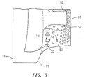
- Fig. 3 shows an arrangement of cores to be used in a casting system for forming an airfoil portion of a turbine engine component.
- Fig. 4 it has been found that removal of the portion 30 of the microcircuit skin core 18 creates a cut-back portion directly adjacent to the inlet 27 of the trailing edge core 20.
- the cut-back portion 30 is sized so that the cooling microcircuit 10 formed by the core 18 allows heat-up of the trailing edge core 22 from external skin surface 28.
- the trailing edge core 22 By allowing the trailing edge core 22 to heat up, the high thermal gradients across the trailing edge shielded region 26 can be reduced. Reductions in thermal gradients across the trailing edge 26 reduce correspondingly thermally driven stresses and strains, by up to 42%.
- the cutback microcircuit skin core 18 exposes the trailing edge core 22 to heat-up from the gas path.
- a trailing edge shielded region 26 is not present, which exposes trailing edge core 22 to the pressure side gas path.
- the cut back microcircuit skin core 18 may be cut-back to expose the holes that form the pedestals within the trailing edge core 22.
- the skin core 18 is provided with a trailing edge 40 which does not extend beyond the trailing edge 25 of the main body core 16.
- Fig. 5 shows another embodiment wherein the cut-back microcircuit skin core 18, in addition to having a trailing edge 40 which does not extend beyond the trailing edge 25 of the main body core 16, has no pedestals in an inlet region 44 of the trailing edge core 20.
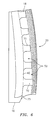
- Fig. 6 shows an embodiment where the cut-back microcircuit skin core 18 has a plurality of cut-back portions 50 which extend along the span of the skin core 18.
- the trailing edge 40 of the microcircuit skin core 18 does not extend beyond the trailing edge 25 of the main body core 16.
- An advantage to this configuration is that it exposes more of the shielded region 26.
- the core 18 may extend from a root region of the component to a tip of the component.
- the skin core 18 has a non-cut back region 70 which forms the exit for the cooling microcircuit 10.
- This non-cut back portion 70 extends beyond the trailing edge 25 of the main body core 16 and overlaps the inlet portion 44 of the trailing edge core 20.
- a cooling microcircuit 10 which is connected to an internal cavity 15 through which cooling air flows and which has an exit end 74 which terminates at the external skin surface 28.
- the cooling microcircuit 10 has a length so that it only overlaps an inlet region 27 of the trailing edge core 22 and terminates in a chordwise manner at said inlet region.
- the trailing edge core 22 is exposed to heat-up from the gas path which flows along the surface 28 of the wall in which the cooling microcircuit 10 is embedded. The effect of this arrangement is that thermal stresses are decreased in the trailing edge region.
- a test of a microcircuit without the cutback and a microcircuit with a cut-back as described hereinabove was conducted to determine the percent reduction in stress caused by the microcircuit design of the present disclosure. As shown in FIG. 10, a 42% reduction in stress was obtained.
- microcircuit skin core cut back to reduce microcircuit trailing edge stresses. While the microcircuit skin core has been described in the context of specific embodiments thereof, other unforeseen alternatives, modifications, and variations may become apparent to those skilled in the art having read the foregoing description. Accordingly, it is intended to embrace those alternatives, modifications, and variations as fall within the broad scope of the appended claims.
Landscapes
- Engineering & Computer Science (AREA)
- Mechanical Engineering (AREA)
- General Engineering & Computer Science (AREA)
- Turbine Rotor Nozzle Sealing (AREA)
- Molds, Cores, And Manufacturing Methods Thereof (AREA)
Abstract
Description
- The present disclosure relates to a core system for use in casting an airfoil portion of a turbine engine component.
- High heat load applications for turbine engine components require intermediate wall cores (microcircuits) which are embedded between a main body core and an external surface of a turbine airfoil to provide cooling and shielding from coolant heat pick up. In providing such systems in the past, unwanted thermal stresses have been created.
- In accordance with the instant disclosure, there is provided a casting system for forming an airfoil portion of a turbine engine component. The casting system broadly comprises a main body core for forming at least one internal cavity in said airfoil portion, a microcircuit skin core for forming a cooling microcircuit embedded in a wall of said airfoil portion, a trailing edge core for forming a passage in a trailing edge of said airfoil portion, and said microcircuit skin core having at least one cut-back portion which is sized so as to provide said cooling microcircuit embedded in said wall with a length which allows heat-up of the trailing edge core from a gas path.
- It has been found by the inventors that full body microcircuits are needed to cool portions of highly heat loaded turbine components. In additional embodiments, the present disclosure shows how to locally remove the microcircuit skin core and/or microcircuit trailing edge pedestals to reduce thermal gradients across the region of the part.
- Further in accordance with the present disclosure, there is provided a turbine engine component having an airfoil portion. The airfoil portion has an internal cavity through which cooling air flows, a cooling microcircuit embedded in a wall, said cooling microcircuit receiving cooling air from said internal cavity, a trailing edge core having an inlet region, and said cooling microcircuit embedded in said wall having an exit end which terminates at said inlet region of said trailing edge core so as to expose said trailing edge cooling microcircuit to heat-up from a gas path following adjacent a surface of said wall.
- Other details of the microcircuit skin core cut back to reduce microcircuit trailing edge stresses are set forth in the following detailed description and the accompanying drawings wherein like reference numerals depict like elements.
-
-
Fig. 1 is a schematic representation of a core arrangement for forming cooling microcircuits in an airfoil portion of a turbine engine component; -
Fig. 2 illustrates a cross sectional view of an airfoil portion formed using the core arrangements ofFig. 1 ; -
Fig. 3 is a schematic representation of another core arrangement for forming cooling microcircuits where the microcircuit skin core has a cut back region; -
Figs. 4 illustrates a cross sectional view of an airfoil portion formed using the casting system ofFig. 3 ; -
Fig. 5 illustrates an alternative microcircuit skin core; -
Fig. 6 illustrates a microcircuit skin core having a plurality of cut back portions; -
Fig. 7 is a graph showing the reduction in stress which occurs by using the microcircuit skin cores described herein; and -
Fig. 8 is a sectional view of an airfoil. -
FIGS. 1 and 2 illustrate anarrangement 8 of cores which are used to formcooling microcircuits airfoil portion 12 of aturbine engine component 14 such as a turbine blade. Thecore arrangement 8 includes at least onemain body core 16, which may be formed from a ceramic material and which forms one or more central orinternal passageways 15 within theairfoil portion 12, amicrocircuit skin core 18, which may be formed from a refractory metal material and which forms thecooling microcircuit 10 embedded within awall 19 of theairfoil portion 12, and atrailing edge core 20 which forms thetrailing edge core 22, which trailingedge core 20 may be formed from a refractory metal or a ceramic material. Typically, themicrocircuit skin core 18 is attached to themain body core 16 so that thetrailing edge 23 of thecore 18 overlaps the inlet of the trailing edgerefractory metal core 25 of themain body core 16. As shown inFig. 1 , theoverlap region 30 can cover features on thetrailing edge core 20 such as theholes 31 used to form pedestals in thecore 22. Thetrailing edge core 20 is also attached to themain body core 16. Themicrocircuit skin cores 18 and thetrailing edge core 20 form a double wall construction shown in thecircled area 24 inFIG. 2 . As a result, there is a region of thetrailing edge core 26 which is shielded from the pressure side gas path. -
Microcircuit skin cores 18, such as that shown inFig. 1 , create the shieldedregion 26 of thetrailing edge core 22. This is because in such designs, themicrocircuit skin core 18 creates the double wall airfoil between theexternal skin surface 28 and thetrailing edge core 22. Certain applications of such amicrocircuit skin core 18 and atrailing edge core 22 can reveal high thermal gradients across the airfoil trailing edge shieldedregion 26 as a result of the double-wall airfoil construction in this region. -
Fig. 3 shows an arrangement of cores to be used in a casting system for forming an airfoil portion of a turbine engine component. As shown inFig. 4 , it has been found that removal of theportion 30 of themicrocircuit skin core 18 creates a cut-back portion directly adjacent to theinlet 27 of thetrailing edge core 20. The cut-back portion 30 is sized so that thecooling microcircuit 10 formed by thecore 18 allows heat-up of thetrailing edge core 22 fromexternal skin surface 28. By allowing thetrailing edge core 22 to heat up, the high thermal gradients across the trailing edge shieldedregion 26 can be reduced. Reductions in thermal gradients across thetrailing edge 26 reduce correspondingly thermally driven stresses and strains, by up to 42%. - As shown in
Figs. 3 and4 , the cutbackmicrocircuit skin core 18 exposes thetrailing edge core 22 to heat-up from the gas path. As can be seen by thecircled area 24 inFig 2 , a trailing edge shieldedregion 26 is not present, which exposes trailingedge core 22 to the pressure side gas path. - The cut-back portion(s) 30 may be located anywhere along the span of the airfoil. When cutting back the
microcircuit skin core 18, the cut-back portion 30 may have agradual blend area 52, such as in the form of a curved or an arcuate section, which leads to theportion 70 of the skin core which forms the fluid exit of themicrocircuit 10 formed by theskin core 18. Thegradual blend area 52 is desirable to insure a smooth flow of fluid in thefinal microcircuit 10. As can be seen fromFig. 3 , theportion 70 may overlap the portion of thetrailing edge core 20 forming the inlet region of thetrailing edge core 22 in a chordwise direction. At least one cut-back portion 50 of theskin core 18 may be found in the region where the platform of the turbine engine component would be formed. - As shown in
Fig. 3 , the cut backmicrocircuit skin core 18 may be cut-back to expose the holes that form the pedestals within thetrailing edge core 22. Theskin core 18 is provided with atrailing edge 40 which does not extend beyond thetrailing edge 25 of themain body core 16. -
Fig. 5 shows another embodiment wherein the cut-backmicrocircuit skin core 18, in addition to having atrailing edge 40 which does not extend beyond thetrailing edge 25 of themain body core 16, has no pedestals in aninlet region 44 of thetrailing edge core 20. -
Fig. 6 shows an embodiment where the cut-backmicrocircuit skin core 18 has a plurality of cut-back portions 50 which extend along the span of theskin core 18. As in other configurations, thetrailing edge 40 of themicrocircuit skin core 18 does not extend beyond thetrailing edge 25 of themain body core 16. An advantage to this configuration is that it exposes more of the shieldedregion 26. As can be seen fromFig. 6 thecore 18 may extend from a root region of the component to a tip of the component. - As shown in each of
Figures 3 ,5 and6 , theskin core 18 has anon-cut back region 70 which forms the exit for thecooling microcircuit 10. Thisnon-cut back portion 70 extends beyond thetrailing edge 25 of themain body core 16 and overlaps theinlet portion 44 of thetrailing edge core 20. - As can be seen from
Fig. 4 , using the casting system of the present invention, one is able to form acooling microcircuit 10 which is connected to aninternal cavity 15 through which cooling air flows and which has anexit end 74 which terminates at theexternal skin surface 28. - Referring now to
Fig. 8 , thecooling microcircuit 10 has a length so that it only overlaps aninlet region 27 of thetrailing edge core 22 and terminates in a chordwise manner at said inlet region. As a result, thetrailing edge core 22 is exposed to heat-up from the gas path which flows along thesurface 28 of the wall in which thecooling microcircuit 10 is embedded. The effect of this arrangement is that thermal stresses are decreased in the trailing edge region. - A test of a microcircuit without the cutback and a microcircuit with a cut-back as described hereinabove was conducted to determine the percent reduction in stress caused by the microcircuit design of the present disclosure. As shown in FIG. 10, a 42% reduction in stress was obtained.
- As can be seen from the foregoing discussion, the microcircuit core system with the cut-back
microcircuit skin core 18 described hereinabove reduces the thermal gradients between themicrocircuit skin core 18 and the microcircuittrailing edge 22. Thermal gradients are reduced, thereby the thermal stresses are also reduced. As stresses are reduced, the fatigue capability is increased. - There has been described herein a microcircuit skin core cut back to reduce microcircuit trailing edge stresses. While the microcircuit skin core has been described in the context of specific embodiments thereof, other unforeseen alternatives, modifications, and variations may become apparent to those skilled in the art having read the foregoing description. Accordingly, it is intended to embrace those alternatives, modifications, and variations as fall within the broad scope of the appended claims.
Claims (15)
- A casting system (8) for forming an airfoil portion (12) of a turbine engine component (14), said system comprising:a main body core (16) for forming at least one internal cavity (15) in said airfoil portion (12);a microcircuit skin core (18) for forming a cooling microcircuit (10) embedded in a wall (19) of said airfoil portion (12); anda trailing edge core (20) for forming a cooling passage (22) in a trailing edge of said airfoil portion (12), said microcircuit skin core (18) having at least one cut-back portion (50).
- The casting system (8) according to claim 1, wherein said at least one cut-back portion (50) is sized so as to provide said cooling microcircuit (10) embedded in said wall (19) with a length which allows heat-up of the trailing edge core (22) from a gas path.
- The casting system (8) according to claim 1 or 2, wherein said trailing edge core (20) has a portion that forms an inlet region (44) for said trailing edge core (22) which includes a plurality of holes (31) for forming pedestals within said trailing edge core and said at least one cut-back portion (50) having a trailing edge (40) which does not overlap any of said pedestal forming holes (31).
- The casting system (8) according to any of claims 1 to 3, wherein said main body core (16) has a trailing edge (25) and said at least one cut-back portion (50) does not extend beyond the trailing edge (25) of said main body core (16).
- The casting system (8) according to any preceding claim, wherein said microcircuit skin core (18) has a plurality of cut-back portions (50) extending in a spanwise direction.
- The casting system (8) according to claim 5, wherein one of said cut-back portions (50) is located in an area where a platform is to be formed.
- The casting system (8) according to any preceding claim, wherein said microcircuit skin core (18) has an end portion (70) which forms an exit region in said cooling microcircuit (10) in said wall (19) and a curved blend region (52) connecting said end portion (70) with said cut-back portion (50).
- The casting system (8) according to claim 7, wherein said end portion (70) is located between two cut-back portions (50) and each of said cut-back portions (50) is connected to said end portion (70) by a curved blend region (52).
- The casting system (8) according to claim 7 or 8, wherein said end portion (70) has a plurality of holes for forming pedestals in the exit region in said cooling microcircuit (10).
- The casting system (8) according to any preceding claim, wherein said microcircuit skin core (18) is formed from a refractory metal.
- The casting system (8) according to any preceding claim, wherein said main body core (16) is formed from a ceramic material and said trailing edge core (20) is formed from one of a refractory metal and a ceramic material.
- The casting system (8) according to any preceding claim, wherein said trailing edge core (20) has an inlet region (44) without any holes and said cut-back portion (50) does not overlap said inlet region (44).
- The casting system (8) according to any preceding claim, wherein a trailing edge (40) of said cut-back portion (50) overlaps an inlet region (27) of said trailing edge core (22).
- A turbine engine component (14) having an airfoil portion (12), said airfoil portion (12) having an internal cavity (15) through which cooling air flows, a cooling microcircuit (10) embedded in a wall (19), said cooling microcircuit (10) receiving cooling air from said internal cavity (15), a trailing edge core (22) having an inlet region (27), and said cooling microcircuit (10) embedded in said wall (19) having an exit end (74) which terminates at said inlet region (27) of said trailing edge core (22).
- A turbine engine component (14) according to claim 14, wherein the exit end (74) of said cooling microcircuit (10) embedded in said wall (19) terminates at said inlet region (27) of said trailing edge core (22) so as to expose said trailing edge cooling microcircuit (22) to heat-up from a gas path following adjacent a surface (28) of said wall (19).
Applications Claiming Priority (1)
| Application Number | Priority Date | Filing Date | Title |
|---|---|---|---|
| US13/180,819 US8714927B1 (en) | 2011-07-12 | 2011-07-12 | Microcircuit skin core cut back to reduce microcircuit trailing edge stresses |
Publications (2)
| Publication Number | Publication Date |
|---|---|
| EP2546007A1 true EP2546007A1 (en) | 2013-01-16 |
| EP2546007B1 EP2546007B1 (en) | 2016-08-17 |
Family
ID=46044545
Family Applications (1)
| Application Number | Title | Priority Date | Filing Date |
|---|---|---|---|
| EP12166735.6A Not-in-force EP2546007B1 (en) | 2011-07-12 | 2012-05-04 | Microcircuit skin core cut back to reduce microcircuit trailing edge stresses of an airfoil |
Country Status (2)
| Country | Link |
|---|---|
| US (1) | US8714927B1 (en) |
| EP (1) | EP2546007B1 (en) |
Cited By (4)
| Publication number | Priority date | Publication date | Assignee | Title |
|---|---|---|---|---|
| EP2981677A4 (en) * | 2013-04-03 | 2016-06-22 | United Technologies Corp | Variable thickness trailing edge cavity and method of making |
| CN108500213A (en) * | 2017-02-27 | 2018-09-07 | 曼柴油机和涡轮机欧洲股份公司 | The method for manufacturing the toroidal cores of the nozzle ring for casting axial flow turbo-machine |
| US10323524B2 (en) | 2015-05-08 | 2019-06-18 | United Technologies Corporation | Axial skin core cooling passage for a turbine engine component |
| US10502066B2 (en) | 2015-05-08 | 2019-12-10 | United Technologies Corporation | Turbine engine component including an axially aligned skin core passage interrupted by a pedestal |
Families Citing this family (2)
| Publication number | Priority date | Publication date | Assignee | Title |
|---|---|---|---|---|
| US10415396B2 (en) | 2016-05-10 | 2019-09-17 | General Electric Company | Airfoil having cooling circuit |
| US10358928B2 (en) | 2016-05-10 | 2019-07-23 | General Electric Company | Airfoil with cooling circuit |
Citations (3)
| Publication number | Priority date | Publication date | Assignee | Title |
|---|---|---|---|---|
| EP1790823A2 (en) * | 2005-11-23 | 2007-05-30 | United Technologies Corporation | Microcircuit cooling for turbine vanes |
| EP1813774A2 (en) * | 2006-01-25 | 2007-08-01 | United Technologies Corporation | Turbine element cooling |
| EP2193859A1 (en) * | 2008-11-21 | 2010-06-09 | United Technologies Corporation | Castings, casting cores, and mehtods |
Family Cites Families (7)
| Publication number | Priority date | Publication date | Assignee | Title |
|---|---|---|---|---|
| US5368441A (en) | 1992-11-24 | 1994-11-29 | United Technologies Corporation | Turbine airfoil including diffusing trailing edge pedestals |
| US6126397A (en) * | 1998-12-22 | 2000-10-03 | United Technologies Corporation | Trailing edge cooling apparatus for a gas turbine airfoil |
| US6520836B2 (en) | 2001-02-28 | 2003-02-18 | General Electric Company | Method of forming a trailing edge cutback for a turbine bucket |
| US6974308B2 (en) * | 2001-11-14 | 2005-12-13 | Honeywell International, Inc. | High effectiveness cooled turbine vane or blade |
| US7438527B2 (en) | 2005-04-22 | 2008-10-21 | United Technologies Corporation | Airfoil trailing edge cooling |
| US7717676B2 (en) * | 2006-12-11 | 2010-05-18 | United Technologies Corporation | High aspect ratio blade main core modifications for peripheral serpentine microcircuits |
| US7845906B2 (en) | 2007-01-24 | 2010-12-07 | United Technologies Corporation | Dual cut-back trailing edge for airfoils |
-
2011
- 2011-07-12 US US13/180,819 patent/US8714927B1/en active Active
-
2012
- 2012-05-04 EP EP12166735.6A patent/EP2546007B1/en not_active Not-in-force
Patent Citations (3)
| Publication number | Priority date | Publication date | Assignee | Title |
|---|---|---|---|---|
| EP1790823A2 (en) * | 2005-11-23 | 2007-05-30 | United Technologies Corporation | Microcircuit cooling for turbine vanes |
| EP1813774A2 (en) * | 2006-01-25 | 2007-08-01 | United Technologies Corporation | Turbine element cooling |
| EP2193859A1 (en) * | 2008-11-21 | 2010-06-09 | United Technologies Corporation | Castings, casting cores, and mehtods |
Cited By (5)
| Publication number | Priority date | Publication date | Assignee | Title |
|---|---|---|---|---|
| EP2981677A4 (en) * | 2013-04-03 | 2016-06-22 | United Technologies Corp | Variable thickness trailing edge cavity and method of making |
| US10323524B2 (en) | 2015-05-08 | 2019-06-18 | United Technologies Corporation | Axial skin core cooling passage for a turbine engine component |
| US10502066B2 (en) | 2015-05-08 | 2019-12-10 | United Technologies Corporation | Turbine engine component including an axially aligned skin core passage interrupted by a pedestal |
| US11143039B2 (en) | 2015-05-08 | 2021-10-12 | Raytheon Technologies Corporation | Turbine engine component including an axially aligned skin core passage interrupted by a pedestal |
| CN108500213A (en) * | 2017-02-27 | 2018-09-07 | 曼柴油机和涡轮机欧洲股份公司 | The method for manufacturing the toroidal cores of the nozzle ring for casting axial flow turbo-machine |
Also Published As
| Publication number | Publication date |
|---|---|
| US8714927B1 (en) | 2014-05-06 |
| EP2546007B1 (en) | 2016-08-17 |
Similar Documents
| Publication | Publication Date | Title |
|---|---|---|
| EP2546007B1 (en) | Microcircuit skin core cut back to reduce microcircuit trailing edge stresses of an airfoil | |
| EP1870561B1 (en) | Leading edge cooling of a gas turbine component using staggered turbulator strips | |
| EP1873354B1 (en) | Leading edge cooling using chevron trip strips | |
| CN104564350B (en) | Arrangement for cooling components in a hot gas path of a gas turbine | |
| US7744347B2 (en) | Peripheral microcircuit serpentine cooling for turbine airfoils | |
| EP3184741B1 (en) | Cooling circuit for a multi-wall blade | |
| EP3184740B1 (en) | Cooling circuit for a multi-wall blade | |
| US8105031B2 (en) | Cooling arrangement for turbine components | |
| US20140023497A1 (en) | Cooled turbine blade tip shroud with film/purge holes | |
| EP2369135A2 (en) | Blade outer air seal for a gas turbine engine and corresponding gas turbine engine | |
| EP2325440B1 (en) | Serpentine cored airfoil with body microcircuits | |
| EP1878874B1 (en) | Integral main body-tip microcircuit for blades | |
| EP2573325A1 (en) | Impingement cooling of turbine blades or vanes | |
| US8568097B1 (en) | Turbine blade with core print-out hole | |
| US20130280080A1 (en) | Gas turbine engine airfoil with dirt purge feature and core for making same | |
| EP2942487B1 (en) | Reducing variation in cooling hole meter length | |
| EP3184737B1 (en) | Multi-wall blade with cooling circuit | |
| KR20060051507A (en) | Impingement cooling of large fillets of airfoils | |
| US20160201469A1 (en) | Mateface surfaces having a geometry on turbomachinery hardware | |
| EP1605137B1 (en) | Cooled rotor blade | |
| US20180073370A1 (en) | Turbine blade cooling | |
| EP2719863B1 (en) | Turbine blade | |
| US8956116B2 (en) | Cooling of a gas turbine component designed as a rotor disk or turbine blade | |
| EP2867479B1 (en) | Component for a gas turbine engine and corresponding gas turbine engine | |
| US7708528B2 (en) | Platform mate face contours for turbine airfoils |
Legal Events
| Date | Code | Title | Description |
|---|---|---|---|
| PUAI | Public reference made under article 153(3) epc to a published international application that has entered the european phase |
Free format text: ORIGINAL CODE: 0009012 |
|
| AK | Designated contracting states |
Kind code of ref document: A1 Designated state(s): AL AT BE BG CH CY CZ DE DK EE ES FI FR GB GR HR HU IE IS IT LI LT LU LV MC MK MT NL NO PL PT RO RS SE SI SK SM TR |
|
| AX | Request for extension of the european patent |
Extension state: BA ME |
|
| 17P | Request for examination filed |
Effective date: 20130716 |
|
| RBV | Designated contracting states (corrected) |
Designated state(s): AL AT BE BG CH CY CZ DE DK EE ES FI FR GB GR HR HU IE IS IT LI LT LU LV MC MK MT NL NO PL PT RO RS SE SI SK SM TR |
|
| 17Q | First examination report despatched |
Effective date: 20150612 |
|
| GRAP | Despatch of communication of intention to grant a patent |
Free format text: ORIGINAL CODE: EPIDOSNIGR1 |
|
| INTG | Intention to grant announced |
Effective date: 20160222 |
|
| GRAS | Grant fee paid |
Free format text: ORIGINAL CODE: EPIDOSNIGR3 |
|
| GRAA | (expected) grant |
Free format text: ORIGINAL CODE: 0009210 |
|
| AK | Designated contracting states |
Kind code of ref document: B1 Designated state(s): AL AT BE BG CH CY CZ DE DK EE ES FI FR GB GR HR HU IE IS IT LI LT LU LV MC MK MT NL NO PL PT RO RS SE SI SK SM TR |
|
| REG | Reference to a national code |
Ref country code: GB Ref legal event code: FG4D |
|
| REG | Reference to a national code |
Ref country code: CH Ref legal event code: EP |
|
| REG | Reference to a national code |
Ref country code: IE Ref legal event code: FG4D |
|
| REG | Reference to a national code |
Ref country code: AT Ref legal event code: REF Ref document number: 820577 Country of ref document: AT Kind code of ref document: T Effective date: 20160915 |
|
| REG | Reference to a national code |
Ref country code: DE Ref legal event code: R096 Ref document number: 602012021748 Country of ref document: DE |
|
| REG | Reference to a national code |
Ref country code: CH Ref legal event code: PCOW Free format text: NEW ADDRESS: 10 FARM SPRINGS RD., FARMINGTON, CT 06032 (US) |
|
| RAP2 | Party data changed (patent owner data changed or rights of a patent transferred) |
Owner name: UNITED TECHNOLOGIES CORPORATION |
|
| REG | Reference to a national code |
Ref country code: NL Ref legal event code: MP Effective date: 20160817 |
|
| REG | Reference to a national code |
Ref country code: LT Ref legal event code: MG4D |
|
| REG | Reference to a national code |
Ref country code: AT Ref legal event code: MK05 Ref document number: 820577 Country of ref document: AT Kind code of ref document: T Effective date: 20160817 |
|
| PG25 | Lapsed in a contracting state [announced via postgrant information from national office to epo] |
Ref country code: IT Free format text: LAPSE BECAUSE OF FAILURE TO SUBMIT A TRANSLATION OF THE DESCRIPTION OR TO PAY THE FEE WITHIN THE PRESCRIBED TIME-LIMIT Effective date: 20160817 Ref country code: RS Free format text: LAPSE BECAUSE OF FAILURE TO SUBMIT A TRANSLATION OF THE DESCRIPTION OR TO PAY THE FEE WITHIN THE PRESCRIBED TIME-LIMIT Effective date: 20160817 Ref country code: FI Free format text: LAPSE BECAUSE OF FAILURE TO SUBMIT A TRANSLATION OF THE DESCRIPTION OR TO PAY THE FEE WITHIN THE PRESCRIBED TIME-LIMIT Effective date: 20160817 Ref country code: LT Free format text: LAPSE BECAUSE OF FAILURE TO SUBMIT A TRANSLATION OF THE DESCRIPTION OR TO PAY THE FEE WITHIN THE PRESCRIBED TIME-LIMIT Effective date: 20160817 Ref country code: NL Free format text: LAPSE BECAUSE OF FAILURE TO SUBMIT A TRANSLATION OF THE DESCRIPTION OR TO PAY THE FEE WITHIN THE PRESCRIBED TIME-LIMIT Effective date: 20160817 Ref country code: NO Free format text: LAPSE BECAUSE OF FAILURE TO SUBMIT A TRANSLATION OF THE DESCRIPTION OR TO PAY THE FEE WITHIN THE PRESCRIBED TIME-LIMIT Effective date: 20161117 Ref country code: HR Free format text: LAPSE BECAUSE OF FAILURE TO SUBMIT A TRANSLATION OF THE DESCRIPTION OR TO PAY THE FEE WITHIN THE PRESCRIBED TIME-LIMIT Effective date: 20160817 |
|
| PG25 | Lapsed in a contracting state [announced via postgrant information from national office to epo] |
Ref country code: LV Free format text: LAPSE BECAUSE OF FAILURE TO SUBMIT A TRANSLATION OF THE DESCRIPTION OR TO PAY THE FEE WITHIN THE PRESCRIBED TIME-LIMIT Effective date: 20160817 Ref country code: PL Free format text: LAPSE BECAUSE OF FAILURE TO SUBMIT A TRANSLATION OF THE DESCRIPTION OR TO PAY THE FEE WITHIN THE PRESCRIBED TIME-LIMIT Effective date: 20160817 Ref country code: ES Free format text: LAPSE BECAUSE OF FAILURE TO SUBMIT A TRANSLATION OF THE DESCRIPTION OR TO PAY THE FEE WITHIN THE PRESCRIBED TIME-LIMIT Effective date: 20160817 Ref country code: PT Free format text: LAPSE BECAUSE OF FAILURE TO SUBMIT A TRANSLATION OF THE DESCRIPTION OR TO PAY THE FEE WITHIN THE PRESCRIBED TIME-LIMIT Effective date: 20161219 Ref country code: SE Free format text: LAPSE BECAUSE OF FAILURE TO SUBMIT A TRANSLATION OF THE DESCRIPTION OR TO PAY THE FEE WITHIN THE PRESCRIBED TIME-LIMIT Effective date: 20160817 Ref country code: AT Free format text: LAPSE BECAUSE OF FAILURE TO SUBMIT A TRANSLATION OF THE DESCRIPTION OR TO PAY THE FEE WITHIN THE PRESCRIBED TIME-LIMIT Effective date: 20160817 Ref country code: GR Free format text: LAPSE BECAUSE OF FAILURE TO SUBMIT A TRANSLATION OF THE DESCRIPTION OR TO PAY THE FEE WITHIN THE PRESCRIBED TIME-LIMIT Effective date: 20161118 |
|
| PG25 | Lapsed in a contracting state [announced via postgrant information from national office to epo] |
Ref country code: RO Free format text: LAPSE BECAUSE OF FAILURE TO SUBMIT A TRANSLATION OF THE DESCRIPTION OR TO PAY THE FEE WITHIN THE PRESCRIBED TIME-LIMIT Effective date: 20160817 Ref country code: EE Free format text: LAPSE BECAUSE OF FAILURE TO SUBMIT A TRANSLATION OF THE DESCRIPTION OR TO PAY THE FEE WITHIN THE PRESCRIBED TIME-LIMIT Effective date: 20160817 |
|
| REG | Reference to a national code |
Ref country code: DE Ref legal event code: R097 Ref document number: 602012021748 Country of ref document: DE |
|
| PG25 | Lapsed in a contracting state [announced via postgrant information from national office to epo] |
Ref country code: CZ Free format text: LAPSE BECAUSE OF FAILURE TO SUBMIT A TRANSLATION OF THE DESCRIPTION OR TO PAY THE FEE WITHIN THE PRESCRIBED TIME-LIMIT Effective date: 20160817 Ref country code: SK Free format text: LAPSE BECAUSE OF FAILURE TO SUBMIT A TRANSLATION OF THE DESCRIPTION OR TO PAY THE FEE WITHIN THE PRESCRIBED TIME-LIMIT Effective date: 20160817 Ref country code: BG Free format text: LAPSE BECAUSE OF FAILURE TO SUBMIT A TRANSLATION OF THE DESCRIPTION OR TO PAY THE FEE WITHIN THE PRESCRIBED TIME-LIMIT Effective date: 20161117 Ref country code: SM Free format text: LAPSE BECAUSE OF FAILURE TO SUBMIT A TRANSLATION OF THE DESCRIPTION OR TO PAY THE FEE WITHIN THE PRESCRIBED TIME-LIMIT Effective date: 20160817 Ref country code: BE Free format text: LAPSE BECAUSE OF FAILURE TO SUBMIT A TRANSLATION OF THE DESCRIPTION OR TO PAY THE FEE WITHIN THE PRESCRIBED TIME-LIMIT Effective date: 20160817 Ref country code: DK Free format text: LAPSE BECAUSE OF FAILURE TO SUBMIT A TRANSLATION OF THE DESCRIPTION OR TO PAY THE FEE WITHIN THE PRESCRIBED TIME-LIMIT Effective date: 20160817 |
|
| PLBE | No opposition filed within time limit |
Free format text: ORIGINAL CODE: 0009261 |
|
| STAA | Information on the status of an ep patent application or granted ep patent |
Free format text: STATUS: NO OPPOSITION FILED WITHIN TIME LIMIT |
|
| REG | Reference to a national code |
Ref country code: DE Ref legal event code: R082 Ref document number: 602012021748 Country of ref document: DE Representative=s name: SCHMITT-NILSON SCHRAUD WAIBEL WOHLFROM PATENTA, DE |
|
| 26N | No opposition filed |
Effective date: 20170518 |
|
| PG25 | Lapsed in a contracting state [announced via postgrant information from national office to epo] |
Ref country code: LU Free format text: LAPSE BECAUSE OF NON-PAYMENT OF DUE FEES Effective date: 20170531 Ref country code: SI Free format text: LAPSE BECAUSE OF FAILURE TO SUBMIT A TRANSLATION OF THE DESCRIPTION OR TO PAY THE FEE WITHIN THE PRESCRIBED TIME-LIMIT Effective date: 20160817 |
|
| REG | Reference to a national code |
Ref country code: CH Ref legal event code: PL |
|
| PG25 | Lapsed in a contracting state [announced via postgrant information from national office to epo] |
Ref country code: MC Free format text: LAPSE BECAUSE OF FAILURE TO SUBMIT A TRANSLATION OF THE DESCRIPTION OR TO PAY THE FEE WITHIN THE PRESCRIBED TIME-LIMIT Effective date: 20160817 |
|
| REG | Reference to a national code |
Ref country code: IE Ref legal event code: MM4A |
|
| PG25 | Lapsed in a contracting state [announced via postgrant information from national office to epo] |
Ref country code: LI Free format text: LAPSE BECAUSE OF NON-PAYMENT OF DUE FEES Effective date: 20170531 Ref country code: CH Free format text: LAPSE BECAUSE OF NON-PAYMENT OF DUE FEES Effective date: 20170531 |
|
| REG | Reference to a national code |
Ref country code: FR Ref legal event code: ST Effective date: 20180131 |
|
| PG25 | Lapsed in a contracting state [announced via postgrant information from national office to epo] |
Ref country code: LU Free format text: LAPSE BECAUSE OF NON-PAYMENT OF DUE FEES Effective date: 20170504 |
|
| PG25 | Lapsed in a contracting state [announced via postgrant information from national office to epo] |
Ref country code: IE Free format text: LAPSE BECAUSE OF NON-PAYMENT OF DUE FEES Effective date: 20170504 |
|
| PG25 | Lapsed in a contracting state [announced via postgrant information from national office to epo] |
Ref country code: FR Free format text: LAPSE BECAUSE OF NON-PAYMENT OF DUE FEES Effective date: 20170531 |
|
| PG25 | Lapsed in a contracting state [announced via postgrant information from national office to epo] |
Ref country code: MT Free format text: LAPSE BECAUSE OF NON-PAYMENT OF DUE FEES Effective date: 20170504 |
|
| PG25 | Lapsed in a contracting state [announced via postgrant information from national office to epo] |
Ref country code: AL Free format text: LAPSE BECAUSE OF FAILURE TO SUBMIT A TRANSLATION OF THE DESCRIPTION OR TO PAY THE FEE WITHIN THE PRESCRIBED TIME-LIMIT Effective date: 20160817 |
|
| PG25 | Lapsed in a contracting state [announced via postgrant information from national office to epo] |
Ref country code: HU Free format text: LAPSE BECAUSE OF FAILURE TO SUBMIT A TRANSLATION OF THE DESCRIPTION OR TO PAY THE FEE WITHIN THE PRESCRIBED TIME-LIMIT; INVALID AB INITIO Effective date: 20120504 |
|
| PG25 | Lapsed in a contracting state [announced via postgrant information from national office to epo] |
Ref country code: CY Free format text: LAPSE BECAUSE OF NON-PAYMENT OF DUE FEES Effective date: 20160817 |
|
| PG25 | Lapsed in a contracting state [announced via postgrant information from national office to epo] |
Ref country code: MK Free format text: LAPSE BECAUSE OF FAILURE TO SUBMIT A TRANSLATION OF THE DESCRIPTION OR TO PAY THE FEE WITHIN THE PRESCRIBED TIME-LIMIT Effective date: 20160817 |
|
| PG25 | Lapsed in a contracting state [announced via postgrant information from national office to epo] |
Ref country code: TR Free format text: LAPSE BECAUSE OF FAILURE TO SUBMIT A TRANSLATION OF THE DESCRIPTION OR TO PAY THE FEE WITHIN THE PRESCRIBED TIME-LIMIT Effective date: 20160817 |
|
| PG25 | Lapsed in a contracting state [announced via postgrant information from national office to epo] |
Ref country code: IS Free format text: LAPSE BECAUSE OF FAILURE TO SUBMIT A TRANSLATION OF THE DESCRIPTION OR TO PAY THE FEE WITHIN THE PRESCRIBED TIME-LIMIT Effective date: 20161217 |
|
| REG | Reference to a national code |
Ref country code: DE Ref legal event code: R081 Ref document number: 602012021748 Country of ref document: DE Owner name: RAYTHEON TECHNOLOGIES CORPORATION (N.D.GES.D.S, US Free format text: FORMER OWNER: UNITED TECHNOLOGIES CORPORATION, HARTFORD, CONN., US |
|
| P01 | Opt-out of the competence of the unified patent court (upc) registered |
Effective date: 20230520 |
|
| PGFP | Annual fee paid to national office [announced via postgrant information from national office to epo] |
Ref country code: GB Payment date: 20240419 Year of fee payment: 13 |
|
| PGFP | Annual fee paid to national office [announced via postgrant information from national office to epo] |
Ref country code: DE Payment date: 20240418 Year of fee payment: 13 |
|
| REG | Reference to a national code |
Ref country code: DE Ref legal event code: R119 Ref document number: 602012021748 Country of ref document: DE |
|
| GBPC | Gb: european patent ceased through non-payment of renewal fee |
Effective date: 20250504 |
|
| PG25 | Lapsed in a contracting state [announced via postgrant information from national office to epo] |
Ref country code: GB Free format text: LAPSE BECAUSE OF NON-PAYMENT OF DUE FEES Effective date: 20250504 |
|
| PG25 | Lapsed in a contracting state [announced via postgrant information from national office to epo] |
Ref country code: DE Free format text: LAPSE BECAUSE OF NON-PAYMENT OF DUE FEES Effective date: 20251202 |