EP2544294A1 - Arrangement for regulating the temperature of a battery - Google Patents
Arrangement for regulating the temperature of a battery Download PDFInfo
- Publication number
- EP2544294A1 EP2544294A1 EP20120174560 EP12174560A EP2544294A1 EP 2544294 A1 EP2544294 A1 EP 2544294A1 EP 20120174560 EP20120174560 EP 20120174560 EP 12174560 A EP12174560 A EP 12174560A EP 2544294 A1 EP2544294 A1 EP 2544294A1
- Authority
- EP
- European Patent Office
- Prior art keywords
- battery
- batteries
- assembled
- heat exchanger
- battery cells
- Prior art date
- Legal status (The legal status is an assumption and is not a legal conclusion. Google has not performed a legal analysis and makes no representation as to the accuracy of the status listed.)
- Withdrawn
Links
- 230000001105 regulatory effect Effects 0.000 title abstract description 3
- 238000003756 stirring Methods 0.000 description 4
- 230000003247 decreasing effect Effects 0.000 description 2
- 125000006850 spacer group Chemical group 0.000 description 2
- 239000003570 air Substances 0.000 description 1
- 238000004519 manufacturing process Methods 0.000 description 1
- 239000003960 organic solvent Substances 0.000 description 1
- 238000005192 partition Methods 0.000 description 1
- 239000011347 resin Substances 0.000 description 1
- 229920005989 resin Polymers 0.000 description 1
- XLYOFNOQVPJJNP-UHFFFAOYSA-N water Substances O XLYOFNOQVPJJNP-UHFFFAOYSA-N 0.000 description 1
Images

Classifications
-
- H—ELECTRICITY
- H01—ELECTRIC ELEMENTS
- H01M—PROCESSES OR MEANS, e.g. BATTERIES, FOR THE DIRECT CONVERSION OF CHEMICAL ENERGY INTO ELECTRICAL ENERGY
- H01M10/00—Secondary cells; Manufacture thereof
- H01M10/60—Heating or cooling; Temperature control
- H01M10/65—Means for temperature control structurally associated with the cells
- H01M10/656—Means for temperature control structurally associated with the cells characterised by the type of heat-exchange fluid
- H01M10/6567—Liquids
-
- H—ELECTRICITY
- H01—ELECTRIC ELEMENTS
- H01M—PROCESSES OR MEANS, e.g. BATTERIES, FOR THE DIRECT CONVERSION OF CHEMICAL ENERGY INTO ELECTRICAL ENERGY
- H01M10/00—Secondary cells; Manufacture thereof
- H01M10/60—Heating or cooling; Temperature control
- H01M10/64—Heating or cooling; Temperature control characterised by the shape of the cells
- H01M10/647—Prismatic or flat cells, e.g. pouch cells
-
- H—ELECTRICITY
- H01—ELECTRIC ELEMENTS
- H01M—PROCESSES OR MEANS, e.g. BATTERIES, FOR THE DIRECT CONVERSION OF CHEMICAL ENERGY INTO ELECTRICAL ENERGY
- H01M10/00—Secondary cells; Manufacture thereof
- H01M10/60—Heating or cooling; Temperature control
- H01M10/65—Means for temperature control structurally associated with the cells
- H01M10/655—Solid structures for heat exchange or heat conduction
- H01M10/6556—Solid parts with flow channel passages or pipes for heat exchange
- H01M10/6557—Solid parts with flow channel passages or pipes for heat exchange arranged between the cells
-
- H—ELECTRICITY
- H01—ELECTRIC ELEMENTS
- H01M—PROCESSES OR MEANS, e.g. BATTERIES, FOR THE DIRECT CONVERSION OF CHEMICAL ENERGY INTO ELECTRICAL ENERGY
- H01M10/00—Secondary cells; Manufacture thereof
- H01M10/60—Heating or cooling; Temperature control
- H01M10/65—Means for temperature control structurally associated with the cells
- H01M10/656—Means for temperature control structurally associated with the cells characterised by the type of heat-exchange fluid
- H01M10/6567—Liquids
- H01M10/6568—Liquids characterised by flow circuits, e.g. loops, located externally to the cells or cell casings
-
- H—ELECTRICITY
- H01—ELECTRIC ELEMENTS
- H01M—PROCESSES OR MEANS, e.g. BATTERIES, FOR THE DIRECT CONVERSION OF CHEMICAL ENERGY INTO ELECTRICAL ENERGY
- H01M10/00—Secondary cells; Manufacture thereof
- H01M10/60—Heating or cooling; Temperature control
- H01M10/65—Means for temperature control structurally associated with the cells
- H01M10/656—Means for temperature control structurally associated with the cells characterised by the type of heat-exchange fluid
- H01M10/6561—Gases
-
- Y—GENERAL TAGGING OF NEW TECHNOLOGICAL DEVELOPMENTS; GENERAL TAGGING OF CROSS-SECTIONAL TECHNOLOGIES SPANNING OVER SEVERAL SECTIONS OF THE IPC; TECHNICAL SUBJECTS COVERED BY FORMER USPC CROSS-REFERENCE ART COLLECTIONS [XRACs] AND DIGESTS
- Y02—TECHNOLOGIES OR APPLICATIONS FOR MITIGATION OR ADAPTATION AGAINST CLIMATE CHANGE
- Y02E—REDUCTION OF GREENHOUSE GAS [GHG] EMISSIONS, RELATED TO ENERGY GENERATION, TRANSMISSION OR DISTRIBUTION
- Y02E60/00—Enabling technologies; Technologies with a potential or indirect contribution to GHG emissions mitigation
- Y02E60/10—Energy storage using batteries
Definitions
- the present invention relates to a battery temperature regulator for use in a battery module.
- a battery module including an assembled battery composed of plural battery cells and a temperature regulator for regulating the temperature of the assembled battery.
- a known battery module disclosed for example in Japanese Unexamined Patent Application Publication No. 2008-305575 , plural battery cells are arranged in alignment with each other to form an assembled battery.
- the temperature regulator for the battery module includes plural heat exchangers provided between the respective battery cells, a supply portion through which heat medium is supplied to the heat exchangers, and a discharge portion through which heat medium is discharged out of the heat exchangers.
- the supply portion and the discharge portion are provided on opposite lateral sides of the assembled battery.
- regulation of the temperature of the battery cells is accomplished by flowing heat medium through the heat exchangers disposed between the battery cells.
- the present invention is directed to providing a battery temperature regulator that allows reduction of the size of the battery module.
- a battery temperature regulator for use with an assembled battery in which plural battery cells are arranged in alignment with each other and each of the battery cells has positive and negative terminals projecting therefrom in the same direction.
- the battery temperature regulator includes a heat exchanger provided between the battery cells, a supply portion through which heat medium is supplied to the heat exchanger, and a discharge portion through which heat medium is discharged out of the heat exchanger.
- the supply portion and the discharge portion extend in the direction of the alignment of the battery cells. At least one of the supply portion and the discharge portion is provided between the positive terminals and the negative terminals of the battery cells.
- the battery module designated generally by 10 includes an assembled battery 1 that is composed of eight rectangular batteries such as 11, 12 arranged in alignment with each other in the direction of thickness thereof or in Y-axis direction in Fig. 1 . That is, the direction in which the batteries 11, 12 are arranged is the same as the direction of thickness of the batteries 11, 12.
- the batteries 11,12 are the same in structure, but designated by different reference numerals for the sake of explanation.
- the adjacent two batteries 11, 12 form one battery group 13.
- the batteries 11, 12 correspond to the plural battery cells of the present invention.
- four battery groups 13 are integrated to form the assembled battery 1.
- each of the batteries 11, 12 has on the upper surface thereof a positive terminal 14 and a negative terminal 15 projecting upward or in Z-axis direction in Fig. 1 .
- the positive terminal 14 and the negative terminal 15 are spaced from each other in the direction of width of the batteries 11,12 or in X-axis direction in Fig. 1 .
- the batteries 11, 12 discharge through their respective positive and negative terminals 14, 15.
- three assembled batteries such as 1 are arranged in the direction of width of the batteries 11, 12 in contact with each other.
- plural assembled batteries are arranged in the direction perpendicular to the alignment of the batteries 11, 12.
- the three assembled batteries are designated by different reference numerals 1, 2, 3 for the sake of explanation.
- the battery temperature regulator 20 provided for the assembled batteries 1, 2, 3.
- the battery temperature regulator 20 includes plural heat exchangers 21, a supply pipe 22 and a discharge pipe 23.
- the heat exchanger 21 is in the form of a rectangular plate.
- the three batteries 11 cooperate with their associated three batteries 12 to hold therebetween the same heat exchanger 21. That is, the heat exchanger 21 is provided between the battery cells.
- each of the assembled batteries 1, 2, 3 has four battery groups 13 and hence has four heat exchangers 21.
- the height of the heat exchanger 21 as measured in the Z-axis direction is substantially the same as that of the batteries 11, 12, and the width of the heat exchanger 21 as measured in the X-axis direction is approximately three times as large as that of the respective batteries 11, 12. That is, the width of the heat exchanger 21 is set depending on the number of assembled batteries 1, 2, 3. In such structure, the same heat exchanger 21 is held in common in the adjacent battery groups 13 arranged in the X-axis direction.
- Heat medium such as water, air or organic solvent is supplied through the supply pipe 22 to the heat exchangers 21 and then discharged out of the heat exchangers 21 through the discharge pipe 23.
- the supply pipe 22, the discharge pipe 23 correspond to the supply portion and the discharge portion, respectively, of the present invention.
- the supply pipe 22 and the discharge pipe 23 extend in the direction of the alignment of the batteries 11, 12.
- the heat exchanger 21 has on the upper surface thereof a pair of ring-shaped supports 25, 26 through which the supply pipe 22 and the discharge pipe 23 are inserted and supported respectively.
- the support 25 is formed at a position between the positive terminals 14 and the negative terminals 15 of the respective batteries 11, 12 of the assembled battery 1.
- the support 26 is formed at a position between the positive terminals 14 and the negative terminals 15 of the respective batteries 11, 12 of the assembled battery 3.
- the supply pipe 22 supported by the support 25 is provided between the positive terminals 14 and the negative terminals 15 of the respective batteries 11, 12 of the assembled battery 1.
- the discharge pipe 23 supported by the support 26 is provided between the positive terminals 14 and the negative terminals 15 of the respective batteries 11, 12 of the assembled battery 3.
- the supply pipe 22 is mounted to the heat exchanger 21 while being supported by the support 25.
- the discharge pipe 23 is mounted to the heat exchanger 21 while being supported by the support 26.
- the supply pipe 22 and the discharge pipe 23 form a part of the heat exchanger 21.
- the supply pipe 22 extending in the Y-axis direction is provided between the positive terminals 14 and the negative terminals 15 of the batteries 11, 12 of the assembled battery 1.
- the discharge pipe 23 extending in the Y-axis direction is provided between the positive terminals 14 and the negative terminals 15 of the batteries 11, 12 of the assembled battery 3.
- the batteries 11, 12 forming the assembled battery 1 are arranged in the direction in which the supply pipe 22 extends
- the batteries 11, 12 forming the assembled battery 3 are arranged in the direction in which the discharge pipe 23 extends.
- the supply pipe 22 or the discharge pipe 23 may extend in a direction that is slightly inclined to the direction in which the batteries 11, 12 are arranged.
- the assembled battery 1 and the assembled battery 3 are provided on opposite sides of the battery module 10. That is, the supply pipe 22 and the discharge pipe 23 are provided on the assembled batteries which are spaced away from each other.
- the supply pipe 22 is connected to the heat exchangers 21 at a position between the positive terminals 14 and the negative terminals 15 of the respective batteries 11, 12 of the assembled battery 1.
- the discharge pipe 23 is connected to the heat exchangers 21 at a position between the positive terminals 14 and the negative terminals 15 of the respective batteries 11, 12 of the assembled battery 3.
- the supply pipe 22 is formed therethrough with a hole 22A
- the discharge pipe 23 is formed therethrough with a hole 23A.
- the heat exchanger 21 has holes 21A, 21 B associated with the holes 22A, 23A, respectively.
- the hole 22A and the hole 21A connect between the interior of the heat exchanger 21 and the interior of the supply pipe 22.
- the hole 23A and the hole 21 B connect between the interior of the heat exchanger 21 and the interior of the discharge pipe 23.
- heat medium is supplied from a heat medium source to the supply pipe 22 and heat medium discharged from the discharge pipe 23 is returned through a circulator passage back to the heat medium source.
- the supply pipe 22 and the discharge pipe 23 of the battery temperature regulator 20 are provided above the batteries 11, 12.
- the battery module 10 that is made by integrating the assembled batteries 1, 2, 3 with the battery temperature regulator 20 including the heat exchanger 21, the supply pipe 22 and the discharge pipe 23 causes no increase of the size of the battery module 10 in the direction of width of the batteries 11, 12.
- the supply pipe 22 is provided between the positive terminals 14 and the negative terminals 15 of the batteries 11, 12 of the assembled battery 1.
- the discharge pipe 23 is provided between the positive terminals 14 and the negative terminals 15 of the batteries 11, 12 of the assembled battery 3. Since the supply pipe 22 and the discharge pipe 23 are provided in the spaces between the positive and negative terminals 14, 15, no increase of the size of the battery module 10 in the direction of height of the batteries 11, 12 occurs.
- the battery temperature regulator 20 of the embodiment causes no increase of the size of the battery module 10 in the direction of width and height of the batteries 11, 12, thereby allowing reduction of the size of the battery module 10 as compared to the conventional case.
- the supply pipe 22 is provided between the positive terminals 14 and the negative terminals 15 of the batteries 11, 12 of the assembled battery 1.
- the discharge pipe 23 is provided between the positive terminals 14 and the negative terminals 15 of the batteries 11, 12 of the assembled battery 3. That is, the supply pipe 22 is spaced away from the discharge pipe 23.
- Heat medium flows in the interior of the heat exchanger 21 evenly, which facilitates stirring of heat medium in the heat exchanger 21, resulting in an efficient heat exchange for the batteries 11, 12 disposed in contact with the heat exchanger 21.
- the heat exchangers 21 are provided between the batteries 11, 12 of the respective battery groups 13 of the assembled batteries 1, 2, 3, the batteries 11, 12 of the assembled batteries 1, 2, 3 are in contact at one surfaces thereof with the heat exchangers 21. Thus, all of the batteries 11, 12 are in contact with the heat exchangers 21 for heat exchange with the heat medium flowing through the heat exchangers 21, thereby allowing regulation of the temperature of all batteries 11, 12.
- the battery temperature regulator 20 according to the first embodiment offers the following advantages.
- the battery temperature regulator 20 may be provided in a single assembled battery such as 1 providing the supply pipe 22 and the discharge pipe 23 between the positive terminals 14 and the negative terminals 15 of the batteries such as 11,12 of the single assembled battery.
- the moving distance of heat medium in the heat exchanger 21 is decreased, which may lead to insufficient stirring of heat medium and hence remaining of heat medium after heat exchange in the heat exchanger 21.
- Either one of the supply pipe 22 and the discharge pipe 23 only have to be provided between the positive and negative terminals 14, 15 of the batteries 11, 12.
- one of the supply pipe 22 and the discharge pipe 23 may be provided between the positive and negative terminals 14, 15 of the batteries 11, 12 of the assembled battery 1, while the other of the supply pipe 22 and the discharge pipe 23 may be provided, for example, on the side surfaces of the batteries 11, 12 of the assembled battery 3.
- a spacer such as a resin spacer may be provided between the batteries 11, 12 and the heat exchangers 21.
- the positions of the positive terminal 14 and the negative terminal 15 may be opposite.
- the positions of the positive terminal 14 and the negative terminal 15 may be opposite in specific batteries 11, 12 depending on the manner of connection of batteries in the assembled batteries 1, 2, 3 such as series or parallel connection.
- the supply pipe 22 and the discharge pipe 23 may be provided between the positive terminals 14 or between the negative terminals 15.
- the number of batteries 11, 12 of the respective assembled batteries 1, 2, 3 may be changed.
- the number of assembled batteries 1, 2, 3 may be changed.
- the heat exchanger 21 only have to be provided between the batteries 11, 12 of the single battery group 13, and the number of heat exchangers 21 may be decreased or increased.
- the heat exchanger 21 may be provided between the battery groups 13 arranged in the direction of thickness of the batteries 11, 12. That is, the heat exchanger 21 may be provided between any two adjacent batteries 11, 12.
- Plural battery temperature regulators such as 20 may be provided for the respective assembled batteries 1, 2, 3.
- the supply pipe 22 and the discharge pipe 23 may be provided between the positive and negative terminals 14, 15 of any of the assembled batteries 1, 2, 3.
- the supply pipe 22 may be provided between the negative terminals 15 of the batteries 11, 12 of the assembled battery 1 and the positive terminals 14 of the batteries 11, 12 of the assembled battery 2
- the discharge pipe 23 may be provided between the negative terminals 15 of the batteries 11, 12 of the assembled battery 2 and the positive terminals 14 of the batteries 11, 12 of the assembled battery 3.
- the supply pipe 22 and the discharge pipe 23 are supported by the supports 25, 26 to form a part of the heat exchanger 21, the heat exchanger 21, the supply pipe 22 and the discharge pipe 23 may be formed integrally.
- a battery temperature regulator is provided for use with an assembled battery in which plural battery cells are arranged in alignment with each other and each of the battery cells has positive and negative terminals projecting therefrom in the same direction.
- the battery temperature regulator includes a heat exchanger provided between the battery cells, a supply portion through which heat medium is supplied to the heat exchanger, and a discharge portion through which heat medium is discharged out of the heat exchanger.
- the supply portion and the discharge portion extend in the direction of the alignment of the battery cells. At least one of the supply portion and the discharge portion is provided between the positive terminals and the negative terminals of the battery cells.
Landscapes
- Engineering & Computer Science (AREA)
- Manufacturing & Machinery (AREA)
- Chemical & Material Sciences (AREA)
- Chemical Kinetics & Catalysis (AREA)
- Electrochemistry (AREA)
- General Chemical & Material Sciences (AREA)
- Secondary Cells (AREA)
- Battery Mounting, Suspending (AREA)
Abstract
An arrangement for regulating the temperature of a battery is provided in which plural battery cells are arranged in alignment with each other and each of the battery cells has positive and negative terminals projecting therefrom in the same direction. The arrangement includes a heat exchanger provided between the battery cells, a supply portion through which heat medium is supplied to the heat exchanger, and a discharge portion through which heat medium is discharged out of the heat exchanger. The supply portion and the discharge portion extend in the direction of the alignment of the battery cells. At least one of the supply portion and the discharge portion is provided between the positive terminals and the negative terminals of the battery cells.
Description
- The present invention relates to a battery temperature regulator for use in a battery module.
- There has been known a battery module including an assembled battery composed of plural battery cells and a temperature regulator for regulating the temperature of the assembled battery. In a known battery module disclosed for example in Japanese Unexamined Patent Application Publication No.
2008-305575 - In the structure disclosed in the publication No.
2008-305575 - The present invention is directed to providing a battery temperature regulator that allows reduction of the size of the battery module.
- In accordance with an aspect of the present invention, a battery temperature regulator is provided for use with an assembled battery in which plural battery cells are arranged in alignment with each other and each of the battery cells has positive and negative terminals projecting therefrom in the same direction. The battery temperature regulator includes a heat exchanger provided between the battery cells, a supply portion through which heat medium is supplied to the heat exchanger, and a discharge portion through which heat medium is discharged out of the heat exchanger. The supply portion and the discharge portion extend in the direction of the alignment of the battery cells. At least one of the supply portion and the discharge portion is provided between the positive terminals and the negative terminals of the battery cells.
- Other aspects and advantages of the invention will become apparent from the following description, taken in conjunction with the accompanying drawings, illustrating by way of example the principles of the invention.
-
-
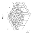
Fig. 1 is a perspective view of a battery module having a battery temperature regulator according to an embodiment of the present invention; -
Fig. 2 is a sectional view of a heat exchanger of the battery temperature regulator ofFig. 1 ; and -
Fig. 3 is a sectional view of another embodiment of the battery module. - The following will describe a battery module having a battery temperature regulator according to the embodiment of the present invention with reference to
Figs. 1 and2 . Referring toFig. 1 , the battery module designated generally by 10 includes an assembledbattery 1 that is composed of eight rectangular batteries such as 11, 12 arranged in alignment with each other in the direction of thickness thereof or in Y-axis direction inFig. 1 . That is, the direction in which thebatteries 11, 12 are arranged is the same as the direction of thickness of thebatteries 11, 12. Thebatteries 11,12 are the same in structure, but designated by different reference numerals for the sake of explanation. The adjacent twobatteries 11, 12 form onebattery group 13. In thebattery group 13, thebatteries 11, 12 correspond to the plural battery cells of the present invention. In the present embodiment, fourbattery groups 13 are integrated to form the assembledbattery 1. - In the assembled
battery 1, each of thebatteries 11, 12 has on the upper surface thereof apositive terminal 14 and anegative terminal 15 projecting upward or in Z-axis direction inFig. 1 . Thepositive terminal 14 and thenegative terminal 15 are spaced from each other in the direction of width of thebatteries 11,12 or in X-axis direction inFig. 1 . Thebatteries 11, 12 discharge through their respective positive andnegative terminals - In the present embodiment, three assembled batteries such as 1 are arranged in the direction of width of the
batteries 11, 12 in contact with each other. In other words, plural assembled batteries are arranged in the direction perpendicular to the alignment of thebatteries 11, 12. In the following description, the three assembled batteries are designated bydifferent reference numerals - The following will describe in detail the
battery temperature regulator 20 provided for the assembledbatteries battery temperature regulator 20 includesplural heat exchangers 21, asupply pipe 22 and adischarge pipe 23. Theheat exchanger 21 is in the form of a rectangular plate. In the adjacent threebattery groups 13 arranged in the X-axis direction, the three batteries 11 cooperate with their associated threebatteries 12 to hold therebetween thesame heat exchanger 21. That is, theheat exchanger 21 is provided between the battery cells. In the present embodiment, each of the assembledbatteries battery groups 13 and hence has fourheat exchangers 21. - The height of the
heat exchanger 21 as measured in the Z-axis direction is substantially the same as that of thebatteries 11, 12, and the width of theheat exchanger 21 as measured in the X-axis direction is approximately three times as large as that of therespective batteries 11, 12. That is, the width of theheat exchanger 21 is set depending on the number of assembledbatteries same heat exchanger 21 is held in common in theadjacent battery groups 13 arranged in the X-axis direction. - Heat medium such as water, air or organic solvent is supplied through the
supply pipe 22 to theheat exchangers 21 and then discharged out of theheat exchangers 21 through thedischarge pipe 23. Thesupply pipe 22, thedischarge pipe 23 correspond to the supply portion and the discharge portion, respectively, of the present invention. Thesupply pipe 22 and thedischarge pipe 23 extend in the direction of the alignment of thebatteries 11, 12. - The
heat exchanger 21 has on the upper surface thereof a pair of ring-shaped supports supply pipe 22 and thedischarge pipe 23 are inserted and supported respectively. - The
support 25 is formed at a position between thepositive terminals 14 and thenegative terminals 15 of therespective batteries 11, 12 of the assembledbattery 1. Thesupport 26 is formed at a position between thepositive terminals 14 and thenegative terminals 15 of therespective batteries 11, 12 of the assembledbattery 3. - The
supply pipe 22 supported by thesupport 25 is provided between thepositive terminals 14 and thenegative terminals 15 of therespective batteries 11, 12 of the assembledbattery 1. Thedischarge pipe 23 supported by thesupport 26 is provided between thepositive terminals 14 and thenegative terminals 15 of therespective batteries 11, 12 of the assembledbattery 3. - The
supply pipe 22 is mounted to theheat exchanger 21 while being supported by thesupport 25. Thedischarge pipe 23 is mounted to theheat exchanger 21 while being supported by thesupport 26. Thesupply pipe 22 and thedischarge pipe 23 form a part of theheat exchanger 21. - As described above, the
supply pipe 22 extending in the Y-axis direction is provided between thepositive terminals 14 and thenegative terminals 15 of thebatteries 11, 12 of the assembledbattery 1. Thedischarge pipe 23 extending in the Y-axis direction is provided between thepositive terminals 14 and thenegative terminals 15 of thebatteries 11, 12 of the assembledbattery 3. In other words, thebatteries 11, 12 forming the assembledbattery 1 are arranged in the direction in which thesupply pipe 22 extends, and thebatteries 11, 12 forming the assembledbattery 3 are arranged in the direction in which thedischarge pipe 23 extends. It is noted that thesupply pipe 22 or thedischarge pipe 23 may extend in a direction that is slightly inclined to the direction in which thebatteries 11, 12 are arranged. - The assembled
battery 1 and the assembledbattery 3 are provided on opposite sides of thebattery module 10. That is, thesupply pipe 22 and thedischarge pipe 23 are provided on the assembled batteries which are spaced away from each other. Thesupply pipe 22 is connected to theheat exchangers 21 at a position between thepositive terminals 14 and thenegative terminals 15 of therespective batteries 11, 12 of the assembledbattery 1. Thedischarge pipe 23 is connected to theheat exchangers 21 at a position between thepositive terminals 14 and thenegative terminals 15 of therespective batteries 11, 12 of the assembledbattery 3. - As shown in
Fig. 2 , thesupply pipe 22 is formed therethrough with ahole 22A, and thedischarge pipe 23 is formed therethrough with ahole 23A. - The
heat exchanger 21 hasholes holes hole 22A and thehole 21A connect between the interior of theheat exchanger 21 and the interior of thesupply pipe 22. Thehole 23A and thehole 21 B connect between the interior of theheat exchanger 21 and the interior of thedischarge pipe 23. - Although not shown in the drawings, heat medium is supplied from a heat medium source to the
supply pipe 22 and heat medium discharged from thedischarge pipe 23 is returned through a circulator passage back to the heat medium source. - The
supply pipe 22 and thedischarge pipe 23 of thebattery temperature regulator 20 are provided above thebatteries 11, 12. Thus, thebattery module 10 that is made by integrating the assembledbatteries battery temperature regulator 20 including theheat exchanger 21, thesupply pipe 22 and thedischarge pipe 23 causes no increase of the size of thebattery module 10 in the direction of width of thebatteries 11, 12. Thesupply pipe 22 is provided between thepositive terminals 14 and thenegative terminals 15 of thebatteries 11, 12 of the assembledbattery 1. Thedischarge pipe 23 is provided between thepositive terminals 14 and thenegative terminals 15 of thebatteries 11, 12 of the assembledbattery 3. Since thesupply pipe 22 and thedischarge pipe 23 are provided in the spaces between the positive andnegative terminals battery module 10 in the direction of height of thebatteries 11, 12 occurs. In this way, thebattery temperature regulator 20 of the embodiment causes no increase of the size of thebattery module 10 in the direction of width and height of thebatteries 11, 12, thereby allowing reduction of the size of thebattery module 10 as compared to the conventional case. - The
supply pipe 22 is provided between thepositive terminals 14 and thenegative terminals 15 of thebatteries 11, 12 of the assembledbattery 1. Thedischarge pipe 23 is provided between thepositive terminals 14 and thenegative terminals 15 of thebatteries 11, 12 of the assembledbattery 3. That is, thesupply pipe 22 is spaced away from thedischarge pipe 23. Heat medium flows in the interior of theheat exchanger 21 evenly, which facilitates stirring of heat medium in theheat exchanger 21, resulting in an efficient heat exchange for thebatteries 11, 12 disposed in contact with theheat exchanger 21. - Since the
heat exchangers 21 are provided between thebatteries 11, 12 of therespective battery groups 13 of the assembledbatteries batteries 11, 12 of the assembledbatteries heat exchangers 21. Thus, all of thebatteries 11, 12 are in contact with theheat exchangers 21 for heat exchange with the heat medium flowing through theheat exchangers 21, thereby allowing regulation of the temperature of allbatteries 11, 12. - The
battery temperature regulator 20 according to the first embodiment offers the following advantages. - (1) Each of the
batteries 11, 12 has on the upper surface thereof the positive andnegative terminals Fig. 1 . Thesupply pipe 22 is provided between thepositive terminals 14 and thenegative terminals 15 of thebatteries 11, 12 of the assembledbattery 1, and thedischarge pipe 23 is provided between thepositive terminals 14 and thenegative terminals 15 of thebatteries 11, 12 of the assembledbattery 3. Since thesupply pipe 22 and thedischarge pipe 23 are provided in the spaces between the positive andnegative terminals battery module 10 in the direction of height of thebatteries 11, 12 occurs. Further, thesupply pipe 22 and thedischarge pipe 23 of thebattery temperature regulator 20 are provided above thebatteries 11, 12, which causes no increase of the size of thebattery module 10 in the direction of width of thebatteries 11, 12. In this way, thebattery temperature regulator 20 of the embodiment causes no increase of the size of thebattery module 10 in the direction of width and height of thebatteries 11, 12, thereby allowing reduction of the size of thebattery module 10 as compared to the conventional case. - (2) The assembled
battery 1 is spaced away from the assembledbattery 3. Thesupply pipe 22 is spaced away from thedischarge pipe 23. Heat medium flows in the interior of theheat exchanger 21 evenly, which facilitates stirring of heat medium in theheat exchanger 21, resulting in an efficient heat exchange for thebatteries 11, 12 disposed in contact with theheat exchanger 21. - (3) The
heat exchangers 21 are provided between thebatteries 11, 12 of therespective battery groups 13 of the assembledbatteries batteries 11, 12 in the assembledbatteries heat exchangers 21, allowing proper regulation of the temperature of thebatteries 11, 12. - (4) In the adjacent three
battery groups 13 arranged in the X-axis direction, the three batteries 11 cooperate with their associated threebatteries 12 to hold therebetween thesame heat exchanger 21. Such configuration requires less number of heat exchangers such as 21, supply pipes such as 22 and discharge pipes such as 23 as compared to a case that theheat exchangers 21 are provided in all of thebattery groups 13 in the respective assembledbatteries battery module 10. - The above-described embodiment may be modified in various ways as exemplified below.
- As shown in
Fig. 3 , thebattery temperature regulator 20 may be provided in a single assembled battery such as 1 providing thesupply pipe 22 and thedischarge pipe 23 between thepositive terminals 14 and thenegative terminals 15 of the batteries such as 11,12 of the single assembled battery. In this case, the moving distance of heat medium in theheat exchanger 21 is decreased, which may lead to insufficient stirring of heat medium and hence remaining of heat medium after heat exchange in theheat exchanger 21. Thus, it is preferable to provide apartition wall 24 for dividing the interior of theheat exchanger 21, as shown inFig. 3 , so as to facilitate stirring of heat medium for proper heat exchanging. - Either one of the
supply pipe 22 and thedischarge pipe 23 only have to be provided between the positive andnegative terminals batteries 11, 12. In thebattery module 10, one of thesupply pipe 22 and thedischarge pipe 23 may be provided between the positive andnegative terminals batteries 11, 12 of the assembledbattery 1, while the other of thesupply pipe 22 and thedischarge pipe 23 may be provided, for example, on the side surfaces of thebatteries 11, 12 of the assembledbattery 3. - A spacer such as a resin spacer may be provided between the
batteries 11, 12 and theheat exchangers 21. - In each of the
batteries 11, 12 of the assembledbatteries positive terminal 14 and thenegative terminal 15 may be opposite. For example, the positions of thepositive terminal 14 and thenegative terminal 15 may be opposite inspecific batteries 11, 12 depending on the manner of connection of batteries in the assembledbatteries supply pipe 22 and thedischarge pipe 23 may be provided between thepositive terminals 14 or between thenegative terminals 15. - The number of
batteries 11, 12 of the respective assembledbatteries - The number of assembled
batteries - The
heat exchanger 21 only have to be provided between thebatteries 11, 12 of thesingle battery group 13, and the number ofheat exchangers 21 may be decreased or increased. - The
heat exchanger 21 may be provided between thebattery groups 13 arranged in the direction of thickness of thebatteries 11, 12. That is, theheat exchanger 21 may be provided between any twoadjacent batteries 11, 12. - Plural battery temperature regulators such as 20 may be provided for the respective assembled
batteries - The
supply pipe 22 and thedischarge pipe 23 may be provided between the positive andnegative terminals batteries supply pipe 22 may be provided between thenegative terminals 15 of thebatteries 11, 12 of the assembledbattery 1 and thepositive terminals 14 of thebatteries 11, 12 of the assembled battery 2, while thedischarge pipe 23 may be provided between thenegative terminals 15 of thebatteries 11, 12 of the assembled battery 2 and thepositive terminals 14 of thebatteries 11, 12 of the assembledbattery 3. - Although the
supply pipe 22 and thedischarge pipe 23 are supported by thesupports heat exchanger 21, theheat exchanger 21, thesupply pipe 22 and thedischarge pipe 23 may be formed integrally. - A battery temperature regulator is provided for use with an assembled battery in which plural battery cells are arranged in alignment with each other and each of the battery cells has positive and negative terminals projecting therefrom in the same direction. The battery temperature regulator includes a heat exchanger provided between the battery cells, a supply portion through which heat medium is supplied to the heat exchanger, and a discharge portion through which heat medium is discharged out of the heat exchanger. The supply portion and the discharge portion extend in the direction of the alignment of the battery cells. At least one of the supply portion and the discharge portion is provided between the positive terminals and the negative terminals of the battery cells.
Claims (3)
- A battery temperature regulator (20) for use with an assembled battery (1) in which plural battery cells (11, 12) are arranged in alignment with each other and each of the battery cells (11, 12) has positive and negative terminals (14, 15) projecting therefrom in the same direction, comprising:a heat exchanger (21) provided between the battery cells (11, 12);a supply portion (22) through which heat medium is supplied to the heat exchanger (21), the supply portion (22) extending in the direction of the alignment of the battery cells (11, 12); anda discharge portion (23) through which heat medium is discharged out of the heat exchanger (21), the discharge portion (23) extending in the direction of the alignment of the battery cells (11, 12),characterized in that at least one of the supply portion (22) and the discharge portion (23) is provided between the positive terminals (14) and the negative terminals (15) of the battery cells (11, 12).
- The battery temperature regulator (20) according to claim 1, wherein both of the supply portion (22) and the discharge portion (23) are provided between the positive and negative terminals (14, 15) of the battery cells (11, 12) of the same assembled battery (1).
- The battery temperature regulator (20) according to claim 1, wherein plural assembled batteries (1, 2, 3) are arranged in the direction perpendicular to the alignment of the battery cells (11, 12), the supply portion (22) is provided between the positive and negative terminals (14, 15) of the battery cells (11, 12) of one assembled battery (1), the discharge portion (23) is provided between the positive and negative terminals (14, 15) of the battery cells (11, 12) of another assembled battery (3).
Applications Claiming Priority (1)
| Application Number | Priority Date | Filing Date | Title |
|---|---|---|---|
| JP2011148339A JP5353961B2 (en) | 2011-07-04 | 2011-07-04 | Battery temperature control mechanism |
Publications (1)
| Publication Number | Publication Date |
|---|---|
| EP2544294A1 true EP2544294A1 (en) | 2013-01-09 |
Family
ID=46397091
Family Applications (1)
| Application Number | Title | Priority Date | Filing Date |
|---|---|---|---|
| EP20120174560 Withdrawn EP2544294A1 (en) | 2011-07-04 | 2012-07-02 | Arrangement for regulating the temperature of a battery |
Country Status (3)
| Country | Link |
|---|---|
| US (1) | US20130011712A1 (en) |
| EP (1) | EP2544294A1 (en) |
| JP (1) | JP5353961B2 (en) |
Cited By (2)
| Publication number | Priority date | Publication date | Assignee | Title |
|---|---|---|---|---|
| CN105762311A (en) * | 2016-04-07 | 2016-07-13 | 苏州工业园区职业技术学院 | Cooling shell used for power battery |
| FI131317B1 (en) * | 2021-02-03 | 2025-02-17 | Aurora Powertrains Oy | Scalably structurable battery pack |
Families Citing this family (4)
| Publication number | Priority date | Publication date | Assignee | Title |
|---|---|---|---|---|
| JP5751190B2 (en) * | 2012-02-20 | 2015-07-22 | 株式会社デンソー | Battery pack |
| DE102018222279A1 (en) * | 2018-12-19 | 2020-06-25 | Bayerische Motoren Werke Aktiengesellschaft | Accumulator arrangement |
| US11342620B2 (en) * | 2019-03-04 | 2022-05-24 | Chongqing Jinkang Powertrain New Energy Co., Ltd. | Battery module scalable in three dimensions |
| FR3113336B1 (en) * | 2020-08-06 | 2023-02-24 | Total Se | Device for cooling two electrochemical cells, electrochemical assembly and corresponding method |
Citations (4)
| Publication number | Priority date | Publication date | Assignee | Title |
|---|---|---|---|---|
| EP0596794A1 (en) * | 1992-11-02 | 1994-05-11 | Compagnie Europeenne D'accumulateurs | Heat-regulated accumulators battery, in particular for electric vehicle |
| US20070087266A1 (en) * | 2005-10-18 | 2007-04-19 | Debbi Bourke | Modular battery system |
| JP2008305575A (en) | 2007-06-05 | 2008-12-18 | Denso Corp | Battery temperature control device |
| EP2405527A1 (en) * | 2010-07-05 | 2012-01-11 | ads-tec GmbH | Battery block with a cooling device |
Family Cites Families (4)
| Publication number | Priority date | Publication date | Assignee | Title |
|---|---|---|---|---|
| FR2779872B1 (en) * | 1998-06-11 | 2000-08-04 | Alsthom Cge Alcatel | MONOBLOCK BATTERY COMPRISING A THERMAL EXCHANGE DEVICE BY CIRCULATION OF A FLUID |
| JP2009054297A (en) * | 2007-08-23 | 2009-03-12 | Toshiba Corp | Battery pack |
| JP2011029103A (en) * | 2009-07-29 | 2011-02-10 | Kawasaki Shipbuilding Corp | Battery cooling device |
| JP5252082B2 (en) * | 2010-04-16 | 2013-07-31 | トヨタ自動車株式会社 | Power storage device |
-
2011
- 2011-07-04 JP JP2011148339A patent/JP5353961B2/en not_active Expired - Fee Related
-
2012
- 2012-06-29 US US13/537,238 patent/US20130011712A1/en not_active Abandoned
- 2012-07-02 EP EP20120174560 patent/EP2544294A1/en not_active Withdrawn
Patent Citations (4)
| Publication number | Priority date | Publication date | Assignee | Title |
|---|---|---|---|---|
| EP0596794A1 (en) * | 1992-11-02 | 1994-05-11 | Compagnie Europeenne D'accumulateurs | Heat-regulated accumulators battery, in particular for electric vehicle |
| US20070087266A1 (en) * | 2005-10-18 | 2007-04-19 | Debbi Bourke | Modular battery system |
| JP2008305575A (en) | 2007-06-05 | 2008-12-18 | Denso Corp | Battery temperature control device |
| EP2405527A1 (en) * | 2010-07-05 | 2012-01-11 | ads-tec GmbH | Battery block with a cooling device |
Cited By (2)
| Publication number | Priority date | Publication date | Assignee | Title |
|---|---|---|---|---|
| CN105762311A (en) * | 2016-04-07 | 2016-07-13 | 苏州工业园区职业技术学院 | Cooling shell used for power battery |
| FI131317B1 (en) * | 2021-02-03 | 2025-02-17 | Aurora Powertrains Oy | Scalably structurable battery pack |
Also Published As
| Publication number | Publication date |
|---|---|
| JP5353961B2 (en) | 2013-11-27 |
| JP2013016355A (en) | 2013-01-24 |
| US20130011712A1 (en) | 2013-01-10 |
Similar Documents
| Publication | Publication Date | Title |
|---|---|---|
| US20130011712A1 (en) | Battery temperature regulator | |
| US9166262B2 (en) | Battery pack with cooling passage | |
| CN106558659B (en) | Battery pack and vehicle having the same | |
| US9520626B2 (en) | Expandable stacked plate heat exchanger for a battery unit | |
| JP7011041B2 (en) | Fuel cell unit with angle offset flow channel | |
| JP5268044B2 (en) | Fuel cell | |
| KR20140020885A (en) | Manifold assembly for controlling gas flow and flow distribution in a fuel cell stack | |
| US20150280040A1 (en) | Heat exchanger for photovoltaic panels | |
| JP2005116342A (en) | Assembled battery | |
| US20080124620A1 (en) | Holder for cooling battery modules | |
| CN104755869A (en) | Stacked-plate heat exchanger with single plate design | |
| CN107482275A (en) | The register and battery module of battery module | |
| CN213845388U (en) | Battery module with air cooling structure and battery module frame thereof | |
| JP2009021050A (en) | Fuel cell | |
| CN109724432B (en) | Heat Exchangers for Internal Combustion Engines | |
| WO2017154071A1 (en) | Battery device | |
| CN219917309U (en) | Shunt assembly, thermal management system and battery pack | |
| KR20130078167A (en) | Heat exchanger for reactor | |
| EP3023727B1 (en) | Fluid guide plate and associated plate heat exchanger | |
| CN219575696U (en) | Fuel cell stack | |
| JP2022078644A (en) | Battery module and battery unit | |
| JP2016131209A (en) | Laminated unit | |
| CN219739073U (en) | Cooling assembly, battery pack and vehicle | |
| CN218975559U (en) | Energy storage system | |
| CN218731307U (en) | Battery device |
Legal Events
| Date | Code | Title | Description |
|---|---|---|---|
| PUAI | Public reference made under article 153(3) epc to a published international application that has entered the european phase |
Free format text: ORIGINAL CODE: 0009012 |
|
| 17P | Request for examination filed |
Effective date: 20120702 |
|
| AK | Designated contracting states |
Kind code of ref document: A1 Designated state(s): AL AT BE BG CH CY CZ DE DK EE ES FI FR GB GR HR HU IE IS IT LI LT LU LV MC MK MT NL NO PL PT RO RS SE SI SK SM TR |
|
| AX | Request for extension of the european patent |
Extension state: BA ME |
|
| 17Q | First examination report despatched |
Effective date: 20140114 |
|
| STAA | Information on the status of an ep patent application or granted ep patent |
Free format text: STATUS: THE APPLICATION IS DEEMED TO BE WITHDRAWN |
|
| 18D | Application deemed to be withdrawn |
Effective date: 20140527 |