EP2544014A1 - A method of selecting between faulted and healthy circuits in parallel lines using one-end measurements - Google Patents
A method of selecting between faulted and healthy circuits in parallel lines using one-end measurements Download PDFInfo
- Publication number
- EP2544014A1 EP2544014A1 EP11460033A EP11460033A EP2544014A1 EP 2544014 A1 EP2544014 A1 EP 2544014A1 EP 11460033 A EP11460033 A EP 11460033A EP 11460033 A EP11460033 A EP 11460033A EP 2544014 A1 EP2544014 A1 EP 2544014A1
- Authority
- EP
- European Patent Office
- Prior art keywords
- fault
- line
- parallel lines
- phase
- determination
- Prior art date
- Legal status (The legal status is an assumption and is not a legal conclusion. Google has not performed a legal analysis and makes no representation as to the accuracy of the status listed.)
- Withdrawn
Links
- 238000000034 method Methods 0.000 title claims abstract description 31
- 238000005259 measurement Methods 0.000 title claims abstract description 19
- 238000004364 calculation method Methods 0.000 claims abstract description 7
- 238000012545 processing Methods 0.000 claims abstract description 6
- 230000001681 protective effect Effects 0.000 claims description 16
- 238000004590 computer program Methods 0.000 claims description 4
- 230000005540 biological transmission Effects 0.000 abstract description 10
- 238000001914 filtration Methods 0.000 description 6
- 238000007405 data analysis Methods 0.000 description 5
- 238000004891 communication Methods 0.000 description 4
- 238000001514 detection method Methods 0.000 description 2
- 238000013459 approach Methods 0.000 description 1
- 239000003990 capacitor Substances 0.000 description 1
- 238000006243 chemical reaction Methods 0.000 description 1
- 238000007796 conventional method Methods 0.000 description 1
- 230000000694 effects Effects 0.000 description 1
- 230000002708 enhancing effect Effects 0.000 description 1
- 238000004904 shortening Methods 0.000 description 1
- 230000009469 supplementation Effects 0.000 description 1
Images


Classifications
-
- G—PHYSICS
- G01—MEASURING; TESTING
- G01R—MEASURING ELECTRIC VARIABLES; MEASURING MAGNETIC VARIABLES
- G01R31/00—Arrangements for testing electric properties; Arrangements for locating electric faults; Arrangements for electrical testing characterised by what is being tested not provided for elsewhere
- G01R31/08—Locating faults in cables, transmission lines, or networks
- G01R31/088—Aspects of digital computing
-
- G—PHYSICS
- G01—MEASURING; TESTING
- G01R—MEASURING ELECTRIC VARIABLES; MEASURING MAGNETIC VARIABLES
- G01R31/00—Arrangements for testing electric properties; Arrangements for locating electric faults; Arrangements for electrical testing characterised by what is being tested not provided for elsewhere
- G01R31/08—Locating faults in cables, transmission lines, or networks
- G01R31/081—Locating faults in cables, transmission lines, or networks according to type of conductors
- G01R31/085—Locating faults in cables, transmission lines, or networks according to type of conductors in power transmission or distribution lines, e.g. overhead
Definitions
- the present invention relates to a selection between faulted and healthy circuits in parallel lines with the use of one-end measurements in electric power lines, applicable to parallel power lines, fit for use in the power industry for overhead transmission lines.
- SC Series compensation
- the present practice relies on using traditional distance relays but with modified settings. Considerable shortening of the first zone reach to 30-40% instead of 85% is applied.
- the disadvantage of this method is that it requires the use of mutual impedance which is not uniformly distributed or known.
- the invented method does not use mutual impedance.
- the invented method is designed to allow selection between faulted and healthy circuits in parallel lines.
- the input signals in the method are samples of three-phase currents from both circuits of the parallel lines. Due to the applied specific kind of measurements the delivered method is considered to be a simple and important supplementation of the distance relay protection of parallel lines aimed at fast switching-off of the faulty line.
- the invented method can be used for both series compensated and uncompensated parallel transmission lines and it is also applicable in cases where one of the parallel lines works as series compensated and the other line of the parallel lines works as uncompensated.
- the subject of the inventive method using measurement of current signals at one end of the line in terminal A or in terminal B, processing the measuring data, determination of the pre-fault and fault current signals and the zero-sequence current signal, obtaining current phasors (I A1 , I B1 , I C1 , I A2 , I B2 , I C2 , I 01 , I 02 ) consists in that the method further comprises the steps of:
- a computer program product comprising a computer program code which when executed on a data processor unit of a protective device carries out the steps of the method according to claims 1-2.
- the subject of the inventive system having a protective device with a processor located at one end of the parallel lines and with a functional module for storing data delivered from an on-line measurement, with a calculating module for doing calculation operations and with an information module for presenting the result of the inventive method, is that the protective device has a selection module for performing the actions according to any of the method claims.
- the protective device has a form of a protective relay.
- the inventive method is used in a protective device having the form of a protective relay.
- a real-time digital current signal coming from current transformers and converted in an A/D converter into a digital signal compatible with IEC 61850 standard, is transmitted by the IEC 61850 9-2 protocol or any other communication protocol.
- the conversion of analogue phase current signals with the aid of the current instrument transformer CT's allows to obtain sampled discrete time values.
- interconnection by means of a station communication protocol preferably compatible with the IEC 61850 standard should be regarded as conventional techniques and have therefore been omitted.
- the present invention relates to a method for selecting between internal and external faults in parallel lines using one-end current signal measurements from both circuits of the parallel lines. Thanks to the inventive approach high reliability of identification of internal and external faults in parallel lines with the use of one-end measurements is achieved.
- FIG. 1 shows the schematic system for selecting between internal and external faults in parallel lines with the use of one-end measurements
- fig. 2 the inventive part of the system for selecting between internal and external faults in parallel lines with the use of one-end measurements in a protection relay
- fig. 3 a set of steps for the realisation of the inventive method.
- Line #1 and Line #2 current transformers 1 are connected with a protective device 2, having a form of a protection relay, by an analogue wire link 3 or by means of a process communication bus 4 containing a Margin Unit 5.
- the protection relay 2 with a data processing unit P comprises an A/D converter 6 and an arrangement of functional modules M1, M2, M3, M4 where the module M1 is a buffer module for storing data delivered from an on-line measurement, the module M2 is the module of selection between internal and external faults, the module M3 is a calculating module connecting with the others modules, and the module M4 is an information module for giving the result of the inventive method.
- the A/D converter 6 may be located in the Margin Unit 5 instead of being in the protection relay 2, which is indicated on the drawing by the dotted line.
- the protection relay 2 comprises other modules which are essential for the proper operation of the protection relay and which are not described in the description, and not presented in the fig. 1 .
- the module M2 of the selection between internal and external faults in parallel lines, presented in fig. 2 comprises a pre-filtering block B1 for filtering digital current signals, a data analysis block B2 for processing digital current signals, and a decision block B3 for selecting between internal and external faults in the parallel lines.
- the method according to the invention is carried out in the following steps:
- Step S1 real-time analog current signals I AL1 , I BL1 , I CL1 , I AL2 , I BL2 , I CL2 from the individual phases A, B, C from both circuit of the parallel lines Line #1 and Line #2 and optional zero sequences currents of both circuits of the parallel lines I 0L1 , I 0L2 are measured in the current transformers.
- the measured data are converted in an A/D converter to digital current signals i A1 , i B1 , i C1 , i A2 , i B2 , i C2 , i 01 , i 02 . and stored in the buffer module M1 of the protection relay.
- step S2 in the pre-filtering block B1 digital current signals from individual phases i A1 , i B1 , i C1 , i A2 , i B2 , i C2 of both circuit of the parallel lines and zero sequences currents i 01 , i 02 are filtered using one of the known methods of half-period filtering, for example the half-period window Fourier filter method, in order to obtain the phasor value of digital current signals I A1 , I B1 , I C1 , I A2 , I B2 , I C2 for each individual phase A, B, C of both circuits of the parallel lines , which are represented by magnitude and phase angle.
- zero sequences digital currents I 0L1 , I 0L2 of both circuits of the parallel lines are filtered in order to obtain the phasor value I 01 and I 02 .
- step S3 having the phasor value of digital current signals I A1 , I B1 , I C1 , I A2 , I B2 , I C2 , the pre-fault current signals I A1pre , I B1pre , I C1pre , I A2pre , I B2pre , I C2pre , I 01pre , I 02pre , and fault current signals I FA1 , I FB1 , I FC1 , I FA2 , I FB2 , I FC2 , I F01 , I F02 are determined using any of the known method, with the use of the fault detection time t F delivered in step 1.
- the pre-fault current signals are determined using the one period length pre-fault current signals in the pre-filtering block B1.
- k prefault I ABC ⁇ 1 ⁇ pre I ABC ⁇ 2 ⁇ pre
- STEP 5 Calculation of the difference values of the corrected fault during the fault.
- the corrected values of current phasors I A1f , I B1f , I C1f , I A2f , I B2f , I C2f are determined assuming that fault currents from one of the line (Line #1 or Line #2) are taken as reference corrected values of current phasors according to the following formulas:
- step 6 having the difference values of the corrected fault current di A1 , di B1 , di C1 , di 01 , di A2 , di B2 , di C2 , di 02 , the sums of the current differences sdi 1 , sdi 01 , sdi 2 , sdi 02 are calculated in the data analysis block B2 according to the following formulas:
- step S7 having the sum of the current differences sdi 1 , sdi 01 , sd i2 , sdi 02 the fault f 1 , f i01 , f 2 , f 02 coefficients are calculated according to the following formulas:
- the value of the flag ff 1 , and ff 2 zero or one is a conventional value and the inverse possibility of the selection is contained in the scope of the invention.
- flags ff 1 , ff 2 available in each of the modules M1...M4 are transmitted to the display or to printing devices which are connected with one of the modules and which are not shown in the drawing. This information is presented to the user of the protective device 2 and is further processed in order to assure the reliable operation of the protective device 2.
Landscapes
- Physics & Mathematics (AREA)
- Engineering & Computer Science (AREA)
- Mathematical Physics (AREA)
- Theoretical Computer Science (AREA)
- General Physics & Mathematics (AREA)
- Emergency Protection Circuit Devices (AREA)
Abstract
The present invention is concerned with a selection between faulted and healthy circuits in parallel lines, using one-end measurements in electric power lines, applicable to parallel power lines, fit for use in the power industry for overhead transmission lines. The subject of the inventive method using measurement of current signals at one end of the line in terminal A or in terminal B, processing measuring data, determination of pre-fault and fault current signals and the zero-sequence current signal, obtaining current phasors (IA1, IB1, IC1, IA2, IB2, IC2, I01, I02), consists in that the method further comprises the steps of:
-determination of a symmetrical scaling coefficient (kprefault ) establishing a reciprocal relation between the currents of a single line of the parallel lines,
- determination of the corrected fault current phasors after scaling and calculation of current differences sum for each line (sdi1, sdi01, sdi2, sdi02),
- determination of fault f1 , fi01, f2, f02 coefficients ,
- determination of the value of flags ff1 and ff2 having a conventional value one or zero and a selection of faulted and healthy circuits in the parallel lines.
-determination of a symmetrical scaling coefficient (kprefault ) establishing a reciprocal relation between the currents of a single line of the parallel lines,
- determination of the corrected fault current phasors after scaling and calculation of current differences sum for each line (sdi1, sdi01, sdi2, sdi02),
- determination of fault f1 , fi01, f2, f02 coefficients ,
- determination of the value of flags ff1 and ff2 having a conventional value one or zero and a selection of faulted and healthy circuits in the parallel lines.
Description
- The present invention relates to a selection between faulted and healthy circuits in parallel lines with the use of one-end measurements in electric power lines, applicable to parallel power lines, fit for use in the power industry for overhead transmission lines.
- Series compensation (SC) is applied to worldwide EHV transmission lines where long transmission distance and large power transmission are involved. It is an effective and economic means of increasing power transmission capability, improving power system stability, reducing transmission losses, enhancing voltage control and flexible power flow control.
- However, protection of such kind of line still causes problems especially for parallel lines. This is due to the fact that series capacitors shift the fault-loop impedances which results in tripping the healthy line. Additionally, the currently used algorithms aimed at identifying the fault direction maloperate in the case of inversion of voltage and current signals.
- To avoid such misoperation, the present practice relies on using traditional distance relays but with modified settings. Considerable shortening of the first zone reach to 30-40% instead of 85% is applied.
- An example of a current application for detecting the position of a fault on a parallel lines link is described in the
US patent 4525098 . This application is based on determination of the fault direction in the protection relays located at each end of the parallel lines . If both relays located in one of the circuits of the parallel lines indicate the same forward fault direction, this circuit of the parallel lines is declared to be the faulted one. - Another example of a method for fault location in the parallel transmission lines with series compensation is described in
US patent 6476613 . In this solution the zero sequence current measurement is used to compensate the mutual impedance effect in distance-to-fault calculation. - The disadvantage of this method is that it requires the use of mutual impedance which is not uniformly distributed or known. The invented method does not use mutual impedance.
- The invented method is designed to allow selection between faulted and healthy circuits in parallel lines. The input signals in the method are samples of three-phase currents from both circuits of the parallel lines. Due to the applied specific kind of measurements the delivered method is considered to be a simple and important supplementation of the distance relay protection of parallel lines aimed at fast switching-off of the faulty line.
- The invented method can be used for both series compensated and uncompensated parallel transmission lines and it is also applicable in cases where one of the parallel lines works as series compensated and the other line of the parallel lines works as uncompensated.
- The subject of the inventive method using measurement of current signals at one end of the line in terminal A or in terminal B, processing the measuring data, determination of the pre-fault and fault current signals and the zero-sequence current signal, obtaining current phasors (IA1, IB1, IC1, IA2, IB2, IC2, I01, I02) consists in that the method further comprises the steps of:
- determination of the symmetrical scaling coefficient (kprefault) establishing a reciprocal relation between the currents of the single line of the parallel lines,
- determination of the corrected fault current phasors after scaling and calculating the current differences sum for each line (sdi1, sdi01, sdi2, sdi02),
- determination of fault f1, fi01, f2, f02 coefficients
- determination of the value of flags ff1 and ff2 having a conventional value of one or zero in order to carry out the selection of faulted and healthy circuits in the parallel lines when the following conditions are fulfilled:
- for
Line # 1
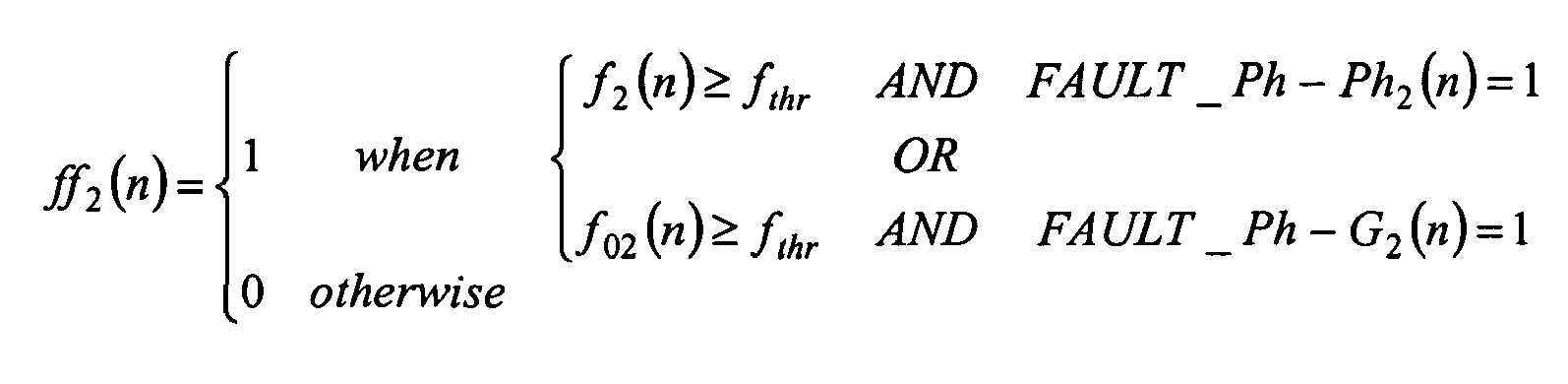
- fthr - threshold for fault coefficients f1, fi01, f2, f02
- FAULT_Ph - G1 (n) is a fault type coefficient indicating phase-to-ground faults and in the
line # 1 - FAULT_Ph - Ph1 (n) is a fault type coefficient indicating phase-to-phase fault in the
line # 1 or non-fault conditions, - FAULT_Ph - G2 (n) is a fault type coefficient indicating phase-to-ground faults and in the
line # 2, - FAULT_Ph - Ph2 (n) is a fault type coefficient indicating a phase-to-phase fault in the
line # 2 or non-fault conditions.
- for
- Next the selection is performed in the following actions.
First it is checked if only one of the flags ff1 or ff2 equals one, and if :
it means that the outside fault of the parallel lines has been identified.
Next the relation between the value of the ff1 and ff2 is checked, and if
it means that internal fault withinline # 1 of the parallel lines has been identified; or if
it means that internal fault withinline # 2 of the parallel lines has been identified. - In the embodiment of the invention the threshold for coefficients f1,fi01, f2, f02 was set to (fthr = 1.5).
- A computer program product comprising a computer program code which when executed on a data processor unit of a protective device carries out the steps of the method according to claims 1-2.
- The subject of the inventive system having a protective device with a processor located at one end of the parallel lines and with a functional module for storing data delivered from an on-line measurement, with a calculating module for doing calculation operations and with an information module for presenting the result of the inventive method, is that the protective device has a selection module for performing the actions according to any of the method claims.
Preferably the protective device has a form of a protective relay. - The inventive method is used in a protective device having the form of a protective relay. A real-time digital current signal coming from current transformers and converted in an A/D converter into a digital signal compatible with IEC 61850 standard, is transmitted by the IEC 61850 9-2 protocol or any other communication protocol. The conversion of analogue phase current signals with the aid of the current instrument transformer CT's allows to obtain sampled discrete time values. In this context, interconnection by means of a station communication protocol preferably compatible with the IEC 61850 standard should be regarded as conventional techniques and have therefore been omitted.
- The present invention relates to a method for selecting between internal and external faults in parallel lines using one-end current signal measurements from both circuits of the parallel lines. Thanks to the inventive approach high reliability of identification of internal and external faults in parallel lines with the use of one-end measurements is achieved.
- A method of selecting between internal and external faults in parallel lines is presented in the drawing, where
fig. 1 shows the schematic system for selecting between internal and external faults in parallel lines with the use of one-end measurements,fig. 2 - the inventive part of the system for selecting between internal and external faults in parallel lines with the use of one-end measurements in a protection relay,fig. 3 - a set of steps for the realisation of the inventive method. - In two parallel
lines Line # 1 andLine # 2current transformers 1 are connected with aprotective device 2, having a form of a protection relay, by ananalogue wire link 3 or by means of aprocess communication bus 4 containing aMargin Unit 5. Theprotection relay 2 with a data processing unit P comprises an A/D converter 6 and an arrangement of functional modules M1, M2, M3, M4 where the module M1 is a buffer module for storing data delivered from an on-line measurement, the module M2 is the module of selection between internal and external faults, the module M3 is a calculating module connecting with the others modules, and the module M4 is an information module for giving the result of the inventive method. In a case where theprotection relay 2 is connected by thecommunication bus 4, the A/D converter 6 may be located in the MarginUnit 5 instead of being in theprotection relay 2, which is indicated on the drawing by the dotted line. It is obvious that theprotection relay 2 comprises other modules which are essential for the proper operation of the protection relay and which are not described in the description, and not presented in thefig. 1 . The module M2 of the selection between internal and external faults in parallel lines, presented infig. 2 , comprises a pre-filtering block B1 for filtering digital current signals, a data analysis block B2 for processing digital current signals, and a decision block B3 for selecting between internal and external faults in the parallel lines. - The method according to the invention is carried out in the following steps:
- In Step S1, real-time analog current signals IAL1, IBL1, ICL1, IAL2, IBL2, ICL2 from the individual phases A, B, C from both circuit of the parallel
lines Line # 1 andLine # 2 and optional zero sequences currents of both circuits of the parallel lines I0L1, I0L2 are measured in the current transformers. Next, the measured data are converted in an A/D converter to digital current signals iA1, iB1, iC1, iA2, iB2, iC2, i01, i02. and stored in the buffer module M1 of the protection relay. - Additionally a fault type coefficient FAULT_Ph - G1 (n) indicating phase-to-ground faults and in the
line # 1 coefficient FAULT_Ph - Ph1 (n) indicating a phase-to-phase fault in theline # 1, coefficient FAULT_Ph - G2 (n) indicating phase-to-ground faults and in theline # 2 coefficient FAULT_Ph - Ph2 (n) indicating a phase-to-phase fault in theline # 2, and a fault detection time tF, are taken from other essential modules required for the proper operation of the protection relay. Also in this step a different current sum coefficient sdithr indicating a threshold value is delivered to the relay by the user. All of those coefficients are stored in the buffer module M1 of the protection relay. - If during the operation of the parallel lines, a phase-to-ground fault occurs in
line # 1, then the coefficient FAULT_Ph - G1 (n) =1 and the coefficient FAULT_Ph - Ph1 (n) = 0. If during the operation of the parallel lines a phase-to-phase fault occurs inline # 1 then the coefficient FAULT_Ph - G1 (n) = 0 and the coefficient FAULT_Ph - Ph1 (n) =1. When a phase-to-phase-to-ground fault occurs both FAULT_Ph - G1 (n) and FAULT_Ph - Ph1 (n) are set to 1. - If during the operation of the parallel lines, a phase-to-ground fault occurs in
line # 2, then the coefficient FAULT_Ph - G2 (n) =1 and the coefficient FAULT_Ph - Ph2 (n) = 0 . If during the operation of the parallel lines a phase-to-phase fault occurs inline # 1, then the coefficient FAULT_Ph - G2 (n) = 0 and the coefficient FAULT_Ph - Ph2 (n)=1. When a phase-to-phase-to-ground fault occurs, both FAULT_Ph - G2 (n) and FAULT_Ph - Ph2 (n) are set to 1. - Next, in step S2 in the pre-filtering block B1, digital current signals from individual phases i A1 , iB1, iC1, iA2, iB2, iC2 of both circuit of the parallel lines and zero sequences currents i01, i02 are filtered using one of the known methods of half-period filtering, for example the half-period window Fourier filter method, in order to obtain the phasor value of digital current signals I A1 , IB1, IC1, IA2, IB2, IC2 for each individual phase A, B, C of both circuits of the parallel lines , which are represented by magnitude and phase angle. Also zero sequences digital currents I0L1, I0L2 of both circuits of the parallel lines are filtered in order to obtain the phasor value I01 and I02. Alternatively, if the zero sequence currents I0L1 and I0L2 are not measured and delivered in
step 1, the phasor value of zero sequences digital currents I01, I02 can be calculated from the digital current signal according to the following formulas:

where: - IA1, IB1, IC1, - A, B, C phasor value of digital current signals in
Line # 1, - IA2, IB2, IC2,- A, B, C phasor value of digital current signals in
Line # 2. - In step S3, having the phasor value of digital current signals IA1, IB1, IC1, I A2, IB2, IC2, the pre-fault current signals I A1pre, IB1pre, IC1pre, IA2pre, IB2pre, IC2pre, I01pre, I02pre, and fault current signals IFA1, I FB1, I FC1, I FA2, IFB2, IFC2, IF01, IF02 are determined using any of the known method, with the use of the fault detection time tF delivered in
step 1. In the embodiment of the invention the pre-fault current signals are determined using the one period length pre-fault current signals in the pre-filtering block B1. - In step S4, first, having the pre-fault current signals IA1pre, IB1pre, IC1pre, IA2pre, IB2pre, IC2pre, the average values of 3-phase digital current signals magnitude IABC1pre, , IABC2pre, of both circuits of the parallel lines are calculated in the data analysis block B2 as:


- Next, the symmetrical scaling coefficient kprefault is determined according to the following formula:
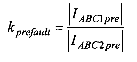
- In the step S5 in the data analysis block B2, the corrected values of current phasors I A1f, IB1f, IC1f, IA2f, IB2f, IC2f are determined assuming that fault currents from one of the line (
Line # 1 or Line #2) are taken as reference corrected values of current phasors according to the following formulas: - ● if the reference line is the
Line # 1 then:


where:- n- is the real consecutive number of the present digital sample processed by the relay
- ● if the reference line is the
Line # 2 then


where:- n- is the real consecutive number of the present digital sample processed by the relay.
- for Line #1:


- for
Line # 2


- In
step 6, having the difference values of the corrected fault current diA1, diB1, diC1, di01, diA2, diB2, diC2, di02, the sums of the current differences sdi1, sdi01, sdi2, sdi02 are calculated in the data analysis block B2 according to the following formulas: - for n=1 and for Line #1:


- for n=1 and for Line #2:


- for n>1 and for
Line # 1

- for n>1 for and Line #2:


- In step S7, having the sum of the current differences sdi1, sdi01, sdi2, sdi02 the fault f1, fi01, f2, f02 coefficients are calculated according to the following formulas:
- for Line #1:


- for Line #2:


- In the next step, having the fault f1, fi01, f2, f02 coefficients and coefficient the FAULT_Ph - G1 (n) indicating the phase to ground faults and in the
line # 1 the coefficient FAULT_Ph - Ph1 (n) indicating the phase-to-phase fault in theline # 1, the coefficient FAULT_Ph - G2 (n) indicating the phase-to-ground faults and in theline # 2 the coefficient FAULT_Ph - Ph2 (n) indicating the phase-to-phase fault in theline # 2, delivered inStep 1, flags ff1 and ff2 are calculated: - for
Line # 1
- and for Line #2:

- fthr - the threshold for fault coefficients f1, fi01, f2, f02,
- FAULT_Ph - G1 (n) is a fault type coefficient indicating phase-to-ground faults and in the
line # 1 - FAULT_Ph - Ph1 (n) is a fault type coefficient indicating phase-to-phase fault in the
line # 1, - FAULT_Ph - G2 (n) is a fault type coefficient indicating the phase-to-ground faults and in the
line # 2, - FAULT_Ph - Ph2 (n) is a fault type coefficient indicating the phase-to-phase fault in the
line # 2. - Next, it is checked if only one of the flags ff1 or ff2 equals one. This condition is described by the following equation:

it means that an outside fault of the parallel lines is identified;
when
it means that an internal fault withinline # 1 of the parallel lines is identified; when
it means that an internal fault withinline # 2 of the parallel lines has been identified. - In the embodiment of the invention, the threshold for coefficients f1, fi01, f2, f02 was set to (fthr = 1.5). This threshold is set according to the system configuration.
- The value of the flag ff 1, and ff 2 zero or one is a conventional value and the inverse possibility of the selection is contained in the scope of the invention.
- In the next step S9, flags ff 1, ff 2 available in each of the modules M1...M4 are transmitted to the display or to printing devices which are connected with one of the modules and which are not shown in the drawing. This information is presented to the user of the
protective device 2 and is further processed in order to assure the reliable operation of theprotective device 2.
Claims (5)
- A method for selecting between internal and external faults in parallel lines, using one-end measurements, where selection functions are implemented by a protective device (2) located at one end of the parallel lines, and where the method contains: measurement of current signals at one end of the line in terminal A or in terminal B, processing of measuring data, determination of pre-fault and fault current signals and the zero-sequence current signal, obtaining current phasors (IA1, IB1, IC1, IA2, IB2, IC2, I01, I02), characterised in that that the method further comprises the steps of:● determination of a symmetrical scaling coefficient (kprefault) establishing a reciprocal relation between the currents of a single line of the parallel lines,● determination of the corrected fault current phasors after scaling and calculation of current differences sum for each line (sdi1, sdi01, sdi2, sdi02),● determination of fault f1, fi01, f2, f02 coefficients,● determination a the value of flags ff 1 and ff 2, having the conventional value one or zero, in order to carry out the selection between faulted and healthy circuits in parallel lines when the following conditions are fulfilled:for Line #1:
 and for Line #2:where
 fthr - the threshold for fault coefficients f1, f01, f2, f02n - is the real consecutive number of the present digital sample processed by the protective device,FAULT_Ph - G1 (n) is a fault type coefficient indicating phase-to-ground faults and in the line #1FAULT_Ph - Ph1 (n) is a fault type coefficient indicating a phase-to-phase fault in the line #1,FAULT_Ph - G2 (n) is a fault type coefficient indicating phase-to-ground faults and in the line #2,FAULT_Ph - Ph2 (n) is a fault type coefficient indicating a phase-to-phase fault in the line #2and next a selection is performed in the following actions:- first it is checked if only one of the flags ff1 or ff2 equals one, and if :
it means that an outside fault of the parallel lines has been identified;- next the relation between the value of ff1 and ff2 is checked, and if
it means that an internal fault within line # 1 of the parallel lines has been identified;
or if
it means that an internal fault within line # 2 of the parallel lines has been identified.● automatic presentation of the results to the user by the protective device. - A method according to claim 1, characterised in that the symmetrical scaling coefficient kprefault is calculated in the following way:

where
IABC1pre, is the value of the positive sequence currents of one of the parallel lines,
IABC2pre is the value of the positive sequence currents of the other one of the parallel lines. - A computer program for selecting between faulted and healthy circuits in parallel lines using one-end measurements which is loadable into and executable on a data processing unit and which computer program, when being executed, performs the steps according to one of the preceding claims.
- A system for selecting between faulted and healthy circuits in parallel lines, using one-end measurements, having a protective device (2) with a processor (P), located at one end of the parallel lines and with a functional module (M1) for storing data delivered from an on-line measurement (M1), with a calculating module (M3) for doing calculation operations and with an information module (M4) for presenting the result of the inventive method, characterised in that the protective device (2) has a selection module (M2) for performing the actions according to any of the method claims, which is connected with the other modules (M1, M3, M4).
- A system according to claim 3, characterised in that the protective device (2) has a form of a protection relay.
Priority Applications (3)
| Application Number | Priority Date | Filing Date | Title |
|---|---|---|---|
| EP11460033A EP2544014A1 (en) | 2011-07-05 | 2011-07-05 | A method of selecting between faulted and healthy circuits in parallel lines using one-end measurements |
| PCT/EP2012/002694 WO2013004357A1 (en) | 2011-07-05 | 2012-06-26 | A method of selecting between internal and external faults in parallel lines using one-end measurements |
| PCT/EP2012/002715 WO2013004359A1 (en) | 2011-07-05 | 2012-06-27 | A method of selecting between faulted and healthy circuits in parallel lines using one-end measurements |
Applications Claiming Priority (1)
| Application Number | Priority Date | Filing Date | Title |
|---|---|---|---|
| EP11460033A EP2544014A1 (en) | 2011-07-05 | 2011-07-05 | A method of selecting between faulted and healthy circuits in parallel lines using one-end measurements |
Publications (1)
| Publication Number | Publication Date |
|---|---|
| EP2544014A1 true EP2544014A1 (en) | 2013-01-09 |
Family
ID=44645032
Family Applications (1)
| Application Number | Title | Priority Date | Filing Date |
|---|---|---|---|
| EP11460033A Withdrawn EP2544014A1 (en) | 2011-07-05 | 2011-07-05 | A method of selecting between faulted and healthy circuits in parallel lines using one-end measurements |
Country Status (1)
| Country | Link |
|---|---|
| EP (1) | EP2544014A1 (en) |
Cited By (8)
| Publication number | Priority date | Publication date | Assignee | Title |
|---|---|---|---|---|
| CN103760470A (en) * | 2014-02-18 | 2014-04-30 | 国家电网公司 | Electric transmission line inter-phase short circuit fault direction discriminating method based on discrete sampled values |
| CN104253420A (en) * | 2014-09-12 | 2014-12-31 | 西安交通大学 | Distance protection method for non-transposition double-circuit lines on same tower |
| CN105388390A (en) * | 2015-06-23 | 2016-03-09 | 河南理工大学 | Weak transient zero sequence current fault feature extraction method based on PSO (Particle Swarm Optimization) |
| CN105606955A (en) * | 2015-12-04 | 2016-05-25 | 云南电网公司楚雄供电局 | Numerical differentiation and empirical mode decomposition-based fault line distinguishing method |
| US9461458B2 (en) | 2011-08-16 | 2016-10-04 | Abb Technology Ag | Method of distance protection of parallel transmission line |
| CN108508280A (en) * | 2018-07-04 | 2018-09-07 | 国网山东省电力公司泰安供电公司 | Circuit Zero sequence parameter computational methods, device and electronic equipment |
| CN109596945A (en) * | 2019-01-18 | 2019-04-09 | 广东电网有限责任公司 | A kind of New Criterion of Faulty Line Detection for Distribution based on related coefficient vector similarity degree |
| US11428726B2 (en) | 2016-05-23 | 2022-08-30 | Emtele Oy | Method and apparatus for detecting faults in a three-phase electrical distribution network |
Citations (3)
| Publication number | Priority date | Publication date | Assignee | Title |
|---|---|---|---|---|
| US4525098A (en) | 1981-12-15 | 1985-06-25 | Werner Krude | Assembly for connecting together torque-transmitting members |
| US5661664A (en) * | 1994-02-28 | 1997-08-26 | Abb Power T&D Company Inc. | One-terminal data fault location system and process for locating a fault |
| US6476613B2 (en) | 2000-12-20 | 2002-11-05 | Abb Ab | Method of fault location in parallel transmission lines with series compensation |
-
2011
- 2011-07-05 EP EP11460033A patent/EP2544014A1/en not_active Withdrawn
Patent Citations (3)
| Publication number | Priority date | Publication date | Assignee | Title |
|---|---|---|---|---|
| US4525098A (en) | 1981-12-15 | 1985-06-25 | Werner Krude | Assembly for connecting together torque-transmitting members |
| US5661664A (en) * | 1994-02-28 | 1997-08-26 | Abb Power T&D Company Inc. | One-terminal data fault location system and process for locating a fault |
| US6476613B2 (en) | 2000-12-20 | 2002-11-05 | Abb Ab | Method of fault location in parallel transmission lines with series compensation |
Non-Patent Citations (2)
| Title |
|---|
| OSMAN A H ET AL: "Experimental test results for a parallel transmission lines protection scheme using wavelet transform", IEE PROCEEDINGS: GENERATION, TRANSMISSION AND DISTRIBUTION, INSTITUTION OF ELECTRICAL ENGINEERS, GB, vol. 151, no. 6, 12 November 2004 (2004-11-12), pages 713 - 720, XP006023081, ISSN: 1350-2360, DOI: 10.1049/IP-GTD:20041071 * |
| ZHANG QINGCHAO ET AL: "Fault Location of Two-parallel Transmission Line for Non-earth Fault Using One-terminal Data", IEEE TRANSACTIONS ON POWER DELIVERY, IEEE SERVICE CENTER, NEW YORK, NY, US, vol. 14, no. 3, 1 July 1999 (1999-07-01), pages 863 - 867, XP011089105, ISSN: 0885-8977, DOI: 10.1109/61.772325 * |
Cited By (11)
| Publication number | Priority date | Publication date | Assignee | Title |
|---|---|---|---|---|
| US9461458B2 (en) | 2011-08-16 | 2016-10-04 | Abb Technology Ag | Method of distance protection of parallel transmission line |
| CN103760470A (en) * | 2014-02-18 | 2014-04-30 | 国家电网公司 | Electric transmission line inter-phase short circuit fault direction discriminating method based on discrete sampled values |
| CN104253420A (en) * | 2014-09-12 | 2014-12-31 | 西安交通大学 | Distance protection method for non-transposition double-circuit lines on same tower |
| CN104253420B (en) * | 2014-09-12 | 2017-03-29 | 西安交通大学 | A kind of distance protecting method for the multiple-circuit on same tower that do not replace |
| CN105388390A (en) * | 2015-06-23 | 2016-03-09 | 河南理工大学 | Weak transient zero sequence current fault feature extraction method based on PSO (Particle Swarm Optimization) |
| CN105388390B (en) * | 2015-06-23 | 2018-06-29 | 河南理工大学 | Weak transient zero-sequence current fault signature extracting method based on particle group optimizing |
| CN105606955A (en) * | 2015-12-04 | 2016-05-25 | 云南电网公司楚雄供电局 | Numerical differentiation and empirical mode decomposition-based fault line distinguishing method |
| CN105606955B (en) * | 2015-12-04 | 2019-02-05 | 云南电网公司楚雄供电局 | A fault line identification method based on numerical differentiation and empirical mode decomposition |
| US11428726B2 (en) | 2016-05-23 | 2022-08-30 | Emtele Oy | Method and apparatus for detecting faults in a three-phase electrical distribution network |
| CN108508280A (en) * | 2018-07-04 | 2018-09-07 | 国网山东省电力公司泰安供电公司 | Circuit Zero sequence parameter computational methods, device and electronic equipment |
| CN109596945A (en) * | 2019-01-18 | 2019-04-09 | 广东电网有限责任公司 | A kind of New Criterion of Faulty Line Detection for Distribution based on related coefficient vector similarity degree |
Similar Documents
| Publication | Publication Date | Title |
|---|---|---|
| EP2544014A1 (en) | A method of selecting between faulted and healthy circuits in parallel lines using one-end measurements | |
| EP2474076B1 (en) | A method of fault phase selection and fault type determination | |
| EP2544322A1 (en) | A method of selecting between internal and external faults in parallel lines using one-end measurements | |
| US11022655B2 (en) | Method and control system for faulted phase detection | |
| EP2745367B1 (en) | A method of distance protection of parallel transmission line | |
| EP3088906B1 (en) | Fault location detection and distance protection apparatus and associated method | |
| US8183871B2 (en) | Method and device for fault location in a two-terminal transmission or distribution power line | |
| US20190146024A1 (en) | Fault location during pole-open condition | |
| RU2557017C2 (en) | Fault identification and directional detection in three-phase power system | |
| KR100350722B1 (en) | Apparatus and method for locating fault distance in a power double circuit transmision line | |
| EP3639337B1 (en) | Method and control system for fault direction detection | |
| WO2016180921A1 (en) | Improvements in or relating to direct current protection schemes | |
| EP3560054B1 (en) | A method for detecting inrush and ct saturation and an intelligent electronic device therefor | |
| CN110783895B (en) | Method for rapidly judging CT disconnection in optical fiber differential protection | |
| CN106257294A (en) | For the method and apparatus detecting the fault in electrical network | |
| EP2595264A1 (en) | Protection relay apparatus | |
| WO2013004359A1 (en) | A method of selecting between faulted and healthy circuits in parallel lines using one-end measurements | |
| JP3451552B2 (en) | Protection relay device for power system | |
| JP4490758B2 (en) | Accident identification device for power transmission system | |
| JPH09304468A (en) | Method for locating fault-point of parallel two line system | |
| EP3141918A1 (en) | Improvements in or relating to determining a fault location in a power transmission medium | |
| Choudry | POWER STREAM From |
Legal Events
| Date | Code | Title | Description |
|---|---|---|---|
| PUAI | Public reference made under article 153(3) epc to a published international application that has entered the european phase |
Free format text: ORIGINAL CODE: 0009012 |
|
| AK | Designated contracting states |
Kind code of ref document: A1 Designated state(s): AL AT BE BG CH CY CZ DE DK EE ES FI FR GB GR HR HU IE IS IT LI LT LU LV MC MK MT NL NO PL PT RO RS SE SI SK SM TR |
|
| AX | Request for extension of the european patent |
Extension state: BA ME |
|
| STAA | Information on the status of an ep patent application or granted ep patent |
Free format text: STATUS: THE APPLICATION IS DEEMED TO BE WITHDRAWN |
|
| 18D | Application deemed to be withdrawn |
Effective date: 20130710 |