EP2543985B1 - Numerical-experimental metodology to study the viscous behaviour of materials - Google Patents
Numerical-experimental metodology to study the viscous behaviour of materials Download PDFInfo
- Publication number
- EP2543985B1 EP2543985B1 EP11425153.1A EP11425153A EP2543985B1 EP 2543985 B1 EP2543985 B1 EP 2543985B1 EP 11425153 A EP11425153 A EP 11425153A EP 2543985 B1 EP2543985 B1 EP 2543985B1
- Authority
- EP
- European Patent Office
- Prior art keywords
- test
- bending
- specimen
- experimental
- numerical
- Prior art date
- Legal status (The legal status is an assumption and is not a legal conclusion. Google has not performed a legal analysis and makes no representation as to the accuracy of the status listed.)
- Not-in-force
Links
- 239000000463 material Substances 0.000 title claims description 53
- 238000012360 testing method Methods 0.000 claims description 88
- 238000005452 bending Methods 0.000 claims description 66
- 238000000034 method Methods 0.000 claims description 23
- 238000004458 analytical method Methods 0.000 claims description 9
- 229910010293 ceramic material Inorganic materials 0.000 claims description 9
- 230000003287 optical effect Effects 0.000 claims description 7
- 238000006073 displacement reaction Methods 0.000 claims description 4
- 238000000280 densification Methods 0.000 claims description 3
- 238000009434 installation Methods 0.000 claims description 3
- 230000001133 acceleration Effects 0.000 claims description 2
- 230000005484 gravity Effects 0.000 claims description 2
- 230000000295 complement effect Effects 0.000 claims 1
- 238000005245 sintering Methods 0.000 description 10
- 238000004088 simulation Methods 0.000 description 8
- 238000010304 firing Methods 0.000 description 7
- 238000013519 translation Methods 0.000 description 5
- 230000000694 effects Effects 0.000 description 4
- 238000002474 experimental method Methods 0.000 description 3
- 239000007787 solid Substances 0.000 description 3
- 239000011343 solid material Substances 0.000 description 3
- 239000000919 ceramic Substances 0.000 description 2
- 238000011161 development Methods 0.000 description 2
- 238000005259 measurement Methods 0.000 description 2
- 238000012512 characterization method Methods 0.000 description 1
- 230000002301 combined effect Effects 0.000 description 1
- 239000002131 composite material Substances 0.000 description 1
- 230000001010 compromised effect Effects 0.000 description 1
- 230000001419 dependent effect Effects 0.000 description 1
- 238000005516 engineering process Methods 0.000 description 1
- 238000003384 imaging method Methods 0.000 description 1
- 238000011835 investigation Methods 0.000 description 1
- 239000011148 porous material Substances 0.000 description 1
- 238000010206 sensitivity analysis Methods 0.000 description 1
Images





Classifications
-
- G—PHYSICS
- G01—MEASURING; TESTING
- G01N—INVESTIGATING OR ANALYSING MATERIALS BY DETERMINING THEIR CHEMICAL OR PHYSICAL PROPERTIES
- G01N11/00—Investigating flow properties of materials, e.g. viscosity, plasticity; Analysing materials by determining flow properties
-
- G—PHYSICS
- G01—MEASURING; TESTING
- G01N—INVESTIGATING OR ANALYSING MATERIALS BY DETERMINING THEIR CHEMICAL OR PHYSICAL PROPERTIES
- G01N3/00—Investigating strength properties of solid materials by application of mechanical stress
- G01N3/20—Investigating strength properties of solid materials by application of mechanical stress by applying steady bending forces
-
- G—PHYSICS
- G01—MEASURING; TESTING
- G01N—INVESTIGATING OR ANALYSING MATERIALS BY DETERMINING THEIR CHEMICAL OR PHYSICAL PROPERTIES
- G01N11/00—Investigating flow properties of materials, e.g. viscosity, plasticity; Analysing materials by determining flow properties
- G01N2011/006—Determining flow properties indirectly by measuring other parameters of the system
-
- G—PHYSICS
- G01—MEASURING; TESTING
- G01N—INVESTIGATING OR ANALYSING MATERIALS BY DETERMINING THEIR CHEMICAL OR PHYSICAL PROPERTIES
- G01N2203/00—Investigating strength properties of solid materials by application of mechanical stress
- G01N2203/0014—Type of force applied
- G01N2203/0023—Bending
-
- G—PHYSICS
- G01—MEASURING; TESTING
- G01N—INVESTIGATING OR ANALYSING MATERIALS BY DETERMINING THEIR CHEMICAL OR PHYSICAL PROPERTIES
- G01N2203/00—Investigating strength properties of solid materials by application of mechanical stress
- G01N2203/02—Details not specific for a particular testing method
- G01N2203/0202—Control of the test
- G01N2203/0206—Means for supplying or positioning specimens or exchangeable parts of the machine such as indenters...
-
- G—PHYSICS
- G01—MEASURING; TESTING
- G01N—INVESTIGATING OR ANALYSING MATERIALS BY DETERMINING THEIR CHEMICAL OR PHYSICAL PROPERTIES
- G01N2203/00—Investigating strength properties of solid materials by application of mechanical stress
- G01N2203/02—Details not specific for a particular testing method
- G01N2203/0202—Control of the test
- G01N2203/0212—Theories, calculations
- G01N2203/0216—Finite elements
-
- G—PHYSICS
- G01—MEASURING; TESTING
- G01N—INVESTIGATING OR ANALYSING MATERIALS BY DETERMINING THEIR CHEMICAL OR PHYSICAL PROPERTIES
- G01N2203/00—Investigating strength properties of solid materials by application of mechanical stress
- G01N2203/02—Details not specific for a particular testing method
- G01N2203/0202—Control of the test
- G01N2203/0212—Theories, calculations
- G01N2203/0218—Calculations based on experimental data
-
- G—PHYSICS
- G01—MEASURING; TESTING
- G01N—INVESTIGATING OR ANALYSING MATERIALS BY DETERMINING THEIR CHEMICAL OR PHYSICAL PROPERTIES
- G01N2203/00—Investigating strength properties of solid materials by application of mechanical stress
- G01N2203/02—Details not specific for a particular testing method
- G01N2203/022—Environment of the test
- G01N2203/0222—Temperature
- G01N2203/0226—High temperature; Heating means
-
- G—PHYSICS
- G01—MEASURING; TESTING
- G01N—INVESTIGATING OR ANALYSING MATERIALS BY DETERMINING THEIR CHEMICAL OR PHYSICAL PROPERTIES
- G01N2203/00—Investigating strength properties of solid materials by application of mechanical stress
- G01N2203/02—Details not specific for a particular testing method
- G01N2203/026—Specifications of the specimen
- G01N2203/0262—Shape of the specimen
- G01N2203/0264—Beam
Definitions
- the present invention relates to a numerical-experimental methodology to study the viscous behavior of solid materials and to estimate the real viscosity evolution.
- the test specimen because of its viscous behavior, interferes with the measuring device.
- the experimental test results are inevitably compromised and, as a consequence, unreliable and unrepeatable data are obtained.
- the two points bending configuration is the conventional currently test used. It is characterized by a simply supported beam loaded by its own weight. Therefore, the conventional optical instrument, among its various components, is provided with two supporting rods on which the specimen is placed. The most recurring problem is that at high temperatures the ceramic specimens adhere to the supporting rods. Since such phenomenon does not occur equally at both ends, the specimen midpoint, because of the material shrinkage, translates horizontally invalidating the experimental test results ( figs. 2a and 2b ). As it is shown in fig. 3 , the characteristic effect of the above described translation is also graphically visible on the experimental bending curve. The characteristic "peak" caused by the adhesion phenomena is indicated with 1
- the present invention instead, relates to the development of a numerical-experimental methodology to study the material viscous behavior and to estimate the real viscosity evolution.
- the following detailed description of the invention refers to an absolutely not limiting example concerning a numerical-experimental procedure and all the devices to measure the viscosity to be applied to all materials that exhibit shrinkage and viscous deformation at the same time.
- the viscosity determined by the conventional experimental test does not correspond to the real material property.
- the present invention aims at overcoming the drawbacks of the conventional experimental test configuration ( fig. 8 ) and at determining the real material viscosity by means of the numerical-experimental methodology, which consists of:
- Fig. 4 shows the new test configuration developed for the study of the viscous behavior of ceramic materials during firing.
- the configuration includes the use of a supporting structure (2) on which the C-shaped specimen (3), as can be seen in fig. 4 , to be analyzed is placed; the resulting assembly is then installed on the supporting rods (4) of the measuring instrument.
- the innovative test configuration, object of the present invention is shown in fig 4 ; the supporting rods (4) of the optical instruments are not in direct contact with the specimen (3) to be analyzed, but with a supporting structure (2) provided with two holes (5). Moreover, the supporting structure (2) and the specimen (3) were both designed to prevent the undesired effect of the specimen midpoint translation caused by the combined effect of the material shrinkage and the viscous deformation that invalidates the experimental test.
- the sensor of the optical instrument focuses on the specimen midpoint and during the test it follows its movement measuring the bending as function of time.
- the innovative test configuration ( fig. 4 )
- the specimen (3) because of the thermal shrinkage, is brought in contact with the fins (9) of the supporting structure (2). This ensures an accurate analysis of the material deformation process and the reliability of experimental test results.
- FIGS 5 and 6 respectively show the drawings of the supporting structure (2) and of the specimen (3).
- the orthogonal projection and the isometric view were reported.
- the supporting structure (2) consists of a central body, having structural functions, on which were obtained two holes (5).
- the holes were shaped to allow the installation on the supporting rods (4).
- At each end it has four fins: the two longest (8) start from the lower base (6) of the structure and allow the placement of the test specimen; the remaining two (9) start from the top of the structure (7) and during the test are always in contact with the material specimen (3) to prevent any horizontal movement.
- the fins edges are rounded to prevent specimen damage during the deformation process.
- a groove (10) was made to increase the maximum displacement of the material specimen (3) to be measured.
- Another element of the ad hoc methodology developed consists of the experimental test numerical simulation to determine the material viscosity as function of temperature. It is known from the literature that, starting from the bending theory of a linear elastic beam subjected to a uniformly distributed load, it is possible to determine the material viscous properties.
- Fig. 9 shows the similarity between the dilatometric (sintering) and bending rate curves: the two curves have the same characteristic times (and as consequence characteristic temperatures) that determine the material behavior (starting point, maximum peak and end value measured on the abscisses axis).
- the sintering rate is a material property: its shape and the characteristic times/temperatures are data typical of the material under investigation.
- the shape of the bending rate curve depends on the intrinsic material properties and in particular on the viscosity; whereas, the numeric values measured on the vertical axis depends on the particular specimen geometry and then on the test configuration.
- the similarity between the sintering rate and the bending rate is due to the fact that the physical phenomenon that governs the sintering process and viscous flow process is the same.
- the viscous flow is responsible for the viscous deformation processes of the ceramic materials and is also the predominant densification mechanism during firing; it follows that the material viscosity governs both the viscous flow process in the bending test and the sintering process in the dilatometric tests.
- Fig. 10 shows how the material viscosity varies with h; the viscosity curves, calculated by means of the equation (III), were used to perform the numerical simulations in order to determine the real material viscosity.
- Fig. 11 shows the numerical model used in FEM analysis and fig. 12 illustrates the simulation results in terms of displacements along the y direction , along which the load acts.
- the viscosity curve varies with h ( Fig. 10 ) and, as a consequence, the flexural deformation, resulting from FEM analysis, is a function of h ( Fig. 13 ). Therefore, analyzing the differences between the experimental test results and those obtained by FEM analysis for different values of h (shown in Fig. 13 ), it is possible to calibrate the value of h in order to accurately determine the viscosity of the ceramic material during firing. For the material, proposed in this description, absolutely not limiting, it follows that the bending curve that best approximates the behavior of the ceramic material during firing is the one corresponding to a value of h equal to h3 ( Fig. 14 ). Finally it was possible to accurately determine the viscosity of the ceramic material during firing, as shown in Fig. 15. Fig. 16 , however, shows the specimen deformed by the experimental procedure, object of the present invention.
- Fig. 17 represents a flow chart in which all the steps concerning both the developed methodology and the numerical-experimental calibration procedure are summarized.
- a numerical simulation of the bending experimental test of the C shape geometry is carried out.
- An acceptable deviation threshold between the two curves is needed to be fixed.
- the next step is to check the deviations between numerical and experimental curve. If deviations are equal or less than the threshold value, the value of h defined is the target value h*, for which the relations (II) and (III), are equivalent. Consequently, the viscosity curve obtained is the real material properties. Conversely, if the deviations are greater than the threshold value, the procedure is iteratively repeated (steps 4, 5, 6, 7) until the desired agreement between numerical and experimental results is reached.
Landscapes
- Physics & Mathematics (AREA)
- Health & Medical Sciences (AREA)
- Life Sciences & Earth Sciences (AREA)
- Chemical & Material Sciences (AREA)
- Analytical Chemistry (AREA)
- Biochemistry (AREA)
- General Health & Medical Sciences (AREA)
- General Physics & Mathematics (AREA)
- Immunology (AREA)
- Pathology (AREA)
- Investigating Strength Of Materials By Application Of Mechanical Stress (AREA)
Description
- The present invention relates to a numerical-experimental methodology to study the viscous behavior of solid materials and to estimate the real viscosity evolution.
- The current state of the art regarding the study of solid materials viscous behavior as function of temperature is carried out by using optical instruments able to perform measurements without contact with the sample to be analyzed. D.C. Blaine et al. disclose in their article "Critical use of video-imaging to rationalize computer sintering simulation models", Comp. in Ind., 56(8-9): 867-875, 2005 a study of the viscous behavior of solid materials which corresponds to the preamble of
claim 1. A further prior art disclosure is the scientific article of Lee et al. "Bending Creep Test to Measure the Viscosity of Porous Materials during Sintering", J. Am. Cer. Society, 86: 877-882, 2003. Despite the use of the optical technology, the test specimen, because of its viscous behavior, interferes with the measuring device. The experimental test results are inevitably compromised and, as a consequence, unreliable and unrepeatable data are obtained. As it is shown infig. 1 , the two points bending configuration is the conventional currently test used. It is characterized by a simply supported beam loaded by its own weight. Therefore, the conventional optical instrument, among its various components, is provided with two supporting rods on which the specimen is placed.
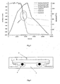
The most recurring problem is that at high temperatures the ceramic specimens adhere to the supporting rods. Since such phenomenon does not occur equally at both ends, the specimen midpoint, because of the material shrinkage, translates horizontally invalidating the experimental test results (figs. 2a and 2b ). As it is shown infig. 3 , the characteristic effect of the above described translation is also graphically visible on the experimental bending curve. The characteristic "peak" caused by the adhesion phenomena is indicated with 1 - The present invention, instead, relates to the development of a numerical-experimental methodology to study the material viscous behavior and to estimate the real viscosity evolution. The following detailed description of the invention refers to an absolutely not limiting example concerning a numerical-experimental procedure and all the devices to measure the viscosity to be applied to all materials that exhibit shrinkage and viscous deformation at the same time.
-
-
Fig. 1 shows the test configuration used in the conventional experimental tests; -
Figs. 2a and 2b show two specimens at the end of the conventional experimental test. The asymmetric translation phenomena, caused by the specimen adhesion to the supporting rods, is highlighted; -
Fig. 3 shows some experimental bending curves obtained performing the conventional test; -
Fig. 4 shows a CAD assembly of the innovative bending test configuration; -
Fig. 5 shows the geometric projections and axonometric view of the supporting structure of the new bending test configuration; -
Fig. 6 shows the geometric projections and axonometric view of the material specimen of the new bending test configuration; -
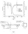
Fig. 7 is an example of experimental analysis results obtained by using the new bending test configuration based on the specimen geometry and supporting structure; -
Fig. 8 shows a schematic representation of the conventional bending test known in literature; -
Fig. 9 shows a comparison between the material sintering rate, measured during a dilatometric test, and the material bending rate measured by means of the new bending test configuration; -
Fig. 10 shows an example of material viscosity curves plotted by varying the parameter h (fig. 8 ); -
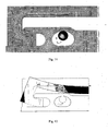
Fig. 11 shows the numerical model and the boundary conditions of the new bending test configuration; -
Fig. 12 shows the results of the new bending test numerical simulation and in particularly the deformed and undeformed configuration of the material specimen; -
Fig. 13 shows the comparison between the experimental test results and the numerical simulation ones of the new bending test (fig. 4 ) for different values of the parameter h (fig. 8 ); -
Fig. 14 shows a comparison between the experimental curve and the numerical one (FEM analysis) corresponding to the h target value: h=h*=h3; -
Fig. 15 shows the real evolution of material viscosity, found by means of the developed numerical-experimental methodology; -
Fig. 16 shows the supporting structure and the deformed material specimen at the end of the developed bending test; -
Fig. 17 shows a flow chart summarizing the developed numerical-experimental methodology to determine the real material viscosity. - The numerical-experimental methodology has been developed to study the viscous behavior of ceramic materials during firing; however, this methodology is applicable as well to study all the materials, that during a process, exhibit shrinkage and viscous deformation at the same time, as for example polymeric materials, composite materials and others.
- Due to the described drawbacks, relating to the adhesion phenomena, the viscosity determined by the conventional experimental test does not correspond to the real material property.
- The present invention aims at overcoming the drawbacks of the conventional experimental test configuration (
fig. 8 ) and at determining the real material viscosity by means of the numerical-experimental methodology, which consists of: - ✔ an innovative bending experimental test configuration able to solve the problems concerning the conventional bending test;
- ✔ a numeric simulation of the developed experimental test to determine the material viscosity as function of temperature. In particular, the numerical analyses allowed to identify an equivalent equation to calculate the material viscosity by using the test results of the new bending test configuration.
- In
fig. 3 the undesired effect of the specimens translation is shown. This effect arises from the bending curve obtained experimentally during the conventional test. As mentioned above, the undesirable adhesion between the supporting rods (4) and the specimen causes a horizontal translation of the specimen midpoint, which invalidates the experimental test (figs. 2a and 2b ). The graphically highlighted "peak" (1) is the experimental evidence of what described. - In order to solve the above characterization problems, encountered in the conventional bending test, a new test configuration has been developed.
Fig. 4 shows the new test configuration developed for the study of the viscous behavior of ceramic materials during firing. The configuration includes the use of a supporting structure (2) on which the C-shaped specimen (3), as can be seen infig. 4 , to be analyzed is placed; the resulting assembly is then installed on the supporting rods (4) of the measuring instrument. - The innovative test configuration, object of the present invention, is shown in
fig 4 ; the supporting rods (4) of the optical instruments are not in direct contact with the specimen (3) to be analyzed, but with a supporting structure (2) provided with two holes (5). Moreover, the supporting structure (2) and the specimen (3) were both designed to prevent the undesired effect of the specimen midpoint translation caused by the combined effect of the material shrinkage and the viscous deformation that invalidates the experimental test. - In fact, in the test configuration the sensor of the optical instrument focuses on the specimen midpoint and during the test it follows its movement measuring the bending as function of time. With the innovative test configuration (
fig. 4 ), the specimen (3), because of the thermal shrinkage, is brought in contact with the fins (9) of the supporting structure (2). This ensures an accurate analysis of the material deformation process and the reliability of experimental test results. -
Figures 5 and 6 respectively show the drawings of the supporting structure (2) and of the specimen (3). The orthogonal projection and the isometric view were reported. The supporting structure (2) consists of a central body, having structural functions, on which were obtained two holes (5). The holes were shaped to allow the installation on the supporting rods (4). At each end it has four fins: the two longest (8) start from the lower base (6) of the structure and allow the placement of the test specimen; the remaining two (9) start from the top of the structure (7) and during the test are always in contact with the material specimen (3) to prevent any horizontal movement. The fins edges are rounded to prevent specimen damage during the deformation process. Finally, at the top of the structure a groove (10) was made to increase the maximum displacement of the material specimen (3) to be measured. - By means of the test configuration described is possible to carry out a bending test by using a dedicated optical instrument that focuses on the specimen midpoint and during the test follows the movement by measuring the bending as function of time. Therefore, some tests were carried out on specimens having the same geometric properties in order to ensure the repeatability of results. In
fig. 7 the results of two experimental tests were reported with the aim of highlighting the repeatability of results and the absence of undesirable events that occur in the conventional test (Fig. 3 ). It follows that the innovative test configuration developed, object of the present invention, has solved the adhesion problem and at the same time has allowed to obtain reliable and repeatable results. - Another element of the ad hoc methodology developed consists of the experimental test numerical simulation to determine the material viscosity as function of temperature. It is known from the literature that, starting from the bending theory of a linear elastic beam subjected to a uniformly distributed load, it is possible to determine the material viscous properties.
- As shown in
Fig. 8 , for a linear elastic solid, the displacement in the midpoint (x = 0), δx=0, is equal to:
where g is the gravity acceleration, p the densification curve, L the span, E the elastic modulus and h the section height. - Considering the analogy between a linear elastic and linear viscous solid, the elastic modulus E and the bending δx-0, in (I), can be respectively replaced by the uniaxial viscosity η and the bending rate of the beam midpoint δ x=0 (S. H. Lee, G. L. Messing, D. J. Green J. Am. Ceram. Soc. 2003); the (I) becomes:

- Finally, a formula has been identified to determine the viscosity of a solid starting from the bending rate δ x=0 by using the conventional bending test. As already stated, analyzing the tests results carried out on ceramic specimens (and however for all the materials that shrink and have a viscous behavior at the same time) the bending curves were not reliable and may not reflect the real behavior of the material due to the undesirable adhesion between the instrument supporting rods (4) and the material specimen. This involves that these experimental tests can't be used to determine the bending rate δ x=0, and, as a consequence, are not suitable to calculate the ceramic material viscosity during firing.
- As described above, this problem has been solved by means of the development of an ad hoc experimental methodology able to provide reliable and repeatable results of the material viscous behavior.
- Starting from the experimental test results, carried out on the C shaped specimen geometry, a study on how to use these data to determine the material viscosity was done. The aim was to derive a formula, in which these experimental data could be used, starting from the relation (II) applicable in a conventional two points bending test. Assuming the ceramic materials as a case study, absolutely not limiting, the viscous flow involves both the material shrinkage (sintering) and the viscous deformation.
-
Fig. 9 shows the similarity between the dilatometric (sintering) and bending rate curves: the two curves have the same characteristic times (and as consequence characteristic temperatures) that determine the material behavior (starting point, maximum peak and end value measured on the abscisses axis). The sintering rate is a material property: its shape and the characteristic times/temperatures are data typical of the material under investigation. On the contrary the shape of the bending rate curve depends on the intrinsic material properties and in particular on the viscosity; whereas, the numeric values measured on the vertical axis depends on the particular specimen geometry and then on the test configuration. Finally, the similarity between the sintering rate and the bending rate is due to the fact that the physical phenomenon that governs the sintering process and viscous flow process is the same. - Afterwards, the viscous flow is responsible for the viscous deformation processes of the ceramic materials and is also the predominant densification mechanism during firing; it follows that the material viscosity governs both the viscous flow process in the bending test and the sintering process in the dilatometric tests.
- On the basis of these considerations can be argued that the bending rate curve , δx =0 (corrected by the measurement errors described above), of the two points bending test configuration, will have a shape similar to the one of the sintering rate. Finally, the curve's shape will be the same as the one obtainable during the bending test on the C shaped specimen geometry as all phenomena are dependent on viscous properties of the material.
- Consequently, in the relation (II) it is possible to use the bending rate, measured during the new bending test, indicated as δ x=0, to calculate the material viscosity (valid in the two points bending test configuration).This can be done if it is possible to define the geometric characteristic (L* and h*) of a beam that in the conventional two points bending test deforms in the same manner of the C shaped specimen geometry in the developed bending test configuration, δ x=0.
- In such a way, the (II) can be rewritten equivalently as follows:
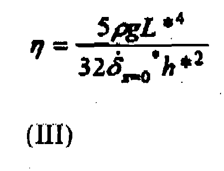
- For simplicity, once fixed L* equal to L (the span of the supporting rods 4), the geometric characteristic to be determined, to assure the equivalence, is h*. The equivalence between the relations (II) and (III) is due to the fact that the viscosity is a material property.
- To identify the value h*, which corresponds to the correct curve of material viscosity, were used FEM codes able to reproduce numerically the bending experimental test of the C shaped specimen geometry. To that end, a sensitivity analysis, considering different values of h, is needed to identify the value h* for which there is a good agreement between the numerical and the experimental curves of the bending test on the C shaped specimen geometry.
- As described by (III), once defined δ x=0 and L *, the viscosity η varies theoretically according to the value of h.
Fig. 10 shows how the material viscosity varies with h; the viscosity curves, calculated by means of the equation (III), were used to perform the numerical simulations in order to determine the real material viscosity.Fig. 11 shows the numerical model used in FEM analysis andfig. 12 illustrates the simulation results in terms of displacements along the y direction , along which the load acts. - The numerical analysis results (deformed configuration) are in good agreement with those obtained by the experimental tests (
Fig. 16 ). - As already stated, the viscosity curve varies with h (
Fig. 10 ) and, as a consequence, the flexural deformation, resulting from FEM analysis, is a function of h (Fig. 13 ). Therefore, analyzing the differences between the experimental test results and those obtained by FEM analysis for different values of h (shown inFig. 13 ), it is possible to calibrate the value of h in order to accurately determine the viscosity of the ceramic material during firing. For the material, proposed in this description, absolutely not limiting, it follows that the bending curve that best approximates the behavior of the ceramic material during firing is the one corresponding to a value of h equal to h3 (Fig. 14 ). Finally it was possible to accurately determine the viscosity of the ceramic material during firing, as shown inFig. 15. Fig. 16 , however, shows the specimen deformed by the experimental procedure, object of the present invention. -
Fig. 17 represents a flow chart in which all the steps concerning both the developed methodology and the numerical-experimental calibration procedure are summarized. With reference to this scheme the main steps of the numerical-experimental method to study the viscous behavior of materials and to accurately determine the viscosity of a material can be summarized as follows: first a significant numbers of material specimens have to be produced. All the specimens (3) must have the same geometry and dimensions of the new experimental test developed (Fig. 4 ); then, starting from the experimental tests results the bending and bending rate curves, respectively

- The experimental bending curve,


- A numerical simulation of the bending experimental test of the C shape geometry is carried out. The numerical bending curve in the specimen midpoint,


- The next step is to check the deviations between numerical and experimental curve. If deviations are equal or less than the threshold value, the value of h defined is the target value h*, for which the relations (II) and (III), are equivalent. Consequently, the viscosity curve obtained is the real material properties. Conversely, if the deviations are greater than the threshold value, the procedure is iteratively repeated (
steps
Claims (2)
- Numerical-experimental methodology to study the viscous behavior of ceramic materials and to determine the material viscosity as a function of temperature, comprising the steps of:(i) producing a significant number of material specimens (3) to be used for a bending experimental tests with an optical instrument;(ii) carrying out the bending experimental test in which the material specimen (3), loaded at least by its own weight, undergoes thermal and viscous deformations and measuring the vertical displacement in the specimen midpoint as a function of temperature;(iii) deriving, starting from said experimental test, a bending curve and a bending rate curve in the specimen midpoint;(iv) repeating the bending experimental test for a significant number of specimens in order to verify the results repeatability;(v) defining an equation to calculate the material viscosity by using the bending rate curve,


where g is the gravity acceleration, p the material densification curve, L* and h* are, respectively, the span and the section height of an equivalent beam that, in the two points bending configuration test, deforms with the same bending rate, (vi) performing FEM numerical analyses of the bending experimental test, which are complementary to the experimental test results, to identify said parameter L* and h* and to determine the correct material viscosity as a function of the temperature,and wherein said methodology is characterized by the fact that;a. said bending experimental test is performed by using a C shaped test specimen (3) that is assembled on a dedicated supporting structure (2), in order to avoid adhesion problems of the conventional bending test, and by installing the assembly of said test specimen (3) and said supporting structure (2), on the measuring instrument, wherein said test specimen (3) is not in contact with the supporting rods (4) of the measuring instrument during the whole test,b. said supporting structure (2) comprises a pair of boles (5), shaped to allow the installation on supporting rods (4) of the measuring instrument, a pair of fins (8) that allow the placement of the test specimen (3) and a pair of fins (9) with rounded edges that during the bending test are always in contact with the test specimen (3) adapted to prevent any horizontal movement of the specimen (3).
 - Device to carry out the numerical-experimental methodology, according to claim 1, comprising a supporting structure (2) on which a C-shaped specimen (3) to be analyzed is placed, characterised in that said supporting structure (2) is provided with at least a pair of fins (8) starting from the lower base (6) on which the Specimen (3) can be placed, a pair of fins (9) starting from the top of the structure (7) adapted to be always in contact with the inside of the c-shaped specimen (3) to prevent horizontal movement of the specimen (3) during a bending test and at least a pair of holes (5) shaped to allow the installation on supporting rods (4).
Priority Applications (1)
| Application Number | Priority Date | Filing Date | Title |
|---|---|---|---|
| EP11425153.1A EP2543985B1 (en) | 2011-07-07 | 2011-07-07 | Numerical-experimental metodology to study the viscous behaviour of materials |
Applications Claiming Priority (1)
| Application Number | Priority Date | Filing Date | Title |
|---|---|---|---|
| EP11425153.1A EP2543985B1 (en) | 2011-07-07 | 2011-07-07 | Numerical-experimental metodology to study the viscous behaviour of materials |
Publications (2)
| Publication Number | Publication Date |
|---|---|
| EP2543985A1 EP2543985A1 (en) | 2013-01-09 |
| EP2543985B1 true EP2543985B1 (en) | 2015-09-16 |
Family
ID=44764261
Family Applications (1)
| Application Number | Title | Priority Date | Filing Date |
|---|---|---|---|
| EP11425153.1A Not-in-force EP2543985B1 (en) | 2011-07-07 | 2011-07-07 | Numerical-experimental metodology to study the viscous behaviour of materials |
Country Status (1)
| Country | Link |
|---|---|
| EP (1) | EP2543985B1 (en) |
Families Citing this family (1)
| Publication number | Priority date | Publication date | Assignee | Title |
|---|---|---|---|---|
| CN106970184B (en) * | 2017-04-28 | 2023-03-14 | 长安大学 | Experimental device for be used for detecting solid material deformation |
Family Cites Families (3)
| Publication number | Priority date | Publication date | Assignee | Title |
|---|---|---|---|---|
| JPS57175939A (en) * | 1981-04-24 | 1982-10-29 | Nippon Kokan Kk <Nkk> | Hot strength measurement in reducing atmosphere |
| FR2639117A1 (en) * | 1988-11-17 | 1990-05-18 | Sercovam Sa | Apparatus for measuring the hot pressing capacity of preimpregnated materials: Flexometer |
| JP2005337834A (en) * | 2004-05-26 | 2005-12-08 | Jfe Steel Kk | Creep test alternative method and creep test alternative test machine |
-
2011
- 2011-07-07 EP EP11425153.1A patent/EP2543985B1/en not_active Not-in-force
Also Published As
| Publication number | Publication date |
|---|---|
| EP2543985A1 (en) | 2013-01-09 |
Similar Documents
| Publication | Publication Date | Title |
|---|---|---|
| KR100948035B1 (en) | Method of obtaining true strain-stress curve for high strain using tensile test and finite element method and tensile tester using the same | |
| CN110501224B (en) | Test and calculation method for measuring true stress-strain curve of material | |
| Miller | Testing and Analysis | |
| CN110702886B (en) | Method for inverting parameters of mass concrete material | |
| CN110728093B (en) | An optimization method for temperature control of mass concrete | |
| US8364425B2 (en) | Method and system for determining properties of an asphalt material | |
| CN111625888B (en) | A calculation method of residual bearing capacity of concrete T-beam considering the effect of fire cracks | |
| CN117954022B (en) | Estimation method of fatigue crack growth rate of metal material under elastoplastic condition | |
| Pham et al. | Hybrid fitting-numerical method for determining strain-hardening behavior of sheet metals | |
| KR20170022094A (en) | Pot Bearing, Manufacturing Method thereof, and Measuring Method of Load using such Pot Bearing | |
| CN120820263B (en) | Steel structure stress monitoring method based on distributed optical fiber sensing | |
| US20080234951A1 (en) | Gravity Flowmeter for Materials Analysis | |
| CN115950766B (en) | A force-displacement correction method for instrumented impact testing | |
| EP2543985A1 (en) | Numerical-experimental metodology to study the viscous behaviour of materials | |
| CN115017603B (en) | A calibration method for hardening curve of automobile metal sheet | |
| CA2790246A1 (en) | Method and system for determining properties of an asphalt material | |
| JP6919742B1 (en) | How to identify the constriction limit strain of a metal plate | |
| Chandran | Fracture mechanics analysis of generalized compact tension specimen geometry using the mechanics of net-section | |
| CN115098973B (en) | A method for obtaining shear constitutive model for characterizing dual damage characteristics of composite materials | |
| CN113777283A (en) | Method for directly measuring concrete stress of dam | |
| KR102182792B1 (en) | Life test method for materials used in artificial tooth | |
| CN112380610A (en) | Method for determining internal force according to actual measurement deformation of building envelope | |
| Cavariani et al. | A full-field calibration approach on material parameter identifaction | |
| CN122062992A (en) | Solving method and system for fatigue crack growth rate baseline of metal material | |
| KR20250082491A (en) | Method for updating analytical properties of specimens |
Legal Events
| Date | Code | Title | Description |
|---|---|---|---|
| PUAI | Public reference made under article 153(3) epc to a published international application that has entered the european phase |
Free format text: ORIGINAL CODE: 0009012 |
|
| AK | Designated contracting states |
Kind code of ref document: A1 Designated state(s): AL AT BE BG CH CY CZ DE DK EE ES FI FR GB GR HR HU IE IS IT LI LT LU LV MC MK MT NL NO PL PT RO RS SE SI SK SM TR |
|
| AX | Request for extension of the european patent |
Extension state: BA ME |
|
| 17P | Request for examination filed |
Effective date: 20130703 |
|
| RBV | Designated contracting states (corrected) |
Designated state(s): AL AT BE BG CH CY CZ DE DK EE ES FI FR GB GR HR HU IE IS IT LI LT LU LV MC MK MT NL NO PL PT RO RS SE SI SK SM TR |
|
| 17Q | First examination report despatched |
Effective date: 20130820 |
|
| GRAP | Despatch of communication of intention to grant a patent |
Free format text: ORIGINAL CODE: EPIDOSNIGR1 |
|
| INTG | Intention to grant announced |
Effective date: 20150410 |
|
| GRAS | Grant fee paid |
Free format text: ORIGINAL CODE: EPIDOSNIGR3 |
|
| GRAA | (expected) grant |
Free format text: ORIGINAL CODE: 0009210 |
|
| AK | Designated contracting states |
Kind code of ref document: B1 Designated state(s): AL AT BE BG CH CY CZ DE DK EE ES FI FR GB GR HR HU IE IS IT LI LT LU LV MC MK MT NL NO PL PT RO RS SE SI SK SM TR |
|
| REG | Reference to a national code |
Ref country code: GB Ref legal event code: FG4D |
|
| REG | Reference to a national code |
Ref country code: CH Ref legal event code: EP |
|
| REG | Reference to a national code |
Ref country code: IE Ref legal event code: FG4D |
|
| REG | Reference to a national code |
Ref country code: AT Ref legal event code: REF Ref document number: 750172 Country of ref document: AT Kind code of ref document: T Effective date: 20151015 |
|
| REG | Reference to a national code |
Ref country code: DE Ref legal event code: R096 Ref document number: 602011019796 Country of ref document: DE |
|
| REG | Reference to a national code |
Ref country code: NL Ref legal event code: MP Effective date: 20150916 |
|
| PG25 | Lapsed in a contracting state [announced via postgrant information from national office to epo] |
Ref country code: LV Free format text: LAPSE BECAUSE OF FAILURE TO SUBMIT A TRANSLATION OF THE DESCRIPTION OR TO PAY THE FEE WITHIN THE PRESCRIBED TIME-LIMIT Effective date: 20150916 Ref country code: GR Free format text: LAPSE BECAUSE OF FAILURE TO SUBMIT A TRANSLATION OF THE DESCRIPTION OR TO PAY THE FEE WITHIN THE PRESCRIBED TIME-LIMIT Effective date: 20151217 Ref country code: NO Free format text: LAPSE BECAUSE OF FAILURE TO SUBMIT A TRANSLATION OF THE DESCRIPTION OR TO PAY THE FEE WITHIN THE PRESCRIBED TIME-LIMIT Effective date: 20151216 Ref country code: LT Free format text: LAPSE BECAUSE OF FAILURE TO SUBMIT A TRANSLATION OF THE DESCRIPTION OR TO PAY THE FEE WITHIN THE PRESCRIBED TIME-LIMIT Effective date: 20150916 Ref country code: FI Free format text: LAPSE BECAUSE OF FAILURE TO SUBMIT A TRANSLATION OF THE DESCRIPTION OR TO PAY THE FEE WITHIN THE PRESCRIBED TIME-LIMIT Effective date: 20150916 |
|
| REG | Reference to a national code |
Ref country code: LT Ref legal event code: MG4D |
|
| REG | Reference to a national code |
Ref country code: AT Ref legal event code: MK05 Ref document number: 750172 Country of ref document: AT Kind code of ref document: T Effective date: 20150916 |
|
| PG25 | Lapsed in a contracting state [announced via postgrant information from national office to epo] |
Ref country code: RS Free format text: LAPSE BECAUSE OF FAILURE TO SUBMIT A TRANSLATION OF THE DESCRIPTION OR TO PAY THE FEE WITHIN THE PRESCRIBED TIME-LIMIT Effective date: 20150916 Ref country code: SE Free format text: LAPSE BECAUSE OF FAILURE TO SUBMIT A TRANSLATION OF THE DESCRIPTION OR TO PAY THE FEE WITHIN THE PRESCRIBED TIME-LIMIT Effective date: 20150916 Ref country code: HR Free format text: LAPSE BECAUSE OF FAILURE TO SUBMIT A TRANSLATION OF THE DESCRIPTION OR TO PAY THE FEE WITHIN THE PRESCRIBED TIME-LIMIT Effective date: 20150916 |
|
| PG25 | Lapsed in a contracting state [announced via postgrant information from national office to epo] |
Ref country code: NL Free format text: LAPSE BECAUSE OF FAILURE TO SUBMIT A TRANSLATION OF THE DESCRIPTION OR TO PAY THE FEE WITHIN THE PRESCRIBED TIME-LIMIT Effective date: 20150916 |
|
| PG25 | Lapsed in a contracting state [announced via postgrant information from national office to epo] |
Ref country code: SK Free format text: LAPSE BECAUSE OF FAILURE TO SUBMIT A TRANSLATION OF THE DESCRIPTION OR TO PAY THE FEE WITHIN THE PRESCRIBED TIME-LIMIT Effective date: 20150916 Ref country code: IT Free format text: LAPSE BECAUSE OF FAILURE TO SUBMIT A TRANSLATION OF THE DESCRIPTION OR TO PAY THE FEE WITHIN THE PRESCRIBED TIME-LIMIT Effective date: 20150916 Ref country code: ES Free format text: LAPSE BECAUSE OF FAILURE TO SUBMIT A TRANSLATION OF THE DESCRIPTION OR TO PAY THE FEE WITHIN THE PRESCRIBED TIME-LIMIT Effective date: 20150916 Ref country code: CZ Free format text: LAPSE BECAUSE OF FAILURE TO SUBMIT A TRANSLATION OF THE DESCRIPTION OR TO PAY THE FEE WITHIN THE PRESCRIBED TIME-LIMIT Effective date: 20150916 Ref country code: EE Free format text: LAPSE BECAUSE OF FAILURE TO SUBMIT A TRANSLATION OF THE DESCRIPTION OR TO PAY THE FEE WITHIN THE PRESCRIBED TIME-LIMIT Effective date: 20150916 Ref country code: IS Free format text: LAPSE BECAUSE OF FAILURE TO SUBMIT A TRANSLATION OF THE DESCRIPTION OR TO PAY THE FEE WITHIN THE PRESCRIBED TIME-LIMIT Effective date: 20160116 |
|
| PG25 | Lapsed in a contracting state [announced via postgrant information from national office to epo] |
Ref country code: PT Free format text: LAPSE BECAUSE OF FAILURE TO SUBMIT A TRANSLATION OF THE DESCRIPTION OR TO PAY THE FEE WITHIN THE PRESCRIBED TIME-LIMIT Effective date: 20160118 Ref country code: RO Free format text: LAPSE BECAUSE OF FAILURE TO SUBMIT A TRANSLATION OF THE DESCRIPTION OR TO PAY THE FEE WITHIN THE PRESCRIBED TIME-LIMIT Effective date: 20150916 Ref country code: PL Free format text: LAPSE BECAUSE OF FAILURE TO SUBMIT A TRANSLATION OF THE DESCRIPTION OR TO PAY THE FEE WITHIN THE PRESCRIBED TIME-LIMIT Effective date: 20150916 Ref country code: AT Free format text: LAPSE BECAUSE OF FAILURE TO SUBMIT A TRANSLATION OF THE DESCRIPTION OR TO PAY THE FEE WITHIN THE PRESCRIBED TIME-LIMIT Effective date: 20150916 |
|
| REG | Reference to a national code |
Ref country code: DE Ref legal event code: R097 Ref document number: 602011019796 Country of ref document: DE |
|
| PLBE | No opposition filed within time limit |
Free format text: ORIGINAL CODE: 0009261 |
|
| STAA | Information on the status of an ep patent application or granted ep patent |
Free format text: STATUS: NO OPPOSITION FILED WITHIN TIME LIMIT |
|
| 26N | No opposition filed |
Effective date: 20160617 |
|
| PG25 | Lapsed in a contracting state [announced via postgrant information from national office to epo] |
Ref country code: DK Free format text: LAPSE BECAUSE OF FAILURE TO SUBMIT A TRANSLATION OF THE DESCRIPTION OR TO PAY THE FEE WITHIN THE PRESCRIBED TIME-LIMIT Effective date: 20150916 |
|
| PG25 | Lapsed in a contracting state [announced via postgrant information from national office to epo] |
Ref country code: SI Free format text: LAPSE BECAUSE OF FAILURE TO SUBMIT A TRANSLATION OF THE DESCRIPTION OR TO PAY THE FEE WITHIN THE PRESCRIBED TIME-LIMIT Effective date: 20150916 |
|
| PG25 | Lapsed in a contracting state [announced via postgrant information from national office to epo] |
Ref country code: BE Free format text: LAPSE BECAUSE OF FAILURE TO SUBMIT A TRANSLATION OF THE DESCRIPTION OR TO PAY THE FEE WITHIN THE PRESCRIBED TIME-LIMIT Effective date: 20150916 |
|
| REG | Reference to a national code |
Ref country code: DE Ref legal event code: R119 Ref document number: 602011019796 Country of ref document: DE |
|
| REG | Reference to a national code |
Ref country code: CH Ref legal event code: PL |
|
| GBPC | Gb: european patent ceased through non-payment of renewal fee |
Effective date: 20160707 |
|
| PG25 | Lapsed in a contracting state [announced via postgrant information from national office to epo] |
Ref country code: MC Free format text: LAPSE BECAUSE OF FAILURE TO SUBMIT A TRANSLATION OF THE DESCRIPTION OR TO PAY THE FEE WITHIN THE PRESCRIBED TIME-LIMIT Effective date: 20150916 |
|
| PG25 | Lapsed in a contracting state [announced via postgrant information from national office to epo] |
Ref country code: CH Free format text: LAPSE BECAUSE OF NON-PAYMENT OF DUE FEES Effective date: 20160731 Ref country code: DE Free format text: LAPSE BECAUSE OF NON-PAYMENT OF DUE FEES Effective date: 20170201 Ref country code: FR Free format text: LAPSE BECAUSE OF NON-PAYMENT OF DUE FEES Effective date: 20160801 Ref country code: LI Free format text: LAPSE BECAUSE OF NON-PAYMENT OF DUE FEES Effective date: 20160731 |
|
| REG | Reference to a national code |
Ref country code: FR Ref legal event code: ST Effective date: 20170331 |
|
| REG | Reference to a national code |
Ref country code: IE Ref legal event code: MM4A |
|
| PG25 | Lapsed in a contracting state [announced via postgrant information from national office to epo] |
Ref country code: GB Free format text: LAPSE BECAUSE OF NON-PAYMENT OF DUE FEES Effective date: 20160707 |
|
| PG25 | Lapsed in a contracting state [announced via postgrant information from national office to epo] |
Ref country code: IE Free format text: LAPSE BECAUSE OF NON-PAYMENT OF DUE FEES Effective date: 20160707 |
|
| PG25 | Lapsed in a contracting state [announced via postgrant information from national office to epo] |
Ref country code: LU Free format text: LAPSE BECAUSE OF NON-PAYMENT OF DUE FEES Effective date: 20160707 |
|
| PG25 | Lapsed in a contracting state [announced via postgrant information from national office to epo] |
Ref country code: CY Free format text: LAPSE BECAUSE OF FAILURE TO SUBMIT A TRANSLATION OF THE DESCRIPTION OR TO PAY THE FEE WITHIN THE PRESCRIBED TIME-LIMIT Effective date: 20150916 Ref country code: HU Free format text: LAPSE BECAUSE OF FAILURE TO SUBMIT A TRANSLATION OF THE DESCRIPTION OR TO PAY THE FEE WITHIN THE PRESCRIBED TIME-LIMIT; INVALID AB INITIO Effective date: 20110707 Ref country code: SM Free format text: LAPSE BECAUSE OF FAILURE TO SUBMIT A TRANSLATION OF THE DESCRIPTION OR TO PAY THE FEE WITHIN THE PRESCRIBED TIME-LIMIT Effective date: 20150916 |
|
| PG25 | Lapsed in a contracting state [announced via postgrant information from national office to epo] |
Ref country code: TR Free format text: LAPSE BECAUSE OF FAILURE TO SUBMIT A TRANSLATION OF THE DESCRIPTION OR TO PAY THE FEE WITHIN THE PRESCRIBED TIME-LIMIT Effective date: 20150916 Ref country code: MK Free format text: LAPSE BECAUSE OF FAILURE TO SUBMIT A TRANSLATION OF THE DESCRIPTION OR TO PAY THE FEE WITHIN THE PRESCRIBED TIME-LIMIT Effective date: 20150916 Ref country code: MT Free format text: LAPSE BECAUSE OF NON-PAYMENT OF DUE FEES Effective date: 20160731 |
|
| PG25 | Lapsed in a contracting state [announced via postgrant information from national office to epo] |
Ref country code: BG Free format text: LAPSE BECAUSE OF FAILURE TO SUBMIT A TRANSLATION OF THE DESCRIPTION OR TO PAY THE FEE WITHIN THE PRESCRIBED TIME-LIMIT Effective date: 20150916 |
|
| PG25 | Lapsed in a contracting state [announced via postgrant information from national office to epo] |
Ref country code: AL Free format text: LAPSE BECAUSE OF FAILURE TO SUBMIT A TRANSLATION OF THE DESCRIPTION OR TO PAY THE FEE WITHIN THE PRESCRIBED TIME-LIMIT Effective date: 20150916 |