EP2543874A1 - A wind turbine blade - Google Patents
A wind turbine blade Download PDFInfo
- Publication number
- EP2543874A1 EP2543874A1 EP11172805A EP11172805A EP2543874A1 EP 2543874 A1 EP2543874 A1 EP 2543874A1 EP 11172805 A EP11172805 A EP 11172805A EP 11172805 A EP11172805 A EP 11172805A EP 2543874 A1 EP2543874 A1 EP 2543874A1
- Authority
- EP
- European Patent Office
- Prior art keywords
- wind turbine
- turbine blade
- fibre
- carbon fibres
- blade according
- Prior art date
- Legal status (The legal status is an assumption and is not a legal conclusion. Google has not performed a legal analysis and makes no representation as to the accuracy of the status listed.)
- Withdrawn
Links
- OKTJSMMVPCPJKN-UHFFFAOYSA-N Carbon Chemical compound [C] OKTJSMMVPCPJKN-UHFFFAOYSA-N 0.000 claims abstract description 40
- 229910052799 carbon Inorganic materials 0.000 claims abstract description 40
- 239000000835 fiber Substances 0.000 claims abstract description 28
- 239000000463 material Substances 0.000 claims abstract description 23
- 238000003763 carbonization Methods 0.000 claims abstract description 21
- 229920000642 polymer Polymers 0.000 claims abstract description 17
- 230000002787 reinforcement Effects 0.000 claims abstract description 15
- 229920002430 Fibre-reinforced plastic Polymers 0.000 claims abstract description 13
- 239000011151 fibre-reinforced plastic Substances 0.000 claims abstract description 13
- 239000002243 precursor Substances 0.000 claims abstract description 10
- 239000011159 matrix material Substances 0.000 claims abstract description 9
- 239000000203 mixture Substances 0.000 claims description 9
- 229920002239 polyacrylonitrile Polymers 0.000 claims description 4
- 238000000034 method Methods 0.000 description 8
- 238000004519 manufacturing process Methods 0.000 description 6
- 239000004020 conductor Substances 0.000 description 5
- 239000011248 coating agent Substances 0.000 description 4
- 238000000576 coating method Methods 0.000 description 4
- 239000003365 glass fiber Substances 0.000 description 4
- 238000009826 distribution Methods 0.000 description 3
- 238000004381 surface treatment Methods 0.000 description 3
- 208000025274 Lightning injury Diseases 0.000 description 2
- 239000011152 fibreglass Substances 0.000 description 2
- 239000007788 liquid Substances 0.000 description 2
- RYGMFSIKBFXOCR-UHFFFAOYSA-N Copper Chemical compound [Cu] RYGMFSIKBFXOCR-UHFFFAOYSA-N 0.000 description 1
- 241000196324 Embryophyta Species 0.000 description 1
- 239000004593 Epoxy Substances 0.000 description 1
- 240000007182 Ochroma pyramidale Species 0.000 description 1
- 238000005452 bending Methods 0.000 description 1
- 230000009172 bursting Effects 0.000 description 1
- 125000004432 carbon atom Chemical group C* 0.000 description 1
- 229910052802 copper Inorganic materials 0.000 description 1
- 239000010949 copper Substances 0.000 description 1
- 239000011162 core material Substances 0.000 description 1
- 238000005520 cutting process Methods 0.000 description 1
- 238000001035 drying Methods 0.000 description 1
- 230000000694 effects Effects 0.000 description 1
- 238000007380 fibre production Methods 0.000 description 1
- 238000010348 incorporation Methods 0.000 description 1
- 238000001802 infusion Methods 0.000 description 1
- 238000003780 insertion Methods 0.000 description 1
- 230000037431 insertion Effects 0.000 description 1
- 230000003647 oxidation Effects 0.000 description 1
- 238000007254 oxidation reaction Methods 0.000 description 1
- 238000012856 packing Methods 0.000 description 1
- 229920000728 polyester Polymers 0.000 description 1
- 230000003014 reinforcing effect Effects 0.000 description 1
- 229920005989 resin Polymers 0.000 description 1
- 239000011347 resin Substances 0.000 description 1
- 238000009745 resin transfer moulding Methods 0.000 description 1
- 229920001169 thermoplastic Polymers 0.000 description 1
- 229920001187 thermosetting polymer Polymers 0.000 description 1
- 239000004416 thermosoftening plastic Substances 0.000 description 1
- 239000010409 thin film Substances 0.000 description 1
- 238000012546 transfer Methods 0.000 description 1
- 230000007704 transition Effects 0.000 description 1
- 238000009755 vacuum infusion Methods 0.000 description 1
- 238000005406 washing Methods 0.000 description 1
- 238000004804 winding Methods 0.000 description 1
Images

Classifications
-
- D—TEXTILES; PAPER
- D01—NATURAL OR MAN-MADE THREADS OR FIBRES; SPINNING
- D01F—CHEMICAL FEATURES IN THE MANUFACTURE OF ARTIFICIAL FILAMENTS, THREADS, FIBRES, BRISTLES OR RIBBONS; APPARATUS SPECIALLY ADAPTED FOR THE MANUFACTURE OF CARBON FILAMENTS
- D01F9/00—Artificial filaments or the like of other substances; Manufacture thereof; Apparatus specially adapted for the manufacture of carbon filaments
- D01F9/08—Artificial filaments or the like of other substances; Manufacture thereof; Apparatus specially adapted for the manufacture of carbon filaments of inorganic material
- D01F9/12—Carbon filaments; Apparatus specially adapted for the manufacture thereof
- D01F9/14—Carbon filaments; Apparatus specially adapted for the manufacture thereof by decomposition of organic filaments
-
- F—MECHANICAL ENGINEERING; LIGHTING; HEATING; WEAPONS; BLASTING
- F03—MACHINES OR ENGINES FOR LIQUIDS; WIND, SPRING, OR WEIGHT MOTORS; PRODUCING MECHANICAL POWER OR A REACTIVE PROPULSIVE THRUST, NOT OTHERWISE PROVIDED FOR
- F03D—WIND MOTORS
- F03D1/00—Wind motors with rotation axis substantially parallel to the air flow entering the rotor
- F03D1/06—Rotors
- F03D1/065—Rotors characterised by their construction elements
- F03D1/0675—Rotors characterised by their construction elements of the blades
-
- D—TEXTILES; PAPER
- D01—NATURAL OR MAN-MADE THREADS OR FIBRES; SPINNING
- D01F—CHEMICAL FEATURES IN THE MANUFACTURE OF ARTIFICIAL FILAMENTS, THREADS, FIBRES, BRISTLES OR RIBBONS; APPARATUS SPECIALLY ADAPTED FOR THE MANUFACTURE OF CARBON FILAMENTS
- D01F9/00—Artificial filaments or the like of other substances; Manufacture thereof; Apparatus specially adapted for the manufacture of carbon filaments
- D01F9/08—Artificial filaments or the like of other substances; Manufacture thereof; Apparatus specially adapted for the manufacture of carbon filaments of inorganic material
- D01F9/12—Carbon filaments; Apparatus specially adapted for the manufacture thereof
- D01F9/14—Carbon filaments; Apparatus specially adapted for the manufacture thereof by decomposition of organic filaments
- D01F9/20—Carbon filaments; Apparatus specially adapted for the manufacture thereof by decomposition of organic filaments from polyaddition, polycondensation or polymerisation products
- D01F9/21—Carbon filaments; Apparatus specially adapted for the manufacture thereof by decomposition of organic filaments from polyaddition, polycondensation or polymerisation products from macromolecular compounds obtained by reactions only involving carbon-to-carbon unsaturated bonds
- D01F9/22—Carbon filaments; Apparatus specially adapted for the manufacture thereof by decomposition of organic filaments from polyaddition, polycondensation or polymerisation products from macromolecular compounds obtained by reactions only involving carbon-to-carbon unsaturated bonds from polyacrylonitriles
-
- F—MECHANICAL ENGINEERING; LIGHTING; HEATING; WEAPONS; BLASTING
- F03—MACHINES OR ENGINES FOR LIQUIDS; WIND, SPRING, OR WEIGHT MOTORS; PRODUCING MECHANICAL POWER OR A REACTIVE PROPULSIVE THRUST, NOT OTHERWISE PROVIDED FOR
- F03D—WIND MOTORS
- F03D1/00—Wind motors with rotation axis substantially parallel to the air flow entering the rotor
- F03D1/06—Rotors
- F03D1/065—Rotors characterised by their construction elements
-
- F—MECHANICAL ENGINEERING; LIGHTING; HEATING; WEAPONS; BLASTING
- F03—MACHINES OR ENGINES FOR LIQUIDS; WIND, SPRING, OR WEIGHT MOTORS; PRODUCING MECHANICAL POWER OR A REACTIVE PROPULSIVE THRUST, NOT OTHERWISE PROVIDED FOR
- F03D—WIND MOTORS
- F03D80/00—Details, components or accessories not provided for in groups F03D1/00 - F03D17/00
- F03D80/30—Lightning protection
-
- B—PERFORMING OPERATIONS; TRANSPORTING
- B29—WORKING OF PLASTICS; WORKING OF SUBSTANCES IN A PLASTIC STATE IN GENERAL
- B29L—INDEXING SCHEME ASSOCIATED WITH SUBCLASS B29C, RELATING TO PARTICULAR ARTICLES
- B29L2031/00—Other particular articles
- B29L2031/08—Blades for rotors, stators, fans, turbines or the like, e.g. screw propellers
- B29L2031/082—Blades, e.g. for helicopters
-
- F—MECHANICAL ENGINEERING; LIGHTING; HEATING; WEAPONS; BLASTING
- F05—INDEXING SCHEMES RELATING TO ENGINES OR PUMPS IN VARIOUS SUBCLASSES OF CLASSES F01-F04
- F05B—INDEXING SCHEME RELATING TO WIND, SPRING, WEIGHT, INERTIA OR LIKE MOTORS, TO MACHINES OR ENGINES FOR LIQUIDS COVERED BY SUBCLASSES F03B, F03D AND F03G
- F05B2280/00—Materials; Properties thereof
- F05B2280/20—Inorganic materials, e.g. non-metallic materials
- F05B2280/2006—Carbon, e.g. graphite
-
- F—MECHANICAL ENGINEERING; LIGHTING; HEATING; WEAPONS; BLASTING
- F05—INDEXING SCHEMES RELATING TO ENGINES OR PUMPS IN VARIOUS SUBCLASSES OF CLASSES F01-F04
- F05B—INDEXING SCHEME RELATING TO WIND, SPRING, WEIGHT, INERTIA OR LIKE MOTORS, TO MACHINES OR ENGINES FOR LIQUIDS COVERED BY SUBCLASSES F03B, F03D AND F03G
- F05B2280/00—Materials; Properties thereof
- F05B2280/50—Intrinsic material properties or characteristics
-
- F—MECHANICAL ENGINEERING; LIGHTING; HEATING; WEAPONS; BLASTING
- F05—INDEXING SCHEMES RELATING TO ENGINES OR PUMPS IN VARIOUS SUBCLASSES OF CLASSES F01-F04
- F05B—INDEXING SCHEME RELATING TO WIND, SPRING, WEIGHT, INERTIA OR LIKE MOTORS, TO MACHINES OR ENGINES FOR LIQUIDS COVERED BY SUBCLASSES F03B, F03D AND F03G
- F05B2280/00—Materials; Properties thereof
- F05B2280/60—Properties or characteristics given to material by treatment or manufacturing
- F05B2280/6003—Composites; e.g. fibre-reinforced
-
- Y—GENERAL TAGGING OF NEW TECHNOLOGICAL DEVELOPMENTS; GENERAL TAGGING OF CROSS-SECTIONAL TECHNOLOGIES SPANNING OVER SEVERAL SECTIONS OF THE IPC; TECHNICAL SUBJECTS COVERED BY FORMER USPC CROSS-REFERENCE ART COLLECTIONS [XRACs] AND DIGESTS
- Y02—TECHNOLOGIES OR APPLICATIONS FOR MITIGATION OR ADAPTATION AGAINST CLIMATE CHANGE
- Y02E—REDUCTION OF GREENHOUSE GAS [GHG] EMISSIONS, RELATED TO ENERGY GENERATION, TRANSMISSION OR DISTRIBUTION
- Y02E10/00—Energy generation through renewable energy sources
- Y02E10/70—Wind energy
- Y02E10/72—Wind turbines with rotation axis in wind direction
Definitions
- the longitudinally extending load carrying structure is a main laminate forming part of a shelf structure.
- the longitudinally extending load carrying structure is an inner beam or spar box connecting outer shell structures.
- the fibre reinforcement material is constituted by carbon fibres.
- the first and second oblong shell parts 3, 4 comprise a fibre-reinforced polymer material produced by means of an infusion process, such as vacuum infusion or VARTM (Vacuum Assisted Resin Transfer Moulding).
- an infusion process such as vacuum infusion or VARTM (Vacuum Assisted Resin Transfer Moulding).
- liquid polymer also called resin
- the polymer can be thermoset plastic or thermoplastics.
- the carbonisation process leaves a fibre composed of long, tightly interlocked chains of carbon atoms.
- the carbonisation temperature influences the grade of carbon fibre and modulus of elasticity which, for instance, may be from 200 to more than 600 GPa.
- the carbon fibres employed may have been produced in a carbonisation process that has been modified to reduce the carbonisation degree of the carbon fibres. For instance, the carbonisation temperature may be reduced to below 1000 °C.
- the stretching process may be speeded up.
- a coating or surface treatment may be provided on the carbon fibre surface.
- R s is then considered the sheet resistance.
Landscapes
- Engineering & Computer Science (AREA)
- Chemical & Material Sciences (AREA)
- Mechanical Engineering (AREA)
- Sustainable Energy (AREA)
- Sustainable Development (AREA)
- Combustion & Propulsion (AREA)
- Life Sciences & Earth Sciences (AREA)
- General Engineering & Computer Science (AREA)
- Chemical Kinetics & Catalysis (AREA)
- General Chemical & Material Sciences (AREA)
- Textile Engineering (AREA)
- Wind Motors (AREA)
- Turbine Rotor Nozzle Sealing (AREA)
- Reinforced Plastic Materials (AREA)
Abstract
The wind turbine blade (1) includes a structure made of a fibre reinforced polymer material including a polymer matrix and fibre reinforcement material embedded in the polymer matrix. The fibre reinforcement material includes carbon fibres that have been produced by carbonisation of a precursor to a carbonisation degree of 60.% to 80%.
Description
- The present invention relates to a wind turbine blade including a structure made of a fibre reinforced polymer material including a polymer matrix and fibre reinforcement material embedded in the polymer matrix, wherein the fibre reinforcement material includes carbon fibres.
- The damages to the wind turbine blades caused by strokes of lightning can be rather comprehensive. Extremely strong currents of the
magnitude 10 to 200 kA are involved within a very short period. The power involved is low, but the effect is very strong and can cause burstings because the air confined in the blade expands explosively. It is known to insert strong interlaced cables in the blade so as to divert the lightning. Then a particular receptor is provided at the tip of the blade, said receptor serving to capture the lightning as well as to prevent this location from being too strongly heated. Furthermore it is known to reinforce each blade by means of a carbon fibre coating. A copper web can optionally be applied onto the carbon fibre coating so as to protect said coating. -
WO 00/14405 -
EP 1 664 528 B1 describes a method of lightning-proofing a wind turbine blade on a wind-energy plant The blade comprises a blade, shell configured essentially as a fibre-reinforced laminate, which laminate comprises electrically conductive fibres, wherein the blade comprises at least one lightning arrester configured for conducting lightning current, including preferably to ground. The method comprises that the electrically conductive fibres are connected to each other, and that at least one metallic receptor is arranged for capturing lightning current at or in proximity of the external face of the blade; and that the receptor and the fibres are connected to the lightning arrester for equalising the difference in potential between the lightning arrester and the electrically conductive fibres. When the electrically conductive fibres are connected to each other, the fibres will cooperate on the conduction of a possible lightning current to prevent the current from running in individual fibres. Simultaneously the metallic receptor will serve as the primary lightning capturing device and reduce the risk of lightning striking the laminate. The receptor being connected to the lightning arrester, the current will predominately be conducted to ground, while the risk of transfer to the laminate is minimised in that a possible difference in potential between fibres and lightning arrester has been equalised. -
WO 03/078833 -
WO 03/078832 - It is thus seen that known wind turbine blades incorporating carbon fibres in order to improve properties such as weight and strength are generally complicated to manufacture due to the necessary precautions in order to prevent damages caused by lightning strokes.
- On the other hand, with an increasing blade length to even more than 100 metres, it may be necessary to reduce the relative weight of the blades. Furthermore, stiffer blades with better fatigue performance may be required.
- The object of the present invention is to provide a wind turbine blade having improved properties with regard to weight and strength and at the same time being simpler to manufacture.
- In view of this object, the carbon fibres have been produced by carbonisation of a precursor to a carbonisation degree of 60% to 80%.
- Thereby, generally a vastly increased resistivity of the fibre reinforced polymer material may be obtained, whereby the need for complicated lightning protection measures may be reduced, as the carbon fibres themselves, substantially, do not conduct the current and therefore will not get damaged, At the same time, a stronger blade may be obtained, as the stiffness of carbon fibres may be up to at least three times higher compared to the stiffness of glass fibres. Furthermore, a better fatigue performance may be obtained by means of carbon fibres than by means of glass fibres. Furthermore, less material may be required per blade. Lower blade mass may lead to the reduction of root bending moment, and blades may even be easier to handle in production, shipping and mounting,
- In an embodiment, the carbon fibres have been produced by carbonisation of a precursor to a carbonisation degree of less than 78%, preferably less than 76%, more preferred less than 74%, even more preferred less than 72%, even more preferred less than 70%, even more preferred less than 68%, even more preferred less than 66%, and most preferred less than 64%.
- In an embodiment, the wind turbine blade includes a longitudinally extending load carrying structure including at least a part of said carbon fibres and preferably all of said carbon fibres.
- In an embodiment, the longitudinally extending load carrying structure is a main laminate forming part of a shelf structure.
- In an embodiment, the longitudinally extending load carrying structure is an inner beam or spar box connecting outer shell structures.
- In an embodiment, the precursor is polyacrylonitrile.
- In an embodiment, the fibre reinforcement material is constituted by carbon fibres.
- In an embodiment, any rectangular sample corresponding in composition and thickness to a part of the shell structure has a sheet resistance of more than 109 ohms-per-square and preferably more than 1010 ohms-per-square.
- In an embodiment, any rectangular sample corresponding in composition and thickness to a part of the longitudinally extending load carrying structure has a sheet resistance of more than 109 ohms-per-square and preferably more than 1010 ohms-per-square.
- The invention will now be explained in more detail below by means of examples of embodiments with reference to the very schematic drawing, in which
-
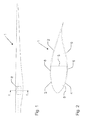
Fig. 1 is a top view of a wind turbine blade; -
Fig. 2 is a cross-section along the line II∼II ofFig.1 ; and -
Fig. 3 is a rectangular sample corresponding in composition and thickness to a part of the shell structure of the wind turbine blade inFigs. 1 and 2 . -
Fig. 1 shows a wind turbine blade 1 according to the invention. The wind turbine blade 1 includes ashell structure 2 made of a fibre reinforced polymer material including a polymer matrix and fibre reinforcement material embedded in the polymer matrix. As it is seen in the figure, theshell structure 2 is composed of two oblong shelf parts, anupper shell part 3 and a lower shelf part 4. Theshelf parts 3, 4. are bonded together at their edges. Furthermore, the shell parts are connected internally by means of longitudinally extending reinforcement elements 5, such as beams or webs, which are aligned within the shell parts of the wind turbine blade 1 and bonded to theshell parts 3, 4. - In the shown embodiment, these reinforcement elements 5 do not carry a substantial part of the load on the blade; they rather serve to connect the shell parts of the wind turbine blade 1.
- The first and second
oblong shell parts 3, 4 comprise a fibre-reinforced polymer material produced by means of an infusion process, such as vacuum infusion or VARTM (Vacuum Assisted Resin Transfer Moulding). During the manufacturing process, liquid polymer, also called resin, is filled into a mould cavity, in which fibre material priorly has been inserted, and where a vacuum is generated in the mould cavity hereby drawing in the polymer. The polymer can be thermoset plastic or thermoplastics. Typically, uniformly distributed fibres are layered in a first rigid mould part, the fibres being rovings, lye, bundles of fibre bands, bands of rovings or mats, which are either felt mats made of individual fibres or woven mats made of fibre rovings. A second mould part, which is often made of a resilient vacuum bag, is subsequently placed on top of the fibre material and sealed against the first mould part in order to generate a mould cavity. By generating a vacuum, typically 80 to 95% of the total vacuum, in the mould cavity between the first mould part and the vacuum bag, the liquid polymer can be drawn in and fill the mould cavity with the fibre material contained herein, So-called distribution layers or distribution tubes, also called inlet channels, are used between the vacuum bag and the fibre material in order to obtain as sound and efficient a distribution of polymer as possible. In most cases the polymer applied is polyester or epoxy, and the fibre reinforcement is according to the present invention based at least partially on carbon fibres, but may also include glass fibres. - According to the present invention, the carbon fibres have been produced by carbonisation of a precursor to a carbonisation degree of 60% to 80%,
- The carbon fibres may have been produced by carbonisation of a precursor to a carbonisation degree of less than 78%, preferably less than 76%, more preferred less than 74%, even more preferred less than 72%, even more preferred less than 70%, even more preferred less than 68%, even more preferred less than 66%, and most preferred less than 64%,
- The precursor may be polyacrylonitrile, Furthermore, the fibre reinforcement material throughout the wind turbine blade may be entirely constituted by carbon fibres.
- The conventional carbon fibre production process may be as follows:
- PAN production process: polymerisation, washing, surface treatment, drying, stretching and packing
- Carbonisation process: stretching, oxidation, carbonisation, surface treatment and winding
- The carbonisation process leaves a fibre composed of long, tightly interlocked chains of carbon atoms. The carbonisation temperature influences the grade of carbon fibre and modulus of elasticity which, for instance, may be from 200 to more than 600 GPa. According to the invention, the carbon fibres employed may have been produced in a carbonisation process that has been modified to reduce the carbonisation degree of the carbon fibres. For instance, the carbonisation temperature may be reduced to below 1000 °C. The stretching process may be speeded up. A coating or surface treatment may be provided on the carbon fibre surface.
- Furthermore, in the embodiment shown, the wind turbine blade includes a longitudinally extending load carrying structure in the form of a
main laminate 6 forming part of the shell structure. The longitudinally extending load carrying structure may include at least a part of said carbon fibres. Such a load carrying structure in the form of a main laminate or the like is typically formed as a fibre insertion which comprises a plurality of fibre reinforcement layers, e.g. between 20 and 50 layers. On each side of the load carrying structure, the blade typically comprises a sandwich structure with a core material, such as balsa wood or foamed polymer, and with an inner and outer skin made of fibre reinforced polymer. - According to another not shown embodiment, the wind turbine blade includes a longitudinally extending load carrying structure in the form of an inner beam or spar box connecting outer shell structures. Said inner beam or spar box may be a separate part bonded to the outer shelf structures and may be adapted to carry a substantial part of the load on the blade. According to this embodiment, a main laminate may not be necessary.
- Sheet resistance is normally applicable to two-dimensional systems where a thin film is considered to be a two-dimensional entity and corresponds to resistivity as employed in three-dimensional systems. When the term sheet resistance is employed, the current flows along the plane of the sheet and not perpendicular to it. In this description, however, sheet resistance is employed to describe the resistivity of a
rectangular sample 7 as shown inFig. 3 corresponding in composition and thickness to a part of the shell structure of a wind turbine blade. Therectangular sample 7 may correspond to arectangular piece 8 cut out of theshell structure 2 as indicated inFig. 1 , InFig. 2 ,broken lines 9 indicate the longitudinal cutting lines along which therectangular piece 8 may be cut out of theshell structure 2. - In a regular three-dimensional conductor, the resistance can be whiten as

where p is the resistivity, A is the cross-sectional area and L is the length. The cross-sectional area can be split into the width W and the sheet thickness t. - By grouping the resistivity with the thickness, the resistance can then be written as:

- Rs is then considered the sheet resistance.
- As the resistance is multiplied by a dimensionless quantity to get the sheet resistance, the units of sheet resistance are ohms or commonly "ohms per square".
- According to an embodiment of the present invention, any rectangular sample corresponding in composition and thickness to a part of the shell structure of the wind turbine blade has a sheet resistance of more than 109 ohms-per-square and preferably more than 1010 ohms-per-square. This means that if a square-formed sample is prepared that corresponds in composition and thickness to a part of the shell structure of the wind turbine blade, this square-formed sample will have a resistance measured between two opposed edges of more than 109 ohms and preferably more than 1010 ohms. Of course, according to this embodiment, the same will be true for any square-formed piece cut out of the shelf structure, through the entire thickness of the shell structure, of the wind turbine blade. If the sample is rectangular with for instance a length L of 2 metres and a width W of 1 metre, the resistance measured between the two opposed end edges (smaller edges) will, according to this embodiment, be of more than 2 x 10⁹ ohms and preferably more than 2 x 10¹⁰ ohms.
- In an embodiment, any rectangular sample corresponding in composition and thickness to a part of the longitudinally extending load carrying structure has a sheet resistance of more than 109 ohms-per-square and preferably more than 1010 ohms-per-square.
- According to the invention, by the incorporation of carbon fibres as reinforcement, an improved wind turbine blade in terms of weight and strength may be obtained without the need for complicated and expensive precautions, such as difficult internal cabling, in order to prevent damages caused by lightning strokes.
Claims (9)
- A wind turbine blade (1) including a structure made of a fibre reinforced polymer material including a polymer matrix and fibre reinforcement material embedded in the polymer matrix, wherein the fibre reinforcement material includes carbon fibres, characterized in that the carbon fibres have been produced by carbonisation of a precursor to a carbonisation degree of 60% to 80%,
- A wind turbine blade according to claim 1, wherein the carbon fibres have been produced by carbonisation of a precursor to a carbonisation degree of less than 78%, preferably less than 76%, more preferred less than 74%, even more preferred less than 72%, even more preferred less than 70%, even more preferred less than 68%, even more preferred less than 66%, and most preferred less than 64%.
- A wind turbine blade according to claim 1 or 2, wherein the wind turbine blade includes a longitudinally extending load carrying structure including at least a part of said carbon fibres and preferably all of said carbon fibres.
- A wind turbine blade according to claim 3, wherein the longitudinally extending load carrying structure is a main laminate (6) forming part of a shell structure (2).
- A wind turbine blade according to claim 3, wherein the longitudinally extending load carrying structure is an inner beam or spar box connecting outer shell structures.
- A wind turbine blade according to any one of the preceding claims, wherein the precursor is polyacrylonitrile.
- A wind turbine blade according to any one of the preceding claims, wherein the fibre reinforcement material is constituted by carbon fibres.
- A wind turbine blade according to any one of the preceding claims, wherein any rectangular sample (7) corresponding in composition and thickness to a part of the shell structure (2) has a sheet resistance of more than 109 ohms-per-square and preferably more than 1010 ohms-per-square,
- A wind turbine blade according to any one of the claims 3 to 7, wherein any rectangular sample (7) corresponding in composition and thickness to a part of the longitudinally extending load carrying structure has a sheet resistance of more than 109 ohms-per-square and preferably more than 1010 ohms-per-square.
Priority Applications (9)
| Application Number | Priority Date | Filing Date | Title |
|---|---|---|---|
| EP11172805A EP2543874A1 (en) | 2011-07-06 | 2011-07-06 | A wind turbine blade |
| ES12733118T ES2712630T3 (en) | 2011-07-06 | 2012-07-06 | Wind turbine blade |
| TR2019/02192T TR201902192T4 (en) | 2011-07-06 | 2012-07-06 | A wind turbine blade. |
| CN201280033577.1A CN103797243B (en) | 2011-07-06 | 2012-07-06 | A wind turbine blade |
| DK12733118.9T DK2729697T3 (en) | 2011-07-06 | 2012-07-06 | A wind turbine blade |
| US14/130,788 US20140241896A1 (en) | 2011-07-06 | 2012-07-06 | A wind turbine blade |
| PCT/EP2012/063206 WO2013004805A1 (en) | 2011-07-06 | 2012-07-06 | A wind turbine blade |
| EP12733118.9A EP2729697B1 (en) | 2011-07-06 | 2012-07-06 | A wind turbine blade |
| PL12733118T PL2729697T3 (en) | 2011-07-06 | 2012-07-06 | A wind turbine blade |
Applications Claiming Priority (1)
| Application Number | Priority Date | Filing Date | Title |
|---|---|---|---|
| EP11172805A EP2543874A1 (en) | 2011-07-06 | 2011-07-06 | A wind turbine blade |
Publications (1)
| Publication Number | Publication Date |
|---|---|
| EP2543874A1 true EP2543874A1 (en) | 2013-01-09 |
Family
ID=46466539
Family Applications (2)
| Application Number | Title | Priority Date | Filing Date |
|---|---|---|---|
| EP11172805A Withdrawn EP2543874A1 (en) | 2011-07-06 | 2011-07-06 | A wind turbine blade |
| EP12733118.9A Active EP2729697B1 (en) | 2011-07-06 | 2012-07-06 | A wind turbine blade |
Family Applications After (1)
| Application Number | Title | Priority Date | Filing Date |
|---|---|---|---|
| EP12733118.9A Active EP2729697B1 (en) | 2011-07-06 | 2012-07-06 | A wind turbine blade |
Country Status (8)
| Country | Link |
|---|---|
| US (1) | US20140241896A1 (en) |
| EP (2) | EP2543874A1 (en) |
| CN (1) | CN103797243B (en) |
| DK (1) | DK2729697T3 (en) |
| ES (1) | ES2712630T3 (en) |
| PL (1) | PL2729697T3 (en) |
| TR (1) | TR201902192T4 (en) |
| WO (1) | WO2013004805A1 (en) |
Cited By (1)
| Publication number | Priority date | Publication date | Assignee | Title |
|---|---|---|---|---|
| EP2784106A1 (en) * | 2013-03-28 | 2014-10-01 | Siemens Aktiengesellschaft | Composite structure |
Families Citing this family (7)
| Publication number | Priority date | Publication date | Assignee | Title |
|---|---|---|---|---|
| MA44103A (en) * | 2015-12-23 | 2021-04-21 | Lm Wp Patent Holding As | WIND TURBINE BLADES AND ASSOCIATED MANUFACTURING PROCESSES |
| US10648456B2 (en) | 2016-10-21 | 2020-05-12 | General Electric Company | Organic conductive elements for deicing and lightning protection of a wind turbine rotor blade |
| CN110198576A (en) * | 2018-02-27 | 2019-09-03 | 吴金珠 | Electrothermal chip structure, installation method, forming method and wind power generating set |
| CN108998964A (en) * | 2018-08-10 | 2018-12-14 | 佛山腾鲤新能源科技有限公司 | A kind of preparation method of the anti-freeze wind electricity blade material of noise reduction |
| US10830207B2 (en) * | 2018-08-28 | 2020-11-10 | General Electric Company | Spar configuration for jointed wind turbine rotor blades |
| US20220042494A1 (en) * | 2020-08-10 | 2022-02-10 | Ut-Battelle, Llc | Low-cost carbon fiber-based lightning strike protection |
| WO2024012642A1 (en) * | 2022-07-11 | 2024-01-18 | Vestas Wind Systems A/S | A wind turbine blade spar cap and a method for manufacturing a wind turbine blade spar cap |
Citations (7)
| Publication number | Priority date | Publication date | Assignee | Title |
|---|---|---|---|---|
| EP0278139A1 (en) * | 1984-10-12 | 1988-08-17 | Zoltek Corporation | Manufacture of controlled surface resistance carbon fibre sheet products |
| US4816242A (en) * | 1985-10-11 | 1989-03-28 | Basf Aktiengesellschaft | Production of partially carbonized polymeric fibrous material having an electrical resistivity of enhanced stability |
| WO2000014405A1 (en) | 1998-09-09 | 2000-03-16 | Lm Glasfiber A/S | Lightning protection for wind turbine blade |
| US20010024722A1 (en) * | 1996-05-24 | 2001-09-27 | Toray Industries, Inc. | Carbon fibers, acrylic fibers and process for producing the acrylic fibers |
| WO2003078832A1 (en) | 2002-03-19 | 2003-09-25 | Lm Glasfiber A/S | Transition zone in wind turbine blade |
| WO2003078833A1 (en) | 2002-03-19 | 2003-09-25 | Lm Glasfiber A/S | Wind turbine blade with carbon fibre tip |
| EP1664528B1 (en) | 2003-09-15 | 2010-12-29 | Lm Glasfiber A/S | A method of lightning-proofing a blade for a wind-energy plant |
Family Cites Families (9)
| Publication number | Priority date | Publication date | Assignee | Title |
|---|---|---|---|---|
| US5820788A (en) * | 1997-01-29 | 1998-10-13 | Sgl Technic Ltd. | Electroconductive antistatic polymers containing carbonaceous fibers |
| US6399199B1 (en) * | 1999-12-28 | 2002-06-04 | Toray Industries Inc. | Prepeg and carbon fiber reinforced composite materials |
| US7120004B2 (en) * | 2003-08-18 | 2006-10-10 | Hall Allen L | Current diverter strip and methods |
| CN101855396B (en) * | 2007-11-09 | 2012-07-18 | 维斯塔斯风力系统有限公司 | A structural mat for reinforcing a wind turbine blade structure, a wind turbine blade and a method for manufacturing a wind turbine blade |
| US8986487B2 (en) * | 2008-04-30 | 2015-03-24 | Vestas Wind Systems A/S | Consolidated composite pre-form |
| US9174396B2 (en) * | 2008-07-14 | 2015-11-03 | Integrity Testing Laboratory Inc. | Method of making charge dissipative surfaces of polymeric materials with low temperature dependence of surface resistivity and low RF loss |
| CN101830095B (en) * | 2010-03-10 | 2011-12-07 | 中国人民解放军国防科学技术大学 | Composite material member with surface function layer and VIMP preparation method thereof |
| US20110221093A1 (en) * | 2010-03-12 | 2011-09-15 | Nathaniel Perrow | Method and system for manufacturing wind turbine blades |
| US8192169B2 (en) * | 2010-04-09 | 2012-06-05 | Frederick W Piasecki | Highly reliable, low cost wind turbine rotor blade |
-
2011
- 2011-07-06 EP EP11172805A patent/EP2543874A1/en not_active Withdrawn
-
2012
- 2012-07-06 TR TR2019/02192T patent/TR201902192T4/en unknown
- 2012-07-06 PL PL12733118T patent/PL2729697T3/en unknown
- 2012-07-06 CN CN201280033577.1A patent/CN103797243B/en active Active
- 2012-07-06 ES ES12733118T patent/ES2712630T3/en active Active
- 2012-07-06 US US14/130,788 patent/US20140241896A1/en not_active Abandoned
- 2012-07-06 WO PCT/EP2012/063206 patent/WO2013004805A1/en active Application Filing
- 2012-07-06 DK DK12733118.9T patent/DK2729697T3/en active
- 2012-07-06 EP EP12733118.9A patent/EP2729697B1/en active Active
Patent Citations (7)
| Publication number | Priority date | Publication date | Assignee | Title |
|---|---|---|---|---|
| EP0278139A1 (en) * | 1984-10-12 | 1988-08-17 | Zoltek Corporation | Manufacture of controlled surface resistance carbon fibre sheet products |
| US4816242A (en) * | 1985-10-11 | 1989-03-28 | Basf Aktiengesellschaft | Production of partially carbonized polymeric fibrous material having an electrical resistivity of enhanced stability |
| US20010024722A1 (en) * | 1996-05-24 | 2001-09-27 | Toray Industries, Inc. | Carbon fibers, acrylic fibers and process for producing the acrylic fibers |
| WO2000014405A1 (en) | 1998-09-09 | 2000-03-16 | Lm Glasfiber A/S | Lightning protection for wind turbine blade |
| WO2003078832A1 (en) | 2002-03-19 | 2003-09-25 | Lm Glasfiber A/S | Transition zone in wind turbine blade |
| WO2003078833A1 (en) | 2002-03-19 | 2003-09-25 | Lm Glasfiber A/S | Wind turbine blade with carbon fibre tip |
| EP1664528B1 (en) | 2003-09-15 | 2010-12-29 | Lm Glasfiber A/S | A method of lightning-proofing a blade for a wind-energy plant |
Cited By (2)
| Publication number | Priority date | Publication date | Assignee | Title |
|---|---|---|---|---|
| EP2784106A1 (en) * | 2013-03-28 | 2014-10-01 | Siemens Aktiengesellschaft | Composite structure |
| US10328676B2 (en) | 2013-03-28 | 2019-06-25 | Siemens Gamesa Renewable Energy A/S | Composite structure |
Also Published As
| Publication number | Publication date |
|---|---|
| US20140241896A1 (en) | 2014-08-28 |
| EP2729697A1 (en) | 2014-05-14 |
| CN103797243B (en) | 2017-02-15 |
| EP2729697B1 (en) | 2018-11-21 |
| TR201902192T4 (en) | 2019-03-21 |
| ES2712630T3 (en) | 2019-05-14 |
| WO2013004805A1 (en) | 2013-01-10 |
| CN103797243A (en) | 2014-05-14 |
| DK2729697T3 (en) | 2019-03-18 |
| PL2729697T3 (en) | 2019-05-31 |
Similar Documents
| Publication | Publication Date | Title |
|---|---|---|
| EP2729697B1 (en) | A wind turbine blade | |
| US20180156202A1 (en) | Spar cap assembly for a wind turbine rotor blade | |
| US6457943B1 (en) | Lightning protection for wind turbine blade | |
| CN109070498B (en) | Method for manufacturing composite laminated structure | |
| EP2110552B1 (en) | Wind turbine blade with an integrated lightning conductor and method for manufacturing the same | |
| CN1860654B (en) | Member for potential equalising | |
| US7503752B2 (en) | Wind turbine blade | |
| EP2729296B1 (en) | Wind turbine blade comprising metal filaments and carbon fibres and a method of manufacturing thereof | |
| EP3024645B1 (en) | A method of manufacturing at least part of a wind turbine blade | |
| EP2597305A1 (en) | Wind energy turbine blade with a heating element and method for producing the same | |
| US20170074241A1 (en) | Turbine blade | |
| GB2451192A (en) | Wind turbine blade reinforced with different types of carbon fibres | |
| EP3726049B1 (en) | Rotor blade and method for manufacturing a rotor blade | |
| US9130363B2 (en) | Lightning strike protection means and fiber composite component | |
| EP4283115A1 (en) | An improved flow enhancing fabric, spar cap and wind turbine blade | |
| CN116113539A (en) | Hybrid pultruded panels for spar caps of wind turbine blades | |
| WO2020109220A1 (en) | Method for introducing a rotor blade belt into a rotor blade shell, belt mold, rotor blade and wind turbine | |
| EP4105007A1 (en) | Method for manufacturing high quality hybrid pultrusions | |
| EP4227075A1 (en) | Hybrid pultrusion plates for a conductive spar cap of a wind turbine blade | |
| US20230400009A1 (en) | An improved interlayer, spar cap and wind turbine blade | |
| CN116669935A (en) | Hybrid pultruded panels for conductive spar caps of wind turbine blades |
Legal Events
| Date | Code | Title | Description |
|---|---|---|---|
| PUAI | Public reference made under article 153(3) epc to a published international application that has entered the european phase |
Free format text: ORIGINAL CODE: 0009012 |
|
| AK | Designated contracting states |
Kind code of ref document: A1 Designated state(s): AL AT BE BG CH CY CZ DE DK EE ES FI FR GB GR HR HU IE IS IT LI LT LU LV MC MK MT NL NO PL PT RO RS SE SI SK SM TR |
|
| AX | Request for extension of the european patent |
Extension state: BA ME |
|
| STAA | Information on the status of an ep patent application or granted ep patent |
Free format text: STATUS: THE APPLICATION IS DEEMED TO BE WITHDRAWN |
|
| 18D | Application deemed to be withdrawn |
Effective date: 20130710 |
|
| P01 | Opt-out of the competence of the unified patent court (upc) registered |
Effective date: 20230522 |