EP1664528B1 - A method of lightning-proofing a blade for a wind-energy plant - Google Patents
A method of lightning-proofing a blade for a wind-energy plant Download PDFInfo
- Publication number
- EP1664528B1 EP1664528B1 EP04762822A EP04762822A EP1664528B1 EP 1664528 B1 EP1664528 B1 EP 1664528B1 EP 04762822 A EP04762822 A EP 04762822A EP 04762822 A EP04762822 A EP 04762822A EP 1664528 B1 EP1664528 B1 EP 1664528B1
- Authority
- EP
- European Patent Office
- Prior art keywords
- electrically conductive
- blade
- lightning
- receptor
- fibres
- Prior art date
- Legal status (The legal status is an assumption and is not a legal conclusion. Google has not performed a legal analysis and makes no representation as to the accuracy of the status listed.)
- Expired - Lifetime
Links
- 238000000034 method Methods 0.000 title claims abstract description 27
- 229910052751 metal Inorganic materials 0.000 claims description 16
- 239000002184 metal Substances 0.000 claims description 14
- 239000003292 glue Substances 0.000 claims description 8
- 238000004026 adhesive bonding Methods 0.000 claims description 4
- 238000005476 soldering Methods 0.000 claims description 3
- BQCADISMDOOEFD-UHFFFAOYSA-N Silver Chemical compound [Ag] BQCADISMDOOEFD-UHFFFAOYSA-N 0.000 claims description 2
- 238000002347 injection Methods 0.000 claims description 2
- 239000007924 injection Substances 0.000 claims description 2
- 230000010354 integration Effects 0.000 claims description 2
- 239000011347 resin Substances 0.000 claims description 2
- 229920005989 resin Polymers 0.000 claims description 2
- 229910052709 silver Inorganic materials 0.000 claims description 2
- 239000004332 silver Substances 0.000 claims description 2
- 238000003466 welding Methods 0.000 claims description 2
- 239000000835 fiber Substances 0.000 abstract description 15
- OKTJSMMVPCPJKN-UHFFFAOYSA-N Carbon Chemical compound [C] OKTJSMMVPCPJKN-UHFFFAOYSA-N 0.000 description 11
- 229910052799 carbon Inorganic materials 0.000 description 11
- 239000003365 glass fiber Substances 0.000 description 5
- 229910000831 Steel Inorganic materials 0.000 description 4
- 239000010959 steel Substances 0.000 description 4
- 239000004020 conductor Substances 0.000 description 3
- 229910000906 Bronze Inorganic materials 0.000 description 1
- 230000000254 damaging effect Effects 0.000 description 1
- 238000009826 distribution Methods 0.000 description 1
- 238000004519 manufacturing process Methods 0.000 description 1
- 239000000463 material Substances 0.000 description 1
- 150000002739 metals Chemical class 0.000 description 1
- 239000000203 mixture Substances 0.000 description 1
- 238000010397 one-hybrid screening Methods 0.000 description 1
- 239000000243 solution Substances 0.000 description 1
Images


Classifications
-
- H—ELECTRICITY
- H02—GENERATION; CONVERSION OR DISTRIBUTION OF ELECTRIC POWER
- H02G—INSTALLATION OF ELECTRIC CABLES OR LINES, OR OF COMBINED OPTICAL AND ELECTRIC CABLES OR LINES
- H02G13/00—Installations of lightning conductors; Fastening thereof to supporting structure
-
- F—MECHANICAL ENGINEERING; LIGHTING; HEATING; WEAPONS; BLASTING
- F03—MACHINES OR ENGINES FOR LIQUIDS; WIND, SPRING, OR WEIGHT MOTORS; PRODUCING MECHANICAL POWER OR A REACTIVE PROPULSIVE THRUST, NOT OTHERWISE PROVIDED FOR
- F03D—WIND MOTORS
- F03D80/00—Details, components or accessories not provided for in groups F03D1/00 - F03D17/00
- F03D80/30—Lightning protection
-
- H—ELECTRICITY
- H02—GENERATION; CONVERSION OR DISTRIBUTION OF ELECTRIC POWER
- H02G—INSTALLATION OF ELECTRIC CABLES OR LINES, OR OF COMBINED OPTICAL AND ELECTRIC CABLES OR LINES
- H02G13/00—Installations of lightning conductors; Fastening thereof to supporting structure
- H02G13/40—Connection to earth
-
- H—ELECTRICITY
- H02—GENERATION; CONVERSION OR DISTRIBUTION OF ELECTRIC POWER
- H02G—INSTALLATION OF ELECTRIC CABLES OR LINES, OR OF COMBINED OPTICAL AND ELECTRIC CABLES OR LINES
- H02G13/00—Installations of lightning conductors; Fastening thereof to supporting structure
- H02G13/80—Discharge by conduction or dissipation, e.g. rods, arresters, spark gaps
-
- Y—GENERAL TAGGING OF NEW TECHNOLOGICAL DEVELOPMENTS; GENERAL TAGGING OF CROSS-SECTIONAL TECHNOLOGIES SPANNING OVER SEVERAL SECTIONS OF THE IPC; TECHNICAL SUBJECTS COVERED BY FORMER USPC CROSS-REFERENCE ART COLLECTIONS [XRACs] AND DIGESTS
- Y02—TECHNOLOGIES OR APPLICATIONS FOR MITIGATION OR ADAPTATION AGAINST CLIMATE CHANGE
- Y02E—REDUCTION OF GREENHOUSE GAS [GHG] EMISSIONS, RELATED TO ENERGY GENERATION, TRANSMISSION OR DISTRIBUTION
- Y02E10/00—Energy generation through renewable energy sources
- Y02E10/70—Wind energy
- Y02E10/72—Wind turbines with rotation axis in wind direction
Definitions
- the invention relates to a method of lightning-proofing a blade of a wind-energy plant, which blade comprises a blade shell configured essentially as a fibre-reinforced laminate, which laminate comprises electrically conductive fibres, where the blade comprises at least one lightning arrester configured for conducting a lightning current, including preferably to ground. Also, the invention relates to a lightning-proofed blade and a wind-energy plant.
- a method according to the invention as defined in claim 1 may at least partially remedy the above-described problems.
- the electrically conductive fibres are connected to each other by electrically conductive means, and the at least one essentially massive first connecting element of metal is arranged internally of the blade on top of the electrically conductive means and in electrically conductive connection therewith, said connecting element being connected to the lightning arrestor the fibres will cooperate on the conduction of a lightning current.
- a suitable electrical connection is accomplished, where powerful currents can be conducted from the electrically conductive means to the lightning arrester.
- any damaging effect will be reduced.
- the metallic receptor will serve as the primary lightning capturing device and reduce the risk of lightning strikes in the laminate.
- the receptor being connected to the lighting arrestor, the lightning current will predominately be earthed, while the risk of transfers to the laminate is minimised in that the electrically conductive fibres, being for the major part connected to each other, are also connected to the lightning arrestor whereby any difference in potential that may give rise to transfer is thereby equalised. The risk of lightning striking the laminate or transferring to the laminate from the lightning arrestor is thus minimised.
- the receptor can be connected both to the lightning arrestor and to the electrically conductive fibres in the principal laminate, either via the electrically conductive means or directly or by a combination thereof.
- the receptor which must always be of a sturdy configuration for conducting a lightning current, can also be used for connecting the conductive fibres in the laminate by means of the lightning conductor.
- a powerful current can also be conducted from the conductive fibres to the lightning arrester.
- the receptor can be connected to the electrically conductive fibres in the principal laminate by a process that comprises welding, soldering or gluing by electrically conductive glue, eg silver glue.
- electrically conductive glue eg silver glue.
- At least one further essentially massive connecting element of metal can be arranged against the laminate, and the electrically conductive means are arranged on top of the second connecting element, and the first connecting element is arranged on top of the electrically conductive means, and the first connecting element and the receptor are configured for being clamped to each other through the second connecting element and the electrically conductive means by threads.
- the first and the second connecting elements can be clamped around the electrically conductive means by means of the receptor, whereby good electrical connection is created from the electrically conductive means to the connecting elements.
- first connecting element and/or the second connecting element can be soldered, welded or glued with electrically conductive glue to the electrically conductive means for further improvement of the conductivity.
- the principal laminate may both comprise fibres that are electrically conductive and fibres that are not electrically conductive.
- the fibre composition can be optimised in relation to the design of the blade and the load on the blade, since one may freely select fibres from both categories.
- the receptor can be moulded completely or partially into the laminate, including eg in connection with vacuum-injection of resin for bonding the laminate.
- processing of the blade is avoided following setting for mounting of the receptor.
- the electrically conductive means may comprise electrically conductive fibres, including in the form of at least one mat. This is advantageous in that, usually, such fibres are already employed in the laminate, and thus they are readily available. Moreover the fibres can be laminated to each other, and a strength contribution there from can be used to advantage, if so desired.
- the electrically conductive means may comprise at least a grid or a plate of metal.
- good conductivity is accomplished of the conductive means that are thus suitable for conducting powerful currents.
- a number of elongate metal elements can be arranged at the exterior surface of the blade for capturing lightning current and connected to the lightning arrester.
- increased reliability is accomplished that a lightning current is captured and conduction of it to the lightning arrester without the laminate being influenced or damaged.
- the receptors can be arranged approximately symmetrically about an axis, which axis - seen in a cross section of the blade, essentially at right angles to the longitudinal axis of the blade from root to tip - extends through the fore edge and aft edge of the blade.
- advantageous distribution of the receptors is accomplished thereby increasing the likelihood of a lightning current being captured.
- the at least one receptor can be configured to be elongate and adapted for integration into or with the fore and/or aft edge(s) of the blade.
- the receptor or receptors can be configured to be elongate and adapted for integration into or with the fore and/or aft edge(s) of the blade.
- the receptor can be used as lightning arrester, at least along a part of the length of the blade.
- the receptor can be used as lightning arrester, at least along a part of the length of the blade.
- the at least one receptor can preferably be arranged at that part of the blade shell that is not constituted by the principal laminate of the blade, and preferably in a position in proximity of the principal laminate.
- the principal laminate is weakened - eg by through-bores, and the receptor can be arranged in the remaining part of the blade shell instead, which is less important from a strength point of view.
- the at least one receptor can preferably be arranged such that at least a part of the receptor is arranged in proximity of or at the external surface of the blade.
- a further aspect of the invention relates to a wind-energy plant comprising at least one lightning-proofed blade, which blade is manufactured according to a method according to one or more of the above aspects.
- a further aspect relates to a lightning-proofed blade, which blade is also manufactured according to a method according to one or more of the above aspects. In both cases corresponding advantages are accomplished that are disclosed in respective teachings above.
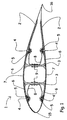
- FIG. 1 shows a blade 1 for a wind-energy plant.
- the blade 1 comprises a blade shell 2 that ia constitutes the aerodynamically active part of the blade.
- the blade shell 2 comprises upper principal laminates 7, by which the essential part of the strength and rigidity of the blade are achieved.
- two essentially longitudinally extending beams 3 are arranged for bracing purposes.
- the fore edge and the aft edge of the blade are indicated by reference numerals 15 and 16, respectively.
- metallic receptors 4 are provided at the exterior surface of the blade shell 2.
- the term "receptor" is to be understood an electrically conductive object being configured with a view to capturing and conducting a lightning current.
- connection 8 the receptors 4 are connected to lightning arresters 9.
- Receptors 4, connections 8 and arresters 9 are metallic objects configured for being able to conduct a lightning current that may be extremely powerful. The lightning current must be conducted reliably from the lightning currents 9 to a ground connection, including optionally across a spark gap since otherwise the current may damage the blade.
- the receptors 4 are connected to connections 8 by terminals 5 that are configured for reliably transferring a lightning current from the receptor 4 to the connection 8.
- the principal laminates 7 comprise not shown electrically conductive fibres, such as carbon fibres, steel fibres, etch.
- Electrically conductive means 6 are arranged that are connected to a large portion of the conductive fibres in principal laminates, and being in the shown case connected to a lightning arrester 9 via a receptor 4 and a connection 8. This is a practical embodiment, the receptor being already connected to the lightning arrestor 9; however, the conductive means 6 may also be connected to a lightning arrestor in some other manner.
- the conductive means 6 and hence the conductive fibres are connected to the lightning arrester 6, the fibres, the conductive means and the lightning arrester will have the same potential, thereby at least reducing the risk of a lightning current in the lightning arrestor transferring to the fibres of the laminate 7.
- the receptors 4 are preferably arranged next to the principal laminates 7 so as not to compromise the strength thereof. The number and location of the receptors 4 are selected to be in accordance with the dimensions of the blade 1.
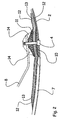
- FIG. 2 shows a blade shell 2 comprising a principal laminate 7, wherein not shown electrically conductive fibres are shown.
- a cylindrical receptor 4 is provided next to the principal laminate 7, a cylindrical receptor 4 is provided.
- a metallic connecting element 10 is arranged that may be secured by means of glue.
- a heavy grid 12 of cupper is provided: the grid 12 is conveyed across a part of the principal laminate 7 where it is in contact with the not shown electrically conductive fibres - either directly or by means of not shown electrically conductive means.
- a number of mats 13 are arranged that may be of carbon fibres or other suitable material, and yet a grid of cupper.
- a metallic connecting element 11 provided with thread is arranged on top of the layers of grid 12 and mats 13, yet a metallic connecting element 11 provided with thread is arranged.
- the receptor 4 is also configured with threads for cooperating with the connecting element 11 through the connecting element 10, grid 12 and mats 13.
- clamping together of the receptor 4 and the connecting element 11 can be used to clamp the connecting elements 10, 11 tightly around grid 12 and mats 13, whereby good electrical connection is achieved. This can be further improved and ensured by soldering the grids 12 to the respective connecting elements 10 and 11.
- the receptor 4 is connected to a connection 8 for earthing. To improve securing of connection 8, it is arranged in a gluing 14.
- the metallic connecting elements 10 and 11 can be configured of eg a bronze-alloy; but other metals may also be used. The same applies to grids 12 and mats 13; the essential being good electrical conductivity.
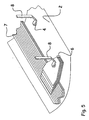
- Figure 3 shows an exemplified embodiment of mats 13 and grids 12, wherein they are stepped up in thickness and narrowed in width in the course from the laminate 7 towards the connecting element 11.
- the one grid 12 is arranged in contact with not shown electrically conductive fibres in the laminate 7, and the grids 12 and the mats 13 thus constitute electrically conductive means 6 that also connect the conductive fibres to each other.
- Figure 4 shows a receptor 4 cast integrally with a laminate for a blade. Exteriorly a layer of gel coat 10 is provided.
- the laminate comprises electrically non-conductive fibres 20 in mat-shape and electrically conductive fibres 21 arranged in mats 18. Both fibres 20 and fibres 21 are arranged in batches 18, wherein the binding ensures electrically conductive connection between all of the fibres, albeit they are situated essentially in parallel.
- the receptor 4 is connected to the fibres 21 by electrically conductive glue 22.
- a connection 8 is coupled to a not shown lightning arrester for earthing and by means of a screw it is connected to the receptor 4, whereby both receptor 4 and electrically conductive fibres 21 are connected to ground.
- the shown fibre mats may conveniently be the so-called hybrid mats that are structured in a pattern with at least one roving of one type of fibre and at least one roving of another type of fibre.
- the fibres 20 can have a pattern of alternately seven rovings of glass fibres and one roving of carbon fibres.
- electrically conductive means are arranged, eg in the form of electrically conductive fibres, eg carbon fibres, for creating an electrical connection and equalisation of potential between the fibres.
- the electrically conductive means can be a metal grid or a metal plate or the like.
- Fibres 21 may be steel fibres.
- FIG. 5 shows a blade shell 2 comprising a laminate 7 that contains not shown electrically conductive fibres, said fibres being electrically connected via electrically conductive means 6 from where they are coupled to a connection 8.
- a receptor 4 is arranged that is connected to a connection 8. Both connections 8 are connected to ground.
- Figure 6 shows a blade shell 2, wherein a receptor 4 is arranged for capturing lightnings at the outside at the outside thereof, and wherein the receptor is arranged in that part of the blade shell that is not constituted by the principal laminate 7. Via a connection 8, the receptor 4 is connected to ground. Not shown electrically conductive fibres in the laminate 7 are connected to a grid 13 of metal and likewise connected to the connection 8. Preferably the grid can be glued to the laminate.
- Figure 7 shows a principal laminate 7 containing at least a portion of not shown electrically conductive fibres, eg in the form of at least one hybrid mat, wherein the fibres are connected to electrically conductive means 6.
- the means 6 can be a grid, a mat or a plate and configured essentially of an electrically conductive material.
- the electrically conductive fibres can be cross-connected by electrically conductive means throughout the entire length of the blade or in sections.
- Figure 8 shows a blade shell 2 with internal bracings in the form of beams 3. Exteriorly of the blade shell 2, elongate metal members 23 are arranged - the so-called diverter strips - that are connected to a receptor 4. Hereby great area coverage of the surface is accomplished by means of relatively few receptors 4, which may be advantageous in case of large blades.
- the metal objects 23 can be secured by gluing or cast integrally.
- Figure 9 shows bracing beams 3 and receptors 24 and 25 that can be integral with the fore edge and/or the aft edge of the blade and will have an expanse corresponding at least to half the length of the blade.
Landscapes
- Engineering & Computer Science (AREA)
- Life Sciences & Earth Sciences (AREA)
- Sustainable Development (AREA)
- Sustainable Energy (AREA)
- Chemical & Material Sciences (AREA)
- Combustion & Propulsion (AREA)
- Mechanical Engineering (AREA)
- General Engineering & Computer Science (AREA)
- Wind Motors (AREA)
- Elimination Of Static Electricity (AREA)
Abstract
Description
- The invention relates to a method of lightning-proofing a blade of a wind-energy plant, which blade comprises a blade shell configured essentially as a fibre-reinforced laminate, which laminate comprises electrically conductive fibres, where the blade comprises at least one lightning arrester configured for conducting a lightning current, including preferably to ground. Also, the invention relates to a lightning-proofed blade and a wind-energy plant.
- It is known to provide blades for wind-energy plants with lightning receptors that are, inside the blade, in electric connection with a metallic lightning arrester that is able to connect a lightning current to earth. One example of this was described in
EP 0 783 629 B1 which is incorporated herein by this reference. Moreover it is known fromWO 00/14405 WO 00/14405 - As the demand for blades for wind-energy plants tends towards blades of increasing lengths, a need concurrently arises for manufacture of blades having increased rigidity and a comparatively lower weight. One way of achieving these properties it to combine various types of fibres in the laminate of the blades, for instance it is an option to combine glass fibres and carbon fibres, and likewise carbon fibres or glass fibres may advantageously be combined with steel fibres as known eg from
US 20020037409 . Combinations with other types of fibres are thus also possible and it is also an option to exclusively employ carbon fibres or other suitable fibre type. Combination of eg glass fibres with carbon fibres in a so-called hybrid laminate presents advantages, but still problems do arise. One of these problems is that some of the fibre types are electrically conductive, eg carbon fibres and steel fibres. A lightning strike directly into the laminate may cause damage to a blade comprising electrically conductive fibres, as they would conduct the current and hereby ia be greatly heated. This is particularly problematic in case of fibres having comparatively poor conductivity, such as carbon fibres, and in case of hybrid laminates with fibres in eg mat-shape, where the individual mat may eg have a small portion of electrically conductive fibres and a larger portion of eg glass fibres that are not electrically conductive. A further issue is that, albeit a lightning current is captured by a receptor and conducted to a lightning arrester, the conductive fibres in the laminate may cause the current to transfer into the laminate and hence cause damage thereto. - A method according to the invention as defined in
claim 1 may at least partially remedy the above-described problems. - When the electrically conductive fibres are connected to each other by electrically conductive means, and the at least one essentially massive first connecting element of metal is arranged internally of the blade on top of the electrically conductive means and in electrically conductive connection therewith, said connecting element being connected to the lightning arrestor the fibres will cooperate on the conduction of a lightning current. Hereby a suitable electrical connection is accomplished, where powerful currents can be conducted from the electrically conductive means to the lightning arrester. Hereby any damaging effect will be reduced.
- Simultaneously, the metallic receptor will serve as the primary lightning capturing device and reduce the risk of lightning strikes in the laminate. The receptor being connected to the lighting arrestor, the lightning current will predominately be earthed, while the risk of transfers to the laminate is minimised in that the electrically conductive fibres, being for the major part connected to each other, are also connected to the lightning arrestor whereby any difference in potential that may give rise to transfer is thereby equalised. The risk of lightning striking the laminate or transferring to the laminate from the lightning arrestor is thus minimised.
- According to one embodiment the receptor can be connected both to the lightning arrestor and to the electrically conductive fibres in the principal laminate, either via the electrically conductive means or directly or by a combination thereof. Hereby the receptor, which must always be of a sturdy configuration for conducting a lightning current, can also be used for connecting the conductive fibres in the laminate by means of the lightning conductor. Hereby a powerful current can also be conducted from the conductive fibres to the lightning arrester.
- According to a further embodiment, the receptor can be connected to the electrically conductive fibres in the principal laminate by a process that comprises welding, soldering or gluing by electrically conductive glue, eg silver glue. Hereby a safe electrical connection is accomplished that can be configured for conduction of powerful currents.
- According to a further embodiment at least one further essentially massive connecting element of metal can be arranged against the laminate, and the electrically conductive means are arranged on top of the second connecting element, and the first connecting element is arranged on top of the electrically conductive means, and the first connecting element and the receptor are configured for being clamped to each other through the second connecting element and the electrically conductive means by threads. Hereby it is accomplished that the first and the second connecting elements can be clamped around the electrically conductive means by means of the receptor, whereby good electrical connection is created from the electrically conductive means to the connecting elements.
- According to yet an embodiment the first connecting element and/or the second connecting element can be soldered, welded or glued with electrically conductive glue to the electrically conductive means for further improvement of the conductivity.
- According to yet an embodiment the principal laminate may both comprise fibres that are electrically conductive and fibres that are not electrically conductive. Hereby the fibre composition can be optimised in relation to the design of the blade and the load on the blade, since one may freely select fibres from both categories.
- According to an alternative embodiment the receptor can be moulded completely or partially into the laminate, including eg in connection with vacuum-injection of resin for bonding the laminate. Hereby processing of the blade is avoided following setting for mounting of the receptor.
- According to a preferred embodiment the electrically conductive means may comprise electrically conductive fibres, including in the form of at least one mat. This is advantageous in that, usually, such fibres are already employed in the laminate, and thus they are readily available. Moreover the fibres can be laminated to each other, and a strength contribution there from can be used to advantage, if so desired.
- According to an alternative embodiment the electrically conductive means may comprise at least a grid or a plate of metal. Hereby good conductivity is accomplished of the conductive means that are thus suitable for conducting powerful currents.
- According to yet an alternative embodiment a number of elongate metal elements can be arranged at the exterior surface of the blade for capturing lightning current and connected to the lightning arrester. Hereby increased reliability is accomplished that a lightning current is captured and conduction of it to the lightning arrester without the laminate being influenced or damaged.
- According to yet an embodiment, it is possible to arrange a number of receptors - both at the top surface and at the bottom surface of the blade, whereby increased reliability is accomplished that a lightning current is captured by a receptor. This may be advantageous in particular in case of long blades.
- According to a preferred embodiment, the receptors can be arranged approximately symmetrically about an axis, which axis - seen in a cross section of the blade, essentially at right angles to the longitudinal axis of the blade from root to tip - extends through the fore edge and aft edge of the blade. Hereby advantageous distribution of the receptors is accomplished thereby increasing the likelihood of a lightning current being captured.
- According to an alternative embodiment, the at least one receptor can be configured to be elongate and adapted for integration into or with the fore and/or aft edge(s) of the blade. Hereby it is possible to configure the receptor or receptors with a comparatively large surface thereby increasing the likelihood of a lightning current being captured.
- Such elongate receptor following the longitudinal direction of the blade, the receptor can be used as lightning arrester, at least along a part of the length of the blade. Hereby it is possible to avoid cumbersome mounting of electrical connections interiorly of the blade from receptor(s) to an internal lightning arrester.
- According to a preferred embodiment, the at least one receptor can preferably be arranged at that part of the blade shell that is not constituted by the principal laminate of the blade, and preferably in a position in proximity of the principal laminate. Hereby it is avoided that the principal laminate is weakened - eg by through-bores, and the receptor can be arranged in the remaining part of the blade shell instead, which is less important from a strength point of view. When arranged in such close proximity to the principal laminate which is where the electrically conductive fibres will preferably be used since, typically, they have a higher strength and rigidity than the other fibres, the protection of the principal laminate is enhanced due to the short distance to the receptor
- According to yet a preferred embodiment, the at least one receptor can preferably be arranged such that at least a part of the receptor is arranged in proximity of or at the external surface of the blade. Hereby an improved likelihood is achieved of the lightning currents being captured, since such rather free arrangement is more easily "detected" by a lightning.
- A further aspect of the invention relates to a wind-energy plant comprising at least one lightning-proofed blade, which blade is manufactured according to a method according to one or more of the above aspects. A further aspect relates to a lightning-proofed blade, which blade is also manufactured according to a method according to one or more of the above aspects. In both cases corresponding advantages are accomplished that are disclosed in respective teachings above.
- In the following the invention is disclosed in further detail by means of figures that illustrate exemplary embodiments of the invention:
-
Figure 1 is a cross-sectional view of a blade of a wind-energy plant; -
Figure 2 shows a section of a cross-section of a blade; -
Figure 3 is an isometric view of a section of interior details of a blade; -
Figure 4 is a section of a cross section of a blade; -
Figure 5 is an isometric view of a section of interior details of a blade; -
Figure 6 shows a section of a cross section of a blade; -
Figure 7 is an isometric view of a section of interior details of a blade; -
Figure 8 is an isometric view of a section of a blade; -
Figure 9 shows a cross section through a blade. -
Figure 1 shows ablade 1 for a wind-energy plant. Theblade 1 comprises ablade shell 2 that ia constitutes the aerodynamically active part of the blade. Theblade shell 2 comprises upperprincipal laminates 7, by which the essential part of the strength and rigidity of the blade are achieved. Internally of the blade, two essentially longitudinally extendingbeams 3 are arranged for bracing purposes. The fore edge and the aft edge of the blade are indicated byreference numerals blade 1,metallic receptors 4 are provided at the exterior surface of theblade shell 2. The term "receptor" is to be understood an electrically conductive object being configured with a view to capturing and conducting a lightning current. Viaconnections 8 thereceptors 4 are connected to lightning arresters 9.Receptors 4,connections 8 and arresters 9 are metallic objects configured for being able to conduct a lightning current that may be extremely powerful. The lightning current must be conducted reliably from the lightning currents 9 to a ground connection, including optionally across a spark gap since otherwise the current may damage the blade. Thereceptors 4 are connected toconnections 8 byterminals 5 that are configured for reliably transferring a lightning current from thereceptor 4 to theconnection 8. In thatblade 1, theprincipal laminates 7 comprise not shown electrically conductive fibres, such as carbon fibres, steel fibres, etch. Electrically conductive means 6 are arranged that are connected to a large portion of the conductive fibres in principal laminates, and being in the shown case connected to a lightning arrester 9 via areceptor 4 and aconnection 8. This is a practical embodiment, the receptor being already connected to the lightning arrestor 9; however, the conductive means 6 may also be connected to a lightning arrestor in some other manner. When the conductive means 6 and hence the conductive fibres are connected to thelightning arrester 6, the fibres, the conductive means and the lightning arrester will have the same potential, thereby at least reducing the risk of a lightning current in the lightning arrestor transferring to the fibres of thelaminate 7. As will appear fromFigure 1 , thereceptors 4 are preferably arranged next to theprincipal laminates 7 so as not to compromise the strength thereof. The number and location of thereceptors 4 are selected to be in accordance with the dimensions of theblade 1. -
Figure 2 shows ablade shell 2 comprising aprincipal laminate 7, wherein not shown electrically conductive fibres are shown. Next to theprincipal laminate 7, acylindrical receptor 4 is provided. Internally of theblade shell 2, a metallic connectingelement 10 is arranged that may be secured by means of glue. On top of the connectingelement 10, aheavy grid 12 of cupper is provided: thegrid 12 is conveyed across a part of theprincipal laminate 7 where it is in contact with the not shown electrically conductive fibres - either directly or by means of not shown electrically conductive means. On top of thegrid 12, a number ofmats 13 are arranged that may be of carbon fibres or other suitable material, and yet a grid of cupper. On top of the layers ofgrid 12 andmats 13, yet a metallic connectingelement 11 provided with thread is arranged. Thereceptor 4 is also configured with threads for cooperating with the connectingelement 11 through the connectingelement 10,grid 12 andmats 13. In this embodiment clamping together of thereceptor 4 and the connectingelement 11 can be used to clamp the connectingelements grid 12 andmats 13, whereby good electrical connection is achieved. This can be further improved and ensured by soldering thegrids 12 to the respective connectingelements receptor 4 is connected to aconnection 8 for earthing. To improve securing ofconnection 8, it is arranged in a gluing 14. The metallic connectingelements grids 12 andmats 13; the essential being good electrical conductivity. -
Figure 3 shows an exemplified embodiment ofmats 13 andgrids 12, wherein they are stepped up in thickness and narrowed in width in the course from thelaminate 7 towards the connectingelement 11. The onegrid 12 is arranged in contact with not shown electrically conductive fibres in thelaminate 7, and thegrids 12 and themats 13 thus constitute electricallyconductive means 6 that also connect the conductive fibres to each other. -
Figure 4 shows areceptor 4 cast integrally with a laminate for a blade. Exteriorly a layer ofgel coat 10 is provided. The laminate comprises electricallynon-conductive fibres 20 in mat-shape and electricallyconductive fibres 21 arranged inmats 18. Bothfibres 20 andfibres 21 are arranged inbatches 18, wherein the binding ensures electrically conductive connection between all of the fibres, albeit they are situated essentially in parallel. Thereceptor 4 is connected to thefibres 21 by electricallyconductive glue 22. Aconnection 8 is coupled to a not shown lightning arrester for earthing and by means of a screw it is connected to thereceptor 4, whereby bothreceptor 4 and electricallyconductive fibres 21 are connected to ground. The shown fibre mats may conveniently be the so-called hybrid mats that are structured in a pattern with at least one roving of one type of fibre and at least one roving of another type of fibre. For instance, thefibres 20 can have a pattern of alternately seven rovings of glass fibres and one roving of carbon fibres. At the top and/or bottom side(s) of such hybrid mat electrically conductive means are arranged, eg in the form of electrically conductive fibres, eg carbon fibres, for creating an electrical connection and equalisation of potential between the fibres. Alternatively, the electrically conductive means can be a metal grid or a metal plate or the like.Fibres 21 may be steel fibres. -
Figure 5 shows ablade shell 2 comprising alaminate 7 that contains not shown electrically conductive fibres, said fibres being electrically connected via electrically conductive means 6 from where they are coupled to aconnection 8. In theblade shell 2, areceptor 4 is arranged that is connected to aconnection 8. Bothconnections 8 are connected to ground. -
Figure 6 shows ablade shell 2, wherein areceptor 4 is arranged for capturing lightnings at the outside at the outside thereof, and wherein the receptor is arranged in that part of the blade shell that is not constituted by theprincipal laminate 7. Via aconnection 8, thereceptor 4 is connected to ground. Not shown electrically conductive fibres in thelaminate 7 are connected to agrid 13 of metal and likewise connected to theconnection 8. Preferably the grid can be glued to the laminate. -
Figure 7 shows aprincipal laminate 7 containing at least a portion of not shown electrically conductive fibres, eg in the form of at least one hybrid mat, wherein the fibres are connected to electricallyconductive means 6. Themeans 6 can be a grid, a mat or a plate and configured essentially of an electrically conductive material. The electrically conductive fibres can be cross-connected by electrically conductive means throughout the entire length of the blade or in sections. -
Figure 8 shows ablade shell 2 with internal bracings in the form ofbeams 3. Exteriorly of theblade shell 2,elongate metal members 23 are arranged - the so-called diverter strips - that are connected to areceptor 4. Hereby great area coverage of the surface is accomplished by means of relativelyfew receptors 4, which may be advantageous in case of large blades. The metal objects 23 can be secured by gluing or cast integrally. -
Figure 9 shows bracing beams 3 andreceptors - It will be understood that the invention as disclosed in the present description and figures can be modified or changed while continuing to be comprised by the scope of protection of the following claims.
Claims (18)
- A method of lightning-proofing a blade (1) of a wind-energy plant, which blade comprises a blade shell (2) comprising at least one fibre-reinforced principal laminate (7; 18), said principal laminate comprising electrically conductive fibres (21), wherein the blade comprises at least one lightning arrester (9) configured for conducting lightning current, including preferably to ground, comprising:- that at least a number of electrically conductive fibres within the same principal laminate are connected to each other by electrically conductive means (6, 12, 13); and- that at least one metallic receptor (4, 24, 25) is provided for capturing lightning current at or in proximity of the external surface of the blade; and- that the receptor is connected to the lightning arrestor; and- that a number of the electrically conductive fibres within the same principal laminate are via the electrically conductive means connected to the lightning arrestor for equalising the difference in potential between the lightning arrester and the electrically conductive fibres;wherein at least one essentially massive first connecting element (11) of metal is arranged internally in the blade on top of the electrically conductive means and in electrically conductive connection there with, said connecting element being connected to the lightning arrester.
- A method according to claim 1, wherein the receptor is connected both to the lightning arrester and to the electrically conductive fibres in the principal laminate, either via the electrically conductive means or directly by a combination thereof.
- A method according to claim 1 or 2, wherein the receptor is connected to the electrically conductive fibres in the principal laminate by a process that comprises welding, soldering or gluing with electrically conductive glue, eg silver glue.
- A method according to claim 1, wherein at least one second essentially massive connecting element (10) of metal is arranged in abutment against the laminate; and the electrically conductive means are arranged on top of the further connecting element; and the first connecting element (11) is arranged on top of the electrically conductive means; and that the first connecting element and the receptor are configured for being clamped to each other through the second connecting element and the electrically conductive means by means of threads.
- A method according to one or more of claims 1-4 wherein the first connecting element and/or the second connecting element is/are soldered, welded or glued with electrically conductive glue to the electrically conductive means.
- A method according to one or more of claims 1-5, wherein the principal laminate both comprises fibres that are electrically conductive and fibres (20) that are not electrically conductive.
- A method according to one or more of claims 1-6, wherein the receptor is cast completely or partially integral with the laminate, including eg in connection with vacuum-injection of resin for bonding the laminate.
- A method according to one or more of claims 1-7, wherein the electrically conductive means comprise electrically conductive fibres, including in the form of at least one mat.
- A method according to one or more of claims 1-8, wherein the electrically conductive means comprise at least a grid or a plate of metal.
- A method according to one or more of claims 1-9, wherein a number of elongate metal elements (23) are arranged at the external surface of the blade for capturing lightning current and are connected to the lightning arrester.
- A method according to one or mone of claims 1-10, wherein a number of receptors are arranged both at the upper side and the lower side of the blade.
- A method according to claim 11, wherein the receptors are arranged approximately symmetrically about an axis, said axis, seen in a cross sectional view of the blade essentially at right angles to the longitudinal axis of the blade from root to tip, extending through the fore edge (15) and the aft edge (16) of the blade.
- A method according to one or more of claims 1-10, wherein the at least one receptor is configured to be elongate and adapted for integration into or with the fore and/or aft edges of the blade.
- A method according to claim 13, wherein the receptor is used as lightning arrester at least on a part of the length of the blade.
- A method according to one or more of claims 1-14, wherein the at least one receptor is preferably used at that part of the blade shell that is not constituted of the principal laminate of the blade, and preferably in a position in proximity of the principal laminate.
- A method according to one or more of claims 1-15, wherein the at least one receptor is preferably arranged such that at least a part of the receptor is arranged in proximity of or at the external face of the blade.
- A wind-energy plant comprising at least one lightning-proofed blade (1), which blade comprises a blade shell (2) comprising at least one fibre-reinforced principal laminate (7, 18), which principal laminate comprise electrically conductive fibres (21), where the blade comprises at least one lightning arrester (9) configured for conducting lightning current, including preferably to ground, said blade being manufactured by a method according to any one of claims 1-16, wherein at least a number of the electrically conductive fibres within the same principal laminate are connected to each other by electrically conductive means (6, 12, 13), and wherein at least one receptor (4, 24, 25) is arranged for capturing lightning current at or in proximity of the external face of the blade; and wherein the receptor is connected to the lightning arrester, and a number of the electrically conductive fibres within the same principal laminate are via the electrically conductive means connected to the lightning arrester for equalising difference in potential between the lightning arrester and the electrically conductive fibres characterized in that at least one essentially massive first connecting element (11) of metal is arranged internally in the blade on top of the electrically conductive means and in electrically conductive connection there with, said connecting element being connected to the lightning arrester and in that said receptor is metallic.
- A lightning-proofed blade (1) for a wind-energy plant, said blade comprising a blade shell (2) comprising at least one fibre-reinforced principal laminate (7, 18), which principal laminate comprises electrically conductive fibres (21), wherein the blade comprises at least one lightning arrester (9) configured for conducting lightning current, including preferably to ground, dL said blade being manufactured by a method according to any one of claims 1-16, wherein at least a number of the electrically conductive fibres within the same principal laminate are connected to each other by electrically conductive means (6, 12, 13), and wherein at least one receptor (4, 24, 25) is arranged for capturing lightning current at or in proximity of the external surface of the blade, and wherein the receptor is connected to the lightning arrester, and a number of the electrically conductive fibres within the same principal laminate are via the electrically conductive means connected to the lightning arrestor, for equalising the difference in potential between the lightning arrester and the electrically conductive fibres characterized in that at least one essentially massive first connecting element (11) of metal is arranged internally in the blade on top of the electrically conductive means and in electrically conductive connection there with, said connecting element being connected to the lightning arrester and in that said receptor is metallic.
Applications Claiming Priority (2)
| Application Number | Priority Date | Filing Date | Title |
|---|---|---|---|
| DK200301329A DK176298B1 (en) | 2003-09-15 | 2003-09-15 | Method of lightning protection of a blade for a wind power plant, a lightning protection wing and a wind power plant with such a blade |
| PCT/DK2004/000602 WO2005026538A1 (en) | 2003-09-15 | 2004-09-10 | A method of lightning-proofing a blade for a wind-energy plant |
Publications (3)
| Publication Number | Publication Date |
|---|---|
| EP1664528A1 EP1664528A1 (en) | 2006-06-07 |
| EP1664528B1 true EP1664528B1 (en) | 2010-12-29 |
| EP1664528B2 EP1664528B2 (en) | 2019-11-27 |
Family
ID=34306688
Family Applications (1)
| Application Number | Title | Priority Date | Filing Date |
|---|---|---|---|
| EP04762822.7A Expired - Lifetime EP1664528B2 (en) | 2003-09-15 | 2004-09-10 | A method of lightning-proofing a blade for a wind-energy plant |
Country Status (10)
| Country | Link |
|---|---|
| US (1) | US7651320B2 (en) |
| EP (1) | EP1664528B2 (en) |
| CN (1) | CN100425828C (en) |
| AT (1) | ATE493581T1 (en) |
| AU (1) | AU2004272684B2 (en) |
| CA (1) | CA2538140C (en) |
| DE (1) | DE602004030806D1 (en) |
| DK (1) | DK176298B1 (en) |
| ES (1) | ES2358671T5 (en) |
| WO (1) | WO2005026538A1 (en) |
Cited By (12)
| Publication number | Priority date | Publication date | Assignee | Title |
|---|---|---|---|---|
| EP2543874A1 (en) | 2011-07-06 | 2013-01-09 | LM Wind Power A/S | A wind turbine blade |
| EP2930010A1 (en) | 2014-04-10 | 2015-10-14 | Nordex Energy GmbH | Belt assembly for a wind energy assembly rotor blade |
| EP2930353A1 (en) | 2014-04-10 | 2015-10-14 | Nordex Energy GmbH | Wind energy plant rotor blade with a potential equalisation arrangement |
| EP2930352A1 (en) | 2014-04-10 | 2015-10-14 | Nordex Energy GmbH | Wind energy plant rotor blade with a potential equalisation arrangement |
| DE102016001734A1 (en) * | 2015-11-19 | 2017-05-24 | DEHN + SÖHNE GmbH + Co. KG. | Method for influencing the lightning current distribution in electrical systems, which are integrated in rotor blades of wind turbines |
| EP3339633A1 (en) | 2016-12-22 | 2018-06-27 | Nordex Energy GmbH | Method for producing an equipotential bonding connection to a wind energy assembly rotor blade and wind energy assembly rotor blade with an equipotential bonding connection |
| EP3339632A1 (en) | 2016-12-22 | 2018-06-27 | Nordex Energy GmbH | Connection and fixing unit for a lightning receptor for integration with a wind energy assembly rotor blade |
| EP3611373A1 (en) | 2018-08-15 | 2020-02-19 | LM Wind Power International Technology II ApS | Lightning receptor bracket |
| US10584684B2 (en) | 2015-12-23 | 2020-03-10 | Lm Wp Patent Holding A/S | Wind turbine blades and potential equalization systems |
| WO2020115198A1 (en) | 2018-12-05 | 2020-06-11 | Lm Wind Power A/S | Attachment to a sandwich structure element |
| EP3967869A1 (en) | 2020-09-14 | 2022-03-16 | Siemens Gamesa Renewable Energy A/S | Wind turbine blade, wind turbine, method for fabrication of a wind turbine component and method for fabrication of a wind turbine blade |
| US11286912B2 (en) | 2017-08-25 | 2022-03-29 | Wobben Properties Gmbh | Wind turbine rotor blade and lightning protection system for a wind turbine rotor blade |
Families Citing this family (84)
| Publication number | Priority date | Publication date | Assignee | Title |
|---|---|---|---|---|
| CN1860654B (en) * | 2003-10-31 | 2011-04-20 | 维斯塔斯风力系统公司 | Potential equalizer |
| ES2255436B1 (en) * | 2004-11-11 | 2007-07-01 | Gamesa Eolica, S.A. | PARARRAYOS SYSTEM FOR AEROGENERATOR SHOVEL WITH CARBON FIBER LAMINATES. |
| EP1826402B1 (en) * | 2004-11-11 | 2016-08-24 | Gamesa Innovation & Technology, S.L. | Lightning conductor system for wind generator blades comprising carbon fibre laminates |
| ES2255454B1 (en) | 2004-12-15 | 2007-07-01 | Gamesa Eolica, S.A. | PARARRAYOS SYSTEM FOR AEROGENERATOR SHOVEL. |
| DE102005047959B4 (en) * | 2005-10-06 | 2008-01-31 | Nordex Energy Gmbh | Method for producing a bushing in a fiber composite material and rotor blade for a wind turbine with a bushing |
| JP4969098B2 (en) | 2005-12-21 | 2012-07-04 | 三菱重工業株式会社 | Windmill lightning protection device, method of assembling the lightning protection device, windmill blade including the lightning protection device, and windmill including the windmill blade |
| JP4699255B2 (en) * | 2006-03-24 | 2011-06-08 | 三菱重工業株式会社 | Windmill wing |
| GB0609166D0 (en) * | 2006-05-09 | 2006-06-21 | Airbus Uk Ltd | Apparatus for and method of inhibiting delamination |
| DK200600653A (en) * | 2006-05-09 | 2007-11-10 | Vestas Wind Sys As | Lightning protection system for a wind turbine blade, and method for producing a wind turbine blade with a lightning protection system |
| CN101668945B (en) * | 2007-02-19 | 2012-06-20 | 维斯塔斯风力系统有限公司 | Wind turbine rotor blade and method of manufacturing such rotor blade |
| FR2914622B1 (en) * | 2007-04-04 | 2009-05-15 | Airbus France Sas | AIRCRAFT COMPRISING STRUCTURE ENSURING STRUCTURAL AND ELECTRICAL FUNCTIONS |
| FR2924687B1 (en) * | 2007-12-11 | 2010-05-07 | Airbus France | AIRCRAFT AND AIRCRAFT SYSTEM COMPRISING SUCH A SYSTEM |
| ES2401531T3 (en) * | 2007-12-20 | 2013-04-22 | Vestas Wind Systems A/S | Wind turbine blade with lightning receptors comprising carbon nanotubes |
| US20090167024A1 (en) * | 2007-12-28 | 2009-07-02 | Thorsten Landau | Gluing of wind turbine internals to structural components |
| US8182227B2 (en) * | 2008-02-01 | 2012-05-22 | General Electric Company | Wind turbine blade with lightning receptor |
| EP2110552B2 (en) * | 2008-04-15 | 2018-12-26 | Siemens Aktiengesellschaft | Wind turbine blade with an integrated lightning conductor and method for manufacturing the same |
| ES2377669T3 (en) * | 2008-07-02 | 2012-03-29 | Siemens Aktiengesellschaft | Wind turbine blade with lightning receiver and method to protect the surface of a wind turbine blade |
| US8137074B2 (en) * | 2008-08-21 | 2012-03-20 | General Electric Company | Wind turbine lightning protection system |
| US7942640B2 (en) * | 2009-03-19 | 2011-05-17 | General Electric Company | Method and apparatus for use in protecting wind turbine blades from lightning damage |
| CA2758797C (en) * | 2009-04-17 | 2018-06-12 | 3M Innovative Properties Company | Lightning protection sheet with patterned conductor |
| PT2650210T (en) | 2009-04-17 | 2018-05-10 | 3M Innovative Properties Co | Lightning protection sheet with patterned discriminator |
| US8342805B2 (en) * | 2009-06-25 | 2013-01-01 | General Electric Company | Transversal conduction lightning protection system |
| GB0912016D0 (en) * | 2009-07-10 | 2009-08-19 | Airbus Operations Ltd | Edge glow protection for composite component |
| EP2518312A4 (en) * | 2009-12-24 | 2013-06-12 | Mitsubishi Heavy Ind Ltd | Wind wheel blade and wind-driven electricity generation device with same |
| JP2011137386A (en) * | 2009-12-25 | 2011-07-14 | Mitsubishi Heavy Ind Ltd | Wind turbine rotor blade and method of manufacturing wind turbine rotor blade |
| CN101793239A (en) * | 2010-03-19 | 2010-08-04 | 昆山华风风电科技有限公司 | Lightning protection device for blades of wind generating set |
| DE102010025546A1 (en) * | 2010-06-29 | 2011-12-29 | Suzlon Energy Gmbh | Nacelle paneling |
| US8727723B2 (en) | 2010-07-23 | 2014-05-20 | Erico International Corporation | Receptor for wind turbine blade lightning protection |
| ES2396839B1 (en) * | 2010-11-30 | 2014-01-02 | Gamesa Innovation & Technology, S.L. | PARARRAYOS SYSTEM FOR AEROGENERATOR SHOVEL WITH CARBON FIBER LAMINATES. |
| US8096765B2 (en) * | 2010-12-01 | 2012-01-17 | General Electric Company | Wind turbine rotor blades with enhanced lightning protection system |
| US20110142671A1 (en) * | 2010-12-01 | 2011-06-16 | General Electric Company | Wind turbine rotor blades with enhanced lightning protection system |
| CN102536677A (en) * | 2010-12-22 | 2012-07-04 | 上海艾郎风电科技发展有限公司 | Vane lightning arrestor for wind power generation |
| DE102011079240B4 (en) * | 2011-07-15 | 2018-09-06 | Carbon Rotec Gmbh & Co. Kg | Device and method for manufacturing a component |
| US8834117B2 (en) * | 2011-09-09 | 2014-09-16 | General Electric Company | Integrated lightning receptor system and trailing edge noise reducer for a wind turbine rotor blade |
| US20130149153A1 (en) * | 2011-12-09 | 2013-06-13 | Euros Entwicklungsgesellschaft Fur Windkraftanlagen Mbh | Wind turbine blade |
| CN102497715A (en) * | 2011-12-13 | 2012-06-13 | 湘电风能有限公司 | Electrostatic discharge device for wind turbine blades |
| CN102661240A (en) * | 2012-05-16 | 2012-09-12 | 国电联合动力技术有限公司 | Wind wheel vane anti-lightning device for wind generating set and mounting method thereof |
| TWI577886B (en) * | 2012-08-06 | 2017-04-11 | 渥班資產公司 | Carbon fiber reinforced plastic resistor sheet heating |
| DK2956662T3 (en) * | 2013-02-13 | 2017-10-16 | Vestas Wind Sys As | WIND TURBINE BLADES |
| DE102013107296B4 (en) | 2013-07-10 | 2015-03-19 | Senvion Se | Rotor blade with lightning rod |
| PL3024645T3 (en) * | 2013-07-26 | 2024-04-29 | Lm Wind Power A/S | A method of manufacturing at least part of a wind turbine blade |
| GB2519331A (en) * | 2013-10-17 | 2015-04-22 | Vestas Wind Sys As | Improvements relating to lightning protection systems for wind turbine blades |
| GB2521809A (en) * | 2013-10-17 | 2015-07-08 | Vestas Wind Sys As | Improvements relating to lightning protection systems for wind turbine blades |
| GB2519332A (en) * | 2013-10-17 | 2015-04-22 | Vestas Wind Sys As | Improvements relating to lightning protection systems for wind turbine blades |
| FR3012527B1 (en) * | 2013-10-30 | 2015-10-30 | Snecma | METALLIZING AN ELECTRICALLY INSULATING CASE OF AN AERONAUTICAL MOTOR |
| US9702255B2 (en) | 2013-11-26 | 2017-07-11 | Textron Innovations, Inc. | Propeller with lightening strike protection |
| DK2930357T3 (en) | 2014-04-10 | 2018-10-01 | Nordex Energy Gmbh | Rotor blade for wind energy systems and with a lightning conductor base |
| ES2689673T3 (en) * | 2014-04-10 | 2018-11-15 | Nordex Energy Gmbh | Wind turbine rotor blade with a lightning conductor and a power compensation element |
| US10316827B2 (en) * | 2014-11-11 | 2019-06-11 | General Electric Company | Conduit assembly for a lightning protection cable of a wind turbine rotor blade |
| US9816482B2 (en) * | 2014-11-17 | 2017-11-14 | General Electric Company | Spar cap for a wind turbine rotor blade |
| US9759183B2 (en) * | 2015-01-05 | 2017-09-12 | General Electric Company | System and method for attaching components to a web in a wind turbine rotor blade |
| JP6444797B2 (en) | 2015-03-31 | 2018-12-26 | 株式会社東芝 | Wind power generation system |
| ES2589185B1 (en) * | 2015-05-08 | 2017-09-18 | Gamesa Innovation & Technology, S.L. | Lightning rod system for wind turbine blades with conductive structural components |
| US9719495B2 (en) | 2015-05-13 | 2017-08-01 | General Electric Company | Lightning protection system for wind turbine rotor blades |
| ES2592323B1 (en) | 2015-05-26 | 2017-09-18 | Gamesa Innovation & Technology, S.L. | Lightning receiver for a wind turbine blade |
| WO2017033249A1 (en) * | 2015-08-24 | 2017-03-02 | 株式会社日立製作所 | Wind power generation device |
| JP6679738B2 (en) | 2016-01-29 | 2020-04-15 | ヴォッベン プロパティーズ ゲーエムベーハーWobben Properties Gmbh | Spur cap and manufacturing method |
| US10344743B2 (en) | 2016-05-13 | 2019-07-09 | Erico International Corporation | Lightning protection system and method for wind turbine blades |
| USD803163S1 (en) | 2016-05-13 | 2017-11-21 | Erico International Corporation | Tip receptor mount for lightning protection systems |
| ES2646015B1 (en) * | 2016-06-07 | 2018-09-20 | Gamesa Innovation & Technology, S.L. | Lightning rod system for wind turbine blades with optimized means of injecting lightning currents into the conductive components of their shells. |
| US10648456B2 (en) * | 2016-10-21 | 2020-05-12 | General Electric Company | Organic conductive elements for deicing and lightning protection of a wind turbine rotor blade |
| ES2687782A1 (en) * | 2017-04-28 | 2018-10-29 | Gamesa Innovation & Technology, S.L. | Method and evaluation system of a lightning rod system of a wind turbine comprising a plurality of blades manufactured with a composite reinforced with carbon fiber (Machine-translation by Google Translate, not legally binding) |
| EP3499020B1 (en) * | 2017-12-13 | 2021-08-25 | Nordex Energy SE & Co. KG | Rotor blade shell and method for producing a rotor blade shelfor a rotor blade |
| EP3581796B1 (en) | 2018-06-14 | 2022-03-23 | Siemens Gamesa Renewable Energy A/S | Stepped conductivity interface |
| JP6657314B2 (en) * | 2018-06-15 | 2020-03-04 | 三菱重工業株式会社 | Wind turbine blade protection structure and method of forming the same |
| ES2949381T3 (en) | 2018-07-09 | 2023-09-28 | Vestas Wind Sys As | Improvements related to wind turbine blades |
| EP3597911B1 (en) * | 2018-07-17 | 2021-08-25 | Siemens Gamesa Renewable Energy A/S | A wind turbine blade and a wind turbine |
| GB202002431D0 (en) * | 2020-02-21 | 2020-04-08 | Lm Wind Power As | Lightning protection system for a main laminate |
| DK3712425T3 (en) * | 2019-03-21 | 2024-11-04 | Siemens Gamesa Renewable Energy As | WIND TURBINE ROTOR BLADE-SPAR CAP, WIND TURBINE ROTOR BLADE AND WIND TURBINE |
| PT3719312T (en) * | 2019-04-03 | 2022-06-28 | Siemens Gamesa Renewable Energy As | WIND TURBINE AND WIND TURBINE BLADE |
| CN111775456A (en) * | 2020-07-07 | 2020-10-16 | 株洲时代新材料科技股份有限公司 | Manufacturing method of concave main beam wind power blade and concave main beam wind power blade |
| DK3943745T3 (en) * | 2020-07-22 | 2026-02-09 | Siemens Gamesa Renewable Energy Innovation & Technology SL | Lightning protection system for a carbon pultruded blade |
| WO2022023586A1 (en) | 2020-07-27 | 2022-02-03 | Nabrawind Technologies, Sl | System for protection against lightning strikes for a modular blade and method of forming a stack |
| EP4019772B1 (en) * | 2020-12-23 | 2024-10-30 | Polytech A/S | Ligthning protection system for a wind turbine blade |
| EP4019766A1 (en) * | 2020-12-23 | 2022-06-29 | Polytech A/S | A conductive connection |
| EP4074963A1 (en) * | 2021-04-14 | 2022-10-19 | Siemens Gamesa Renewable Energy A/S | Connector arrangement for a wind turbine down conductor, and wind turbine |
| MA71712A (en) * | 2021-05-04 | 2025-05-30 | Lm Wind Power A/S | MAIN LAMINATE OF A WIND TURBINE BLADE AND ASSOCIATED METHOD |
| CN117940663A (en) | 2021-08-06 | 2024-04-26 | 纳布拉温德科技有限公司 | Transition portion of composite laminate for modular blade |
| US20240410340A1 (en) * | 2021-12-10 | 2024-12-12 | Vestas Wind Systems A/S | Lightning protection system |
| EP4234928B1 (en) * | 2022-02-25 | 2024-09-11 | Siemens Gamesa Renewable Energy A/S | Wind turbine rotor blade and wind turbine |
| CN114526191A (en) * | 2022-03-07 | 2022-05-24 | 华能河南清洁能源有限公司 | Surface protection method and protection structure of wind power blade |
| WO2023241787A1 (en) * | 2022-06-14 | 2023-12-21 | Lm Wind Power A/S | Wind turbine blade with a lightning receptor |
| CN116877360B (en) * | 2022-06-29 | 2024-05-28 | 江苏金风科技有限公司 | Lightning protection device, lightning protection system, wind generating set and method |
| KR102786810B1 (en) * | 2023-02-27 | 2025-03-25 | 국립목포해양대학교산학협력단 | Blades Lightning Damage Prevention Receptor |
Family Cites Families (10)
| Publication number | Priority date | Publication date | Assignee | Title |
|---|---|---|---|---|
| US3923421A (en) * | 1974-12-19 | 1975-12-02 | United Technologies Corp | Lightning protected composite helicopter blade |
| US4502092A (en) * | 1982-09-30 | 1985-02-26 | The Boeing Company | Integral lightning protection system for composite aircraft skins |
| GB9215827D0 (en) * | 1992-07-24 | 1992-09-09 | British Aerospace | A lightning shield |
| DK9400343U4 (en) * | 1994-09-07 | 1995-10-13 | Bonus Energy As | Lightning protection of wind turbine wings |
| DE4445899A1 (en) * | 1994-12-22 | 1996-06-27 | Autoflug Energietech Gmbh | Wind turbine generator with lighting protection |
| FR2741590B1 (en) * | 1995-11-29 | 1998-01-30 | Eurocopter France | BLADE WITH REINFORCED PROTECTION AGAINST LIGHTNING, FOR ROTOR OF A GIRAVION |
| DE19748716C1 (en) * | 1997-11-05 | 1998-11-12 | Aerodyn Eng Gmbh | Rotor blade heater and lightning diverter for wind turbine operation in sub-zero conditions |
| DK173460B2 (en) * | 1998-09-09 | 2004-08-30 | Lm Glasfiber As | Windmill wing with lightning conductor |
| DK173607B1 (en) * | 1999-06-21 | 2001-04-30 | Lm Glasfiber As | Wind turbine blade with lightning de-icing system |
| ES2317896T3 (en) * | 2000-04-10 | 2009-05-01 | Jomitek Aps | SYSTEM OF PROTECTION AGAINST RAYS, FOR EXAMPLE, FOR AN AEROGENERATOR, AEROGENERATOR SHOVEL THAT PRESENTS A SYSTEM OF PROTECTION AGAINST RAYS, PROCEDURE OF CREATION OF A SYSTEM OF PROTECTION AGAINST RAYS AND ITS USE. |
-
2003
- 2003-09-15 DK DK200301329A patent/DK176298B1/en not_active IP Right Cessation
-
2004
- 2004-09-10 AU AU2004272684A patent/AU2004272684B2/en not_active Expired
- 2004-09-10 AT AT04762822T patent/ATE493581T1/en not_active IP Right Cessation
- 2004-09-10 WO PCT/DK2004/000602 patent/WO2005026538A1/en not_active Ceased
- 2004-09-10 CA CA2538140A patent/CA2538140C/en not_active Expired - Lifetime
- 2004-09-10 CN CNB2004800301018A patent/CN100425828C/en not_active Expired - Lifetime
- 2004-09-10 EP EP04762822.7A patent/EP1664528B2/en not_active Expired - Lifetime
- 2004-09-10 ES ES04762822T patent/ES2358671T5/en not_active Expired - Lifetime
- 2004-09-10 US US10/572,293 patent/US7651320B2/en not_active Expired - Lifetime
- 2004-09-10 DE DE602004030806T patent/DE602004030806D1/en not_active Expired - Lifetime
Cited By (16)
| Publication number | Priority date | Publication date | Assignee | Title |
|---|---|---|---|---|
| WO2013004805A1 (en) | 2011-07-06 | 2013-01-10 | Lm Wind Power A/S | A wind turbine blade |
| EP2543874A1 (en) | 2011-07-06 | 2013-01-09 | LM Wind Power A/S | A wind turbine blade |
| EP2930010A1 (en) | 2014-04-10 | 2015-10-14 | Nordex Energy GmbH | Belt assembly for a wind energy assembly rotor blade |
| EP2930353A1 (en) | 2014-04-10 | 2015-10-14 | Nordex Energy GmbH | Wind energy plant rotor blade with a potential equalisation arrangement |
| EP2930352A1 (en) | 2014-04-10 | 2015-10-14 | Nordex Energy GmbH | Wind energy plant rotor blade with a potential equalisation arrangement |
| DE102016001734A1 (en) * | 2015-11-19 | 2017-05-24 | DEHN + SÖHNE GmbH + Co. KG. | Method for influencing the lightning current distribution in electrical systems, which are integrated in rotor blades of wind turbines |
| DE102016001734B4 (en) | 2015-11-19 | 2023-11-09 | Dehn Se | Method for influencing the lightning current distribution in electrical systems that are integrated into the rotor blades of wind turbines |
| US10584684B2 (en) | 2015-12-23 | 2020-03-10 | Lm Wp Patent Holding A/S | Wind turbine blades and potential equalization systems |
| EP3339633A1 (en) | 2016-12-22 | 2018-06-27 | Nordex Energy GmbH | Method for producing an equipotential bonding connection to a wind energy assembly rotor blade and wind energy assembly rotor blade with an equipotential bonding connection |
| EP3339632A1 (en) | 2016-12-22 | 2018-06-27 | Nordex Energy GmbH | Connection and fixing unit for a lightning receptor for integration with a wind energy assembly rotor blade |
| US11286912B2 (en) | 2017-08-25 | 2022-03-29 | Wobben Properties Gmbh | Wind turbine rotor blade and lightning protection system for a wind turbine rotor blade |
| EP3611373A1 (en) | 2018-08-15 | 2020-02-19 | LM Wind Power International Technology II ApS | Lightning receptor bracket |
| WO2020115198A1 (en) | 2018-12-05 | 2020-06-11 | Lm Wind Power A/S | Attachment to a sandwich structure element |
| WO2022053449A1 (en) | 2020-09-14 | 2022-03-17 | Siemens Gamesa Renewable Energy A/S | Wind turbine blade, wind turbine, method for fabrication of a wind turbine component and method for fabrication of a wind turbine blade |
| EP3967869A1 (en) | 2020-09-14 | 2022-03-16 | Siemens Gamesa Renewable Energy A/S | Wind turbine blade, wind turbine, method for fabrication of a wind turbine component and method for fabrication of a wind turbine blade |
| US12560145B2 (en) | 2020-09-14 | 2026-02-24 | Siemens Gamesa Renewable Energy A/S | Wind turbine blade, wind turbine, method for fabrication of a wind turbine component and method for fabrication of a wind turbine blade |
Also Published As
| Publication number | Publication date |
|---|---|
| CN100425828C (en) | 2008-10-15 |
| CN1867772A (en) | 2006-11-22 |
| WO2005026538A1 (en) | 2005-03-24 |
| DK200301329A (en) | 2005-03-16 |
| CA2538140A1 (en) | 2005-03-24 |
| ES2358671T5 (en) | 2020-07-06 |
| US20060280613A1 (en) | 2006-12-14 |
| AU2004272684A1 (en) | 2005-03-24 |
| ES2358671T3 (en) | 2011-05-12 |
| AU2004272684B2 (en) | 2010-01-14 |
| EP1664528A1 (en) | 2006-06-07 |
| DE602004030806D1 (en) | 2011-02-10 |
| US7651320B2 (en) | 2010-01-26 |
| DK176298B1 (en) | 2007-06-18 |
| CA2538140C (en) | 2012-10-23 |
| EP1664528B2 (en) | 2019-11-27 |
| ATE493581T1 (en) | 2011-01-15 |
Similar Documents
| Publication | Publication Date | Title |
|---|---|---|
| EP1664528B2 (en) | A method of lightning-proofing a blade for a wind-energy plant | |
| CN108700041B (en) | Wind turbine blade and potential equalising system | |
| US9689377B2 (en) | Wind turbine rotor blade having an electrical heating device and a plurality of lightning conductors | |
| US7729100B2 (en) | Lightning conductor system for wind generator blades comprising carbon fibre laminates | |
| US10330087B2 (en) | Lightning protection system for wind turbine blades with an effective injection area to carbon fiber laminates and a balanced lightning current and voltage distribution between different conductive paths | |
| US10844844B2 (en) | Carbon blade for wind power generator with multi-down conductor | |
| KR20130093529A (en) | Wind turbine blade for a wind turbine | |
| CN103329379A (en) | Wind turbine blade | |
| US20110293437A1 (en) | Wind turbine blade with a conductively doped coating for lightning protection of the wind turbine blade and method for manufacturing the wind turbine blade | |
| EP3726049A1 (en) | Rotor blade and method for manufacturing a rotor blade | |
| CN119982319A (en) | Wind turbine blades and wind turbines | |
| EP2708740B1 (en) | Wind turbine rotor blade with an electric heating device and a lightning conductor | |
| US11614077B2 (en) | Wind turbine blade for a wind turbine and method of manufacturing a wind turbine blade | |
| EP2735042B1 (en) | Energy storage module | |
| CN113167219A (en) | Spar structure with integrated lower conductor element for lightning protection system | |
| CN109935772A (en) | A battery box, its battery module, and a conductive connecting sheet | |
| CN101094986A (en) | Lightning conductor system for wind generator blades comprising carbon fibre laminates | |
| EP4428362B1 (en) | Wind turbine blade integrating a lightning protection system | |
| CN118434971A (en) | Lightning protection system for segmented wind turbine blades | |
| EP4166780A1 (en) | A rotor blade lightning protection system with spark-gaps for equipotential bonds | |
| US12352243B1 (en) | Wind turbine blade integrating a lightning protection system | |
| CN217239770U (en) | Lightning protection grounding fixture that long service life and intensity are high | |
| CN204793283U (en) | Take electrical connector's carbon fiber plate | |
| CN121408131A (en) | Wind turbine blades with integrated lightning protection system | |
| WO2025158138A2 (en) | Lightning protection for wind-turbine blades |
Legal Events
| Date | Code | Title | Description |
|---|---|---|---|
| PUAI | Public reference made under article 153(3) epc to a published international application that has entered the european phase |
Free format text: ORIGINAL CODE: 0009012 |
|
| 17P | Request for examination filed |
Effective date: 20060314 |
|
| AK | Designated contracting states |
Kind code of ref document: A1 Designated state(s): AT BE BG CH CY CZ DE DK EE ES FI FR GB GR HU IE IT LI LU MC NL PL PT RO SE SI SK TR |
|
| 17Q | First examination report despatched |
Effective date: 20060901 |
|
| DAX | Request for extension of the european patent (deleted) | ||
| GRAP | Despatch of communication of intention to grant a patent |
Free format text: ORIGINAL CODE: EPIDOSNIGR1 |
|
| GRAS | Grant fee paid |
Free format text: ORIGINAL CODE: EPIDOSNIGR3 |
|
| GRAA | (expected) grant |
Free format text: ORIGINAL CODE: 0009210 |
|
| AK | Designated contracting states |
Kind code of ref document: B1 Designated state(s): AT BE BG CH CY CZ DE DK EE ES FI FR GB GR HU IE IT LI LU MC NL PL PT RO SE SI SK TR |
|
| REG | Reference to a national code |
Ref country code: GB Ref legal event code: FG4D |
|
| REG | Reference to a national code |
Ref country code: CH Ref legal event code: EP |
|
| REG | Reference to a national code |
Ref country code: IE Ref legal event code: FG4D |
|
| REF | Corresponds to: |
Ref document number: 602004030806 Country of ref document: DE Date of ref document: 20110210 Kind code of ref document: P |
|
| REG | Reference to a national code |
Ref country code: DE Ref legal event code: R096 Ref document number: 602004030806 Country of ref document: DE Effective date: 20110210 |
|
| REG | Reference to a national code |
Ref country code: NL Ref legal event code: VDEP Effective date: 20101229 |
|
| REG | Reference to a national code |
Ref country code: ES Ref legal event code: FG2A Ref document number: 2358671 Country of ref document: ES Kind code of ref document: T3 Effective date: 20110429 |
|
| PG25 | Lapsed in a contracting state [announced via postgrant information from national office to epo] |
Ref country code: SI Free format text: LAPSE BECAUSE OF FAILURE TO SUBMIT A TRANSLATION OF THE DESCRIPTION OR TO PAY THE FEE WITHIN THE PRESCRIBED TIME-LIMIT Effective date: 20101229 Ref country code: BG Free format text: LAPSE BECAUSE OF FAILURE TO SUBMIT A TRANSLATION OF THE DESCRIPTION OR TO PAY THE FEE WITHIN THE PRESCRIBED TIME-LIMIT Effective date: 20110329 Ref country code: AT Free format text: LAPSE BECAUSE OF FAILURE TO SUBMIT A TRANSLATION OF THE DESCRIPTION OR TO PAY THE FEE WITHIN THE PRESCRIBED TIME-LIMIT Effective date: 20101229 Ref country code: FI Free format text: LAPSE BECAUSE OF FAILURE TO SUBMIT A TRANSLATION OF THE DESCRIPTION OR TO PAY THE FEE WITHIN THE PRESCRIBED TIME-LIMIT Effective date: 20101229 Ref country code: CY Free format text: LAPSE BECAUSE OF FAILURE TO SUBMIT A TRANSLATION OF THE DESCRIPTION OR TO PAY THE FEE WITHIN THE PRESCRIBED TIME-LIMIT Effective date: 20101229 Ref country code: SE Free format text: LAPSE BECAUSE OF FAILURE TO SUBMIT A TRANSLATION OF THE DESCRIPTION OR TO PAY THE FEE WITHIN THE PRESCRIBED TIME-LIMIT Effective date: 20101229 |
|
| PG25 | Lapsed in a contracting state [announced via postgrant information from national office to epo] |
Ref country code: GR Free format text: LAPSE BECAUSE OF FAILURE TO SUBMIT A TRANSLATION OF THE DESCRIPTION OR TO PAY THE FEE WITHIN THE PRESCRIBED TIME-LIMIT Effective date: 20110330 Ref country code: PT Free format text: LAPSE BECAUSE OF FAILURE TO SUBMIT A TRANSLATION OF THE DESCRIPTION OR TO PAY THE FEE WITHIN THE PRESCRIBED TIME-LIMIT Effective date: 20110429 Ref country code: CZ Free format text: LAPSE BECAUSE OF FAILURE TO SUBMIT A TRANSLATION OF THE DESCRIPTION OR TO PAY THE FEE WITHIN THE PRESCRIBED TIME-LIMIT Effective date: 20101229 Ref country code: EE Free format text: LAPSE BECAUSE OF FAILURE TO SUBMIT A TRANSLATION OF THE DESCRIPTION OR TO PAY THE FEE WITHIN THE PRESCRIBED TIME-LIMIT Effective date: 20101229 Ref country code: BE Free format text: LAPSE BECAUSE OF FAILURE TO SUBMIT A TRANSLATION OF THE DESCRIPTION OR TO PAY THE FEE WITHIN THE PRESCRIBED TIME-LIMIT Effective date: 20101229 |
|
| PG25 | Lapsed in a contracting state [announced via postgrant information from national office to epo] |
Ref country code: PL Free format text: LAPSE BECAUSE OF FAILURE TO SUBMIT A TRANSLATION OF THE DESCRIPTION OR TO PAY THE FEE WITHIN THE PRESCRIBED TIME-LIMIT Effective date: 20101229 Ref country code: RO Free format text: LAPSE BECAUSE OF FAILURE TO SUBMIT A TRANSLATION OF THE DESCRIPTION OR TO PAY THE FEE WITHIN THE PRESCRIBED TIME-LIMIT Effective date: 20101229 Ref country code: NL Free format text: LAPSE BECAUSE OF FAILURE TO SUBMIT A TRANSLATION OF THE DESCRIPTION OR TO PAY THE FEE WITHIN THE PRESCRIBED TIME-LIMIT Effective date: 20101229 Ref country code: SK Free format text: LAPSE BECAUSE OF FAILURE TO SUBMIT A TRANSLATION OF THE DESCRIPTION OR TO PAY THE FEE WITHIN THE PRESCRIBED TIME-LIMIT Effective date: 20101229 |
|
| PLBI | Opposition filed |
Free format text: ORIGINAL CODE: 0009260 |
|
| PG25 | Lapsed in a contracting state [announced via postgrant information from national office to epo] |
Ref country code: DK Free format text: LAPSE BECAUSE OF FAILURE TO SUBMIT A TRANSLATION OF THE DESCRIPTION OR TO PAY THE FEE WITHIN THE PRESCRIBED TIME-LIMIT Effective date: 20101229 |
|
| PLAX | Notice of opposition and request to file observation + time limit sent |
Free format text: ORIGINAL CODE: EPIDOSNOBS2 |
|
| 26 | Opposition filed |
Opponent name: ENERCON GMBH Effective date: 20110929 |
|
| REG | Reference to a national code |
Ref country code: DE Ref legal event code: R026 Ref document number: 602004030806 Country of ref document: DE Effective date: 20110929 |
|
| PLAF | Information modified related to communication of a notice of opposition and request to file observations + time limit |
Free format text: ORIGINAL CODE: EPIDOSCOBS2 |
|
| PLBB | Reply of patent proprietor to notice(s) of opposition received |
Free format text: ORIGINAL CODE: EPIDOSNOBS3 |
|
| PG25 | Lapsed in a contracting state [announced via postgrant information from national office to epo] |
Ref country code: MC Free format text: LAPSE BECAUSE OF NON-PAYMENT OF DUE FEES Effective date: 20110930 |
|
| REG | Reference to a national code |
Ref country code: CH Ref legal event code: PL |
|
| PG25 | Lapsed in a contracting state [announced via postgrant information from national office to epo] |
Ref country code: IT Free format text: LAPSE BECAUSE OF FAILURE TO SUBMIT A TRANSLATION OF THE DESCRIPTION OR TO PAY THE FEE WITHIN THE PRESCRIBED TIME-LIMIT Effective date: 20101229 |
|
| REG | Reference to a national code |
Ref country code: IE Ref legal event code: MM4A |
|
| REG | Reference to a national code |
Ref country code: FR Ref legal event code: ST Effective date: 20120531 |
|
| PG25 | Lapsed in a contracting state [announced via postgrant information from national office to epo] |
Ref country code: IE Free format text: LAPSE BECAUSE OF NON-PAYMENT OF DUE FEES Effective date: 20110910 Ref country code: LI Free format text: LAPSE BECAUSE OF NON-PAYMENT OF DUE FEES Effective date: 20110930 Ref country code: CH Free format text: LAPSE BECAUSE OF NON-PAYMENT OF DUE FEES Effective date: 20110930 |
|
| PG25 | Lapsed in a contracting state [announced via postgrant information from national office to epo] |
Ref country code: FR Free format text: LAPSE BECAUSE OF NON-PAYMENT OF DUE FEES Effective date: 20110930 |
|
| PG25 | Lapsed in a contracting state [announced via postgrant information from national office to epo] |
Ref country code: LU Free format text: LAPSE BECAUSE OF NON-PAYMENT OF DUE FEES Effective date: 20110910 |
|
| PG25 | Lapsed in a contracting state [announced via postgrant information from national office to epo] |
Ref country code: TR Free format text: LAPSE BECAUSE OF FAILURE TO SUBMIT A TRANSLATION OF THE DESCRIPTION OR TO PAY THE FEE WITHIN THE PRESCRIBED TIME-LIMIT Effective date: 20101229 |
|
| PG25 | Lapsed in a contracting state [announced via postgrant information from national office to epo] |
Ref country code: HU Free format text: LAPSE BECAUSE OF FAILURE TO SUBMIT A TRANSLATION OF THE DESCRIPTION OR TO PAY THE FEE WITHIN THE PRESCRIBED TIME-LIMIT Effective date: 20101229 |
|
| APBM | Appeal reference recorded |
Free format text: ORIGINAL CODE: EPIDOSNREFNO |
|
| APBP | Date of receipt of notice of appeal recorded |
Free format text: ORIGINAL CODE: EPIDOSNNOA2O |
|
| APAH | Appeal reference modified |
Free format text: ORIGINAL CODE: EPIDOSCREFNO |
|
| APBM | Appeal reference recorded |
Free format text: ORIGINAL CODE: EPIDOSNREFNO |
|
| APBP | Date of receipt of notice of appeal recorded |
Free format text: ORIGINAL CODE: EPIDOSNNOA2O |
|
| APBQ | Date of receipt of statement of grounds of appeal recorded |
Free format text: ORIGINAL CODE: EPIDOSNNOA3O |
|
| APBU | Appeal procedure closed |
Free format text: ORIGINAL CODE: EPIDOSNNOA9O |
|
| PUAH | Patent maintained in amended form |
Free format text: ORIGINAL CODE: 0009272 |
|
| STAA | Information on the status of an ep patent application or granted ep patent |
Free format text: STATUS: PATENT MAINTAINED AS AMENDED |
|
| 27A | Patent maintained in amended form |
Effective date: 20191127 |
|
| AK | Designated contracting states |
Kind code of ref document: B2 Designated state(s): AT BE BG CH CY CZ DE DK EE ES FI FR GB GR HU IE IT LI LU MC NL PL PT RO SE SI SK TR |
|
| REG | Reference to a national code |
Ref country code: DE Ref legal event code: R102 Ref document number: 602004030806 Country of ref document: DE |
|
| REG | Reference to a national code |
Ref country code: ES Ref legal event code: DC2A Ref document number: 2358671 Country of ref document: ES Kind code of ref document: T5 Effective date: 20200706 |
|
| P01 | Opt-out of the competence of the unified patent court (upc) registered |
Effective date: 20230522 |
|
| PGFP | Annual fee paid to national office [announced via postgrant information from national office to epo] |
Ref country code: GB Payment date: 20230823 Year of fee payment: 20 |
|
| PGFP | Annual fee paid to national office [announced via postgrant information from national office to epo] |
Ref country code: DE Payment date: 20230822 Year of fee payment: 20 |
|
| PGFP | Annual fee paid to national office [announced via postgrant information from national office to epo] |
Ref country code: ES Payment date: 20231002 Year of fee payment: 20 |
|
| REG | Reference to a national code |
Ref country code: DE Ref legal event code: R071 Ref document number: 602004030806 Country of ref document: DE |
|
| REG | Reference to a national code |
Ref country code: ES Ref legal event code: FD2A Effective date: 20240927 |
|
| REG | Reference to a national code |
Ref country code: GB Ref legal event code: PE20 Expiry date: 20240909 |
|
| PG25 | Lapsed in a contracting state [announced via postgrant information from national office to epo] |
Ref country code: GB Free format text: LAPSE BECAUSE OF EXPIRATION OF PROTECTION Effective date: 20240909 |
|
| PG25 | Lapsed in a contracting state [announced via postgrant information from national office to epo] |
Ref country code: ES Free format text: LAPSE BECAUSE OF EXPIRATION OF PROTECTION Effective date: 20240911 |
|
| PG25 | Lapsed in a contracting state [announced via postgrant information from national office to epo] |
Ref country code: GB Free format text: LAPSE BECAUSE OF EXPIRATION OF PROTECTION Effective date: 20240909 Ref country code: ES Free format text: LAPSE BECAUSE OF EXPIRATION OF PROTECTION Effective date: 20240911 |