EP2543856A2 - Verfahren zur Steuerung eines aufgeladenen Verbrennungsmotors - Google Patents
Verfahren zur Steuerung eines aufgeladenen Verbrennungsmotors Download PDFInfo
- Publication number
- EP2543856A2 EP2543856A2 EP12175211A EP12175211A EP2543856A2 EP 2543856 A2 EP2543856 A2 EP 2543856A2 EP 12175211 A EP12175211 A EP 12175211A EP 12175211 A EP12175211 A EP 12175211A EP 2543856 A2 EP2543856 A2 EP 2543856A2
- Authority
- EP
- European Patent Office
- Prior art keywords
- supercharging
- function
- internal combustion
- combustion engine
- control method
- Prior art date
- Legal status (The legal status is an assumption and is not a legal conclusion. Google has not performed a legal analysis and makes no representation as to the accuracy of the status listed.)
- Granted
Links
- 238000002485 combustion reaction Methods 0.000 title claims abstract description 60
- 238000000034 method Methods 0.000 title claims abstract description 41
- 239000000446 fuel Substances 0.000 claims description 34
- 230000006835 compression Effects 0.000 claims description 8
- 238000007906 compression Methods 0.000 claims description 8
- 238000011144 upstream manufacturing Methods 0.000 claims description 8
- 230000009467 reduction Effects 0.000 claims description 7
- 239000002828 fuel tank Substances 0.000 claims description 3
- 230000002349 favourable effect Effects 0.000 claims description 2
- 239000010763 heavy fuel oil Substances 0.000 claims description 2
- 230000007613 environmental effect Effects 0.000 claims 1
- 230000006870 function Effects 0.000 description 45
- 239000007789 gas Substances 0.000 description 8
- 238000005086 pumping Methods 0.000 description 5
- 229920006395 saturated elastomer Polymers 0.000 description 5
- 230000001276 controlling effect Effects 0.000 description 4
- 230000001133 acceleration Effects 0.000 description 3
- 230000008901 benefit Effects 0.000 description 3
- 230000005611 electricity Effects 0.000 description 3
- 238000013507 mapping Methods 0.000 description 3
- 150000001875 compounds Chemical class 0.000 description 2
- 230000003247 decreasing effect Effects 0.000 description 2
- 230000001105 regulatory effect Effects 0.000 description 2
- 230000004044 response Effects 0.000 description 2
- 238000013459 approach Methods 0.000 description 1
- 238000004364 calculation method Methods 0.000 description 1
- 230000001010 compromised effect Effects 0.000 description 1
- 239000002826 coolant Substances 0.000 description 1
- 238000001816 cooling Methods 0.000 description 1
- 238000009408 flooring Methods 0.000 description 1
- 230000005055 memory storage Effects 0.000 description 1
- 239000000203 mixture Substances 0.000 description 1
- 238000012986 modification Methods 0.000 description 1
- 230000004048 modification Effects 0.000 description 1
- 238000003825 pressing Methods 0.000 description 1
- 230000009257 reactivity Effects 0.000 description 1
- 230000003584 silencer Effects 0.000 description 1
- 238000012360 testing method Methods 0.000 description 1
- 238000004448 titration Methods 0.000 description 1
- 230000001052 transient effect Effects 0.000 description 1
Images
Classifications
-
- F—MECHANICAL ENGINEERING; LIGHTING; HEATING; WEAPONS; BLASTING
- F02—COMBUSTION ENGINES; HOT-GAS OR COMBUSTION-PRODUCT ENGINE PLANTS
- F02D—CONTROLLING COMBUSTION ENGINES
- F02D41/00—Electrical control of supply of combustible mixture or its constituents
- F02D41/0002—Controlling intake air
- F02D41/0007—Controlling intake air for control of turbo-charged or super-charged engines
-
- F—MECHANICAL ENGINEERING; LIGHTING; HEATING; WEAPONS; BLASTING
- F02—COMBUSTION ENGINES; HOT-GAS OR COMBUSTION-PRODUCT ENGINE PLANTS
- F02D—CONTROLLING COMBUSTION ENGINES
- F02D41/00—Electrical control of supply of combustible mixture or its constituents
- F02D41/02—Circuit arrangements for generating control signals
- F02D41/021—Introducing corrections for particular conditions exterior to the engine
-
- F—MECHANICAL ENGINEERING; LIGHTING; HEATING; WEAPONS; BLASTING
- F02—COMBUSTION ENGINES; HOT-GAS OR COMBUSTION-PRODUCT ENGINE PLANTS
- F02B—INTERNAL-COMBUSTION PISTON ENGINES; COMBUSTION ENGINES IN GENERAL
- F02B29/00—Engines characterised by provision for charging or scavenging not provided for in groups F02B25/00, F02B27/00 or F02B33/00 - F02B39/00; Details thereof
- F02B29/04—Cooling of air intake supply
- F02B29/0406—Layout of the intake air cooling or coolant circuit
- F02B29/0418—Layout of the intake air cooling or coolant circuit the intake air cooler having a bypass or multiple flow paths within the heat exchanger to vary the effective heat transfer surface
-
- F—MECHANICAL ENGINEERING; LIGHTING; HEATING; WEAPONS; BLASTING
- F02—COMBUSTION ENGINES; HOT-GAS OR COMBUSTION-PRODUCT ENGINE PLANTS
- F02B—INTERNAL-COMBUSTION PISTON ENGINES; COMBUSTION ENGINES IN GENERAL
- F02B37/00—Engines characterised by provision of pumps driven at least for part of the time by exhaust
- F02B37/12—Control of the pumps
- F02B37/16—Control of the pumps by bypassing charging air
-
- F—MECHANICAL ENGINEERING; LIGHTING; HEATING; WEAPONS; BLASTING
- F02—COMBUSTION ENGINES; HOT-GAS OR COMBUSTION-PRODUCT ENGINE PLANTS
- F02B—INTERNAL-COMBUSTION PISTON ENGINES; COMBUSTION ENGINES IN GENERAL
- F02B37/00—Engines characterised by provision of pumps driven at least for part of the time by exhaust
- F02B37/12—Control of the pumps
- F02B37/18—Control of the pumps by bypassing exhaust from the inlet to the outlet of turbine or to the atmosphere
-
- Y—GENERAL TAGGING OF NEW TECHNOLOGICAL DEVELOPMENTS; GENERAL TAGGING OF CROSS-SECTIONAL TECHNOLOGIES SPANNING OVER SEVERAL SECTIONS OF THE IPC; TECHNICAL SUBJECTS COVERED BY FORMER USPC CROSS-REFERENCE ART COLLECTIONS [XRACs] AND DIGESTS
- Y02—TECHNOLOGIES OR APPLICATIONS FOR MITIGATION OR ADAPTATION AGAINST CLIMATE CHANGE
- Y02T—CLIMATE CHANGE MITIGATION TECHNOLOGIES RELATED TO TRANSPORTATION
- Y02T10/00—Road transport of goods or passengers
- Y02T10/10—Internal combustion engine [ICE] based vehicles
- Y02T10/12—Improving ICE efficiencies
Definitions
- the present invention relates to a method for controlling a supercharged internal combustion engine.
- turbocharger supercharging system which can increase the power developed by the engine by exploiting exhaust gas enthalpy for compressing the air aspirated by the engine, and thus increasing volumetric intake efficiency.
- a turbocharger supercharging system comprises a turbocharger provided with a turbine, which is arranged along an exhaust pipe to turn at a high speed under the bias of the exhaust gases expelled by the engine, and with a compressor, which is turned by the turbine and is arranged along the air feeding pipe to compress the air aspirated by the engine.
- turbo lag usually occurs when a considerable, sudden, rapid increase of torque or power is requested in a low torque or power condition (low rpm and slow speed), i.e. when the driver floors the accelerator pedal, e.g. for overtaking.
- Turbo lag is the tendency of engines with turbocharger of fail to respond with power to the fast pressing of the accelerator pedal, and is particularly annoying in the case of sports car applications, in which the turbocharger supercharging system allows to reach high performance.
- Turbo lag is mainly caused by the inertia moment of the rotor, and occurs in case of sudden, rapid request for more torque or power and because the pressure must increase in the overall volume of the circuit downstream of the compressor.
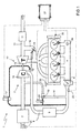
- numeral 1 indicates as a whole an internal combustion engine supercharged by means of a turbocharger supercharging system 2.
- the internal combustion engine 1 comprises four cylinders 3, each of which is connected to an intake manifold 4 by means of at least one respective intake valve (not shown) and to an exhaust manifold 5 by means of at least one respective exhaust valve (not shown).
- the intake manifold 4 receives fresh air (i.e. air coming from the external environment) through an intake pipe 6, which is provided with an air cleaner 7 and is adjusted by a throttle 8.
- An intercooler 9 for cooling the intake air is arranged along the intake pipe 6.
- An exhaust pipe 10, which feeds the exhaust gases produced by combustion to an exhaust system, is connected to the exhaust manifold 5, which exhaust pipe emits the gases produced by the combustion into the atmosphere and normally comprises at least one catalyzer 11 and at least one silencer (not shown) arranged downstream of the catalyzer 11.
- the supercharging system 2 of the internal combustion engine 1 comprises a turbocharger 12 provided with a turbine 13, which is arranged along the exhaust pipe 10 to turn at high speed under the bias of the exhaust gases expelled from the cylinders 3, and a compressor 14, which is arranged along the intake pipe 6 and is mechanically connected to the turbine 13 in order to be rotatably fed by the turbine 13 itself and increase the pressure of the air fed into the intake pipe 6.
- a bypass pipe 15 is arranged along the exhaust pipe 10 and connected in parallel to the turbine 13 so that its ends are connected upstream and downstream of the turbine 13 itself.
- a wastegate valve 16 is arranged along the bypass pipe 15, is adapted to adjust the exhaust gas flow-rate flowing through the bypass pipe 15 and is driven by an actuator 17.
- a bypass pipe 18 is arranged along the exhaust pipe 6 and is connected in parallel to the compressor 14 so that its ends are connected upstream and downstream of the compressor 14 itself.
- a Poff valve 19 is arranged along the bypass pipe 18, adapted to adjust the exhaust gas flow flowing through the bypass pipe 18 and driven by an actuator 20.
- the internal combustion engine 1 is provided with an electric machine mechanically connected to the turbocharger 12 and set up to recover exhaust gas energy; in this variant, it is possible both to deliver the necessary torque by consuming electricity and to brake by delivering electricity.
- control method described above can be applied to a supercharged internal combustion engine of the type described in patent application EP-Al-2096277 , which comprises a turbine, a compressor mechanically independent from the turbine, an electric generator rotatably fed by the turbine for generate electricity and an electric motor which rotatably feeds the compressor.
- each cylinder 3 for each engine cycle may be regulated by means of a respective intake valve (not shown) by means of a valve actuation device with a variable opening law, such as an electromagnetic or electrohydraulic camless actuation device.
- a valve actuation device with variable opening law such as an electromagnetic or electrohydraulic camless actuation device.
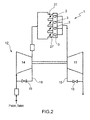
- the mass of air entrapped in each cylinder 3 for each engine cycle is regulated by means of the interposition of a valve 27, preferably a throttle as shown in figure 2 , between the compressor 14 and the intake valves.
- a valve actuation device with variable opening law may be provided and a valve 27, preferably a throttle, may be inserted between the compressor 14 and the intake valves.
- the internal combustion engine 1 is controlled by an electronic control unit 21, which governs the operation of all the components of the internal combustion engine 1, including the supercharging system 2.
- the electronic control unit 21 drives the actuators 17 and 20 of the wastegate valve 16 and of the Poff valve 19.
- the electronic control unit 21 is connected to sensors 22, which measure the temperature T o and the pressure P o along the intake pipe 6 upstream of the compressor 14, to sensors 23, which measure the temperature and pressure along the intake pipe 6 upstream of the throttle 8, and to sensors 24, which measure the temperature and pressure inside the intake manifold 4.
- the electronic control unit 21 is connected to a sensor 25, which measures the angular position (and thus the rotation speed) of a crankshaft of the internal combustion engine 1, and to a sensor 26, which measures the timing of the intake and/or exhaust valves. It is similarly worth noting that no sensors adapted to measure the rotation speed of the turbocharger 12 are needed.
- the electronic control unit 21 is set up to manage a supercharging reserve which allows to optimize the performance of the internal combustion engine 1.
- the control method used by the electronic control unit 21 for managing the supercharging reserve is described below.
- This control method includes maintaining an actual supercharging pressure Pobj (corresponding to the target pressure Pobj for control) higher than the minimum target supercharging pressure Pobj_loaded capable of maintaining the target load, i.e. Ptmin.
- This method may be penalizing from the point of view of fuel consumption, because it may force the engine control to partially close the throttle 8 with consequent reduction of efficiency; in this case, the compression work of the turbocharger 12 is partially wasted, counter-pressure in exhaust increases along with the pumping work of the pistons, with a consequent increase of fuel consumption.
- this control method improves transient performance because the turbocharger 12 is maintained constantly active and is thus capable of starting operation very rapidly (i.e. the supercharging reserve can be used in case of need).
- the turbocharger 12 responds rapidly without appreciable turbo lag when a sudden, rapid request is made in a low torque or power condition (low rpm and slow speed), e.g. when the driver decisively floors the accelerator pedal).
- control method includes determining a minimum supercharging pressure value Pt min and a maximum supercharging pressure value Pt max which guarantee the target load, i.e. the mass of air needed by the engine to generate the desired torque.
- the difference between the maximum supercharging pressure value Pt max and the minimum supercharging value Pt min defines a maximum supercharging reserve RDS max .
- the actual supercharging pressure Pobj which becomes the control target, is kept higher than the minimum target supercharging pressure Ptmin and is equal to a value comprised within the maximum supercharging reserve RDS max .
- an actual supercharging reserve RDS which is equal to the difference between the actual supercharging pressure Pobj and the minimum target supercharging pressure Ptmin needed to guarantee the target load, can be defined.
- the actual supercharging reserve RDS in case of need allows the turbocharger 12 to start operation very rapidly.
- a degree of supercharging reserve GRDS as the ratio between the actual supercharging reserve RDS and the maximum supercharging reserve RDSmax.
- the extent of the actual supercharging reserve RDS may be determined as a function of a plurality of targets. In particular, it is possible to assume to alternatively optimize one of the following targets or a combination thereof:
- the extent of the actual supercharging reserve RDS is variable as a function of a plurality of parameters. Some of these parameters may be determined during a preliminary step of setting up and tuning of the electronic control unit 21, while other parameters may be determined while driving by the car driver.
- the extent of the actual supercharging reserve RDS may be varied as a function of the position of the joystick which determines the operating mode chosen by the driver.
- a "less reactive control” (less or no supercharging reserve RDS) is used when normal operating mode, which privileges reduction of fuel consumption, is selected
- a “more reactive control” higher supercharging reserve RDS
- the driver may choose from a plurality (usually four) of different positions of the joystick to which different supercharging extents correspond, e.g. on Formula 1 cars.
- the extent of the actual supercharging reserve RDS may be varied as a function of the point of the race track and/or of the road where the car is at.
- the supercharging reserve RDS may be determined as a function of the point of the race track in order to guarantee the maximum acceleration after corners, pick up on straights and boost top speed by optimizing the performance-fuel consumption trade-off.
- the electronic control unit 21 is connected to the car navigator so as to acquire the necessary information by means of the navigator maps.
- the point of the race track or road where the car is at may be expressed either as the distance from a predetermined point of a race track (typically, e.g. the arrival line) in case of sports applications or more in general by means of the coordinates (latitude, longitude and altitude) thereof.
- the extent of the actual supercharging reserve RDS is variable as a function of the point of the race track of the race being disputed and the number of laps left to finish the race.
- the extent of the actual supercharging reserve RDS may be varied also as a function of the filling state of the fuel tank.
- the extent of the actual supercharging reserve RDS may be determined as a function of the amount of fuel left in the tank and as a function of the number of laps left in a race being disputed, in case of sports applications.
- the extent of the actual supercharging reserve RDS may be determined as a function of the amount of fuel left in the tank and as a function of the kilometers left to the traveled to reach destination, in the case in which the electronic control unit 21 is connected to the navigator of the car and the driver has previously set a route.
- the extent of the actual supercharging reserve RDS is determined as a function of the residual range desired by the driver of the car.
- the extent of the actual supercharging reserve RDS may be varied as a function of the difference between the maximum deliverable torque Cmax of the internal combustion engine 1 and the actual torque C delivered by the supercharged internal combustion engine 1.
- the actual supercharging reserve RDS tends to zero when the actual torque C delivered by the internal combustion engine 1 tends to the maximum deliverable torque Cmax of the internal combustion engine 1, and vice versa.
- the actual torque C delivered by the internal combustion engine 1 is lower than the maximum deliverable torque Cmax of the internal combustion engine 1 when the car corners; thus, the actual supercharging reserve RDS is different from zero.
- the actual supercharging reserve RDS allows to rapidly deliver the requested torque when the driver decisively floors the accelerator pedal to request more torque to tackle the next straight.
- the actual torque C delivered by the internal combustion engine 1 tends to be equal to the maximum deliverable torque Cmax of the internal combustion engine 1 and thus the actual supercharging reserve RDS tends to zero.
- the actual supercharging reserve RDS may be selectively determined as a function of one of the factors listed above or by a combination of said factors.
- the target supercharging pressure P obj is equal to a pressure value comprised between the minimum supercharging pressure value Pt min and the maximum supercharging pressure value Pt max .
- the target supercharging pressure value Ptobj_csmin capable of minimizing specific fuel consumption C s is a value which may be determined experimentally for all engine points.
- the target supercharging pressure P obj capable of minimizing specific fuel consumption C s is variable as a function of the rotation speed n expressed in revolutions per minute [rpm] and of the load C.
- the load C may, in turn, be determined by the actual delivered torque Ce, by the positive indicated torque Ci+, by the indicated torque Ci or yet again by the intake volumetric efficiency (obtained from the ratio between air mass entrapped in each cylinder 3 for each cycle and the mass of air which fills each cylinder 3 for each cycle in reference conditions).
- the supercharging pressure Ptobj_csmin capable of minimizing the specific fuel consumption of the engine is determined as a function of engine point, load and rotation speed, throttle position (if present), variable valve lift rule, timing and finally EGR position or amount.
- the supercharging reserve RDS capable of minimizing the specific fuel consumption of the engine tends to be canceled out, i.e. the throttle tends to wide open WOT position.
- the minimum supercharging pressure value Pt min and the maximum supercharging pressure value Pt max may be determined as follows.
- the maximum supercharging pressure value Pt max is the maximum permitted supercharging pressure of the turbocharger 12 and/or the pressure value which corresponds to the maximum torque C max delivered by the internal combustion engine 1.
- the maximum supercharging pressure value Pt max is variable as a function of the reduced mass flow rate M R of the compressor 14.
- Pt_max_ass(Mrid) i.e. the maximum achievable pressure
- the internal combustion engine 1 is experimentally determined during a preliminary step of setting up and tuning of the internal combustion engine 1 as a function of the reduced absolute mass flow rate, i.e. in the most favorable ambient conditions (atmospheric pressure and ambient temperature), and a function of the electric machine, in case of turbo compound (law which essentially corresponds to wastegate valve 16 tending to closed compatibly with the structural limits of the turbocharger or 12 or turbo compound).
- the characteristic curves of the compressor 14 (supplied by the manufacturer of the turbocharger 12) on a reduced mass flow rate/compression ratio plane are analyzed during a step of designing and tuning of the internal combustion engine 1.
- the curves which limit the rotation speed of the turbocharger and the pumping of the turbocharger 12 are determined by analyzing the characteristic operation curves of the compressor 14; and the target pressure downstream of the compressor 14 is limited as a function of the aforesaid characteristic curves.
- the maximum supercharging pressure value Pt_max_ass(Mrid) defined above is thus limited by the supercharging pressure value obtained as the product of the limit compression ratio (variable as a function of the reduced mass curve and obtained by analyzing the characteristic curves of the compressor 14) and the pressure value upstream of the compressor 14, which is simply atmospheric pressure minus the respective load losses.
- the limit compression ratio is variable as a function of a dynamic index ⁇ dyn which allows to modify said characteristic operating curves of the compressor 14; said dynamic index ⁇ dyn is determined, according to a preferred variant, as a function of the reduced mass flow rate of the compressor 14 and of the reduced mass flow rate dynamics of the compressor 14.
- Ptmax Mrid RRCOMPLIM Mrid + ⁇ ⁇ dyn Mdyn ⁇ Mrid * Pupst ream_of_compressor
- the minimum supercharging pressure Pt min is the minimum supercharging pressure which allows to achieve the desired actual engine torque; essentially, Pt min is the minimum pressure which guarantees the entrapped air mass necessary to supply the desired torque to the drive shaft, taking into account friction, pumping work and auxiliary loads (air conditioner, rear window wiper etc.) and all engine parameters (spark advance, mixture titration, actuator position etc.).
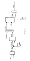
- Figure 3 shows a possible control model which supplies Ptmin starting from the torque request.
- the request of actual torque Ce_obj (to drive shaft) by the driver is determined by the position of the accelerator pedal Ped, e.g. by means of a map.
- Engine friction requests, pumping working Pomp and auxiliary loads Aux must be taken into consideration in addition to the request for actual torque Ce_obj.
- the average positive indicated torque Ci_obj is determined in this manner.
- a map, which supplies the necessary air mass m' obj , as a function of the average positive indicated torque Ci_obj and the engine speed n, is thus used. Such a map is the inverse of the specific fuel consumption Cs.
- the necessary air mass m' obj thus obtained is saturated to a maximum air mass value m max (n), which is, in turn, determined by the maximum torque and is variable as a function of the engine speed n.
- the necessary pressure Pt'obj upstream of the intake valve may be determined by means of the filling model from the obtained actual air mass m obj ; such a pressure Pt'obj minus load losses is the minimum pressure needed in the supercharging circuit, which saturates at atmospheric pressure, and supplies the minimum target supercharging pressure Ptmin.
- the supercharging reserve RDS may be such to reduce specific fuel consumption in case in which the lift law of the variable intake valve leads to a reduction of pumping work.
- the supercharging reserve RDS may allow to deliver the same torque with a higher minimum target supercharging pressure Ptmin, and consequently specific fuel consumption C s is reduced and reactivity is achieved in case of request for torque increase and/or acceleration by virtue of the supercharging reserve, the delivered torque being equal.
- the variable lift law actuator which controls the intake valve may be, for instance, of the camless electromagnetic type (which allows any timing) or hydroelectric (which allows any type of lift, and consequently maximum lift and timing).
- the electronic control unit 21 determines the target torque C i_obj when the car driver requests torque C by flooring the accelerator pedal.
- target torque C i_obj corresponds to a target air mass to be entrapped in the cylinders 3 which must be saturated at a maximum target air mass value variable as a function of the rotation speed N expressed in revolutions per minute [rpm], to which the maximum engine torque is associated.
- the electronic control unit 21 makes a target pressure Ptobj' in the intake manifold 4, which saturates at atmospheric pressure and supplies (minus load losses) the minimum target supercharging pressure Ptmin, correspond to the target air mass.
- the supercharging reserve RDS may be determined with the aim of optimizing an additional parameter.
- the supercharging reserve RDS may be determined to optimize the efficiency ⁇ turbo of the turbocharger 12.
- the efficiency ⁇ turbo of the turbocharger 12 is obtained as the product of the efficiency ⁇ t of the turbocharger 13, of the efficiency ⁇ c of the compressor 14 and of organic efficiency ⁇ o .
- the efficiency ⁇ c of the compressor 14 is variable as a function of the supercharging ratio and of the reduced mass flow rate of the compressor 14, while the efficiency ⁇ t of the turbine 13 is variable as a function of the expansion ratio and of the mass flow rate of the turbine 13. In this manner, the increase of specific fuel consumption Cs can be limited and at the same time it is possible to benefit from the dynamic advantage deriving from the supercharging reserve RDS.
- the target supercharging pressure P obj is equal to the pressure P etactmax which allows to optimize the efficiency ⁇ turbo of the turbocharger 12.
- the supercharging reserve RDS may be determined with the aim of optimizing a further parameter.
- the supercharging reserve RDS may be determined in order to optimize the overall efficiency of the turbocharger 12 and of a possible electric machine connected thereto for recovering energy. This variant may be advantageously applied, in particular to comply with new F1 regulations.
- the target supercharging pressure P obj is equal to the pressure P etatcelmax which allows to optimize overall efficiency of the turbocharger 12 and of the electric machine connected to the turbocharger 12 for recovering energy and/or accelerating the rotor.
- a plurality of electric machines may be inserted.
- the rotation speed of the turbo machine 12, and consequently of the possible mechanically connected electric machine, is associated to the supercharging pressure and the reduced mass flow rate, while efficiency is associated to the rotation speed of the turbo machine 12 and the electric load.
- x c means the position of the car along the Grand Prix race track; the position of the car is typically expressed as the distance from the arrival line.
- joystick instead means the joystick position selected by the car driver.
- the joystick positions to choose from are, for instance, four, indicated by increasing numbers/digits. It is worth noting that the extent of the supercharging reserve RDS increases, and consequently so does fuel consumption, as the selected joystick position increases. Consequently, for example, position 3 of the joystick corresponds to a more extensive supercharging reserve RDS and higher fuel consumption than that which corresponds to position 1 of the joystick.
- Nrace_left indicates the number of laps left to finish the Grand Prix race.
- Joystick_lim means instead the joystick position which corresponds to the maximum residual supercharging reserve RDS allowing the car to finish the race.
- Function f 2 is the inverse fuel consumption function per each lap of the Grand Prix race as a function of the selected joystick position, i.e. the mapping of the degree of supercharging reserve GRDS at the position on the race track.
- this function is represented by a vector in which a mapping of the supercharging reserve, and consequently of a fuel consumption per lap with such a degree of supercharging reserve GRDS corresponds to each selectable joystick position.
- Joystick_sat means instead the joystick position which corresponds to the supercharging reserve selected by the driver (by selecting the joystick position) which is saturated to the value of the supercharging reserve allowing the car to finish the Grand Prix race (and calculated by means of joystick_lim).
- Function f 1 is a function of the difference between the maximum delivered torque C max and the delivered torque C.
- the value of the function f1 reduces the extent of the supercharging reserve the more the torque C approaches the maximum deliverable torque C max .
- Function f 0 is a function, typically represented by a map, which defines the supercharging reserve RDS for each position of the car along the Grand Prix race track and for each selectable position of the joystick; i.e. several mappings of the degree of supercharging reserve GRDS for position on the race track may be defined as a function of the joystick position. As previously explained, the extent of the degree of supercharging reserve GRDS is higher at the higher joystick positions. The trade-off between performance and fuel consumption is implicit in the function f 0 (xc,joystick).
- the car's performance can be boosted to the maximum (and consequently the extent of the supercharging reserve RDS can be increased) to the detriment of fuel consumption of the car.
- joystick_sat can be determined in a different manner.
- the selected joystick position is different from the maximum selectable position (e.g. the position indicated by "4"), i.e. that to which the maximum extent of the supercharging reserve RDS corresponds, then joystick_sat is determined as explained above, i.e. as the supercharging reserve selected by the driver (by selecting the joystick position) which is saturated to the value of the supercharging reserve allowing the car to finish the Grand Prix race (and calculated by means of joystick_lim) .
- joystick_sat is determined differently as a function of the value assigned to the joystick_lim variable. In the case in which the joystick_lim is equal to 1, then the joystick_sat is also equal to 1. Instead, in the case in which the joystick_lim is higher than 1, then the joystick_sat is equal to the joystick variable decreased by 1.
- joystick_sat is the supercharging reserve selected by the driver allowing the car to finish the Grand Prix race at the same time, it is important to maintain a supercharging reserve of modest extent available to allow the car to finish the Grand Prix race if joystick_lim is equal to 1 (i.e. to the position which corresponds to the minimum extent of supercharging reserve). In the case in which joystick_lim is other than 1 (i.e. in the position which corresponds to the minimum extent supercharging reserve) the increase the extent of the supercharging reserve may be increased instead for a limited period of time.
- this condition may occur in the case in which the driver selects joystick position 4 to allow the car to overtake on a straight or to run a lap pushing the car to the limit of its performance.
- the average supercharging reserve RDS during the remaining laps of the race will be compromised but it will be possible to finish the Grand Prix race in all cases.
- the method for controlling the supercharged internal combustion engine 1 described above has many advantages.
- control method described above is simple and cost-effective to implement in an electronic control unit of an internal combustion engine 1 because it requires neither hardware modifications nor high calculation capacity nor high memory storage capacity.
- control method described above allows to always obtain a very rapid response in any operating modes of a supercharged internal combustion engine 1 because the supercharging air circuit is already pressurized and the turbocharger 12 already has a higher speed to respond to the requests for more drive torque C.
- control method described above allows to vary the response of the turbocharger 12 as a function of a plurality of parameters and as a function of the desires of the driver and at the same allows to optimize the trade-off between fuel consumption and performance.
Landscapes
- Engineering & Computer Science (AREA)
- Chemical & Material Sciences (AREA)
- Combustion & Propulsion (AREA)
- Mechanical Engineering (AREA)
- General Engineering & Computer Science (AREA)
- Supercharger (AREA)
Applications Claiming Priority (1)
| Application Number | Priority Date | Filing Date | Title |
|---|---|---|---|
| IT000400A ITBO20110400A1 (it) | 2011-07-05 | 2011-07-05 | Metodo di controllo della velocita' di un motore a combustione interna sovralimentato |
Publications (4)
| Publication Number | Publication Date |
|---|---|
| EP2543856A2 true EP2543856A2 (de) | 2013-01-09 |
| EP2543856A8 EP2543856A8 (de) | 2013-04-17 |
| EP2543856A3 EP2543856A3 (de) | 2013-08-21 |
| EP2543856B1 EP2543856B1 (de) | 2018-06-20 |
Family
ID=44898485
Family Applications (1)
| Application Number | Title | Priority Date | Filing Date |
|---|---|---|---|
| EP12175211.7A Active EP2543856B1 (de) | 2011-07-05 | 2012-07-05 | Verfahren zur Steuerung eines aufgeladenen Verbrennungsmotors |
Country Status (2)
| Country | Link |
|---|---|
| EP (1) | EP2543856B1 (de) |
| IT (1) | ITBO20110400A1 (de) |
Cited By (1)
| Publication number | Priority date | Publication date | Assignee | Title |
|---|---|---|---|---|
| EP3006702A1 (de) * | 2014-10-09 | 2016-04-13 | Toyota Jidosha Kabushiki Kaisha | Verbrennungsmotor und steuerungsverfahren dafür |
Citations (3)
| Publication number | Priority date | Publication date | Assignee | Title |
|---|---|---|---|---|
| EP2096277A1 (de) | 2008-02-27 | 2009-09-02 | MAGNETI MARELLI POWERTRAIN S.p.A. | Aufgeladene Brennkraftmaschine |
| EP1741895B1 (de) | 2005-07-05 | 2010-03-03 | Magneti Marelli S.p.A. | Methode und Vorrichtung zur Drehzahl-Regelung eines Turboladers einer Brennkraftmaschine |
| EP2014894B1 (de) | 2007-07-09 | 2010-10-13 | Magneti Marelli S.p.A. | Verfahren zur Steuerung einer durch einen Turbolader aufgeladenen Brennkraftmaschine |
Family Cites Families (6)
| Publication number | Priority date | Publication date | Assignee | Title |
|---|---|---|---|---|
| US6161384A (en) * | 1994-05-02 | 2000-12-19 | Waukesha Engine Division, Dresser Equipment Group, Inc. | Turbocharger control management system throttle reserve control |
| DE19817885A1 (de) * | 1998-04-22 | 1999-10-28 | Bosch Gmbh Robert | Anordnung zum Wiederaufbauen des Drehmoments einer aufgeladenen Brennkraftmaschine nach einem ASR-Eingriff |
| LU90867B1 (en) * | 2001-12-21 | 2003-06-24 | Delphi Tech Inc | Method for controlling the boost pressure of a turbocharged internal combustion engine |
| US6672060B1 (en) * | 2002-07-30 | 2004-01-06 | Ford Global Technologies, Llc | Coordinated control of electronic throttle and variable geometry turbocharger in boosted stoichiometric spark ignition engines |
| US6779344B2 (en) * | 2002-12-20 | 2004-08-24 | Deere & Company | Control system and method for turbocharged throttled engine |
| FR2854658B1 (fr) * | 2003-05-06 | 2007-02-09 | Siemens Vdo Automotive | Procede de gestion du debit d'air dans un moteur a combustion interne et dispositif correspondant |
-
2011
- 2011-07-05 IT IT000400A patent/ITBO20110400A1/it unknown
-
2012
- 2012-07-05 EP EP12175211.7A patent/EP2543856B1/de active Active
Patent Citations (3)
| Publication number | Priority date | Publication date | Assignee | Title |
|---|---|---|---|---|
| EP1741895B1 (de) | 2005-07-05 | 2010-03-03 | Magneti Marelli S.p.A. | Methode und Vorrichtung zur Drehzahl-Regelung eines Turboladers einer Brennkraftmaschine |
| EP2014894B1 (de) | 2007-07-09 | 2010-10-13 | Magneti Marelli S.p.A. | Verfahren zur Steuerung einer durch einen Turbolader aufgeladenen Brennkraftmaschine |
| EP2096277A1 (de) | 2008-02-27 | 2009-09-02 | MAGNETI MARELLI POWERTRAIN S.p.A. | Aufgeladene Brennkraftmaschine |
Cited By (1)
| Publication number | Priority date | Publication date | Assignee | Title |
|---|---|---|---|---|
| EP3006702A1 (de) * | 2014-10-09 | 2016-04-13 | Toyota Jidosha Kabushiki Kaisha | Verbrennungsmotor und steuerungsverfahren dafür |
Also Published As
| Publication number | Publication date |
|---|---|
| EP2543856A8 (de) | 2013-04-17 |
| EP2543856B1 (de) | 2018-06-20 |
| EP2543856A3 (de) | 2013-08-21 |
| ITBO20110400A1 (it) | 2013-01-06 |
Similar Documents
| Publication | Publication Date | Title |
|---|---|---|
| US10018127B2 (en) | Method and device for adjusting a volumetric efficiency and a charge density in an internal combustion engine | |
| US7805939B2 (en) | Controller for internal combustion engine with supercharger | |
| JP4378700B2 (ja) | 過給機付き内燃機関の制御装置 | |
| US6971367B2 (en) | Fuel control system and method of engine | |
| US7236874B2 (en) | Torque control apparatus and vehicle control system having the same | |
| US9297317B2 (en) | Method for controlling an internal combustion engine | |
| US6758198B1 (en) | Method for controlling an internal combustion engine with nitrous oxide injection | |
| US6704639B2 (en) | Method of calculating engine torque | |
| JP2000073800A (ja) | 電磁駆動式吸排気バルブを備えたエンジンの制御装置 | |
| CN101498247A (zh) | 基于转矩系统中的速度控制 | |
| EP1860010A1 (de) | Motorsteuerung mit Luftdruckkorrekturfunktion | |
| JP2005220775A (ja) | エンジン制御装置 | |
| US20150159546A1 (en) | Control device of internal combustion engine equipped with turbo supercharger | |
| EP1065117A2 (de) | Unterdruckregelungsapparat für eine Brennkraftmaschine in einem Fahrzeug | |
| EP2674599B1 (de) | Verfahren zur Steuerung eines Verbrennungsmotors | |
| US20050010335A1 (en) | Method for operating a motor vehicle | |
| US9334814B2 (en) | Method for controlling an internal combustion engine | |
| EP2543856B1 (de) | Verfahren zur Steuerung eines aufgeladenen Verbrennungsmotors | |
| US6539914B1 (en) | Internal combustion engine, a control element for the internal combustion engine, and method for operating the internal combustion engine | |
| JP6763488B2 (ja) | 車両用内燃機関の制御方法および制御装置 | |
| US9399399B2 (en) | Method for controlling an internal combustion engine | |
| JP2007263127A (ja) | エンジンの燃料制御装置,エンジンの燃料制御方法 | |
| JP2004526096A (ja) | 内燃機関の運転方法及びその運転制御装置 | |
| JP2006046297A (ja) | ハイブリッド車の制御装置 | |
| JP2001263104A (ja) | 可変動弁の制御装置 |
Legal Events
| Date | Code | Title | Description |
|---|---|---|---|
| PUAI | Public reference made under article 153(3) epc to a published international application that has entered the european phase |
Free format text: ORIGINAL CODE: 0009012 |
|
| AK | Designated contracting states |
Kind code of ref document: A2 Designated state(s): AL AT BE BG CH CY CZ DE DK EE ES FI FR GB GR HR HU IE IS IT LI LT LU LV MC MK MT NL NO PL PT RO RS SE SI SK SM TR |
|
| AX | Request for extension of the european patent |
Extension state: BA ME |
|
| RIN1 | Information on inventor provided before grant (corrected) |
Inventor name: PANCIROLI, MARCO |
|
| PUAL | Search report despatched |
Free format text: ORIGINAL CODE: 0009013 |
|
| AK | Designated contracting states |
Kind code of ref document: A3 Designated state(s): AL AT BE BG CH CY CZ DE DK EE ES FI FR GB GR HR HU IE IS IT LI LT LU LV MC MK MT NL NO PL PT RO RS SE SI SK SM TR |
|
| AX | Request for extension of the european patent |
Extension state: BA ME |
|
| RIC1 | Information provided on ipc code assigned before grant |
Ipc: F02B 39/16 20060101ALI20130712BHEP Ipc: F02D 41/02 20060101ALI20130712BHEP Ipc: F02D 41/00 20060101AFI20130712BHEP |
|
| 17P | Request for examination filed |
Effective date: 20140221 |
|
| GRAP | Despatch of communication of intention to grant a patent |
Free format text: ORIGINAL CODE: EPIDOSNIGR1 |
|
| INTG | Intention to grant announced |
Effective date: 20171120 |
|
| GRAS | Grant fee paid |
Free format text: ORIGINAL CODE: EPIDOSNIGR3 |
|
| GRAJ | Information related to disapproval of communication of intention to grant by the applicant or resumption of examination proceedings by the epo deleted |
Free format text: ORIGINAL CODE: EPIDOSDIGR1 |
|
| GRAL | Information related to payment of fee for publishing/printing deleted |
Free format text: ORIGINAL CODE: EPIDOSDIGR3 |
|
| INTC | Intention to grant announced (deleted) | ||
| GRAR | Information related to intention to grant a patent recorded |
Free format text: ORIGINAL CODE: EPIDOSNIGR71 |
|
| GRAA | (expected) grant |
Free format text: ORIGINAL CODE: 0009210 |
|
| AK | Designated contracting states |
Kind code of ref document: B1 Designated state(s): AL AT BE BG CH CY CZ DE DK EE ES FI FR GB GR HR HU IE IS IT LI LT LU LV MC MK MT NL NO PL PT RO RS SE SI SK SM TR |
|
| INTG | Intention to grant announced |
Effective date: 20180516 |
|
| REG | Reference to a national code |
Ref country code: GB Ref legal event code: FG4D |
|
| REG | Reference to a national code |
Ref country code: IE Ref legal event code: FG4D |
|
| REG | Reference to a national code |
Ref country code: AT Ref legal event code: REF Ref document number: 1010764 Country of ref document: AT Kind code of ref document: T Effective date: 20180715 |
|
| REG | Reference to a national code |
Ref country code: DE Ref legal event code: R096 Ref document number: 602012047604 Country of ref document: DE |
|
| REG | Reference to a national code |
Ref country code: FR Ref legal event code: PLFP Year of fee payment: 7 |
|
| REG | Reference to a national code |
Ref country code: NL Ref legal event code: MP Effective date: 20180620 |
|
| PG25 | Lapsed in a contracting state [announced via postgrant information from national office to epo] |
Ref country code: BG Free format text: LAPSE BECAUSE OF FAILURE TO SUBMIT A TRANSLATION OF THE DESCRIPTION OR TO PAY THE FEE WITHIN THE PRESCRIBED TIME-LIMIT Effective date: 20180920 Ref country code: NO Free format text: LAPSE BECAUSE OF FAILURE TO SUBMIT A TRANSLATION OF THE DESCRIPTION OR TO PAY THE FEE WITHIN THE PRESCRIBED TIME-LIMIT Effective date: 20180920 Ref country code: FI Free format text: LAPSE BECAUSE OF FAILURE TO SUBMIT A TRANSLATION OF THE DESCRIPTION OR TO PAY THE FEE WITHIN THE PRESCRIBED TIME-LIMIT Effective date: 20180620 Ref country code: SE Free format text: LAPSE BECAUSE OF FAILURE TO SUBMIT A TRANSLATION OF THE DESCRIPTION OR TO PAY THE FEE WITHIN THE PRESCRIBED TIME-LIMIT Effective date: 20180620 Ref country code: LT Free format text: LAPSE BECAUSE OF FAILURE TO SUBMIT A TRANSLATION OF THE DESCRIPTION OR TO PAY THE FEE WITHIN THE PRESCRIBED TIME-LIMIT Effective date: 20180620 |
|
| REG | Reference to a national code |
Ref country code: LT Ref legal event code: MG4D |
|
| PG25 | Lapsed in a contracting state [announced via postgrant information from national office to epo] |
Ref country code: RS Free format text: LAPSE BECAUSE OF FAILURE TO SUBMIT A TRANSLATION OF THE DESCRIPTION OR TO PAY THE FEE WITHIN THE PRESCRIBED TIME-LIMIT Effective date: 20180620 Ref country code: LV Free format text: LAPSE BECAUSE OF FAILURE TO SUBMIT A TRANSLATION OF THE DESCRIPTION OR TO PAY THE FEE WITHIN THE PRESCRIBED TIME-LIMIT Effective date: 20180620 Ref country code: HR Free format text: LAPSE BECAUSE OF FAILURE TO SUBMIT A TRANSLATION OF THE DESCRIPTION OR TO PAY THE FEE WITHIN THE PRESCRIBED TIME-LIMIT Effective date: 20180620 Ref country code: GR Free format text: LAPSE BECAUSE OF FAILURE TO SUBMIT A TRANSLATION OF THE DESCRIPTION OR TO PAY THE FEE WITHIN THE PRESCRIBED TIME-LIMIT Effective date: 20180921 |
|
| REG | Reference to a national code |
Ref country code: AT Ref legal event code: MK05 Ref document number: 1010764 Country of ref document: AT Kind code of ref document: T Effective date: 20180620 |
|
| PG25 | Lapsed in a contracting state [announced via postgrant information from national office to epo] |
Ref country code: NL Free format text: LAPSE BECAUSE OF FAILURE TO SUBMIT A TRANSLATION OF THE DESCRIPTION OR TO PAY THE FEE WITHIN THE PRESCRIBED TIME-LIMIT Effective date: 20180620 |
|
| PG25 | Lapsed in a contracting state [announced via postgrant information from national office to epo] |
Ref country code: AT Free format text: LAPSE BECAUSE OF FAILURE TO SUBMIT A TRANSLATION OF THE DESCRIPTION OR TO PAY THE FEE WITHIN THE PRESCRIBED TIME-LIMIT Effective date: 20180620 Ref country code: IS Free format text: LAPSE BECAUSE OF FAILURE TO SUBMIT A TRANSLATION OF THE DESCRIPTION OR TO PAY THE FEE WITHIN THE PRESCRIBED TIME-LIMIT Effective date: 20181020 Ref country code: CZ Free format text: LAPSE BECAUSE OF FAILURE TO SUBMIT A TRANSLATION OF THE DESCRIPTION OR TO PAY THE FEE WITHIN THE PRESCRIBED TIME-LIMIT Effective date: 20180620 Ref country code: RO Free format text: LAPSE BECAUSE OF FAILURE TO SUBMIT A TRANSLATION OF THE DESCRIPTION OR TO PAY THE FEE WITHIN THE PRESCRIBED TIME-LIMIT Effective date: 20180620 Ref country code: EE Free format text: LAPSE BECAUSE OF FAILURE TO SUBMIT A TRANSLATION OF THE DESCRIPTION OR TO PAY THE FEE WITHIN THE PRESCRIBED TIME-LIMIT Effective date: 20180620 Ref country code: PL Free format text: LAPSE BECAUSE OF FAILURE TO SUBMIT A TRANSLATION OF THE DESCRIPTION OR TO PAY THE FEE WITHIN THE PRESCRIBED TIME-LIMIT Effective date: 20180620 Ref country code: SK Free format text: LAPSE BECAUSE OF FAILURE TO SUBMIT A TRANSLATION OF THE DESCRIPTION OR TO PAY THE FEE WITHIN THE PRESCRIBED TIME-LIMIT Effective date: 20180620 |
|
| PG25 | Lapsed in a contracting state [announced via postgrant information from national office to epo] |
Ref country code: SM Free format text: LAPSE BECAUSE OF FAILURE TO SUBMIT A TRANSLATION OF THE DESCRIPTION OR TO PAY THE FEE WITHIN THE PRESCRIBED TIME-LIMIT Effective date: 20180620 Ref country code: ES Free format text: LAPSE BECAUSE OF FAILURE TO SUBMIT A TRANSLATION OF THE DESCRIPTION OR TO PAY THE FEE WITHIN THE PRESCRIBED TIME-LIMIT Effective date: 20180620 |
|
| REG | Reference to a national code |
Ref country code: CH Ref legal event code: PL |
|
| REG | Reference to a national code |
Ref country code: DE Ref legal event code: R097 Ref document number: 602012047604 Country of ref document: DE |
|
| PG25 | Lapsed in a contracting state [announced via postgrant information from national office to epo] |
Ref country code: LU Free format text: LAPSE BECAUSE OF NON-PAYMENT OF DUE FEES Effective date: 20180705 Ref country code: MC Free format text: LAPSE BECAUSE OF FAILURE TO SUBMIT A TRANSLATION OF THE DESCRIPTION OR TO PAY THE FEE WITHIN THE PRESCRIBED TIME-LIMIT Effective date: 20180620 |
|
| REG | Reference to a national code |
Ref country code: BE Ref legal event code: MM Effective date: 20180731 |
|
| REG | Reference to a national code |
Ref country code: IE Ref legal event code: MM4A |
|
| PLBE | No opposition filed within time limit |
Free format text: ORIGINAL CODE: 0009261 |
|
| STAA | Information on the status of an ep patent application or granted ep patent |
Free format text: STATUS: NO OPPOSITION FILED WITHIN TIME LIMIT |
|
| PG25 | Lapsed in a contracting state [announced via postgrant information from national office to epo] |
Ref country code: IE Free format text: LAPSE BECAUSE OF NON-PAYMENT OF DUE FEES Effective date: 20180705 Ref country code: CH Free format text: LAPSE BECAUSE OF NON-PAYMENT OF DUE FEES Effective date: 20180731 Ref country code: LI Free format text: LAPSE BECAUSE OF NON-PAYMENT OF DUE FEES Effective date: 20180731 |
|
| GBPC | Gb: european patent ceased through non-payment of renewal fee |
Effective date: 20180920 |
|
| 26N | No opposition filed |
Effective date: 20190321 |
|
| PG25 | Lapsed in a contracting state [announced via postgrant information from national office to epo] |
Ref country code: DK Free format text: LAPSE BECAUSE OF FAILURE TO SUBMIT A TRANSLATION OF THE DESCRIPTION OR TO PAY THE FEE WITHIN THE PRESCRIBED TIME-LIMIT Effective date: 20180620 Ref country code: BE Free format text: LAPSE BECAUSE OF NON-PAYMENT OF DUE FEES Effective date: 20180731 |
|
| PG25 | Lapsed in a contracting state [announced via postgrant information from national office to epo] |
Ref country code: SI Free format text: LAPSE BECAUSE OF FAILURE TO SUBMIT A TRANSLATION OF THE DESCRIPTION OR TO PAY THE FEE WITHIN THE PRESCRIBED TIME-LIMIT Effective date: 20180620 |
|
| PG25 | Lapsed in a contracting state [announced via postgrant information from national office to epo] |
Ref country code: GB Free format text: LAPSE BECAUSE OF NON-PAYMENT OF DUE FEES Effective date: 20180920 |
|
| PG25 | Lapsed in a contracting state [announced via postgrant information from national office to epo] |
Ref country code: AL Free format text: LAPSE BECAUSE OF FAILURE TO SUBMIT A TRANSLATION OF THE DESCRIPTION OR TO PAY THE FEE WITHIN THE PRESCRIBED TIME-LIMIT Effective date: 20180620 |
|
| PG25 | Lapsed in a contracting state [announced via postgrant information from national office to epo] |
Ref country code: MT Free format text: LAPSE BECAUSE OF NON-PAYMENT OF DUE FEES Effective date: 20180705 |
|
| PG25 | Lapsed in a contracting state [announced via postgrant information from national office to epo] |
Ref country code: TR Free format text: LAPSE BECAUSE OF FAILURE TO SUBMIT A TRANSLATION OF THE DESCRIPTION OR TO PAY THE FEE WITHIN THE PRESCRIBED TIME-LIMIT Effective date: 20180620 |
|
| PG25 | Lapsed in a contracting state [announced via postgrant information from national office to epo] |
Ref country code: PT Free format text: LAPSE BECAUSE OF FAILURE TO SUBMIT A TRANSLATION OF THE DESCRIPTION OR TO PAY THE FEE WITHIN THE PRESCRIBED TIME-LIMIT Effective date: 20180620 Ref country code: HU Free format text: LAPSE BECAUSE OF FAILURE TO SUBMIT A TRANSLATION OF THE DESCRIPTION OR TO PAY THE FEE WITHIN THE PRESCRIBED TIME-LIMIT; INVALID AB INITIO Effective date: 20120705 |
|
| PG25 | Lapsed in a contracting state [announced via postgrant information from national office to epo] |
Ref country code: MK Free format text: LAPSE BECAUSE OF NON-PAYMENT OF DUE FEES Effective date: 20180620 Ref country code: CY Free format text: LAPSE BECAUSE OF FAILURE TO SUBMIT A TRANSLATION OF THE DESCRIPTION OR TO PAY THE FEE WITHIN THE PRESCRIBED TIME-LIMIT Effective date: 20180620 |
|
| PGFP | Annual fee paid to national office [announced via postgrant information from national office to epo] |
Ref country code: IT Payment date: 20230620 Year of fee payment: 12 |
|
| PGFP | Annual fee paid to national office [announced via postgrant information from national office to epo] |
Ref country code: DE Payment date: 20230620 Year of fee payment: 12 |
|
| PGFP | Annual fee paid to national office [announced via postgrant information from national office to epo] |
Ref country code: FR Payment date: 20240619 Year of fee payment: 13 |