EP2543843A2 - Verfahren zur Einstellung eines Ladedrucks einer Verbrennungskraftmaschine - Google Patents
Verfahren zur Einstellung eines Ladedrucks einer Verbrennungskraftmaschine Download PDFInfo
- Publication number
- EP2543843A2 EP2543843A2 EP12166761A EP12166761A EP2543843A2 EP 2543843 A2 EP2543843 A2 EP 2543843A2 EP 12166761 A EP12166761 A EP 12166761A EP 12166761 A EP12166761 A EP 12166761A EP 2543843 A2 EP2543843 A2 EP 2543843A2
- Authority
- EP
- European Patent Office
- Prior art keywords
- engine
- channel
- internal combustion
- combustion engine
- speed
- Prior art date
- Legal status (The legal status is an assumption and is not a legal conclusion. Google has not performed a legal analysis and makes no representation as to the accuracy of the status listed.)
- Granted
Links
Images

Classifications
-
- F—MECHANICAL ENGINEERING; LIGHTING; HEATING; WEAPONS; BLASTING
- F02—COMBUSTION ENGINES; HOT-GAS OR COMBUSTION-PRODUCT ENGINE PLANTS
- F02B—INTERNAL-COMBUSTION PISTON ENGINES; COMBUSTION ENGINES IN GENERAL
- F02B33/00—Engines characterised by provision of pumps for charging or scavenging
- F02B33/32—Engines with pumps other than of reciprocating-piston type
- F02B33/42—Engines with pumps other than of reciprocating-piston type with driven apparatus for immediate conversion of combustion gas pressure into pressure of fresh charge, e.g. with cell-type pressure exchangers
-
- F—MECHANICAL ENGINEERING; LIGHTING; HEATING; WEAPONS; BLASTING
- F04—POSITIVE - DISPLACEMENT MACHINES FOR LIQUIDS; PUMPS FOR LIQUIDS OR ELASTIC FLUIDS
- F04F—PUMPING OF FLUID BY DIRECT CONTACT OF ANOTHER FLUID OR BY USING INERTIA OF FLUID TO BE PUMPED; SIPHONS
- F04F13/00—Pressure exchangers
Definitions
- the present invention relates to a method for adjusting a boost pressure of an internal combustion engine according to the features in the preamble of patent claim 1.
- a method for operating an internal combustion engine in which fresh air is compressed by a pressure wave supercharger, wherein at least one operating parameter of the pressure wave supercharger, depending on at least one actual operating variable of the internal combustion engine is controlled or regulated.
- the method disclosed therein means a departure from the previous rigid and essentially uncontrolled or uncontrolled operating concepts of pressure wave loaders.
- a pressure wave supercharger arrangement wherein an inflow to a gas pocket is branched off from an exhaust gas supply channel and this inflow is controlled in dependence of the boost pressure via a gas pocket valve.
- the gas pocket valve itself is controlled via a control line.
- the gas pocket inflow is thereby realized by avoiding gas blow-off from the high-pressure duct into the atmosphere at standstill and in emergency operation of the internal combustion engine by opening the gas pocket inflow by means of spring means.
- a pressure wave supercharger arrangement is known in which a rotatable cold gas housing is arranged to improve the performance of the pressure wave supercharger and the internal combustion engine to each other.
- the rotatable cold gas housing is adjusted during operation of the pressure wave supercharger to improve the operation of the pressure wave supercharger over the entire map range of the internal combustion engine.
- thermodynamic state variables Due to the pressure differences between the intake tract and the exhaust gas tract, a gas-dynamic process is formed in the rotor cells of the pressure wave supercharger itself, which produces a virtually infinite number of thermodynamic state variables. Since these are often only calculable through very long and very complex numerical equations, a detailed modeling of a pressure wave loader, which could be implemented on a control unit, is not possible with today's CAE methods.
- Object of the present invention is therefore to provide a method for controlling and regulating a pressure wave supercharger, which optimizes the emission behavior, the response, the durability and the efficiency of a pressure wave supercharger for an internal combustion engine while allowing a largely independent of external influences series use.
- the inventive method for adjusting a boost pressure of an internal combustion engine wherein the boost pressure is constructed by a pressure wave supercharger having a cell rotor and a cell rotor housing and the pressure wave supercharger a channel 1 for sucking fresh air, a channel 2 for discharging the compressed fresh air, a channel. 3 for supplying exhaust gas and a channel 4 for discharging exhaust gas are connected and the pressure wave supercharger has a cold gas housing, are connected to the channel 1 and 2, and a gas pocket valve, which is arranged in the region of the channel 3, characterized by, a position of the actuating element is set and / or regulated as a function of a difference between the actual value and the nominal value of the gas pocket valve position.
- the adjusting element is a rotatable housing, an adjusting element, an edge slider or a control roller which variably change the inlet and outlet openings via a geometric offset of channel 3 and channel 4 to channel 1 and channel 2 can.
- the adjusting element is arranged in the context of the invention on the cold gas side of the pressure wave supercharger. However, it can also be arranged on the hot gas side.
- the gas pocket valve which is arranged in the region of channel 3, further comprises a blow-by valve which regulates the gas flow rate in a channel 3 '.
- the channel 3 ' adjacent to channel 3 and also leads directly into the rotor cell of the cell rotor. Via the gas pocket valve, a variable opening from 0 to 100% of the channel 3 'is possible.
- the gas pocket valve can also form a direct bypass between channel 3 and channel 4 in the context of the invention. Also can be variably controlled via the gas pocket valve then the opening of the bypass from channel 3 to channel 4.
- the method according to the invention therefore offers a solution for optimum, dynamic adjustment of the engine operating state on the basis of energy changes which are present in channel 3.
- a regulation and control of the boost pressure setpoint takes place via the gas pocket valve position.
- the change in position of the gas pocket valve generates an energy pulse in the channel 3 of the pressure wave supercharger.
- This energy change affects the cells of the cell rotor and thus the fresh air to be compressed or compressed.
- the adjusting element is adjusted with a correction value as a function of the change in position of the gas pocket valve.
- the relative value of the difference of the gas pocket valve position is evaluated as a controlled variable and a correction value is displayed as a relative value as a control signal.
- the engine speed of the internal combustion engine is another important preferred input variable, the engine speed of the internal combustion engine.
- a limitation of the current position of the control element is important. This is preferably determined within the scope of the invention by a map structure of actual boost pressure actual value and the engine speed of the internal combustion engine having a maximum value and a minimum value. Between the maximum value and the minimum value, an optimal position of the actuating element or a correction adjustment of the actuating element is determined on the basis of the difference between the gas pocket valve position and the engine speed of the internal combustion engine.
- the inventive dynamic boost pressure control can take place either open-loop or closed-loop. Overall, this can be a significantly faster control behavior and thus response at at the same time achieve low hardware and software costs for control and regulation.
- the relative adjustment of the gas pocket valve is the difference of the adjustment measured over time or the relative adjustment between actual value of the gas pocket valve and target value, which can be determined from a map.
- the optimal position of the gas pocket valve is the optimal position for achieving the highest possible efficiency in the interaction of internal combustion engine and pressure wave loader.
- the difference or the relative adjustment of the gas pocket valve in comparison to the determined or calculated optimum position is a value which shows how optimally the pressure wave process works.
- the Retativwert can therefore be taken as a control variable for the optimization of the pressure wave process.
- the control variable for relative adjustment of the gas pocket valve will go to zero and thus also the corrections for other control elements.
- the control times for this control process are in the range of 5 to 10 ms.
- a relative motor power is to be understood as the following definition.
- the desired engine power is divided by the maximum possible engine power and multiplied by 100%. This then gives a relative motor power, which, expressed in percent, is detectable by the maximum possible engine power.
- the relative engine power is always seen based on an engine speed. Based on a map that shows power over speed, the relative engine power is always seen in the vertical for a speed range. Since the control procedure is carried out dynamically, a specific speed value is first detected on the vertical, but due to the time-resolved control and regulation, the process can still be regarded as dynamic since a speed increase or decrease is taken into account by the time intervals of the control and regulation.
- the relative load is the target load, which is determined for example by the accelerator pedal position divided by the maximum possible load of the respective speed times 100%.
- an internal combustion engine torque structure is a strategy upon which an engine management control builds.
- the entire control of the internal combustion engine is related to the torque in Nm.
- the internal combustion engine torque structure can thus operate in Nm, but it can also operate on the basis of a relative load.
- the respective internal combustion engine torque structure is manufacturer-specific depending on the control unit, which is installed on the internal combustion engine.
- the supercharger speed of the cell rotor is adjusted and / or regulated as a function of the gas pocket valve position.
- the supercharger speed is thus the speed of the pressure wave supercharger.
- this is driven by its own engine, in particular electric motor, which is why the supercharger speed is arbitrarily variable adjustable.
- the control of the supercharger speed of the cell rotor is combined with the adjustment of the position of the actuating element.
- the supercharger speed is preferably limited.
- the limitation can be determined as a function of the boost pressure actual value and the engine speed of the internal combustion engine.
- a maximum value and a minimum value of the supercharger speed for limiting can be optionally determined.
- the map structure determines the upper and lower limits and determines the correction values therebetween.
- the thus determined value for a supercharger speed setpoint is thus output as a correction value to the supercharger speed control.
- the FIG. 1 shows a portion of an internal combustion engine A in an embodiment shown here as gasoline engine.
- the pressure wave supercharger B has four channels (1, 2, 3, 4) connected to these. These are the channel 1 (1) in the area of the intake fresh air, the channel 2 (2) in the region of the compressed fresh air for feeding to a charge air cooler J and an adjoining throttle valve K after which the compressed fresh air is supplied to the combustion chamber 10. Further, a passage 3 (3), which is disposed after the exhaust valve 6 and a catalyst in front of the pressure wave supercharger B, for introducing the exhaust gas into the supercharger B. Also arranged in the channel 3 (3) is a gas pocket valve with a gas pocket valve actuator F. In the region of the exhaust line S, the pressure wave supercharger B, the channel 4 (4) for discharging the exhaust gas after the compression process in the pressure wave supercharger B. The channel 4 (4) also has an oxidation catalyst M.
- a sectional view through the cylinder wherein an inlet valve 5, an outlet valve 6, a piston 7, a spark plug 8, a Injector 9 and a combustion chamber 10 is shown.
- a pressure wave supercharger B is connected to the internal combustion engine A.
- the pressure wave supercharger B furthermore has a cold gas housing side 11 and a hot gas housing side 12.
- an actuating element D is arranged in the cold gas housing half 11.
- the actuator D is controlled by a Steuerusionnstellmotor.
- the arranged in the pressure wave supercharger B rotor C is driven by an electric rotor motor E.
- the fresh air sucked in follows a path through the channel 1 (1) into the rotor cell 13 adjacent to the channel 1 (1) and is compressed in the pressure wave supercharger B.
- the compressed air is then supplied to the inlet valve 5 via the channel 2 (2) in the outlet region of the channel 2 (2).
- a recirculation valve with associated servomotor H in channel 2 (2) is interposed still arranged to bypass the intercooler and the combustion chamber 10 through a bypass line.
- the charge air cooler J the compressed and heated air is cooled so that its volume decreases, which leads to a higher degree of cylinder filling in the combustion chamber 10.
- the exhaust stroke the exhaust gas formed in the combustion chamber 10 through the channel 3 (3) the pressure wave supercharger B is fed back to the hot gas side.
- a catalyst L is interposed, which carries out a first exhaust aftertreatment.
- the gas pocket valve F driven via a gas pocket valve motor F increased entry of residual gas into the rotor cells 13 via the inlet opening of the channel 3 '(3') allows and / or exhaust past the rotor leads directly in channel 4 (4).
- the pressure wave compresses the fresh air drawn in through the channel 1 and ensures that the compressed fresh air flows into the channel 2 (2) and is subsequently transferred into the exhaust gas line through the outlet opening of the rotor cells at the channel 4 (4).
- the exhaust gas then flows through optionally further exhaust aftertreatment components, for example in the form of an oxidation catalyst M.
- Position 1 shows a tap of measurement data in the intake area of the fresh air.
- Pos. 2 US shows a tap of measures in the compressed fresh air before the intercooler J.
- Pos. 2 DS shows a tap after the throttle K just before the inlet valve 5 of the internal combustion engine A.
- Pos. 3 US shows a possible tap point in the anal. 3 (3).
- Pos. 3 DS shows a measuring point in channel 3 (3) before entering the pressure wave charger B.
- Pos. 3 US and 3 DS are each selected so that they measure the total flow after or in front of the recirculation valve H or gas pocket valve F. to provide readings for a recirculation valve position or gas pocket valve position.
- Pos. 4 shows a possible measurement point in the exhaust line S after the pressure wave loader B.
- the measuring positions shown here have proven to be advantageous in the invention, but can be supplemented or reduced depending on the application to other measurement positions and also set freely selectable in their local position become.
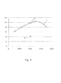
- FIG. 3 shows in a schematic embodiment, a characteristic diagram of an internal combustion engine in which once again is shown schematically how the relative engine power results.
- the engine power in kW is shown in the characteristic diagram on the Y axis and the engine speed in rpm on the X axis.
- a desired engine power is requested by the accelerator pedal position at an operating point which is at 4,000 rpm, then a desired operating point results, which in FIG. 3 represented by the dot.
- the maximum achievable engine power at 4,000 revolutions is limited on the preload line V and marked with the point Me.
Landscapes
- Engineering & Computer Science (AREA)
- Mechanical Engineering (AREA)
- General Engineering & Computer Science (AREA)
- Chemical & Material Sciences (AREA)
- Combustion & Propulsion (AREA)
- Supercharger (AREA)
Abstract
Description
- Die vorliegende Erfindung betrifft ein Verfahren zur Einstellung eines Ladedrucks einer Verbrennungskraftmaschine gemäß den Merkmalen im Oberbegriff von Patentanspruch 1.
- Aus dem Stand der Technik ist es bekannt, Verbrennungskraftmaschinen aufzuladen, um bei gleichbleibendem Hubraum höhere Leistungsraten oder aber bei sinkende Hubraum gleichbleibende Leistungsraten zu erzielen. Hierbei wird die angesaugte Frischluft über einen Verdichter komprimiert und anschließend dem Verbrennungsvorgang zugeführt. Als Verdichtertypen sind aus dem Stand der Technik Abgas-Turbolader, Kompressoren oder aber auch Druckwellenlader bekannt.
- Beim Einsatz eines Druckwellenladers ist es seit einiger Zeit möglich, diesen durch aktive Vorgabe von Betriebsparametern auf den jeweiligen Betriebspunkt der Verbrennungskraftmaschine anzupassen. Hierdurch erfolgt eine Optimierung und somit ein höherer Wirkungsgrad in den einzelnen Betriebspunkten und/oder ein besseres und agileres Ansprechverhalten der aufgeladenen Verbrennungskraftmaschine.
- Insgesamt lässt sich so der direkte Gaskontakt von Frischgas und Abgas im Druckwellenlader, was ein großer Nachteil sein kann, bestmöglich kompensieren und stellt den Druckwellenlader somit insbesondere in Bezug auf die aktuelle Forderung des Downsizing im Motorenbau als interessante Alternative zum Turbolader oder aber Kompressor dar. Die bisher bekannten Regelungsmodelle basieren auf statischer Veränderung einzelner Betriebsparameter, die aufgrund von Sensorik oder aber Rechentableaus bzw. hinterlegten Kennfeldern über ein Steuergerät an die Aktuatoren weitergegeben werden.
- Aus der
DE 10 2006 020 522 A1 ist ein Verfahren zum Betreiben einer Verbrennungskraftmaschine bekannt, bei dem Frischluft durch einen Druckwellenlader komprimiert wird, wobei mindestens ein Betriebsparameter des Druckwellenladers, abhängig von mindestens einer Ist-Betriebsgröße der Verbrennungskraftmaschine, gesteuert oder geregelt wird. Das dort offenbarte Verfahren bedeutet insofern eine Abkehr von den bisherigen starren und im Wesentlichen ungesteuerten bzw. ungeregelten Betriebskonzepten von Druckwellenladern. - Durch die Anpassung des jeweiligen Betriebszustandes des Druckwellenladers an den Betriebszustand der Verbrennungskraftmaschine werden Pumpverluste der Verbrennungskraftmaschine minimiert. Auch kann auf diese Weise das Ansprechverhalten des Druckwellenladers und somit der Verbrennungskraftmaschine verbessert werden und es können die Bedingungen für eine Abgasnachbehandlung optimiert werden.
- Aus der
40 34 341 A1 ist eine Druckwellenladeranordnung bekannt, wobei von einem abgaszuführenden Kanal ein Zufluss zu einer Gastasche abgezweigt ist und dieser Zufluss in Abhängigkeit des Ladedrucks über ein Gastaschenventil steuerbar ist. Das Gastaschenventil selbst wird dabei über eine Steuerleitung angesteuert. Der Gastaschenzufluss wird dabei unter Vermeidung einer Gasabblasung vom Hochdruckkanal in die Atmosphäre im Stillstand und im Notbetrieb der Verbrennungskraftmaschine durch Öffnen des Gastaschenzuflusses mittels Federmitteln realisiert. - Aus der
DE 698 23 039 T2 ist eine Druckwellenladeranordnung bekannt, bei der zur Verbesserung des Betriebsverhaltens des Druckwellenladers und der Brennkraftmaschine zueinander ein drehbares Kaltgasgehäuse angeordnet ist. Das drehbare Kaltgasgehäuse wird dabei im Betrieb des Druckwellenladers eingeregelt, um den Betrieb des Druckwellenladers über den gesamten Kennfeldbereich der Verbrennungskraftmaschine zu verbessern. - Die aus dem Stand der Technik bekannten Regelungs- und Steuerungsverfahren für Druckwellenlader benötigen jedoch den Einsatz einer Vielzahl von Sensoren und Steuergeräten, die für einen Serieneinsatz, gerade im Kleinfahrzeugsegment, uninteressant sind. Ebenfalls wird durch die vielfach verbaute Sensorik eine hohe Störanfälligkeit bedingt. Der Einsatz von redundanten Sensorsystemen würde hier zu noch höheren Herstellungs- und Wartungskosten führen.
- Aufgrund der Druckunterschiede zwischen Ansaugtrakt und Abgastrakt bildet sich ein gasdynamischer Vorgang in den Rotorzellen des Druckwellenladers selber, der eine schier unendliche Zahl von thermodynamischen Zustandsgrößen hervorbringt. Da diese oft nur durch sehr lange und sehr komplexe Zahlenwertgleichungen berechenbar sind, ist eine detaillierte Modellierung eines Druckwellenladers, die auf einem Steuergerät implementiert werden könnte, mit den heutigen CAE-Methoden nicht möglich.
- Aufgabe der vorliegenden Erfindung ist es daher, ein Verfahren zur Steuerung und Regelung eines Druckwellenladers bereitzustellen, welche das Emissionsverhalten, das Ansprechverhalten, die Dauerhaltbarkeit und den Wirkungsgrad eines Druckwellenladers für eine Verbrennungskraftmaschine optimiert und gleichzeitig einen von äußeren Einflüssen weitestgehend unabhängigen Serieneinsatz ermöglicht.
- Die zuvor genannte Aufgabe wird mit einem Verfahren mit den Merkmalen von Patentanspruch 1 gelöst.
- Vorteilhafte Weiterbildungen des erfindungsgemäßen Verfahrens sind Bestandteil der abhängigen Patentansprüche.
- Das erfindungsgemäße Verfahren zur Einstellung eines Ladedrucks einer Verbrennungskraftmaschine, wobei der Ladedruck durch einen Druckwellenlader aufgebaut wird, welcher einen Zellrotor und ein Zellrotorgehäuse aufweist und an den Druckwellenlader ein Kanal 1 zum Ansaugen von Frischluft, ein Kanal 2 zum Abführen der komprimierten Frischluft, ein Kanal 3 zum Zuführen von Abgas und ein Kanal 4 zum Abführen von Abgas angeschlossen sind und der Druckwellenlader ein Kaltgasgehäuse, an dem Kanal 1 und Kanal 2 angeschlossen sind, und ein Gastaschenventil, das im Bereich des Kanal 3 angeordnet ist, aufweist, zeichnet sich dadurch aus, dass eine Position des Stellelements in Abhängigkeit einer Differenz zwischen dem Ist-Wert und dem Soll-Wert der Gastaschenventilstellung eingestellt und/oder geregelt wird.
- Im Rahmen der Erfindung handelt es sich bei dem Stellelement um ein verdrehbares Gehäuse, ein Stellelement, einen Kantenschieber oder aber eine Steuerwalze, die über einen geometrischen Versatz von Kanal 3 und Kanal 4 zu Kanal 1 und Kanal 2 die Ein- bzw. Austrittsöffnungen variabel verändern kann. Vorzugsweise ist das Stellelement im Rahmen der Erfindung an der Kaltgasseite des Druckwellenladers angeordnet. Es kann jedoch auch an der Heißgasseite angeordnet sein.
- Im Rahmen der Erfindung ist weiterhin das Gastaschenventil, welches im Bereich von Kanal 3 angeordnet ist, ein Blowby-Ventil, welches den Gasdurchsatz in einem Kanal 3' regelt. Der Kanal 3' grenzt dabei an Kanal 3 an und führt ebenfalls direkt in die Rotorzellen des Zellrotors. Über das Gastaschenventil ist eine variable Öffnung von 0 bis 100 % des Kanals 3'möglich. Das Gastaschenventil kann im Rahmen der Erfindung dabei auch einen direkten Bypass zwischen Kanal 3 und Kanal 4 ausbilden. Ebenfalls kann über das Gastaschenventil dann die Öffnung des Bypasses von Kanal 3 zu Kanal 4 variabel geregelt werden.
- Das erfindungsgemäße Verfahren bietet daher eine Lösung zur optimalen, dynamischen Einstellung des Motorbetriebszustandes auf Basis von Energieänderungen, welche in Kanal 3 anliegen. Bei dem dynamischen Regelungsverfahren ändert sich vordergründig die Anforderung an den Ladedruck-Sollwert. Eine Regelung und Steuerung des Ladedruck-Sollwertes erfolgt über die Gastaschenventilstellung. Die Positionsänderung des Gastaschenventils erzeugt einen Energieimpuls im Kanal 3 des Druckwellenladers. Diese Energieänderung wirkt sich in den Zellen des Zellrotors aus und somit auf die zu komprimierende bzw. komprimierte Frischluft. Um hier einen Abgasdurchbruch von Kanal 3 in Kanal 2 zu verhindern, wird das Stellelement mit einem Korrekturwert in Abhängigkeit der Positionsänderung des Gastaschenventils eingestellt. Insbesondere wird hier der Relativwert der Differenz der Gastaschenventilstellung als Regelgröße ausgewertet und ein Korrekturwert als Relativwert als Steuerungssignal wiedergeben.
- Bei dynamischen Regelungsverfahren zur Positionsänderung des Stellelements ist eine weitere wichtige bevorzugte Eingangsgröße die Motordrehzahl der Verbrennungskraftmaschine. Hierzu ist zunächst eine Eingrenzung der aktuellen Position des Stellelements wichtig. Diese wird vorzugsweise im Rahmen der Erfindung durch eine Kennfeldstruktur von aktuellem Ladedruck-Istwert und der Motordrehzahl der Verbrennungskraftmaschine mit eine Maximalwert und einem Minimalwert bestimmt. Zwischen dem Maximalwert und dem Minimalwert wird aufgrund der Differenz der Gastaschenventilstellung und der Motordrehzahl der Verbrennungskraftmaschine eine optimale Position des Stellelements oder aber eine Korrekturverstellung des Stellelements ermittelt.
- Durch die Eingrenzung von Maximalwert und Minimalwert der Position des Stellelements wird ein Abgasdurchbruch oder aber eine Fehlstellung des Stellelements vermieden, was sich optimierend auf das Emissionsverhalten und das Ansprechverhalten der gesamten Verbrennungskraftmaschinenanordnung auswirkt.
- Die erfindungsgemäße dynamische Ladedruckregelung kann entweder Open-Loop oder Closed-Loop stattfinden. Insgesamt lässt sich hierdurch ein bedeutend schnelleres Regelungsverhalten und damit Ansprechverhalten bei gleichzeitig geringe Hardware- und Softwareaufwand zur Regelung und Steuerung erreichen.
- Die Relativverstellung des Gastaschenventils ist die Differenz der Verstellung über die Zeit gemessen oder die Relativverstellung zwischen Ist-Wert des Gastaschenventils und Soll-Wert, welcher aus einem Kennfeld bestimmbar ist. Die optimale Position des Gastaschenventils ist die optimale Position zum Erreichen eines höchstmöglichen Wirkungsgrades im Zusammenspiel von Verbrennungskraftmaschine und Druckwellenlader. Die Differenz bzw. die Relativverstellung des Gastaschenventils im Vergleich zu der ermittelten oder aber errechneten Optimalposition ist ein Wert, welcher zeigt, wie optimal der Druckwellenprozess arbeitet. Der Retativwert kann daher als Regelgröße für die Optimierung des Druckwellenprozesses genommen werden. Wenn eine optimale Betriebsposition erreicht ist, wird die Regelgröße zur Relativverstellung des Gastaschenventils gegen Null gehen und somit auch die Korrekturen für andere Stellelemente. Die Steuerzeiten für diesen Regelungsprozess liegen im Bereich von 5 bis 10 ms.
- Im Rahmen der Erfindung ist unter einer Relativmotorleistung folgende Definition zu verstehen. Die gewünschte Motorleistung wird durch die maximal mögliche Motorleistung geteilt und mit 100% multipliziert. Dies ergibt dann eine Relativmotorleistung, die, ausgedrückt in Prozent, von der maximal möglichen Motorleistung erfassbar ist. Vorzugsweise wird die Relativmotorleistung immer bezogen auf eine Motordrehzahl gesehen. Bezogen auf ein Kennfeld, welches Leistung über Drehzahl darstellt, ist die Relativmotorleistung immer in der Vertikalen für einen Drehzahlbereich zu sehen. Da das Regelungsverfahren dynamisch ausgeführt wird, wird zwar zunächst auf der Vertikalen ein konkreter Drehzahlwert erfasst, aufgrund der zeitlich hoch aufgelösten Regelung und Steuerung ist der Prozess dennoch als dynamisch anzusehen, da eine Drehzahlsteigerung oder aber Abnahme durch die Zeitintervalle der Regelung und Steuerung berücksichtigt werden.
- Im Rahmen der Erfindung ist es ebenfalls möglich, die Steuerung und Regelung über eine Relativlast zu erreichen. Die Relativlast ist dabei die Soll-Last, welche beispielsweise durch die Fahrpedalstellung bestimmt wird geteilt durch die maximal mögliche Last der jeweiligen Drehzahl mal 100%.
- Im Rahmen der Erfindung ist eine Verbrennungsmotor-Drehmomenten-Struktur eine Strategie, auf der eine Motormanagementsteuerung aufbaut. Die gesamte Regelung des Verbrennungsmotors wird bezogen auf das Drehmoment in Nm. In so einem Fall sind der Wunsch- bzw. Sollwert und der Istwert der Steuerung auch in wiedergegeben. Die Verbrennungsmotor-Drehmomenten-Struktur kann also in Nm arbeiten, sie kann aber auch auf der Basis einer relativen Last arbeiten. Die jeweilige Verbrennungsmotor-Drehmomenten-Struktur ist herstellerspezifisc abhängig vom Steuergerät, welches an dem Verbrennungsmotor verbaut ist.
- In einer weiteren vorteilhaften Ausführungsvariante der vorliegenden Erfindung wird die Laderdrehzahl des Zellrotors in Abhängigkeit der Gastaschenventilstellung eingestellt und/oder geregelt. Bei der Laderdrehzahl handelt es sich somit um die Drehzahl des Druckwellenladers. Vorzugsweise wird dieser über einen eigenen Motor, insbesondere Elektromotor, angetrieben, weshalb die Laderdrehzahl beliebig variabel einstellbar ist. Auch hier wird besonders bevorzugt über die Differenz der Gastaschenventilstellung, also die relative Verstellung des Gastaschenventils, die Laderdrehzahl mit einem Absolutwert und/oder relativen Korrekturwert eingestellt und/oder geregelt. Insbesondere erfolgt die Regelung der Laderdrehzahl des Zellrotors kombiniert mit der Einstellung der Position des Stellelements.
- Auch bei dem dynamischen Verfahren zur Einstellung des Ladedrucks mittels der Laderdrehzahl des Zellrotors wird die Laderdrehzahl bevorzugt eingegrenzt. Die Eingrenzung kann in Abhängigkeit des Ladedruck-Istwertes und der Motordrehzahl der Verbrennungskraftmaschine bestimmt werden. Auch hier ist ein Maximalwert und ein Minimalwert der Laderdrehzahl zur Eingrenzung optional bestimmbar.
- Besonders bevorzugt werden mit den zuvor genannten Parametern Ladedruck-Istwert und Motordrehzahl der Verbrennungskraftmaschine über eine Kennfeldstruktur die oberen und unteren Grenzwerte bestimmt sowie die Korrekturwerte dazwischen ermittelt. Der so ermittelte Wert für einen Laderdrehzahl-Sollwert wird somit als Korrekturwert an die Laderdrehzahlsteuerung abgegeben.
- Weitere Vorteile, Aspekte, Merkmale und Eigenschaften der vorliegenden Erfindung ergeben sich aus der folgenden Beschreibung. Die schematischen Figuren dienen dem einfachen Verständnis der Erfindung. Es zeigen:
- Figur 1
- eine Prinzipdarstellung des Kreislaufes von Ansaugluft über die Verbrennungskraftmaschine bis zur Abgasabführung;
- Figur 2
- ein Flussdiagramm zur dynamischen Regelung der Position des Stellelements;
- Figur 3
- ein Kennfeld.
- Die
Figur 1 zeigt einen Teilbereich einer Verbrennungskraftmaschine A in einer hier dargestellten Ausführungsversion als Ottomotor. Der Druckwellenlader B weist vier an diese angeschlossene Kanäle (1, 2, 3, 4) auf. Dieses sind der Kanal 1 (1) im Bereich der angesaugten Frischluft, der Kanal 2 (2) im Bereich der komprimierten Frischluft zur Zuführung zu einem Ladeluftkühler J und einer sich daran anschließenden Drosselklappe K nach der die komprimierte Frischluft dem Brennraum 10 zugeführt wird. Weiterhin ein Kanal 3 (3), der nach dem Auslassventil 6 und einem Katalysator vor dem Druckwellenlader B angeordnet ist, um das Abgas in den Druckwellenlader B einzuführen. Ebenfalls im Kanal 3 (3) angeordnet ist ein Gastaschenventil mit einem Gastaschenventilstellmotor F. Im Bereich des Abgasstranges S weist der Druckwellenlader B den Kanal 4 (4) zur Abführung des Abgases nach dem Kompressionsvorgang im Druckwellenlader B auf. Der Kanal 4 (4) weist ebenfalls einen Oxidationskatalysator M auf. - Dargestellt ist weiterhin eine Schnittansicht durch den Zylinder, wobei ein Einlassventil 5, ein Auslassventil 6, ein Kolben 7, eine Zündkerze 8, eine Einspritzdüse 9 und ein Brennraum 10 gezeigt ist. An die Brennkraftmaschine A ist ein Druckwellenlader B angeschlossen.
- Der Druckwellenlader B weist weiterhin eine Kaltgasgehäuseseite 11 sowie eine Heißgasgehäuseseite 12 auf. In der Kaltgasgehäusehälfte 11 ist ein Stellelement D angeordnet. Das Stellelement D wird durch einen Steuerscheibenstellmotor angesteuert. Der in dem Druckwellenlader B angeordnete Rotor C wird über einen elektrischen Rotormotor E angesteuert.
- Die angesaugte Frischluft folgt einem Weg durch den Kanal 1 (1) in die jeweils am Kanal 1(1) anliegend Rotorzelle 13 und wird im Druckwellenlader B komprimiert. Die komprimierte Luft wird dann im Auslassbereich des Kanals 2 (2) über den Kanal 2 (2) dem Einlassventil 5 zugeführt. Hierbei ist dem zwischengeschaltet noch ein Umluftventil mit dazugehörigen Stellmotor H in Kanal 2 (2) angeordnet, um den Ladeluftkühler und den Brennraum 10 durch eine Bypassleitung zu umgehen. Im Ladeluftkühler J wird die komprimierte und erhitzte Luft abgekühlt, so dass sich ihr Volumen verkleinert, was zu einem höheren Zylinderfüllungsgrad im Brennraum 10 führt.
- Es folgt der Einlasstakt, gefolgt von dem Kompressionstakt, dem Verbrennungstakt und dem Auslasstakt am Beispiel des Viertaktmotors. Im Rahmen der Erfindung ist aber auch die Verwendung für einen anders getakteten Motor vorstellbar.
- Im Auslasstakt wird das im Brennraum 10 gebildete Abgas durch den Kanal 3 (3) dem Druckwellenlader B wieder auf der Heißgasseite zugeführt. Dabei ist ein Katalysator L zwischengeschaltet, der eine erste Abgasnachbehandlung vornimmt. Im Kanal 3'(3') befindet sich das Gastaschenventil F, das angetrieben über einen Gastaschenventilstellmotor F einen vermehrten Eintritt von Restgas in die Rotorzellen 13 über die Einlassöffnung des Kanals 3' (3') ermöglicht und/oder Abgas vorbei am Rotor führt direkt in Kanal 4 (4). Im Rahmen der Erfindung ist es auch möglich das Abgas direkt über das Gastaschenventil von Kanal 3' (3') in Kanal 4 (4) zu leiten.
- Die Druckwelle komprimiert die durch den Kanal 1 angesaugte Frischluft und sorgt dafür, dass die komprimierte Frischluft in den Kanal 2 (2) strömt und wird anschließend durch die Auslassöffnung der Rotorzellen am Kanal 4 (4) in den Abgasstrang überführt. Das Abgas durchströmt dann gegebenenfalls weitere Abgasnachbehandlungskomponenten, beispielsweise in Form eines Oxidationskatalysators M.
- Weiterhin sind in der
Figur 1 Messpunkte angegeben, die mögliche Abgriffe von benötigten Betriebsgrößen darstellen. Position 1 zeigt einen Abgriff von Messdaten im Ansaugbereich der Frischluft. Pos. 2 US zeigt einen Abgriff von Messgrößen im Bereich der verdichteten Frischluft vor dem Ladeluftkühler J. Pos. 2 DS zeigt einen Abgriff nach der Drosselklappe K kurz vor dem Einlassventil 5 der Verbrennungskraftmaschine A. Pos. 3 US zeigt einen möglichen Abgriffspunkt im anal 3 (3). Pos. 3 DS zeigt einen Messpunkt im Kanal 3 (3) vor dem Eintritt in den Druckwellenlader B. Die Pos. 3 US und 3 DS sind jeweils so gewählt, dass sie den Gesamtstrom nach bzw. vor dem Umluftventil H bzw. Gastaschenventil F messen, um so Messdaten für eine Umluftventilstellung oder Gastaschenventilstellung zu liefern. - Pos. 4 zeigt einen möglichen Messpunkt im Abgasstrang S nach dem Druckwellenlader B. Die hier dargestellten Messpositionen haben sich im Rahmen der Erfindung als vorteilig erwiesen, können jedoch je nach Anwendungsfall um weitere Messpositionen ergänzt oder verringert werden und auch in ihrer örtlichen Position frei wählbar gesetzt werden.
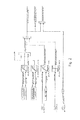
- Die nachfolgend eingefügte Tabelle beschreibt ein mögliches Regelungs- und Steuerungsflussdiagramm gemäß
Figur 2 .Parametername Beschreibung gpv_ctrl_pre_boost_atm_map Gastaschenventil pre-controll Kennfeld für optimal Atmospherical Kondition gpv_ctrl_pre_boost_cor_texh Gastaschenventil pre-controll Korrektur Kennfeld im Abhängigkeit von Abgastemperatur_vorDruckwellenlader gpv_otrl_pre_boost_corr_teng Gastaschenventil pre-controll Korrektur Kennfeld im Abhängigkeit von Motor Temperatur gpv_ctrl_pre_boost_map Gastaschenventil pre-controll Kennfeld gpv_meas Aktuelle Position des Gastaschenventil gpv_Neng Drehzahl des Verbrennungsmotors nmot_w_rpm Drehzahl von Verbrennungsmotors _prc_gpv_boost_aim Sollwert Ladedruck prc_gpv_diff_trans_corr_perc Prozessdifferenz im Gastaschenventil für Transient Verfahren prc_gpv_ol_cl_flag Flag fur Open- oder Closed-loop control Gastaschenventil prc_gpv_pre_boost_perc Prozess Sollwert Gastaschenventil vor Korrektur prc_gpv_pre_boost_corr_texh perc Prozess Gastasohenventil- Korrektur im Abhängigkeit von Abgastemperatur vor Druckwellenlader prc_gpv_pre_boost_corr_teng_perc Prozess Gastaschenventil Korrektur im Abhängigkeit von Verbrennungsmotor Temperatur prc_gpv_pre_boost_corr_perc Prozess Sollwert Gastaschenventil nach Korrektur tanvkm w Temperatur Abgas vor Druckwellenlader tmot_w Temperatur Kühlwasser Verbrennungsmotor -
Figur 3 zeigt in schematischer Ausführungsvariante ein Kennfeld einer Verbrennungskraftmaschine, in dem noch einmal schematisch dargestellt wird, wie sich die Relativmotorleistung ergibt. Zunächst ist in dem Kennfeld auf der Y-Achse die Motorleistung in kW dargestellt und auf der X-Achse die Motordrehzahl in U/min. Wird beispielsweise bei einem Betriebspunkt, welcher sich bei 4.000 U/min befindet, eine Wunschmotorleistung durch die Fahrpedalstellung angefordert, so ergibt sich ein Wunschbetriebspunkt, welcher inFigur 3 mit dem Punkt dargestellt ist. In Relation hierzu ist an der Vorlastlinie V die maximal erreichbare Motorleistung bei 4.000 Umdrehungen begrenzt und mit dem Punkt Meingezeichnet. Wird nun die gewünschte Motorleistung durch die maximal mögliche Motorleistung geteilt und mit 100 multipliziert, so ergibt sich die Relativmotorleistung in %. Als Formel ausgedrückt ergibt sich folgendes:
-
- 1 -
- Kanal 1
- 2 -
- Kanal 2
- 3 -
- Kanal 3
- 3'-
- Kanal 3'
- 4 -
- Kanal 4
- 5 -
- Einlassventil
- 6 -
- Auslassventil
- 7 -
- Kolben
- 8 -
- Zündkerze
- 9 -
- Einspritzdüse
- 10 -
- Brennraum
- 11 -
- Kaltgasgehäuseseite
- 12 -
- Heißgasgehäuseseite
- 13 -
- Rotorzelle
- 14 -
- Auswerte-/Rechenmodul
- A -
- Verbrennungskraftmaschine
- B -
- Druckwellenlader
- C -
- Rotor
- D -
- Stellelement
- E -
- Rotormotor
- F -
- Gastaschenventil + Motor
- G -
- Steuerscheibenmotor
- H -
- luftventil + Motor
- I -
- Luftfilter
- J -
- Ladeluftkühler
- K -
- Drosselklappe
- L -
- Katalysator
- M -
- -Oxidationskatalysator
- MML -
- Maximalmotorleistung
- N -
- Fahrpedal
- S -
- Abgasstrang
- V -
- Volllastlinie
- WML -
- Wunschmotorleistung
Claims (9)
- Verfahren zur Einstellung eines Ladedruckes einer Verbrennungskraftmaschine (A), wobei der Ladedruck durch einen Druckwellenlader (B) aufgebaut wird, welcher einen Zellrotor (C) und ein Zellrotorgehäuse aufweist und an den Druckwellenlader (B) ein Kanal 1 (1) zum Ansaugen von Frischluft, ein Kanal 2 (2) zum Abführen der komprimierten Frischluft, ein Kanal 3 (3) zum Zuführen von Abgas und ein Kanal 4 (4) zum Abführen von Abgas angeschlossen sind und der Druckwellenlader (B) ein Kaltgasgehäuse, an dem Kanal 1 (1) und Kanal 2 (2) angeschlossen sind, und ein Gastaschenventil (F), das im Bereich des Kanal 3 (3) angeordnet ist, aufweist, und im Kaltgasgehäuse ein Stellelement (D) zur Einstellung von Querschnittsflächen der Kanalöffnungen angeordnet ist, dadurch gekennzeichnet, dass eine Position des Stellelements (D) in Abhängigkeit einer Differenz zwischen dem Ist-Wert und dem Soll-Wert der Gastaschenventilstellung eingestellt und/oder geregelt wird.
- Verfahren nach Anspruch 1, dadurch gekennzeichnet, dass die Ist-Position des Stellelementes (D) eingegrenzt wird, wobei die Bestimmung der Ist-Position in Abhängigkeit des Ladedruck-Istwertes und/oder der Relativmotorleistung und/oder der Verbrennungsmotor-Drehmomenten-Struktur und/oder der Motordrehzahl der Verbrennungskraftmaschine (A) erfolgt.
- Verfahren nach Anspruch 1 oder 2, dadurch gekennzeichnet, dass zur Berechnung der Ist-Position des Stellelementes (D) eine Kennfeldstruktur in Abhängigkeit des Ladedruck-Istwertes und/oder der Retativmotor!eistung und/oder der Verbrennungsmotor-Drehmomenten-Struktur und/oder der Motordrehzahl der Verbrennungskraftmaschine (A) ausgewertet werden.
- Verfahren nach eine der Ansprüche 1 bis 3, dadurch gekennzeichnet, dass zur Regelung und/oder Steuerung der Position des Stellelementes ein Maximalwert und/oder ein Minimalwert für die Position in Abhängigkeit des Ladedruck-Istwertes und/oder der Relativmotorleistung und/oder der Verbrennungsmotor-Drehmomenten-Struktur und/oder der Motordrehzahl der Verbrennungskraftmaschine (A) ermittelt wird.
- Verfahren nach einem der Ansprüche 1 bis 4, dadurch gekennzeichnet, dass eine Laderdrehzahl des Zellrotors (C) in Abhängigkeit der Gastaschenventilstellung eingestellt und/oder geregelt wird.
- Verfahren nach Anspruch 5, dadurch gekennzeichnet, dass die Laderdrehzahl eingegrenzt wird, wobei die Bestimmung der Laderdrehzahl in Abhängigkeit des Ladedruck-Istwertes und/oder der Relativmotorleistung und/oder der Verbrennungsmotor-Drehmomenten-Struktur und/oder der Motordrehzahl der Verbrennungskraftmaschine (A) erfolgt.
- Verfahren nach Anspruch 5 oder 6, dadurch gekennzeichnet, dass zur Berechnung der Laderdrehzahl eine Kennfeldstruktur in Abhängigkeit des Ladedruck-Istwertes und/oder der Relativmotorleistung und/oder der Verbrennungsmotor-Drehmomenten-Struktur und/oder der Motordrehzahl der Verbrennungskraftmaschine (A) ausgewertet werden.
- Verfahren nach eine der Ansprüche 5 bis 7, dadurch gekennzeichnet, dass zur Regelung und/oder Steuerung der Laderdrehzahl ein Maximalwert und/oder ein Minimalwert für die Position in Abhängigkeit des Ladedruck-Istwertes und/oder der Relativmotorleistung und/oder der Verbrennungsmotor-Drehmomenten-Struktur und/oder der Motordrehzahl der Verbrennungskraftmaschine (A) ermittelt wird.
- Verfahren nach einem der Ansprüche 5 bis 8, dadurch gekennzeichnet, dass die Position des Stellelementes (D) und/oder die Laderdrehzahl in Abhängigkeit der Motordrehzahl der Verbrennungskraftmaschine (A) geregelt und/oder gesteuert werden.
Applications Claiming Priority (1)
| Application Number | Priority Date | Filing Date | Title |
|---|---|---|---|
| DE201110051559 DE102011051559B3 (de) | 2011-07-05 | 2011-07-05 | Verfahren zur Einstellung eines Ladedrucks einer Verbrennungskraftmaschine |
Publications (3)
| Publication Number | Publication Date |
|---|---|
| EP2543843A2 true EP2543843A2 (de) | 2013-01-09 |
| EP2543843A3 EP2543843A3 (de) | 2014-04-16 |
| EP2543843B1 EP2543843B1 (de) | 2014-10-22 |
Family
ID=46177234
Family Applications (1)
| Application Number | Title | Priority Date | Filing Date |
|---|---|---|---|
| EP20120166761 Not-in-force EP2543843B1 (de) | 2011-07-05 | 2012-05-04 | Verfahren zur Einstellung eines Ladedrucks einer Verbrennungskraftmaschine |
Country Status (3)
| Country | Link |
|---|---|
| EP (1) | EP2543843B1 (de) |
| JP (1) | JP2013015136A (de) |
| DE (1) | DE102011051559B3 (de) |
Citations (3)
| Publication number | Priority date | Publication date | Assignee | Title |
|---|---|---|---|---|
| DE4034341A1 (de) | 1989-11-16 | 1991-05-23 | Comprex Ag Baden | Verfahren und einrichtung zum betreiben einer gasdynamischen druckwellenmaschine |
| DE69823039T2 (de) | 1997-08-29 | 2004-11-25 | Swissauto Engineering S.A. | Gasdynamische druckwellenmaschine |
| DE102006020522A1 (de) | 2006-05-03 | 2007-11-08 | Robert Bosch Gmbh | Verfahren zum Betreiben einer Brennkraftmaschine |
Family Cites Families (4)
| Publication number | Priority date | Publication date | Assignee | Title |
|---|---|---|---|---|
| CH666521A5 (de) * | 1985-04-30 | 1988-07-29 | Bbc Brown Boveri & Cie | Druckwellenlader fuer einen verbrennungsmotor mit einer einrichtung zur steuerung des hochdruckabgasstromes. |
| US5724949A (en) * | 1996-11-06 | 1998-03-10 | Caterpillar Inc. | Hydraulic drive for a pressure wave supercharger utilized with an internal combustion engine |
| EP0899435B1 (de) * | 1997-08-29 | 2003-11-19 | Swissauto Engineering S.A. | Gasdynamische Druckwellenmaschine |
| JP5273255B2 (ja) * | 2009-10-30 | 2013-08-28 | トヨタ自動車株式会社 | 内燃機関の過給システム |
-
2011
- 2011-07-05 DE DE201110051559 patent/DE102011051559B3/de not_active Expired - Fee Related
-
2012
- 2012-05-04 EP EP20120166761 patent/EP2543843B1/de not_active Not-in-force
- 2012-06-26 JP JP2012142850A patent/JP2013015136A/ja active Pending
Patent Citations (3)
| Publication number | Priority date | Publication date | Assignee | Title |
|---|---|---|---|---|
| DE4034341A1 (de) | 1989-11-16 | 1991-05-23 | Comprex Ag Baden | Verfahren und einrichtung zum betreiben einer gasdynamischen druckwellenmaschine |
| DE69823039T2 (de) | 1997-08-29 | 2004-11-25 | Swissauto Engineering S.A. | Gasdynamische druckwellenmaschine |
| DE102006020522A1 (de) | 2006-05-03 | 2007-11-08 | Robert Bosch Gmbh | Verfahren zum Betreiben einer Brennkraftmaschine |
Also Published As
| Publication number | Publication date |
|---|---|
| DE102011051559B3 (de) | 2012-08-16 |
| EP2543843A3 (de) | 2014-04-16 |
| JP2013015136A (ja) | 2013-01-24 |
| EP2543843B1 (de) | 2014-10-22 |
Similar Documents
| Publication | Publication Date | Title |
|---|---|---|
| DE102012223772B4 (de) | Steuervorrichtung für Verbrennungskraftmaschine und Verfahren zum Steuern einer Verbrennungskraftmaschine | |
| DE102010048967B4 (de) | Turboladersteuerungssysteme für ein verbessertes Übergangsverhalten | |
| DE60114987T2 (de) | Regelung eines abgasturboladers mit variabler turbinengeometrie durch messung des abgasdrucks | |
| DE102017217796B4 (de) | Steuereinrichtung und Steuerverfahren für einen Auflader-ausgestatteten Verbrennungsmotor | |
| EP3034843B1 (de) | Verfahren zum steuern einer motorbremsvorrichtung sowie motorbremsvorrichtung | |
| DE102015201061B4 (de) | Pumpverlustberechnungsvorrichtung für Verbrennungsmotor | |
| AT515499B1 (de) | Verfahren zum Betreiben einer Brennkraftmaschine | |
| DE102019209028A1 (de) | Steuervorrichtung für Verbrennungsmotor | |
| DE112009000075T5 (de) | Lufteinlasssystem mit Rückführkreis | |
| DE3032218A1 (de) | Kolbenbrennkraftmaschine mit einem abgasturbolader | |
| DE102018110949A1 (de) | Steuerungsvorrichtung für einen Verbrennungsmotor mit einem Turbolader | |
| DE102010043897B4 (de) | Verfahren und Vorrichtung zum Betreiben eines Verbrennungsmotors | |
| DE102006042872B4 (de) | Verfahren zur Bestimmung des Abgasgegendrucks stromaufwärts einer Turbine eines Abgasturboladers | |
| WO2004099585A1 (de) | Verfahren zur drehzahlüberwachung eines bi-turboladers | |
| DE102017120838A1 (de) | Automatisches kalibrierungssystem und verfahren für einen dualkraftstoff-verbrennungsmotor | |
| EP2923073B1 (de) | Verfahren zum betrieb einer fremdgezündeten brennkraftmaschine mit einem abgasturbolader | |
| DE102011079726A1 (de) | Verfahren und System zur Steuerung eines Motors | |
| DE102009010633A1 (de) | Verfahren und System zur Verringerung des spezifischen Kraftstoffverbrauchs eines Motors bei instationären Betriebsbedingungen | |
| EP1788220B1 (de) | Verfahren zur Steuerung eines Turboladers mit turbinenseitiger Ladedruck-Regelung und einem Umluftventil | |
| EP2562381A1 (de) | Verfahren zur Einstellung eines Ladedruckes in einer Brennkraftmachine mit einem Druckwellenlader | |
| DE102004003607B4 (de) | Verfahren und Vorrichtung zur Steuerung eines elektrisch angetriebenen Verdichters einer Verbrennungskraftmaschine | |
| EP2543843B1 (de) | Verfahren zur Einstellung eines Ladedrucks einer Verbrennungskraftmaschine | |
| DE102007000324B4 (de) | Steuersystem für eine Brennkraftmaschine mit einem Aufladegerät | |
| DE102011081949A1 (de) | Verfahren und Vorrichtung zur Durchführung einer Regelung, insbesondere zum Einsatz in einem Kraftfahrzeug | |
| DE102011052749B4 (de) | Differenzdruckmessung an einem Druckwellenlader |
Legal Events
| Date | Code | Title | Description |
|---|---|---|---|
| PUAI | Public reference made under article 153(3) epc to a published international application that has entered the european phase |
Free format text: ORIGINAL CODE: 0009012 |
|
| AK | Designated contracting states |
Kind code of ref document: A2 Designated state(s): AL AT BE BG CH CY CZ DE DK EE ES FI FR GB GR HR HU IE IS IT LI LT LU LV MC MK MT NL NO PL PT RO RS SE SI SK SM TR |
|
| AX | Request for extension of the european patent |
Extension state: BA ME |
|
| PUAL | Search report despatched |
Free format text: ORIGINAL CODE: 0009013 |
|
| AK | Designated contracting states |
Kind code of ref document: A3 Designated state(s): AL AT BE BG CH CY CZ DE DK EE ES FI FR GB GR HR HU IE IS IT LI LT LU LV MC MK MT NL NO PL PT RO RS SE SI SK SM TR |
|
| AX | Request for extension of the european patent |
Extension state: BA ME |
|
| RIC1 | Information provided on ipc code assigned before grant |
Ipc: F04F 13/00 20090101ALN20140310BHEP Ipc: F02B 33/42 20060101AFI20140310BHEP |
|
| 17P | Request for examination filed |
Effective date: 20140423 |
|
| GRAP | Despatch of communication of intention to grant a patent |
Free format text: ORIGINAL CODE: EPIDOSNIGR1 |
|
| RIC1 | Information provided on ipc code assigned before grant |
Ipc: F02B 33/42 20060101AFI20140715BHEP Ipc: F04F 13/00 20090101ALN20140715BHEP |
|
| INTG | Intention to grant announced |
Effective date: 20140812 |
|
| GRAS | Grant fee paid |
Free format text: ORIGINAL CODE: EPIDOSNIGR3 |
|
| GRAA | (expected) grant |
Free format text: ORIGINAL CODE: 0009210 |
|
| AK | Designated contracting states |
Kind code of ref document: B1 Designated state(s): AL AT BE BG CH CY CZ DE DK EE ES FI FR GB GR HR HU IE IS IT LI LT LU LV MC MK MT NL NO PL PT RO RS SE SI SK SM TR |
|
| RAP1 | Party data changed (applicant data changed or rights of an application transferred) |
Owner name: BENTELER AUTOMOBILTECHNIK GMBH |
|
| REG | Reference to a national code |
Ref country code: GB Ref legal event code: FG4D Free format text: NOT ENGLISH |
|
| REG | Reference to a national code |
Ref country code: CH Ref legal event code: EP |
|
| REG | Reference to a national code |
Ref country code: AT Ref legal event code: REF Ref document number: 692778 Country of ref document: AT Kind code of ref document: T Effective date: 20141115 |
|
| REG | Reference to a national code |
Ref country code: IE Ref legal event code: FG4D Free format text: LANGUAGE OF EP DOCUMENT: GERMAN |
|
| REG | Reference to a national code |
Ref country code: DE Ref legal event code: R096 Ref document number: 502012001464 Country of ref document: DE Effective date: 20141204 |
|
| REG | Reference to a national code |
Ref country code: NL Ref legal event code: VDEP Effective date: 20141022 |
|
| REG | Reference to a national code |
Ref country code: LT Ref legal event code: MG4D |
|
| PG25 | Lapsed in a contracting state [announced via postgrant information from national office to epo] |
Ref country code: ES Free format text: LAPSE BECAUSE OF FAILURE TO SUBMIT A TRANSLATION OF THE DESCRIPTION OR TO PAY THE FEE WITHIN THE PRESCRIBED TIME-LIMIT Effective date: 20141022 Ref country code: NO Free format text: LAPSE BECAUSE OF FAILURE TO SUBMIT A TRANSLATION OF THE DESCRIPTION OR TO PAY THE FEE WITHIN THE PRESCRIBED TIME-LIMIT Effective date: 20150122 Ref country code: IS Free format text: LAPSE BECAUSE OF FAILURE TO SUBMIT A TRANSLATION OF THE DESCRIPTION OR TO PAY THE FEE WITHIN THE PRESCRIBED TIME-LIMIT Effective date: 20150222 Ref country code: PT Free format text: LAPSE BECAUSE OF FAILURE TO SUBMIT A TRANSLATION OF THE DESCRIPTION OR TO PAY THE FEE WITHIN THE PRESCRIBED TIME-LIMIT Effective date: 20150223 Ref country code: LT Free format text: LAPSE BECAUSE OF FAILURE TO SUBMIT A TRANSLATION OF THE DESCRIPTION OR TO PAY THE FEE WITHIN THE PRESCRIBED TIME-LIMIT Effective date: 20141022 Ref country code: NL Free format text: LAPSE BECAUSE OF FAILURE TO SUBMIT A TRANSLATION OF THE DESCRIPTION OR TO PAY THE FEE WITHIN THE PRESCRIBED TIME-LIMIT Effective date: 20141022 Ref country code: FI Free format text: LAPSE BECAUSE OF FAILURE TO SUBMIT A TRANSLATION OF THE DESCRIPTION OR TO PAY THE FEE WITHIN THE PRESCRIBED TIME-LIMIT Effective date: 20141022 |
|
| PG25 | Lapsed in a contracting state [announced via postgrant information from national office to epo] |
Ref country code: CY Free format text: LAPSE BECAUSE OF FAILURE TO SUBMIT A TRANSLATION OF THE DESCRIPTION OR TO PAY THE FEE WITHIN THE PRESCRIBED TIME-LIMIT Effective date: 20141022 Ref country code: RS Free format text: LAPSE BECAUSE OF FAILURE TO SUBMIT A TRANSLATION OF THE DESCRIPTION OR TO PAY THE FEE WITHIN THE PRESCRIBED TIME-LIMIT Effective date: 20141022 Ref country code: GR Free format text: LAPSE BECAUSE OF FAILURE TO SUBMIT A TRANSLATION OF THE DESCRIPTION OR TO PAY THE FEE WITHIN THE PRESCRIBED TIME-LIMIT Effective date: 20150123 Ref country code: LV Free format text: LAPSE BECAUSE OF FAILURE TO SUBMIT A TRANSLATION OF THE DESCRIPTION OR TO PAY THE FEE WITHIN THE PRESCRIBED TIME-LIMIT Effective date: 20141022 Ref country code: PL Free format text: LAPSE BECAUSE OF FAILURE TO SUBMIT A TRANSLATION OF THE DESCRIPTION OR TO PAY THE FEE WITHIN THE PRESCRIBED TIME-LIMIT Effective date: 20141022 Ref country code: SE Free format text: LAPSE BECAUSE OF FAILURE TO SUBMIT A TRANSLATION OF THE DESCRIPTION OR TO PAY THE FEE WITHIN THE PRESCRIBED TIME-LIMIT Effective date: 20141022 Ref country code: HR Free format text: LAPSE BECAUSE OF FAILURE TO SUBMIT A TRANSLATION OF THE DESCRIPTION OR TO PAY THE FEE WITHIN THE PRESCRIBED TIME-LIMIT Effective date: 20141022 |
|
| REG | Reference to a national code |
Ref country code: DE Ref legal event code: R097 Ref document number: 502012001464 Country of ref document: DE |
|
| PG25 | Lapsed in a contracting state [announced via postgrant information from national office to epo] |
Ref country code: EE Free format text: LAPSE BECAUSE OF FAILURE TO SUBMIT A TRANSLATION OF THE DESCRIPTION OR TO PAY THE FEE WITHIN THE PRESCRIBED TIME-LIMIT Effective date: 20141022 Ref country code: DK Free format text: LAPSE BECAUSE OF FAILURE TO SUBMIT A TRANSLATION OF THE DESCRIPTION OR TO PAY THE FEE WITHIN THE PRESCRIBED TIME-LIMIT Effective date: 20141022 Ref country code: CZ Free format text: LAPSE BECAUSE OF FAILURE TO SUBMIT A TRANSLATION OF THE DESCRIPTION OR TO PAY THE FEE WITHIN THE PRESCRIBED TIME-LIMIT Effective date: 20141022 Ref country code: SK Free format text: LAPSE BECAUSE OF FAILURE TO SUBMIT A TRANSLATION OF THE DESCRIPTION OR TO PAY THE FEE WITHIN THE PRESCRIBED TIME-LIMIT Effective date: 20141022 Ref country code: RO Free format text: LAPSE BECAUSE OF FAILURE TO SUBMIT A TRANSLATION OF THE DESCRIPTION OR TO PAY THE FEE WITHIN THE PRESCRIBED TIME-LIMIT Effective date: 20141022 |
|
| PLBE | No opposition filed within time limit |
Free format text: ORIGINAL CODE: 0009261 |
|
| STAA | Information on the status of an ep patent application or granted ep patent |
Free format text: STATUS: NO OPPOSITION FILED WITHIN TIME LIMIT |
|
| PG25 | Lapsed in a contracting state [announced via postgrant information from national office to epo] |
Ref country code: IT Free format text: LAPSE BECAUSE OF FAILURE TO SUBMIT A TRANSLATION OF THE DESCRIPTION OR TO PAY THE FEE WITHIN THE PRESCRIBED TIME-LIMIT Effective date: 20141022 |
|
| 26N | No opposition filed |
Effective date: 20150723 |
|
| REG | Reference to a national code |
Ref country code: CH Ref legal event code: PL |
|
| PG25 | Lapsed in a contracting state [announced via postgrant information from national office to epo] |
Ref country code: MC Free format text: LAPSE BECAUSE OF FAILURE TO SUBMIT A TRANSLATION OF THE DESCRIPTION OR TO PAY THE FEE WITHIN THE PRESCRIBED TIME-LIMIT Effective date: 20141022 Ref country code: CH Free format text: LAPSE BECAUSE OF NON-PAYMENT OF DUE FEES Effective date: 20150531 Ref country code: LU Free format text: LAPSE BECAUSE OF FAILURE TO SUBMIT A TRANSLATION OF THE DESCRIPTION OR TO PAY THE FEE WITHIN THE PRESCRIBED TIME-LIMIT Effective date: 20150504 Ref country code: LI Free format text: LAPSE BECAUSE OF NON-PAYMENT OF DUE FEES Effective date: 20150531 |
|
| REG | Reference to a national code |
Ref country code: IE Ref legal event code: MM4A |
|
| PG25 | Lapsed in a contracting state [announced via postgrant information from national office to epo] |
Ref country code: SI Free format text: LAPSE BECAUSE OF FAILURE TO SUBMIT A TRANSLATION OF THE DESCRIPTION OR TO PAY THE FEE WITHIN THE PRESCRIBED TIME-LIMIT Effective date: 20141022 |
|
| PG25 | Lapsed in a contracting state [announced via postgrant information from national office to epo] |
Ref country code: IE Free format text: LAPSE BECAUSE OF NON-PAYMENT OF DUE FEES Effective date: 20150504 |
|
| REG | Reference to a national code |
Ref country code: FR Ref legal event code: PLFP Year of fee payment: 5 |
|
| PGFP | Annual fee paid to national office [announced via postgrant information from national office to epo] |
Ref country code: GB Payment date: 20160520 Year of fee payment: 5 Ref country code: DE Payment date: 20160519 Year of fee payment: 5 |
|
| PGFP | Annual fee paid to national office [announced via postgrant information from national office to epo] |
Ref country code: FR Payment date: 20160520 Year of fee payment: 5 |
|
| PG25 | Lapsed in a contracting state [announced via postgrant information from national office to epo] |
Ref country code: MT Free format text: LAPSE BECAUSE OF FAILURE TO SUBMIT A TRANSLATION OF THE DESCRIPTION OR TO PAY THE FEE WITHIN THE PRESCRIBED TIME-LIMIT Effective date: 20141022 |
|
| PG25 | Lapsed in a contracting state [announced via postgrant information from national office to epo] |
Ref country code: SM Free format text: LAPSE BECAUSE OF FAILURE TO SUBMIT A TRANSLATION OF THE DESCRIPTION OR TO PAY THE FEE WITHIN THE PRESCRIBED TIME-LIMIT Effective date: 20141022 Ref country code: BG Free format text: LAPSE BECAUSE OF FAILURE TO SUBMIT A TRANSLATION OF THE DESCRIPTION OR TO PAY THE FEE WITHIN THE PRESCRIBED TIME-LIMIT Effective date: 20141022 Ref country code: HU Free format text: LAPSE BECAUSE OF FAILURE TO SUBMIT A TRANSLATION OF THE DESCRIPTION OR TO PAY THE FEE WITHIN THE PRESCRIBED TIME-LIMIT; INVALID AB INITIO Effective date: 20120504 |
|
| PG25 | Lapsed in a contracting state [announced via postgrant information from national office to epo] |
Ref country code: BE Free format text: LAPSE BECAUSE OF NON-PAYMENT OF DUE FEES Effective date: 20150531 |
|
| PG25 | Lapsed in a contracting state [announced via postgrant information from national office to epo] |
Ref country code: TR Free format text: LAPSE BECAUSE OF FAILURE TO SUBMIT A TRANSLATION OF THE DESCRIPTION OR TO PAY THE FEE WITHIN THE PRESCRIBED TIME-LIMIT Effective date: 20141022 |
|
| REG | Reference to a national code |
Ref country code: DE Ref legal event code: R119 Ref document number: 502012001464 Country of ref document: DE |
|
| GBPC | Gb: european patent ceased through non-payment of renewal fee |
Effective date: 20170504 |
|
| REG | Reference to a national code |
Ref country code: FR Ref legal event code: ST Effective date: 20180131 |
|
| PG25 | Lapsed in a contracting state [announced via postgrant information from national office to epo] |
Ref country code: DE Free format text: LAPSE BECAUSE OF NON-PAYMENT OF DUE FEES Effective date: 20171201 Ref country code: GB Free format text: LAPSE BECAUSE OF NON-PAYMENT OF DUE FEES Effective date: 20170504 |
|
| PG25 | Lapsed in a contracting state [announced via postgrant information from national office to epo] |
Ref country code: FR Free format text: LAPSE BECAUSE OF NON-PAYMENT OF DUE FEES Effective date: 20170531 |
|
| PG25 | Lapsed in a contracting state [announced via postgrant information from national office to epo] |
Ref country code: MK Free format text: LAPSE BECAUSE OF FAILURE TO SUBMIT A TRANSLATION OF THE DESCRIPTION OR TO PAY THE FEE WITHIN THE PRESCRIBED TIME-LIMIT Effective date: 20141022 |
|
| REG | Reference to a national code |
Ref country code: AT Ref legal event code: MM01 Ref document number: 692778 Country of ref document: AT Kind code of ref document: T Effective date: 20170504 |
|
| PG25 | Lapsed in a contracting state [announced via postgrant information from national office to epo] |
Ref country code: AT Free format text: LAPSE BECAUSE OF NON-PAYMENT OF DUE FEES Effective date: 20170504 |
|
| PG25 | Lapsed in a contracting state [announced via postgrant information from national office to epo] |
Ref country code: AL Free format text: LAPSE BECAUSE OF FAILURE TO SUBMIT A TRANSLATION OF THE DESCRIPTION OR TO PAY THE FEE WITHIN THE PRESCRIBED TIME-LIMIT Effective date: 20141022 |