EP2543830A2 - Method of operation of an absorption power cycle for a binary mixture of ammonia and water - Google Patents
Method of operation of an absorption power cycle for a binary mixture of ammonia and water Download PDFInfo
- Publication number
- EP2543830A2 EP2543830A2 EP12004898A EP12004898A EP2543830A2 EP 2543830 A2 EP2543830 A2 EP 2543830A2 EP 12004898 A EP12004898 A EP 12004898A EP 12004898 A EP12004898 A EP 12004898A EP 2543830 A2 EP2543830 A2 EP 2543830A2
- Authority
- EP
- European Patent Office
- Prior art keywords
- solution
- pressure
- steam
- low
- heat
- Prior art date
- Legal status (The legal status is an assumption and is not a legal conclusion. Google has not performed a legal analysis and makes no representation as to the accuracy of the status listed.)
- Granted
Links
- XLYOFNOQVPJJNP-UHFFFAOYSA-N water Substances O XLYOFNOQVPJJNP-UHFFFAOYSA-N 0.000 title claims abstract description 100
- 238000000034 method Methods 0.000 title claims abstract description 71
- 238000010521 absorption reaction Methods 0.000 title claims description 137
- QGZKDVFQNNGYKY-UHFFFAOYSA-N Ammonia Chemical compound N QGZKDVFQNNGYKY-UHFFFAOYSA-N 0.000 title claims description 100
- 239000000203 mixture Substances 0.000 title claims description 56
- 229910021529 ammonia Inorganic materials 0.000 title claims description 51
- 238000004821 distillation Methods 0.000 claims abstract description 20
- 239000006096 absorbing agent Substances 0.000 claims description 126
- 238000012546 transfer Methods 0.000 claims description 48
- 238000001704 evaporation Methods 0.000 claims description 21
- 238000001179 sorption measurement Methods 0.000 claims description 21
- 238000000605 extraction Methods 0.000 claims description 17
- 239000007788 liquid Substances 0.000 claims description 16
- 238000001816 cooling Methods 0.000 claims description 11
- 230000001965 increasing effect Effects 0.000 claims description 11
- 239000000126 substance Substances 0.000 claims description 11
- 238000009833 condensation Methods 0.000 claims description 9
- 230000005494 condensation Effects 0.000 claims description 9
- 239000012530 fluid Substances 0.000 claims description 7
- 239000002826 coolant Substances 0.000 claims description 4
- 230000008020 evaporation Effects 0.000 claims description 4
- 230000017525 heat dissipation Effects 0.000 claims description 4
- 238000000926 separation method Methods 0.000 claims description 4
- 239000000654 additive Substances 0.000 claims description 3
- 230000000996 additive effect Effects 0.000 claims description 3
- 238000010992 reflux Methods 0.000 claims description 3
- 239000002904 solvent Substances 0.000 claims description 3
- 239000003990 capacitor Substances 0.000 claims description 2
- 238000003303 reheating Methods 0.000 claims description 2
- 238000007599 discharging Methods 0.000 claims 3
- 239000003795 chemical substances by application Substances 0.000 claims 1
- 230000002040 relaxant effect Effects 0.000 abstract description 2
- 239000000243 solution Substances 0.000 description 393
- 230000008569 process Effects 0.000 description 32
- 238000010438 heat treatment Methods 0.000 description 15
- 208000002352 blister Diseases 0.000 description 8
- 238000013461 design Methods 0.000 description 7
- 241000196324 Embryophyta Species 0.000 description 6
- 230000002708 enhancing effect Effects 0.000 description 6
- 230000008901 benefit Effects 0.000 description 5
- 238000009835 boiling Methods 0.000 description 5
- 238000010276 construction Methods 0.000 description 5
- 238000013021 overheating Methods 0.000 description 5
- 230000009467 reduction Effects 0.000 description 5
- 238000005057 refrigeration Methods 0.000 description 5
- 229920006395 saturated elastomer Polymers 0.000 description 5
- 238000010792 warming Methods 0.000 description 5
- 230000007423 decrease Effects 0.000 description 4
- 238000007872 degassing Methods 0.000 description 4
- 230000002349 favourable effect Effects 0.000 description 4
- 238000010586 diagram Methods 0.000 description 3
- 230000000694 effects Effects 0.000 description 3
- 238000010079 rubber tapping Methods 0.000 description 3
- 206010016352 Feeling of relaxation Diseases 0.000 description 2
- 238000013459 approach Methods 0.000 description 2
- 238000004364 calculation method Methods 0.000 description 2
- 230000000052 comparative effect Effects 0.000 description 2
- 239000000498 cooling water Substances 0.000 description 2
- 238000003795 desorption Methods 0.000 description 2
- 230000005611 electricity Effects 0.000 description 2
- 230000000977 initiatory effect Effects 0.000 description 2
- 238000009434 installation Methods 0.000 description 2
- 238000004519 manufacturing process Methods 0.000 description 2
- 239000000463 material Substances 0.000 description 2
- 238000010248 power generation Methods 0.000 description 2
- 238000011084 recovery Methods 0.000 description 2
- 238000004064 recycling Methods 0.000 description 2
- 239000002594 sorbent Substances 0.000 description 2
- 238000011144 upstream manufacturing Methods 0.000 description 2
- NLXLAEXVIDQMFP-UHFFFAOYSA-N Ammonium chloride Substances [NH4+].[Cl-] NLXLAEXVIDQMFP-UHFFFAOYSA-N 0.000 description 1
- VHUUQVKOLVNVRT-UHFFFAOYSA-N Ammonium hydroxide Chemical compound [NH4+].[OH-] VHUUQVKOLVNVRT-UHFFFAOYSA-N 0.000 description 1
- 235000011114 ammonium hydroxide Nutrition 0.000 description 1
- 230000033228 biological regulation Effects 0.000 description 1
- 230000005540 biological transmission Effects 0.000 description 1
- 230000008859 change Effects 0.000 description 1
- 239000012141 concentrate Substances 0.000 description 1
- 230000006837 decompression Effects 0.000 description 1
- 230000003247 decreasing effect Effects 0.000 description 1
- 230000008030 elimination Effects 0.000 description 1
- 238000003379 elimination reaction Methods 0.000 description 1
- 238000005516 engineering process Methods 0.000 description 1
- 230000002631 hypothermal effect Effects 0.000 description 1
- 238000005086 pumping Methods 0.000 description 1
- 230000000630 rising effect Effects 0.000 description 1
- 239000007921 spray Substances 0.000 description 1
- 230000000153 supplemental effect Effects 0.000 description 1
- 230000007704 transition Effects 0.000 description 1
- 238000013022 venting Methods 0.000 description 1
Images


Classifications
-
- F—MECHANICAL ENGINEERING; LIGHTING; HEATING; WEAPONS; BLASTING
- F01—MACHINES OR ENGINES IN GENERAL; ENGINE PLANTS IN GENERAL; STEAM ENGINES
- F01K—STEAM ENGINE PLANTS; STEAM ACCUMULATORS; ENGINE PLANTS NOT OTHERWISE PROVIDED FOR; ENGINES USING SPECIAL WORKING FLUIDS OR CYCLES
- F01K25/00—Plants or engines characterised by use of special working fluids, not otherwise provided for; Plants operating in closed cycles and not otherwise provided for
- F01K25/08—Plants or engines characterised by use of special working fluids, not otherwise provided for; Plants operating in closed cycles and not otherwise provided for using special vapours
-
- F—MECHANICAL ENGINEERING; LIGHTING; HEATING; WEAPONS; BLASTING
- F01—MACHINES OR ENGINES IN GENERAL; ENGINE PLANTS IN GENERAL; STEAM ENGINES
- F01K—STEAM ENGINE PLANTS; STEAM ACCUMULATORS; ENGINE PLANTS NOT OTHERWISE PROVIDED FOR; ENGINES USING SPECIAL WORKING FLUIDS OR CYCLES
- F01K23/00—Plants characterised by more than one engine delivering power external to the plant, the engines being driven by different fluids
- F01K23/02—Plants characterised by more than one engine delivering power external to the plant, the engines being driven by different fluids the engine cycles being thermally coupled
- F01K23/06—Plants characterised by more than one engine delivering power external to the plant, the engines being driven by different fluids the engine cycles being thermally coupled combustion heat from one cycle heating the fluid in another cycle
- F01K23/10—Plants characterised by more than one engine delivering power external to the plant, the engines being driven by different fluids the engine cycles being thermally coupled combustion heat from one cycle heating the fluid in another cycle with exhaust fluid of one cycle heating the fluid in another cycle
-
- F—MECHANICAL ENGINEERING; LIGHTING; HEATING; WEAPONS; BLASTING
- F01—MACHINES OR ENGINES IN GENERAL; ENGINE PLANTS IN GENERAL; STEAM ENGINES
- F01K—STEAM ENGINE PLANTS; STEAM ACCUMULATORS; ENGINE PLANTS NOT OTHERWISE PROVIDED FOR; ENGINES USING SPECIAL WORKING FLUIDS OR CYCLES
- F01K25/00—Plants or engines characterised by use of special working fluids, not otherwise provided for; Plants operating in closed cycles and not otherwise provided for
- F01K25/06—Plants or engines characterised by use of special working fluids, not otherwise provided for; Plants operating in closed cycles and not otherwise provided for using mixtures of different fluids
- F01K25/065—Plants or engines characterised by use of special working fluids, not otherwise provided for; Plants operating in closed cycles and not otherwise provided for using mixtures of different fluids with an absorption fluid remaining at least partly in the liquid state, e.g. water for ammonia
-
- F—MECHANICAL ENGINEERING; LIGHTING; HEATING; WEAPONS; BLASTING
- F01—MACHINES OR ENGINES IN GENERAL; ENGINE PLANTS IN GENERAL; STEAM ENGINES
- F01K—STEAM ENGINE PLANTS; STEAM ACCUMULATORS; ENGINE PLANTS NOT OTHERWISE PROVIDED FOR; ENGINES USING SPECIAL WORKING FLUIDS OR CYCLES
- F01K25/00—Plants or engines characterised by use of special working fluids, not otherwise provided for; Plants operating in closed cycles and not otherwise provided for
- F01K25/08—Plants or engines characterised by use of special working fluids, not otherwise provided for; Plants operating in closed cycles and not otherwise provided for using special vapours
- F01K25/10—Plants or engines characterised by use of special working fluids, not otherwise provided for; Plants operating in closed cycles and not otherwise provided for using special vapours the vapours being cold, e.g. ammonia, carbon dioxide, ether
- F01K25/106—Ammonia
-
- F—MECHANICAL ENGINEERING; LIGHTING; HEATING; WEAPONS; BLASTING
- F25—REFRIGERATION OR COOLING; COMBINED HEATING AND REFRIGERATION SYSTEMS; HEAT PUMP SYSTEMS; MANUFACTURE OR STORAGE OF ICE; LIQUEFACTION SOLIDIFICATION OF GASES
- F25B—REFRIGERATION MACHINES, PLANTS OR SYSTEMS; COMBINED HEATING AND REFRIGERATION SYSTEMS; HEAT PUMP SYSTEMS
- F25B15/00—Sorption machines, plants or systems, operating continuously, e.g. absorption type
- F25B15/02—Sorption machines, plants or systems, operating continuously, e.g. absorption type without inert gas
- F25B15/04—Sorption machines, plants or systems, operating continuously, e.g. absorption type without inert gas the refrigerant being ammonia evaporated from aqueous solution
-
- F—MECHANICAL ENGINEERING; LIGHTING; HEATING; WEAPONS; BLASTING
- F25—REFRIGERATION OR COOLING; COMBINED HEATING AND REFRIGERATION SYSTEMS; HEAT PUMP SYSTEMS; MANUFACTURE OR STORAGE OF ICE; LIQUEFACTION SOLIDIFICATION OF GASES
- F25B—REFRIGERATION MACHINES, PLANTS OR SYSTEMS; COMBINED HEATING AND REFRIGERATION SYSTEMS; HEAT PUMP SYSTEMS
- F25B2400/00—General features or devices for refrigeration machines, plants or systems, combined heating and refrigeration systems or heat-pump systems, i.e. not limited to a particular subgroup of F25B
- F25B2400/14—Power generation using energy from the expansion of the refrigerant
- F25B2400/141—Power generation using energy from the expansion of the refrigerant the extracted power is not recycled back in the refrigerant circuit
-
- Y—GENERAL TAGGING OF NEW TECHNOLOGICAL DEVELOPMENTS; GENERAL TAGGING OF CROSS-SECTIONAL TECHNOLOGIES SPANNING OVER SEVERAL SECTIONS OF THE IPC; TECHNICAL SUBJECTS COVERED BY FORMER USPC CROSS-REFERENCE ART COLLECTIONS [XRACs] AND DIGESTS
- Y02—TECHNOLOGIES OR APPLICATIONS FOR MITIGATION OR ADAPTATION AGAINST CLIMATE CHANGE
- Y02B—CLIMATE CHANGE MITIGATION TECHNOLOGIES RELATED TO BUILDINGS, e.g. HOUSING, HOUSE APPLIANCES OR RELATED END-USER APPLICATIONS
- Y02B30/00—Energy efficient heating, ventilation or air conditioning [HVAC]
- Y02B30/62—Absorption based systems
- Y02B30/625—Absorption based systems combined with heat or power generation [CHP], e.g. trigeneration
Definitions
- the invention relates to a method of operation of a sorption cycle in a sorption plant for the two-substance mixture ammonia and water for generating mechanical energy and / or cooling capacity from at least one external heat source, preferably from a low-temperature heat source.
- Kalina has developed power plant cycles in more than 20 inventions, the common feature of which is the use of ammonia and water.
- circuit KCS 34 to Mlcak Geothermal Resources Council Meeting 2002 Reno 2002 p.707-713 . It is a saturated steam process with the phase transitions occurring through desorption and absorption.
- Figure IV-22 compares the relaxation of a vapor with a water weight fraction of 5% and 15% and the same inlet temperature of 135 ° C.
- the specific enthalpy of the vapor falls with increasing ammonia content both in the live steam and in the boil off.
- the enthalpy difference in the turbine is significantly higher in the first case.
- the specific enthalpy of the vapor decreases more strongly at low pressures than at high pressures.
- DE 10 2005 005 409 A1 and DE 10 2006 005 472 A1 the medium pressure expulsion is used for a double heat supply. While in DE 10 2006 005 472 A1 the entire high-pressure steam is used with two heat supply, that is in DE 10 2005 005 409 A1 only for part of the steam.
- the technical problem to be solved is for the binary substances ammonia and Water to develop a Sorptionskraftzyklus or a combination of power cycles, which increases using a heat source of relatively low temperature, the efficiency of the system over the prior art.
- the core idea of the invention is to design a working method of a sorption plant with the binary substance pair ammonia and water so that the dew point line is exceeded at least in the second part of the expansion and the expansion steam has an energetically optimal water weight fraction.
- High performances are achieved at comparatively low expeller temperatures.
- This cycle preferably has a defined water weight fraction of 3 to 10% by weight, preferably 6%; at a final pressure of relaxation of 1.2 to 4 bar, preferably from 1.5 to 2 bar.
- the inlet pressure is at least 10 bar, preferably at least 13.5 bar.
- the vapor content is set at the decompression end above the drop impact limit. With such a circuit, a not insubstantial part of the heat externally supplied during the high-pressure expulsion is transmitted to a poor solution.
- the relaxation can be done both in one and in two successive relaxation apparatuses.
- the dew point is exceeded at the latest at a pressure of 9.5 to 15 bar, preferably 13.5 bar in the depressurization, the dew point temperature (according to the database Refprop 8.0 of the National Institute of Standards and Technology) between 94.8 ° C and 107 , 9 ° C is.
- the circulation is basically designed so that the high-pressure expulsion starts from a solution which has or would have a lower temperature at said pressure level and ends with a poor solution having a higher temperature. Building on this basis, the inlet pressure is increasingly raised above 130 ° C at maximum temperatures of the external heat source.
- the superheating temperature is also increasingly raised. This exploits that the dew point temperature of the flash steam is well below the maximum temperature of the heat source, so that the expelled steam can be overheated, possibly over several tens of Kelvin.
- the proportion of water in the steam to be relaxed is always aligned with the energy optimum and is not determined by equilibrium lines at the end or beginning of the entire high-pressure expulsion.
- the absorption takes place in up to three pressure stages. Is the external heat source additional deeper than 60 to 80 Kelvin above the ambient temperature ausnutzbar, an additional circuit is arranged. With this arrangement, by means of the principle of the two-time heat supply for a part of the high-pressure steam, the pressure ratio in the expansion is increased.
- an expansion apparatus without steam tapping or a steam expansion apparatus or two expansion apparatuses can be arranged in series.
- the process feature c) is shown in the illustrations in the Figures 3 . 4 . 6 . 8th . 9
- the process feature d) is in the representations in the Figures 9 and 10 contain.
- the first three process features are in each case for the first time in 6 different combinations of high pressure expellers and their supply of the solutions to be driven and optionally a rectifier or a distillation column FIGS. 1 . 2 . 3 . 4 . 6 and 8th shown and described in the accompanying text.
- the combinations differ in two main groups:
- the main feature of the first group is that only Hochdruckaustreiber work according to the bubble principle and after the expulsion takes place a greater reduction of the water weight fraction in a rectifier or a distillation column.
- the released heat is transferred to supplied rich or enriched solution (representations in the Figures 2 . 6 . 8th ).
- the main feature of the second group is that the highest temperature range of the external heat source is exploited by a Hochlichausustreiber which operates on the trickle principle and the next lower temperature range is exploited by one or two Hochlichaustreiber or the bubble principle work (representations in the FIGS. 1 . 3 . 4 ) or according to the trickle principle with descending guidance of the expelled steam (9).
- the poor solution in the high-temperature range is used at least predominantly for high-pressure expulsion.
- the heat transfer takes place separately from the heat transfer from the external heat source.
- the poor solution or solutions for heating the rich or, enriched solution is used.
- the heat capacity of the poor solution is no longer sufficient.
- the heat source is used for their heat release for expulsion.
- the poor solutions from both circuits are used to warm up richer or, if present, enriched solution. For this purpose, their heat capacity is sufficient except at very high maximum temperatures of the external heat source.
- the circuit has two sequential relaxation apparatuses a special advantage: As is known, the power of power plants, which are heated by a heat source low temperature, significantly influenced by the cooling temperatures. That they are coupled to the ambient temperature, is to be adopted at many potential sites. In many climates, the ambient temperature varies greatly. It is possible to concentrate these fluctuations only or largely on the medium-pressure expansion apparatus and to keep the high-pressure expansion apparatus accordingly free of these fluctuations. If the external heat source also has a largely uniform heat supply, an increase in the internal efficiency of the high-pressure relaxation apparatus according to the driving style to a best point is potentially possible.
- FIG. 11 sketched solution can be arranged at a given maximum temperature of the water vapor in principle a higher evaporation pressure and thus at least in circuits without reheating a higher efficiency for the described combination compared to a sole condensation circuit with the medium water can be achieved. In many applications may be due to a reheat be dispensed with in the water cycle.
- the combination described is energetically advantageous due to the high energy efficiency of the described ammonia-water cycle.
- the heat transfer can also be carried out at two temperature levels, by the back pressure turbine, a vapor stream is taken at a higher temperature level and fed to the sorption-force cycle.
- the Kalina process KCS 34 works with the same binary mixture of ammonia and water as the invention.
- the (high pressure) expulsion starts from a rich solution with an ammonia weight fraction of 0.83 at 85.6 ° C.
- a two-phase mixture is produced and separated in the separator according to a pressure of 37.5 bar and a temperature of 136.4 ° C, a vapor from the poor solution and fed without overheating the expansion apparatus.
- the steam is expanded at a pressure ratio of 5 from 37.5 bar to 7.5 bar and 68.7 ° C and absorbed at a minimum solution temperature of 21.8 ° C.
- the low-ammonia solution after desorption is not used for expulsion, but only solution heating of the rich solution is used. For this purpose, part of the heat of absorption is also used. Part of the heat of absorption is used to warm up the rich solution.
- a same pressure ratio as for the Kalina process KCS 34 is set. It's going to be a circuit FIG. 2 set in the bill.
- the two high-pressure ejectors work on the bubble principle. One is heated by the external heat source, one by the poor solution. The expelled steam is reduced in a rectifier to a water content of 6%. The released during the rectification heat is transferred to an introduced solution, which is driven out of this also steam. The rectified steam is overheated to 135 ° C before being allowed to relax.
- the expeller pressure is 20 bar, the absorption pressure 4 bar, the minimum solution temperature 21.8 ° C, the theoretical absorption temperature to account for the necessary solution hypothermia is 1.4 K higher.
- the high-pressure expulsion begins from a rich solution with an ammonia weight fraction of 0.5611 and 82.3 ° C. It exits the externally heated high pressure expeller as a two phase mixture at 142 ° C and from the internally heated at 137 ° C. The two-phase mixture is separated into steam and poor solution and fed to the rectifier. From this occurs, the high-pressure steam at 116.6 ° C from the high-pressure steam exits at 4 bar and 61.2 ° C from the expansion apparatus. The heat source exits the superheater at 147.9 ° C and is cooled in the high pressure exhausters to 87.3 ° C, it is cooled down to solution heating to 75 ° C further.
- the cycle of the present invention is supplied with more heat from the heat source for high pressure expulsion, in the Kalina cycle the high pressure expeller is fed a higher heated rich solution and a significantly lower amount of poor solution is discharged.
- the poor solution is used for high-pressure expulsion for the purpose of heat recovery (see lines 4 and 5 in the following table). This provides 18% of the heat for high pressure expulsion and overheating.
- the specific superheat relaxation performance in the present invention is 3.7% higher. Due to the small differences, the comparison is limited to the amount of steam produced and the expansion ratio. It is assumed that in the temperature range below the high-pressure expulsion, poor solution, heat source and (only in the Kalina cycle) heat recovery from the expanded steam provide enough heat to warm the rich solution up to the boiling point.
- the internal efficiency of the expansion apparatus is set at 85%.
- the Kalina cycle would be energetically preferable to a sorptive cycle designed with an absorber and a water weight fraction of 96% flash steam.
- the cycle of the present invention therefore includes four performance enhancing process features.
- the first performance enhancing process feature of the present invention is absorption at a second pressure stage to further relax at least a portion of the vapor ( FIG. 2 ).
- a second pressure stage to further relax at least a portion of the vapor ( FIG. 2 ).
- almost half of the steam is expanded to 2.437 bar, with the outlet temperature being 46 ° C.
- the minimum solution temperature of this added absorber is also 21.8 ° C, the theoretical is 2.4 ° C higher.
- a larger amount of steam from high pressure (4 bar) to low pressure (1.5 bar) is released in the present invention according to the described principle of the two-time heat supply by means of an additional circuit.
- the heat source is cooled from 87.3 ° C to 58.6 ° C in the additional circuit medium pressure expander, it is cooled down to 51.6 ° C for solution heating. It is expelled 5,425 kg / s medium pressure steam to 4 bar.
- the flash vapor is depressurized to 4 bar and sometimes further to 1.5 bar. There are absorption pressure stages at 4 and 1.5 bar.
- the third performance enhancing feature is a third absorption step 2.664 bar inserted.
- the extraction steam is decoupled. It is with a single heat 3.6161 kg / s of high-pressure steam to 1.5 bar and 5.804 kg / s to 3 bar, relaxed with two times 7.87 kg / s heat to 1.5 bar.
- the sum of the high-pressure steam remains unchanged at 17.281 kg / s (high-pressure expulsion after FIG. 2 , Absorption and additional circulation after FIG. 6 ).
- the heat source is cooled to 58.6 ° C in the additional medium pressure expander and further to 51.2 ° C for solution heating.
- enriched solution is passed from the absorber with the lowest pressure stage into the rectifier ( FIG. 6 ).
- the pressure of the middle absorber is 2.76 bar.
- the amount of rich solution decreases (from 40.223 kg / s to 33.298 kg / s), the amount of poor solution fed to the lowest pressure absorber (22.942 kg / s to 38.406 kg / s), with a subset before Branched off high-pressure expander and used for solution heating.
- a larger amount of steam on the other two pressure levels, a smaller amount of steam is absorbed.
- the heat source is exploited to the same temperature level as the third power increase.
- the reduction of the rich solution amount caused by the fourth performance enhancing process feature is exploited to increase the utilization of the external heat source in the high pressure compressor.
- the high-pressure expulsion starts from a rich solution with an ammonia weight fraction of 0.6 and a temperature of 76.9 ° C, with heat source and poor solution are cooled to 81.9 ° C.
- the expelled and superheated high-pressure steam increases to 18.512 kg / s.
- the pressure of the middle absorber is 3 bar.
- the supplemental medium pressure adjuster is supplied with a mixture of weakly enriched and enriched solution for expulsion. Their pressure rises to 4.635 bar.
- the heat source is cooled to 50.6 ° C in the additive pressure expander and further to 45.1 ° C for solution heating.
- Kalina cycle KCS 34 With respect to the pumping power, there is no significant difference between Kalina cycle KCS 34 and the present invention: the product of rich solution times pressure difference is approximately equal.
- Both the second and third and the fourth and fifth performance-enhancing process feature increase the heat input to the system:
- the efficiency of the latter two is about twice as high as the first two. If a heat source can only be cooled to a limited extent, the elimination of the additional cycle - ie the second and third performance-enhancing process feature - is preferable when two steam withdrawals from the flash apparatus and the medium and highest absorption pressure are made
- less heat is required for expulsion in the additional medium-pressure compressor correspondingly more heat is available for high pressure expulsion and a larger amount of flash steam is produced.
- Even greater is the relative advantage to cycles in which produces almost pure ammonia vapor Their exhaled vapors have a lower enthalpy and thus higher circulation values, equivalent to higher amounts of rich solution.
- the related performance reduction is about 4% in a cycle that basically contains the five performance-enhancing process features, but designed for the relaxation overheated almost pure ammonia vapor.
- a further reduction of about 5% is due to lower enthalpy differences in the expansion process.
- the water vapor has a temperature of 150 ° C and a pressure of 1.98 bar.
- the feed water is warmed up to 150 ° C.
- the sorption cycle can be established with a few apparatuses and the solution cycle can be carried out analogously to the known refrigeration sorption cycle.
- a superheater is arranged for the flash vapor, its inlet temperature is significantly higher than in circuits that provide overheating of an almost pure ammonia vapor and the outlet temperature can be terminated without significant thermodynamic disadvantages at a greater distance to the maximum temperature of the heat source.
- the construction costs for the superheater is correspondingly smaller.
- the lowest absorption pressure can be located above ambient, eliminating the need to remove any entrained air from the solution loop while avoiding the region of high subcooling temperatures in the absorption process.
- the construction costs can optionally be further reduced.
- the degassing width of such an inserted absorber is relatively low.
- This circuit may preferably be applied at not very high maximum temperatures of the external heat source, because then no very large Entgasungsumble the sum of all three absorbers is required.
- the efficiency-increasing effect of the steam extraction is significantly higher in the present invention than that to a stage of the feedwater heating of a steam turbine. Multiple withdrawals make little sense in the present invention.
- the steam can be heated by a second heat source and heated even higher, it is expedient to lower the final pressure parallel to the rising steam temperature again up to the maximum acceptable pressure of 1.2 bar.
- This approach is very attractive at lower maximum temperature of a first external heat source with high heat capacity and a second heat source with higher maximum temperature and low heat capacity.
- the overheating of the steam is done by the second heat source.
- the specific power per kg of steam increases considerably, and thus the system output (for example, by almost a quarter, when the steam temperature is about 30 Kelvin higher than the first heat source).
- the combination with the previously described steam extraction leads in many applications to a plant increase.
- HK absorption force cycle
- HK main circuit
- the circuit is operated with the known binary binary pair ammonia as a working fluid and water as a sorbent.
- Relaxed medium-pressure steam (32) is supplied from the high-pressure relaxation apparatus (31) to a medium-pressure absorber (14) which is under almost the same pressure.
- the pressure level is referred to here as medium pressure.
- the medium-pressure absorber (14) the medium-pressure steam (32) is absorbed with heat release from the poor solution (8) (poor in working fluid).
- the dissipated heat is transferred to a cooling medium.
- water and ammonia are usually used in the dual-substance mixture cooling water.
- the cooling circuit is not shown here and in the following figures.
- the poor solution is supplied from a first high pressure expeller (9) via a first solution heat exchanger (19a). Prior to absorption, the poor solution (8) is lowered from the high pressure level to the absorber pressure by means of the first throttle (16a).
- the absorption creates a rich solution (2).
- the rich solution (2) is brought by means of a first solution pump (10) to the pressure level of the Hochdruckustusreiber.
- the rich solution (2) is passed through the path of a first solution heat exchanger (19a) to the second and third high pressure exhausters (3, 3a).
- a first Hochdruckaustreiber (9) is arranged, which is designed according to the known Rieselustreibungsus, wherein in a known manner evaporating solution and expelled steam are conducted in countercurrent and a first part of high pressure steam (28a) of ammonia and water is generated and the supplied solution is not completely evaporated, but a poor solution (8) from the hot part of the Hoch réelleausustreibers (9) is removed.
- the first high pressure expeller (9) is fed with a main stream (4) enriched solution from a separator (6) for expulsion.
- the first Hochdruckaustreiber (9) is from a first partial flow (1a) of the external Heat source heated. This is separated from the full flow of the external heat source (1).
- both partial streams (1 a, 1 b) of the external heat source are reunited and fed to a second Hochdruckaustreiber (3).
- the amount of the first partial flow (1a) of the external heat source is so dimensioned that in the first high-pressure expeller (9) the temperature difference at the beginning and at the end of the expulsion between the first partial flow (1a) of the external heat source and the main flow (4) of enriched solution low becomes.
- a second (3) and third Hochdruckaustreiber (3a) are arranged, which are designed according to the known bubble expulsion principle, being conducted in a known manner evaporating solution and expelled steam in parallel flow and in each case a two-phase mixture (5a, 5b) of ammonia and water is generated.
- the guidance of the indirectly heat-releasing media is carried out in countercurrent to the evaporating substreams of rich solutions (2a, 2b).
- the second Hochbuchausustreiber (3) is heated by the external heat source (1), the third Hochlichausustreiber (3a) of the poor solution (8).
- the second high-pressure expeller (3) is supplied with a first partial solution of rich solution (2a)
- the third high-pressure expeller (3a) is supplied with a first partial solution of rich solution (2b) for expulsion.
- These two partial streams are generated by the division of the rich solution (2) after the first solution heat exchanger (19a) into several partial streams.
- the dimensioning of the partial flows (2 a, 2 b) takes place in accordance with the economically utilisable heat content of the heating media (heat sources) supplied to the two high-pressure expulsions (3, 3 a).
- the first partial flow of the two-phase mixture (5a) is from the second Hochlichaustreiber (3)
- the second partial flow of the two-phase mixture (5b) is passed from the third Hochlichausustreiber (3a) respectively in the separator (6) and in this in a main stream (4) enriched solution and separated into a second partial flow of high pressure steam (28b).
- the second (3) and third Hoch horraustreiber (3a) are dimensioned so large that the temperature difference between driven external heat source (1) or poor solution (8) and entering sub-streams (2a, 2b) rich solution is low.
- the amount of the rich solution (2) is so dimensioned that the high-pressure steam (28) is adjusted to an energetically favorable water weight fraction, preferably of about 6%.
- This second partial flow (28b) high-pressure steam and the separated main flow (4) enriched solution have the same equilibrium line and from him the equilibrium line of the first partial flow (28a) high-pressure steam is set so that both partial streams of high-pressure steam (28a, 28b) basically the same Water weight proportion can be adjusted.
- the two partial streams (28a, 28b) are combined as high-pressure steam (28) fed to a superheater (30).
- the high-pressure steam (28) is at least slightly overheated or overheated to such an extent that the vapor fraction at the end of the expansion remains above a drop impact limit in the expansion apparatus.
- the superheated high pressure steam (29) is fed to a Hochlichentsciencesapparat (31) and there relaxed by releasing mechanical work. This is converted by means of generator (37) into electricity.
- the Hochlichentpositionsapparat (31) is first superheated steam, then relaxed after exceeding the saturated steam point, wet steam.
- the external heat source (1) is passed to the indirect heat release by the superheater (30), then divided as described into two partial streams. After heat is released in the first high-pressure expeller (9), the reunited external heat source (1) is passed through the second high-pressure expeller (3).
- the poor solution (8) withdrawn from the first high-pressure expeller (9) is first led to release heat by the third high-pressure expeller (3a), then by the first solution heat exchanger (19a). In this, the rich solution (2) is heated in countercurrent, the temperature remains below the boiling point.
- the first high pressure exporter (9) is omitted.
- the two high-pressure ejectors (3, 3a) according to the principle of bubble expulsion are designed so that the outlet temperature of the two-phase mixtures (5a, 5b) is close to the inlet temperature of the heat-emitting media (1, 8).
- a second partial solution of rich solution (2c) is introduced into the upper cold part of the rectifier (18).
- This partial stream (2c) is separated from the rich solution (2) after the first heat exchanger (19a) and is therefore already preheated at least approximately to the boiling point.
- the rectifier (18) there is a mass and heat exchange between the introduced second partial stream of rich solution (2c) and the bottom fed high-pressure steam (27), which - as known - causes a portion of this vapor condenses.
- the condensed steam is - as known - as reflux solution from the Rectifier (18) deducted.
- the rectification heat released causes expulsion of working medium vapor from the second partial flow of rich solution (2c) and the solution of this partial flow is heated.
- the second partial stream rich solution (2c) is dimensioned to receive the Rekttechnischstage. This poor solution, together with the rectification reflux, forms the amplified return (26), which is withdrawn at the bottom of the rectifier (18) and introduced into the separator (6).
- the withdrawn from the separator (6) poor solution (8) is used for heat dissipation as in FIG. 1 first through the third high pressure expeller (3a), then through the first solution heat exchanger (19a).
- high-pressure steam (28) exits, which is adjusted to a water weight fraction which is favorable for the performance of the expansion apparatus, preferably to 6 percent, via the quantity of second solution stream (2c) supplied.
- the high-pressure steam (28) is fed from the rectifier (18) to a superheater (30).
- the external heat source (1) is passed for indirect heat release successively through the superheater (30) and the second Hochdruckaustreiber (3) and a third heat exchanger (19d), so that the rich solution is warmed up to Austreibertemperatur.
- a low pressure absorber (13) for absorption of low pressure steam (33) is inserted.
- a main stream (4) of enriched solution is removed and raised by means of the second solution pump (10a) to medium-pressure level and fed to the medium-pressure absorber (14).
- the poor solution (8) is lowered in the first throttle (16a) to low pressure and fed to the low-pressure absorber (13) for absorbing the low-pressure vapor.
- the Hochlichentdozenssapparat (31 a) with removal is designed for relaxation of a partial steam flow from the high pressure level on the medium pressure level out to low pressure level.
- Low-pressure steam (33) is supplied from the high-pressure expansion apparatus with removal (31 a) to the low-pressure absorber (13).
- Medium pressure steam (32) is taken from the Hochlichentdozenssapparat (31 a) at medium pressure level and fed to the medium-pressure absorber (14).
- a first substream of enriched solution (4a) is taken from the low pressure absorber. This is brought by means of third solution pump (10b) to high pressure level and then heated in the second solution heat exchanger (19b). The first substream (4a) of enriched solution is combined with the main stream (4) of enriched solution as a full-flow enriched solution (4d) to the first high pressure expeller (9).
- a first (8a) and a second partial flow (8b) of poor solution are taken from the first high pressure expeller (9).
- the first partial flow (8a) poor solution is the third Hochdruckausustreiber (3a) supplied as a heating medium.
- a third partial flow (8c) of poor solution is separated from the first partial flow (8a) of poor solution.
- the remaining fourth partial stream (8d) of poor solution is passed through the first heat exchanger solution heat exchanger (19a).
- the second partial stream (8b) of poor solution is combined with the third partial stream (8c) of poor solution to the fifth partial stream (8e) of poor solution.
- the warming up of the first part-stream (4a) of enriched solution to the boiling point is carried out in countercurrent to the fifth part-stream (8e) of poor solution.
- the amount of this fifth partial stream (8e) poor solution is to be dimensioned accordingly, wherein the quantitative ratio of the second partial stream (8b) and the third partial stream (8c) to each other to be determined so that the temperature of the fifth partial stream (8e) poor solution slightly above the boiling point of the first part stream (4a) enriched solution is located.
- fourth (8d) and fifth (8e) partial solutions of poor solution are reunited to the poor solution (8).
- the first partial flow of high-pressure steam (28a) is likewise introduced into the separator (6).
- the high-pressure steam (28) is supplied from the first Hochlichaustreiber (9) a superheater (30). In the superheater, the high-pressure steam (28) is considerably overheated, possibly to an economically acceptable distance from the maximum temperature of the external heat source (1).
- FIG. 4 another solution for high pressure expulsion is shown and an additional circuit ("ZK") is inserted to the operated between high pressure expulsion and absorption circuit.
- ZK additional circuit
- the additional circuit is operated between low pressure and medium pressure level.
- a ZK medium pressure expander (25) is inserted and the medium pressure absorber is increased to a HK / ZK low pressure absorber (13a).
- the rich ZK solution (20) is raised by means of ZK solution pump (17) to medium pressure level and introduced via a first ZK solution heat exchanger (19c) in the ZK medium pressure expeller (25) for expulsion.
- the ZK medium pressure driver is shown as a Riesel driver.
- the ZK medium pressure driver (25) becomes ZK medium pressure steam (24) and poor ZK solution (21) formed.
- the poor ZK solution (21) is combined with the fourth partial flow of poor solution (8d) of the main circuit. This is previously lowered by means of second throttle (16b) of the main circuit to medium pressure.
- the partial flow of poor HK / ZK solution (22) formed in this way is conducted through the first solution heat exchanger (19a) for heat release: it heats up in countercurrent to the rich solution (2) of the main circuit.
- the partial flow of poor HK / ZK solution (22) is passed through a first ZK solution heat exchanger (19c) and further cooled.
- the partial flow of poor HK / ZK solution (22) is brought to low pressure by means of HK / ZK throttle (16c) and introduced into the HK / ZK low-pressure absorber (13a) for absorption.
- the ZK medium-pressure steam (24) is the medium-pressure absorber (14) of the main circuit fed to the absorption, a supply of steam from the main circuit does not take place.
- the pressure of the ZK medium-pressure actuator (25) and the medium-pressure absorber (14) is set to match each other.
- the entire steam in the Hoch horrentschreibsapparat (31) is relaxed to low pressure and the HK / ZK medium-pressure absorber (13 a) fed to an increased amount of low-pressure steam (33). Circulating amounts of solution, heat and size of the apparatus are to be tuned in the main and ZK cycle so that in the medium-pressure absorber (14), the enrichment to be given to the rich solution (2) occurs.
- ZK medium-pressure steam (24) has a lower water content than the steam that would have to be supplied from the main circuit without the installation of the additional circuit to the medium-pressure absorber (14) for absorption. Since the main and auxiliary circuits are linked in the common HK / ZK low-pressure absorber (13a), a compensation of the water components for each circuit can be produced by means of discharged amounts of solution (4, 4a, 21).
- the rich solution (2) is fed undivided from the medium-pressure absorber (14) via the first solution heat exchanger (19a) to a fourth high-pressure compressor (3b) and generates in it a two-phase mixture (5) by countercurrent flow of heat-delivering media and evaporating solution.
- heat is first supplied from the external heat source (1) and then from the poor solution (8).
- the two-phase mixture (5) is fed into the separator (6) and separated there into a third partial stream (8c) of poor solution and a high-pressure steam with a higher proportion by weight of water (27).
- the amount of the rich solution (2) is so small that in the fourth Hochdruckaustreiber (3b), the temperature difference at the end of the expulsion between the external heat source (1) and entering rich solution (2) is low.
- the high pressure steam with higher Water weight fraction (27) is passed from the separator (6) to a rectifier (18) and introduced for partial rectification in the bottom thereof.
- the first substream of enriched solution (4a) is split after the second solution heat exchanger (19a).
- a second substream enriched solution (4b) is fed to the first high pressure expeller (9).
- the third substream of enriched solution (4c) is introduced into the top of the rectifier (18).
- the first partial flow of high-pressure steam (28a) is introduced into the upper part of the rectifier (18).
- the first substream of enriched solution (4) is divided into two substreams (4b, 4c) after the second solution heat exchanger (19b).
- a second substream-enriched solution (4b) is fed to the first high-pressure expeller (9), which works according to the trickle principle as described.
- the third substream-enriched solution (4c) is introduced into the top of the rectifier (18).
- the first partial flow of high-pressure steam (28a) generated in the first high-pressure expeller (9) is introduced into the upper part of the rectifier (18).
- the amount of the enriched solution (4b) is set at least so large that the temperature difference between heat-releasing medium (1) and entering solutions (4b) in the first high-pressure expeller (9) becomes small.
- the high-pressure steam (28) is supplied to the superheater (30).
- the first high-pressure expeller (9) only the second partial flow of poor solution (8b) is removed and combined with the sixth partial flow of poor solution (8f) draining from the separator (6) to the poor solution (8) and this to the heat output of the fourth high-pressure expeller (3b).
- the fourth (8d) and the fifth (8e) partial solution of poor solution is formed by dividing the poor solution (8) after its heat release in the fourth Hochlichaustreiber (3b).
- the fifth (8e) partial stream of poor solution is passed through the second solution heat exchanger (19b) and then lowered by means of the first throttle (16a) to low pressure and fed to the HK / ZK low-pressure absorber (13a).
- At very high maximum temperatures of the heat source eliminates the division of the poor solution and the union of a fourth partial stream of poor solution (8d) with the poor ZK solution (21), so that the heat release in the second solution heat exchanger (19b) by poor solution (8) and im first solution heat exchanger (19a) by poor ZK solution.
- the ZK solution heat exchanger can be omitted.
- the absorption in the HK / ZK low-pressure absorber (13a) is to be designed so that the enriched solution has at least the ammonia fraction as a solution that would be in equilibrium with the high-pressure steam (28), so that the in FIG. 2 described transmission of Rectification heat can be implemented.
- the Rekt ceremoniess slaughter is used by the supply of enriched solution instead of rich solution completely in the upper temperature range, which is characterized for generating steam with only one-time heat. Since part of the heat of the high-pressure steam having a higher proportion of water weight (27) introduced into the rectifier is transferred to the likewise introduced first partial flow of high-pressure steam (28a), the remaining heat of rectification is relatively small.
- the external heat source (1) is successively passed for heat release through superheater (30), first high pressure expeller (9), colder part of the second high pressure expeller (3) and intermediate pressure medium pressure actuator (25).
- the equilibrium line of the exiting first partial flow of high pressure steam (28a) is determined by the incoming enriched solution.
- the first partial flow of high-pressure steam (28a) can be adjusted to an equally high or lower water-weight fraction than the energy-optimal one. In the latter case, the water weight fraction of the first part-flow of high-pressure steam (28a) in the rectifier is increased, the amount of solution (4c) enriched in the rectification of the third substream being reduced.
- the temperature of the external heat at the outlet from the first Hochbuchaustreiber (9) and thus also when entering the fourth Hochdruckaustreiber (3b) decreases.
- the poor solution (8) can be cooled down more deeply in the fourth high pressure expeller (3b).
- the water weight fraction is higher than the energetically optimal or can be set at least. He is degraded in the rectifier. There is thus a limited bandwidth for adjusting the water weight fraction of the first partial flow of high-pressure steam (28a) without the water weight fraction of the high-pressure steam (28) dropping below the energy-optimal.
- the water weight fraction of the supplied main flow (4) of enriched solution is lowered accordingly.
- FIG. 5 is to the medium pressure absorber (14) and the HK / ZK low pressure absorber (13a) an HK / ZK low-pressure absorber (12a) for absorbing low-pressure steam (34) is inserted.
- Low-enriched HK / ZK solution (7a) is taken from the HK / ZK low-pressure absorber (12a) and raised to low-pressure level by means of HK / ZK solution pump (10d) and fed to the HK / ZK low-pressure absorber (13a).
- the poor HK / ZK solution (23) is lowered to the lowest pressure in the HK / ZK throttle (16c) and sent to the HK / ZK low-pressure absorber (12a) for absorption of the low-pressure steam (34).
- the operated between medium pressure and low pressure circuit is referred to as additional circuit.
- the Hochlichentdozenssapparat (31 a) with removal is designed for relaxation of a partial steam flow from the high pressure level on the low pressure level addition to the lowest pressure level.
- Lowest pressure steam (34) is supplied from the high pressure relaxation apparatus (31a) to the HK / ZK low pressure absorber (12a). Low pressure steam is taken at low pressure level and fed to the HK / ZK low pressure absorber (13a).
- the rich ZK solution (20) is formed from two partial streams.
- the first partial flow of rich ZK solution (20a) is taken from the HK / ZK low-pressure absorber (12a)
- the second partial flow rich ZK solution (20b) is taken from the HK / ZK low-pressure absorber (13a).
- Their quantitative ratio to each other can be controlled to adapt to the cooling water temperature: If these rise above the design point, the absorption pressure of the medium pressure actuator (25) and the medium-pressure absorber (14) is raised, the amount of the second partial flow rich ZK solution (20b) increases Reduced amount of the first partial flow rich ZK solution (20a), so that the absorption end temperature in the medium-pressure absorber (14) remains the same. As a result of this regulation, the entire degassing width of the system remains the same under high pressure expulsion and absorption.
- the poor solution (8) is undivided by means of the second throttle (16b) lowered from high pressure to the medium pressure level of the poor CC solution.
- the poor solutions of the main and auxiliary circuits are combined to form the poor HK / ZK solution (23).
- This solution is passed successively for heat release through the first solution heat exchanger (19a) and ZK solution heat exchanger (19c) and lowered by means of HK / ZK throttle (16c) on Niedrigst horr.
- the poor HK / ZK solution (23) is fed to the HK / ZK low-pressure absorber (12a) for absorption.
- FIG. 5 a supply of enriched solution from the HK / ZK low-pressure absorber (13a) to the first high pressure expeller (9) is not arranged.
- the simplification achieved in this circuit is not associated with a significant reduction in system performance.
- circuit is such a supply of enriched solution arranged.
- the first Hochlichaustreiber (9) is omitted in this circuit.
- heat is transferred to the second high pressure expeller (3) from the external heat source (1) at a higher temperature level.
- the second (3) and the third (3a) Hochdruckausustreiber each a partial stream (2a, 2b) rich solution is sent for expulsion.
- the amount of the two streams of rich solution (2a, 2b) is so small that in the second and third Hochdruckaustreiber (3, 3a), the temperature difference at the beginning and at the end of the expulsion between external heat source (1) and entering rich solution (2a, 2b) or two-phase mixture (5a, 5b) is low.
- the overheating is carried out by a second external heat source (100) higher temperature.
- the external heat source (1) is for the first time heat transfer to the second Hochdruckaustreiber (3) fed.
- the poor solution (8) after the separator (6) is divided into two partial streams (8a, 8b).
- the first partial flow of poor solution (8a) is passed through the third high-pressure expeller (3a) for heat release, the second partial flow of poor solution (8b) through a third solution heat exchanger (19d) and then reunited.
- the combined poor solution (8) is lowered by means of the second throttle (16b) from high pressure to the medium pressure level of the poor ZK solution (21).
- the fourth (8d) and the fifth (8e) partial flows of poor solution are formed.
- the fourth partial flow of poor solution (8d) is as in the FIG. 4 described with the poor ZK solution (21) united.
- the thus formed partial flow of poor HK / ZK solution (23) is as in the FIG.
- the first partial stream (4a) of rich solution is further heated in the fourth solution heat exchanger (19d) in countercurrent to the second partial stream of poor solution.
- the low-pressure absorber without heat dissipation to the cooling circuit is designed as a dry absorber (13b).
- the supplied weakly enriched solution is undercooled after the pressure increase by the fourth HK solution pump (10c) at the low pressure level.
- the heat of absorption released in the dry absorber leads to an increase in temperature accumulating solution. If its temperature approaches its theoretical absorption temperature, absorption ceases.
- the amount of low-pressure steam (32) to be supplied to the dry absorber (13b) is limited to the extent that the maximum temperature which occurs during its absorption remains below the theoretical absorption temperature of the dry absorber (13b).
- FIG. 7 is based on the circuit of FIG. 5 a process embodiment shown, the relaxation instead of a Hochlichenthovsapparat (31 a) with a removal with two devices connected in series (31, 38):
- In the Hochlichentschreibsapparat (31) is expanded from high pressure to low pressure.
- the exiting low-pressure steam (33) is divided.
- a first partial flow (33a) low-pressure steam is compared with the circuit of FIG. 5 fed to the HK / ZK low-pressure pressure absorber (13a) for absorption.
- the second partial flow (33b) low-pressure steam is fed to a reheater (39) and slightly overheated. In the reheater (39) also or predominantly liquid droplets are evaporated again.
- the exiting, slightly superheated low pressure steam (35a) is fed to a low pressure venting apparatus (38) and depressurized in it.
- the exiting low-pressure steam (34) is fed to a HK / ZK low-pressure absorber (12a) with an upstream HK / ZK low-pressure dry absorber (12b) for absorption.
- the partial flow of poor HK / ZK solution (22) is cooled down to near the outlet temperature of the rich solution (2).
- the partial flow of poor HK / ZK solution (22) thus occurs significantly undercooled in the Niedrigstabsorption.
- an HK / ZK low-pressure dry absorber (12b) - an apparatus without cooling tubes (eg a spray absorber) - is placed, in which the solution is heated to near the theoretical absorption temperature becomes.
- the ZK medium-pressure steam (24) is fed to the medium-pressure absorber (14) for absorption.
- feeding the vapors from the expansion apparatuses to the absorbers of the medium and lowest pressure levels is particularly suitable for medium and low maximum temperatures of the heat source and thus mean input pressures to initiation of relaxation in combination of radial turbines.
- This variant of the method can also be carried out without a superheater (30).
- FIG. 8 In the high-pressure relaxation apparatus (31), high pressure is released only up to the upper medium pressure.
- the exiting upper medium pressure steam (36) is divided.
- a first partial flow (36a) of the upper medium-pressure steam is fed to an absorber (14c) of the upper medium pressure for absorption.
- the second partial flow (36b) of the upper medium pressure steam will, how to FIG. 7 basically described, fed to the reheater (39) and transferred there in slightly superheated upper medium pressure steam (35b).
- the exiting low pressure steam (33) is fed to the HK / ZK low pressure absorber (13a) for absorption.
- the ZK low pressure steam (24) is fed to the medium pressure absorber (14) for absorption.
- the arranged in this process variant feeding the vapors from the expansion apparatuses to the absorbers with the highest and lowest pressure level is particularly suitable for high maximum temperatures of the heat source and thus high input pressures to initiation of relaxation in combination of radial turbines.
- two expellers are arranged according to the bubble principle.
- the high-pressure expulsion is differentiated according to two temperature levels.
- the external heat source (1) heats a fifth high pressure expeller (3c). He is the second partial stream of enriched solution (4b) fed.
- the first partial stream two-phase mixture (5a) and the third partial flow two-phase mixture (5c) are fed to a distillation column (15), in the bottom of which the third partial flow two-phase mixture (5c) and in the middle part of the first partial flow two-phase mixture (5a) are introduced.
- the poor solution (8) is returned to the indirect heat release by the distillation column (15), while such heat use is not provided in a rectification column (18).
- a high-pressure compressor heated by the poor solution (8) is dispensed with, as well as the installation of a separator.
- the third partial stream of enriched solution (4c) is introduced into the top of the distillation column (15).
- the exiting high pressure steam (28) is passed from the distillation column (15) to the superheater (30).
- the external heat source (1) is successively passed through the superheater (30), the fifth high-pressure compressor (3c), the second high-pressure compressor (3), the low-pressure ZK compressor (25b) and the ZK solution heat exchanger (19c).
- the absorption is in three pressure levels with the following additional deviations FIG. 7
- the poor HK / ZK solution (23) is sent to the HK / ZK low-pressure absorber (13a) for absorption.
- the rich ZK solution (20) is taken only from the HK / ZK low pressure absorber (13a).
- the partial flow of poor HK / ZK solution (22) is passed through the second solution heat exchanger (19b), the fifth part flow (8e) of poor solution through the first solution heat exchanger (19a).
- the fourth solution heat exchanger (19d) is passed through the fourth solution heat exchanger (19d), the poor solution (8) for heating the first part-stream enriched solution (4a). This is then divided into the second (4b) and third (4c) substream enriched solution.
- Fig. 9 is the Sorptionskraftzyklus in the representation of FIG. 2 preceded by a Clausius-Rankine cycle with the single material water.
- Such heat sources use high-temperature heat sources of various types and capacities.
- the superheated steam generated from the heat source is expanded in multi-stage turbines to near ambient pressure. If there is a heat consumer for process steam, this heat requirement is met by stopping the expansion process before entering the low-pressure turbine.
- the medium-pressure turbine is driven according to the required process temperature in the appropriate back pressure. Sorption refrigeration systems are often heated from such a heat source. If there is a need for two process temperature levels, the higher temperature can be met by extracting steam from the turbine at a higher pressure level.
- a high temperature heat source (101) heats a steam generator (110).
- the generated water vapor (102) is partially relaxed in a back pressure turbine (103).
- the mechanical energy is converted into electrical energy in a generator (106).
- the back pressure steam (104) and bleed steam (108) are taken from the back pressure turbine (103).
- the backpressure steam (104) is supplied to the first high pressure expeller (9) and the bleed steam (108) is supplied to the superheater (30) for heat release.
- the condensate (105) formed after heat release is fed to the steam generator and, assisted by a feedwater pump (107), brought back to expeller pressure.
- FIG. 10 In the FIG. 10 are arranged three Hochlichaustreiber (9, 9a, 9b), which operate on the trickle principle.
- the first high pressure exporter (9) not only the main stream of enriched solution (4), but also a second substream of enriched solution (4b) for discharge.
- the draining poor solution is fed as the first partial flow of poor solution (8a) to a sixth high pressure expeller (9a) for heating.
- the trickle principle according to the description of the first Hochdruckaustreibers (9) is carried out, wherein the expelled third partial flow of high-pressure steam (28c) exits the head. It has a water weight fraction corresponding to the equilibrium line to the introduced fifth substream enriched solution (4f).
- the second partial flow of poor solution leaving the bottom of the sixth high pressure expeller (9a) is in this illustration combined with the first partial flow of poor solution (8a) only after its heat release in the high temperature range to the poor solution (8).
- the division of the first substream enriched solution (4a) into three partial streams (4b, 4e, 4f) takes place after the heat absorption in the second solution heat exchanger (19b).
- the external heat source heats a sixth high pressure expeller (9a).
- This is the rich solution (2) forwarded for expulsion.
- the trickle principle is arranged so that evaporating solution and expelled steam are rectified. This way of working is also known.
- the water content of the second part flow of the high-pressure steam (28b) is in equilibrium to the outflowing main flow of enriched solution (4).
- the arrangement of the three high-pressure ejectors (9, 9a, 9b) in such a fashion has the effect that the proportion of water in the three partial streams of high-pressure steam (28a, 28b, 28c) is at least approximately the same.
- the trickle principle is arranged so that evaporating solution and expelled steam are rectified. This way of working is also known. At the bottom of this expeller solution and steam are separated, wherein the water content of the second part flow of the high-pressure steam (28b) is in equilibrium to the outflowing main flow of enriched solution (4).
- the arrangement of the three Hochdruckastustreiber (9, 9a, 9b) causes the Water content of the three partial streams of high-pressure steam (28a, 28b, 28c) is at least approximately the same height.
- the introduction of solution in the superheater (30) is added.
- this is a second partial flow rich solution (2c)
- a fourth substream of enriched solution (4e) are vaporized in the superheater (30) and overheated together with the high pressure steam (28).
- the superheater (30) is increasingly supplied heat.
- the supplied solutions are warmed up in the respective solution heat exchanger (19a or 19b).
- the water content of the superheated high-pressure steam (29) relative to the high-pressure steam (28) is increased.
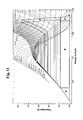
- FIG. 11 In the FIG. 11 In the T, s diagram for water, a circuit of a condensation circuit is compared with a back pressure circuit.
- An essential design criterion is the highest steam temperature (here 500 ° C). This has the consequence that the relaxation in the condensation cycle must be carried out with a higher entropy number than in the counter-pressure cycle.
- the back pressure circuit can be designed with a higher evaporation pressure (here 55 bar instead of 35 bar).
- the difference in efficiency and system performance can be judged by area size A and C and B.
- the area B In a combination of steam back pressure cycle and sorption cycle, the area B is converted into power almost equally by transfer of the heat of condensation to the sorption cycle.
- the effect of the feedwater heating up to the counter-pressure temperature through the surfaces D and D * is shown. Since the area size C is significantly larger than the area A (twice as large here), the combination has better efficiency than the condensation cycle.
- an absorption cycle (“AK") is designed to produce cold at a low temperature level.
- the in FIG. 9 illustrated main circuit to an absorption cycle extended. This is connected in parallel with the power generation.
- the first high pressure expeller (9) is extended to a HK / AK expeller (9a), the first solution heat exchanger (19a) to a solution heat exchanger (19e), the low pressure absorber (13) to a HK / AK low pressure absorber (13c).
- the HK / AK high-pressure steam (28e) expelled in the HK / AK generator (9a) is divided by means of a three-way valve (50) into a first partial flow of high-pressure steam (28a) and high-pressure steam (28b).
- the first partial flow of high-pressure steam (28a) is supplied to the superheater (30) and the AK high-pressure steam (28b) to an AK condenser (42) and liquefied there with the release of heat.
- the almost pure AK ammonia liquid (46) is fed to an AK liquid aftercooler (43) and cooled in countercurrent to the AK ammonia low-pressure steam (33c), then lowered to low pressure by means of an AK throttle (47) and then to an AK evaporator (44). fed.
- the AK ammonia liquid (46) evaporates while absorbing heat at a temperature level well below the ambient level.
- the AK ammonia low pressure steam (33c) is passed through the AK liquid aftercooler (43) and then sent to the HK / AK low pressure absorber (13c) for absorption as superheated AK ammonia low pressure steam (33d).
Abstract
Description
Die Erfindung betrifft ein Arbeitsverfahren eines Sorptionskraftzyklus in einer Sorptionsanlage für das Zweistoffgemisch Ammoniak und Wasser zur Erzeugung mechanischer Energie und/oder Kälteleistung aus mindestens einer externen Wärmequelle, vorzugsweise aus einer Niedertemperaturwärmequelle.The invention relates to a method of operation of a sorption cycle in a sorption plant for the two-substance mixture ammonia and water for generating mechanical energy and / or cooling capacity from at least one external heat source, preferably from a low-temperature heat source.
Aus einer Lösung von Ammoniak und Wasser Dampf auszutreiben und diesen zur Erzeugung mechanischer Energie zu entspannen, ist bekannt. Der entspannte Dampf wird im Unterschied zu Einstoffkreisläufen nicht kondensiert, sondern von Ammoniak/Wasser-Lösung absorbiert.From a solution of ammonia and water expel steam and this relax to generate mechanical energy is known. The expanded steam is not condensed, unlike single-material cycles, but absorbed by ammonia / water solution.
Zu den Kraftwerksprozessen, die Ammoniak und Wasser verwenden und die Entspannung eines Mischdampfes vorsehen, gehören die Kalina- Zyklen. Kalina hat in mehr als 20 Erfindungen Kraftwerkskreisläufe entwickelt, deren gemeinsames Merkmal die Verwendung von Ammoniak und Wasser ist. Für die Ausnutzung einer Wärmequelle mit einer Maximaltemperatur unterhalb von 200 °C ist der so bezeichnete Kreislauf KCS 34 nach Mlcak ("
Pall Valldimasson hat u.a. T-h Diagramme des binären Stoffpaares Ammoniak und Wasser mit unterschiedlichen Ammoniakanteilen veröffentlicht. Daraus geht u.a. hervor, dass Sattdämpfe bei einem Ammoniakgewichtsanteil von 95 % zwischen 10 und 70 bar den gleichen oder nahezu gleichen Enthalpiewert aufweisen, die Temperatur mit zunehmendem Druck hingegen höhere Werte annimmt. Die Enthalpiedifferenz zwischen Sattdampflinie zur Linie des Nassdampfes mit einem Dampfgehalt von 0,9 ist bei einem Ammoniakanteil von 0,95 besonders groß. Für das genannte binäre Zweistoffgemisch ergeben Berechnungen der Enthalpiedifferenz für die Entspannung eines Nassdampfes und Variation den Ausgangsdruck zwischen 10 und 70 bar: Bei gleichem Druckgefälle ist die Enthalpiedifferenz eines Dampfes mit gleichem Ammoniakanteil fast vollständig unabhängig vom Eingangsdruck und dessen Eingangstemperatur.Pall Valldimasson published Th diagrams of the binary substance pair ammonia and water with different proportions of ammonia. This shows, among other things, that saturated vapors with an ammonia weight fraction of 95% between 10 and 70 bar have the same or nearly the same enthalpy value, while the temperature increases with increasing pressure. The enthalpy difference between the saturated steam line and the wet steam line with a vapor content of 0.9 is particularly pronounced with an ammonia content of 0.95 large. For the binary binary mixture mentioned, calculations of the enthalpy difference for the relaxation of a wet steam and variation the output pressure between 10 and 70 bar: At the same pressure gradient, the enthalpy difference of a vapor with the same ammonia content is almost completely independent of the inlet pressure and its inlet temperature.
Es sind mehrere Kreisläufe für das binäre Stoffpaar Ammoniak und Wasser für die Erzeugung von mechanischer Energie bekannt, die entspannten Dampf nicht durch Kondensation sondern auf einem niedrigeren Druckniveau durch Absorption verflüssigen. Hierzu gehören die Kreisläufe
Die Kreisläufe nach
In
In
In
Binäre Gemische haben den thermodynamischen Vorteil, dass sie bei der Wärmeaufnahme eine stetig verlaufende Temperaturänderung erfahren. Die Wärmeaufnahme ist jedoch nicht linear. In
- Einem Hauptkreislauf wird ein Zusatzkreislauf hinzugefügt,
- Arbeitsmittel und Umlaufmenge in den Lösungen des Hauptkreislaufs bzw. des Zusatzkreislaufs werden von einander abweichend festgelegt,
- externe Wärmeenergie wird zur Dampfaustreibung im höheren Temperaturbereich an den Hauptkreislauf, im darunter liegenden Temperaturbereich an den Zusatzkreislauf übertragen,
- die Hochdruckdämpfe des Hauptkreislaufes und des Zusatzkreislaufes werden auf gleichem Druckniveau erzeugt,
- die Hochdruckdämpfe des Hauptkreislaufes und des Zusatzkreislaufes werden bezüglich der Anteile von Sorptionsmittel und Lösungsmittel angeglichen, wobei
- die Hochdruckdämpfe des Hauptkreislaufes und des Zusatzkreislaufes gemeinsam zur Erzeugung mechanischer Energie entspannt werden,
- das Druckniveau der Absorption wird im Zusatzkreislauf höher als im Hauptkreislauf festgelegt ist,
- Bei Rektifikation von Mischdämpfen wird freigesetzte Wärme an eine in den Rektifikator eingeleitete reiche Lösung übertragen und aus dieser Hochdruckdampf ausgetrieben und die verleibende Lösung aufgewärmt wird,
- Die Entspannung wird in Form von einem Entspannungsapparat oder einem Entspannungsapparat mit Dampfanzapfung vorgenommen, im letzteren Fall verknüpft mit einer Absorption des entspannten Dampfes auf zwei Druckstufen.
- A secondary circuit is added to a main circuit,
- Working fluid and circulating volume in the solutions of the main circuit and the additional circuit are set differently from each other,
- external heat energy is transferred to the main circuit for the expulsion of steam in the higher temperature range, in the lower temperature range to the additional circuit,
- the high-pressure vapors of the main circuit and the additional circuit are generated at the same pressure level,
- The high-pressure vapors of the main circuit and the additional circuit are adjusted with respect to the proportions of sorbent and solvent, wherein
- the high-pressure vapors of the main circuit and the additional circuit are expanded together to generate mechanical energy,
- the pressure level of the absorption is set higher in the additional cycle than in the main cycle,
- When rectifying mixed vapors, released heat is transferred to a rich solution introduced into the rectifier and expelled from this high-pressure steam and the remaining solution is warmed up,
- The relaxation is carried out in the form of an expansion apparatus or an expansion apparatus with steam tapping, in the latter case associated with absorption of the expanded steam to two pressure stages.
In
Die technisch zu lösende Aufgabe besteht darin, für die binären Stoffe Ammoniak und Wasser einen Sorptionskraftzyklus oder eine Kombination von Kraft-Zyklen zu entwickeln, mit denen unter Einsatz einer Wärmequelle relativ niedriger Temperatur der Wirkungsgrad der Anlage gegenüber dem Stand der Technik gesteigert wird.The technical problem to be solved is for the binary substances ammonia and Water to develop a Sorptionskraftzyklus or a combination of power cycles, which increases using a heat source of relatively low temperature, the efficiency of the system over the prior art.
Die Lösung der Aufgabe findet sich in einem Hauptanspruch und in weiteren zugeordneten Unteransprüchen.The solution of the problem can be found in a main claim and in further associated subclaims.
Kerngedanke der Erfindung ist, ein Arbeitsverfahren einer Sorptionsanlage mit dem binären Stoffpaar Ammoniak und Wasser so zu gestalten, dass zumindest im zweiten Teil der Entspannung die Taupunktlinie überschritten wird und der Entspannungsdampf einen energetisch optimalen Wassergewichtsanteil aufweist. Es werden hohe Leistungen erzielt bei vergleichsweise niedrigen Austreibertemperaturen. Dieser Kreislauf hat vorzugsweise einen definierten Wassergewichtsanteil von 3 bis 10 Gewichtsprozent vorzugsweise 6 %; bei einem Enddruck der Entspannung von 1,2 bis 4 bar, vorzugsweise von 1,5 bis 2 bar. Der Eingangsdruck beträgt mindestens 10 bar, vorzugsweise mindestens 13,5 bar. Der Dampfanteil wird am Entspannungsende oberhalb der Tropfenschlaggrenze eingestellt. Bei einem so ausgelegten Kreislauf wird an eine arme Lösung ein nicht unwesentlicher Teil der bei der Hochdruckaustreibung extern zugeführten Wärme übertragen. Diese kann zumindest teilweise intern zurückgewonnen werden, indem zur Hochdruckdampferzeugung Wärmeübertragung auch von der armen Lösung angeordnet wird. Die Entspannung kann sowohl in einem als auch in zwei hintereinander geschalteten Entspannungsapparaten erfolgen. Der Taupunkt wird im Entspannungsvollzug spätestens bei einem Druck von 9,5 bis 15 bar, vorzugsweise bei 13,5 bar überschritten, wobei die Taupunkttemperatur (entsprechend der Datenbank Refprop 8.0 des National Institute of Standards and Technology) zwischen 94,8 °C und 107,9 °C liegt. Der Kreislauf wird grundsätzlich so ausgelegt, dass die Hochdruckaustreibung aus einer Lösung beginnt, die bei dem genannten Druckniveau eine niedrigere Temperatur aufweist bzw. aufweisen würde und mit einer armen Lösung endet, die eine höhere Temperatur aufweist. Aufbauend auf dieser Basis wird bei Maximaltemperaturen der externen Wärmequelle über ca. 130 °C der Eingangsdruck zunehmend angehoben. Bei Anordnung nur eines einzigen Entspannungsapparats wird auch die Überhitzungstemperatur zunehmend angehoben. Hierbei wird ausgenutzt, dass die Taupunkttemperatur des Entspannungsdampfes deutlich unterhalb der Maximaltemperatur der Wärmequelle liegt, so dass der ausgetriebene Dampf überhitzt werden kann, gegebenenfalls über mehrere Zehner Kelvin. Der Wassergewichtsanteil im zu entspannenden Dampf wird grundsätzlich auf das energetische Optimum ausgerichtet und grundsätzlich nicht durch Gleichgewichtslinien am Ende oder Anfang der gesamten Hochdruckaustreibung bestimmt.The core idea of the invention is to design a working method of a sorption plant with the binary substance pair ammonia and water so that the dew point line is exceeded at least in the second part of the expansion and the expansion steam has an energetically optimal water weight fraction. High performances are achieved at comparatively low expeller temperatures. This cycle preferably has a defined water weight fraction of 3 to 10% by weight, preferably 6%; at a final pressure of relaxation of 1.2 to 4 bar, preferably from 1.5 to 2 bar. The inlet pressure is at least 10 bar, preferably at least 13.5 bar. The vapor content is set at the decompression end above the drop impact limit. With such a circuit, a not insubstantial part of the heat externally supplied during the high-pressure expulsion is transmitted to a poor solution. This can be at least partially recovered internally by heat transfer is also arranged by the poor solution for high pressure steam generation. The relaxation can be done both in one and in two successive relaxation apparatuses. The dew point is exceeded at the latest at a pressure of 9.5 to 15 bar, preferably 13.5 bar in the depressurization, the dew point temperature (according to the database Refprop 8.0 of the National Institute of Standards and Technology) between 94.8 ° C and 107 , 9 ° C is. The circulation is basically designed so that the high-pressure expulsion starts from a solution which has or would have a lower temperature at said pressure level and ends with a poor solution having a higher temperature. Building on this basis, the inlet pressure is increasingly raised above 130 ° C at maximum temperatures of the external heat source. If only a single expansion apparatus is arranged, the superheating temperature is also increasingly raised. This exploits that the dew point temperature of the flash steam is well below the maximum temperature of the heat source, so that the expelled steam can be overheated, possibly over several tens of Kelvin. The proportion of water in the steam to be relaxed is always aligned with the energy optimum and is not determined by equilibrium lines at the end or beginning of the entire high-pressure expulsion.
Kann die externe Wärmequelle über einen größeren Temperaturbereich ausgenutzt werden, findet die Absorption in bis zu drei Druckstufen statt. Ist die externe Wärmequelle zusätzlich tiefer als 60 bis 80 Kelvin oberhalb der Umgebungstemperatur ausnutzbar, wird ein Zusatzkreislauf angeordnet. Mit dieser Anordnung wird mittels des Prinzips der zweimaligen Wärmezufuhr für einen Teil des Hochdruckdampfes das Druckverhältnis bei der Entspannung vergrößert.If the external heat source can be utilized over a larger temperature range, the absorption takes place in up to three pressure stages. Is the external heat source additional deeper than 60 to 80 Kelvin above the ambient temperature ausnutzbar, an additional circuit is arranged. With this arrangement, by means of the principle of the two-time heat supply for a part of the high-pressure steam, the pressure ratio in the expansion is increased.
Zur Entspannung des beschriebenen Hochdruckdampfes können entweder ein Entspannungsapparat ohne Dampfanzapfung oder ein Entspannungsapparat mit Dampfanzapfung oder zwei Entspannungsapparate hintereinander geschaltete angeordnet werden.To relax the high-pressure steam described, either an expansion apparatus without steam tapping or a steam expansion apparatus or two expansion apparatuses can be arranged in series.
Zur Austreibung sind in der Sorptionskältetechnik Apparate in Nutzung, bei denen der Wasseranteil des ausgetriebenen Dampfes entweder im Gleichgewichtspunkt zur eintretenden oder zur austretenden Lösung steht. Nur in wenigen Anwendungsfällen wird mit einem der beiden Apparate ein Wassergewichtsanteil von ca. 6 % eintreten. Um das Ziel zu erreichen, wird erfindungsgemäß ein Verfahrensweg bei Erzeugung und Einstellung des Entspannungsdampfes vorgenommen, wobei zumindest eins der vier folgenden spezifischen Verfahrensmerkmale eingestellt sind:
- a) mindestens in einem Apparat Hochdruckdampf im Gleichgewichtspunkt zur eintretenden Lösung und in mindestens einem Apparat Hochdruckdampf im Gleichgewichtspunkt zur austretenden Lösung erzeugt wird,
- b) der Wassergewichtsanteil des Hochdruckdampfes in einem Rektifikator oder einer Destillationssäule festgelegt wird, wobei diese beiden Apparate auf eine Teilrektifikation ausgelegt sind,
- c) der Wassergewichtsanteil des Hochdruckdampfes auch durch eine eintretende Lösung festgelegt wird, die auf einem höheren Wasseranteil als die reichen Lösung (2) eingestellt ist,
- d) der Wassergewichtsanteil des Hochdruckdampfes durch Zuleitung und Verdampfung von Lösung in den Überhitzer eingestellt wird.
- a) at least in one apparatus, high-pressure steam at the point of equilibrium to the incoming solution and in at least one apparatus high-pressure steam at the point of equilibrium with the exiting solution is produced,
- b) the water weight fraction of the high-pressure steam is determined in a rectifier or a distillation column, these two apparatuses being designed for a partial rectification,
- c) the water weight fraction of the high-pressure steam is also determined by an incoming solution, which is adjusted to a higher water content than the rich solution (2),
- d) the proportion by weight of water of the high-pressure steam is set by supplying and evaporating solution into the superheater.
Das Verfahrensmerkmal c) ist in den Darstellungen in den
Hauptmerkmal der zweiten Gruppe ist, dass der höchste Temperaturbereich der externen Wärmequelle durch einen Hochdruckaustreiber ausgenutzt wird, der nach dem Rieselprinzip arbeitet und der nächst tiefere Temperaturbereich durch einen oder zwei Hochdruckaustreiber ausgenutzt wird, der oder die nach dem Blasenprinzip arbeiten (Darstellungen in den
Weist die externe Wärmequelle ein großes Temperaturgefälle auf, wird die arme Lösung im Hochtemperaturbereich zumindest überwiegend zur Hochdruckaustreibung eingesetzt. Im Unterschied zu
Wenn eine externe Wärmequelle über eine große Temperaturspanne ausgenutzt werden kann, so ist zudem die Anordnung von drei Absorptionsstufen energetisch optimal. Durch Anordnung eines Entspannungsapparates mit Dampfentnahme und hintereinander angeordneten Hochdruckaustreiber(n) mit Gleichgewichtslinie des Dampfes zuerst zur eintretenden Lösung und nachgeschaltet zur austretenden Lösung entsprechend
Potentiell weist die Schaltung mit zwei hintereinander geschalteten Entspannungsapparaten einen besonderen Vorteil auf: Bekanntermaßen wird die Leistung von Stromerzeugungsanlagen, die von einer Wärmequelle niedriger Temperatur beheizt werden, erheblich von den Kühlungstemperaturen beeinflusst. Dass sie an die Umgebungstemperatur gekoppelt sind, ist an vielen potentiellen Einsatzorten anzunehmen. In vielen Klimaten schwankt die Umgebungstemperatur stark. Es ist möglich, diese Schwankungen nur oder weitgehend auf den Mitteldruckentspannungsapparat zu konzentrieren und den Hochdruckentspannungsapparat entsprechend von diesen Schwankungen freizuhalten. Weist die externe Wärmequelle zudem eine weitgehend gleichmäßige Wärmelieferung auf, so ist eine Steigerung des inneren Wirkungsgrades des Hochdruckentspannungsapparates entsprechend der Fahrweise auf einen Bestpunkt potentiell möglich.Potentially the circuit has two sequential relaxation apparatuses a special advantage: As is known, the power of power plants, which are heated by a heat source low temperature, significantly influenced by the cooling temperatures. That they are coupled to the ambient temperature, is to be adopted at many potential sites. In many climates, the ambient temperature varies greatly. It is possible to concentrate these fluctuations only or largely on the medium-pressure expansion apparatus and to keep the high-pressure expansion apparatus accordingly free of these fluctuations. If the external heat source also has a largely uniform heat supply, an increase in the internal efficiency of the high-pressure relaxation apparatus according to the driving style to a best point is potentially possible.
Die Entspannung nur mit einem Entspannungsapparat ohne Dampfanzapfung auszuführen, ist bei Temperaturquellen mit verhältnismäßig geringen ausnutzbaren Temperaturspanne der Wärmequelle die beste Lösung. Kann die Wärmequelle über eine größere Temperaturspanne ausgenutzt werden, ist das Prinzip der zweimaligen Wärmezufuhr in der beschriebenen Form notwendig. Es ist nur die Anordnung von zwei Absorptionsdruckstufen möglich. Im Vergleich zu dieser Anordnung ergeben andere Anordnungen wie diejenige eines Entspannungsapparates mit einer Dampfentnahme oder diejenige von zwei hintereinander geschalteten Entspannungsapparaten höhere Anlagenleistungen.Performing the relaxation only with a relaxation apparatus without Dampfanzapfung is the best solution for temperature sources with relatively low usable temperature range of the heat source. If the heat source can be used over a larger temperature range, the principle of the two-time heat supply in the form described is necessary. Only the arrangement of two absorption pressure stages is possible. Compared to this arrangement, other arrangements such as that of a flash-off apparatus with a steam extraction or that of two successive relaxation apparatuses give higher plant performance.
Ist eine Wärmequelle auszunutzen, deren Maximaltemperatur deutlich oberhalb der Einsatzgrenze des binären Stoffes Ammoniak/Wasser liegt, so ist folgende Anordnung vorzusehen: In einem Clausius-Rankine-Kreislauf mit dem Einstoffmedium Wasser wird Wasserdampf in einer Gegendruckturbine nur teilentspannt. Der Gegendruckdampf wird dem Sorptionskraftzyklus zugeleitet. Für diesen ist der kondensierende Wasserdampf als externe Wärmequelle angeordnet. Im folgenden ist eine solche Wärmequelle jeweils von einer Niedertemperaturwärmequelle zu unterscheiden. Eine entsprechende Wärmeübertragung ist zur Kälteerzeugung mit dem binären Stoff Ammoniak/Wasser weitverbreitet. Entsprechend der Darstellung der
Die Wärmeübertragung kann auch auf zwei Temperaturstufen erfolgen, indem der Gegendruckturbine ein Dampfstrom auf höherem Temperaturniveau entnommen und dem Sorptions-Kraft-Zyklus zugeleitet wird.The heat transfer can also be carried out at two temperature levels, by the back pressure turbine, a vapor stream is taken at a higher temperature level and fed to the sorption-force cycle.
Hauptunterschiede der Kreislaufauslegung und Leistungsunterschiede zwischen der Erfindung und Kalina-Prozeß KCS 34 werden an Hand folgenden Beispiels erläutert. Im Vergleichsbeispiel beträgt die Maximaltemperatur der Wärmequelle 150 °C. Die Austreibung wird in beiden Kreisläufen so ausgelegt, dass der Entspannungsdampf einen Wassergewichtsanteil von 6 % aufweist. Im Vergleich wird auf die Wärmezufuhr zur Aufwärmung der Hochdruckaustreibung zugeleiteten Lösung(en) verzichtet. Es wird unterstellt, dass unterhalb des Temperaturniveaus der Hochdruckaustreibung genügend Wärme von armer Lösung und Wärmequelle bereit gestellt werden kann.Major differences in circuit design and performance differences between the invention and
Der Kalina-Prozeß KCS 34 arbeitet mit dem gleichen Zweistoffgemisch Ammoniak und Wasser wie die Erfindung. Im Kalina-Kreislauf KCS 34 beginnt die (Hochdruck-)Austreibung aus einer reichen Lösung mit einem Ammoniakgewichtsanteil von 0,83 bei 85,6 °C. Es wird ein Zweiphasengemisch erzeugt und im Separator entsprechend einem Druck von 37,5 bar und einer Temperatur von 136,4 °C ein Dampf von der armen Lösung getrennt und ohne Überhitzung dem Entspannungsapparat zugeleitet. Der Dampf wird mit einem Druckverhältnis von 5 von 37,5 bar bis 7,5 bar und 68,7 °C entspannt und bei einer minimalen Lösungstemperatur von 21,8 °C absorbiert. Im KCS 34 wird die ammoniakarme Lösung nach der Desorption nicht zur Austreibung herangezogen, sondern nur Lösungsaufwärmung der reichen Lösung verwendet. Hierzu wird ebenfalls ein Teil der Absorptionswärme herangezogen. Ein Teil der Absorptionswärme wird genutzt, um die reiche Lösung aufzuwärmen.The
Für den vorgestellten erfindungsgemäßen Kreislauf wird ein gleiches Druckverhältnis wie für den Kalina-Prozeß KCS 34 angesetzt. Es wird ein Kreislauf nach
Dem Zyklus der vorliegenden Erfindung wird mehr Wärme aus der Wärmequelle zur Hochdruckaustreibung zugeführt, im Kalina-Kreislauf wird dem Hochdruckaustreiber eine höher aufgewärmte reiche Lösung zugeführt und eine erheblich geringere Menge armer Lösung abgeleitet. In der vorliegenden Erfindung wird die arme Lösung zur Hochdruckaustreibung zum Zweck der Wärmerückgewinnung herangezogen (siehe Zeile 4 und 5 in folgender Tabelle). Dadurch wird 18 % der Wärme zur Hochdruckaustreibung und Überhitzung bereitgestellt.The cycle of the present invention is supplied with more heat from the heat source for high pressure expulsion, in the Kalina cycle the high pressure expeller is fed a higher heated rich solution and a significantly lower amount of poor solution is discharged. In the present invention, the poor solution is used for high-pressure expulsion for the purpose of heat recovery (see
Unabhängig von der Temperatur weisen die Sattdämpfe beider Kreisläufe eine nahezu gleiche spezifische Wärme auf: Die spezifische Entspannungsleistung durch die Überhitzung liegt in der vorliegenden Erfindung um 3,7 % höher. Auf Grund der geringen Unterschiede wird der Vergleich auf die produzierte Dampfmenge und das Entspannungsverhältnis beschränkt. Hierbei wird unterstellt, dass im Temperaturbereich unterhalb der Hochdruckaustreibung arme Lösung, Wärmequelle und (nur im Kalina-Kreislauf) Wärmerückgewinnung aus dem entspannten Dampf genügend Wärme bereitstellen, um die reiche Lösung bis zur Siedetemperatur aufzuwärmen. Der innere Wirkungsgrad der Entspannungsapparate ist jeweils auf 85 % angesetzt.Regardless of the temperature, the saturated vapors of both circuits have nearly the same specific heat: the specific superheat relaxation performance in the present invention is 3.7% higher. Due to the small differences, the comparison is limited to the amount of steam produced and the expansion ratio. It is assumed that in the temperature range below the high-pressure expulsion, poor solution, heat source and (only in the Kalina cycle) heat recovery from the expanded steam provide enough heat to warm the rich solution up to the boiling point. The internal efficiency of the expansion apparatus is set at 85%.
Unter diesen Annahmen ergibt sich folgende Bilanz der Hochdruckaustreibung und der Anlagenleistung:
Der Kalina-Kreislauf wäre einem Sorptionskraftzyklus, der mit einem Absorber und einer Wassergewichtsanteil des Entspannungsdampfes von 96 % ausgelegt ist, energetisch vorzuziehen. Der Zyklus der vorliegenden Erfindung enthält daher vier leistungssteigernde Verfahrensmerkmale.The Kalina cycle would be energetically preferable to a sorptive cycle designed with an absorber and a water weight fraction of 96% flash steam. The cycle of the present invention therefore includes four performance enhancing process features.
Das erste leistungssteigernde Verfahrensmerkmal der vorliegenden Erfindung ist die Absorption auf einer zweiten Druckstufen, um zumindest einen Teil des Dampfes weiter zu entspannen (
Als zweites leistungssteigerndes Verfahrensmerkmall wird in der vorliegenden Erfindung entsprechend dem beschriebenen Prinzip der zweimaligen Wärmezufuhr mittels eines Zusatzkreislaufes eine größere Dampfmenge von Hochdruck (4 bar) auf Niederdruck (1,5 bar) entspannt. (Hochdruckaustreibung nach
Als drittes leistungssteigerndes Verfahrensmerkmal wird eine dritte Absorptionsstufe bei 2,664 bar eingefügt. Auf diesem Druckniveau wird der Entnahmedampf ausgekoppelt. Es wird mit einmaliger Wärmezufuhr 3,661 kg/s des Hochdruckdampfes bis auf 1,5 bar und 5,804 kg/s auf 3 bar, mit zweimaliger Wärmezufuhr 7,187 kg/s auf 1,5 bar entspannt werden. Die Summe des Hochdruckdampfes bleibt mit 17,281 kg/s unverändert (Hochdruckaustreibung nach
In der Bilanz zur Hochdruckaustreibung ändert sich nur die letzte Zeile:
Im vierten leistungssteigernden Verfahrensmerkmal wird im Unterschied zum dritten leistungssteigernden Verfahrensmerkmal angereicherte Lösung aus dem Absorber mit der niedrigsten Druckstufe in den Rektifikator geleitet (
Es ergibt sich folgende Bilanz
In dem fünften leistungssteigernden Verfahrensmerkmal wird die durch das vierte leistungssteigernde Verfahrensmerkmal bewirkte Reduzierung der Menge der reichen Lösung zu einer verstärkten Ausnutzung der externen Wärmequelle im Hochdruckaustreiber ausgenutzt. (Absorption und Hochdruckaustreibung nach
Es ergibt sich folgende Bilanz
Bezüglich des Pumpstromaufwandes besteht zwischen Kalina-Kreislauf KCS 34 und der vorliegenden Erfindung kein merklicher Unterschied: Das Produkt aus Menge der reichen Lösung mal Druckdifferenz ist annähernd gleich.With respect to the pumping power, there is no significant difference between
An Hand des gewählten Beispiels einer Wärmequelle mit einer Maximaltemperatur von 150 °C wird gezeigt, dass gegenüber dem Kalina-Kreislauf mit dem der vorliegenden Erfindung maximal 36 % mehr Leistung möglich ist. Unterscheidet sich die Maximaltemperatur der Wärmequelle von der im Beispiel angesetzten 150 °C, so kann in der vorliegenden Erfindung ebenfalls auf die beschriebene energetisch optimale Zusammensetzung des Entspannungsdampfs ausgelegt werden. Das ist im Kalina-Kreislauf nicht der Fall. Der Wasseranteil im Entspannungsdampf weicht von dem optimalen Anteil von ca. 0,96 ab. Dies ist insbesondere bei höheren Maximaltemperaturen der Wärmequelle der Fall, anderseits nimmt der Leistungsvorteil der vorliegenden Erfindung, der auf der tieferen Auskühlung der Wärmequelle beruht, nur absolut zu, relativ jedoch ab.On the basis of the selected example of a heat source with a maximum temperature of 150 ° C is shown that compared to the Kalina cycle with the present invention, a maximum of 36% more power is possible. If the maximum temperature of the heat source differs from the 150 ° C. used in the example, it is likewise possible in the present invention to be designed for the described energetically optimum composition of the flash vapor. This is not the case in the Kalina cycle. The water content in the flash vapor deviates from the optimum proportion of about 0.96. This is the case in particular at higher maximum temperatures of the heat source, on the other hand, the power advantage of the present invention, which is based on the deeper cooling of the heat source, only to absolute, but relative decreases.
Eine energetische Überlegenheit gegenüber dem Kalina KCS 34 ist für die vorliegende Erfindung gegeben, selbst wenn nur das erste leistungssteigernde Verfahrensmerkmal der vorliegenden Erfindung angeordnet wird, wie der Zyklus bei entsprechend ausgelegter Kraft-Wärmenutzung angewendet werden kann.An energetic superiority over the
Sowohl das zweite und dritte als auch das vierte und fünfte leistungssteigernde Verfahrensmerkmal erhöhen die Wärmezufuhr an die Anlage: Hierbei ist der Wirkungsgrad der beiden letztgenannten etwa doppelt so hoch wie der beiden erstgenannten. Kann eine Wärmequelle nur begrenzt ausgekühlt werden, so ist der Fortfall des Zusatzkreislaufes - also des zweiten und dritten leistungssteigernden Verfahrensmerkmals - dann vorzuziehen, wenn zwei Dampfentnahmen aus dem Entspannungsapparat und dem mittleren und höchsten Absorptionsdruck vorgenommen werdenBoth the second and third and the fourth and fifth performance-enhancing process feature increase the heat input to the system: Here, the efficiency of the latter two is about twice as high as the first two. If a heat source can only be cooled to a limited extent, the elimination of the additional cycle - ie the second and third performance-enhancing process feature - is preferable when two steam withdrawals from the flash apparatus and the medium and highest absorption pressure are made
Schaltungen mit Zusatzkreislauf, in denen zur Hochdruckdampferzeugung nicht nur reiche Lösung, sondern auch angereicherte Lösung zugeleitet wird, sind dann energetisch vorteilhaft, wenn eine vergleichsweise geringe Menge reicher Lösung umläuft. Im Bereich der genannten zweimaligen Wärmezufuhr wird unter dieser Bedingung weniger Wärme zu Austreibung im Zusatz-Mitteldruckaustreiber benötigt, entsprechend mehr Wärme steht zu Hochdruckaustreibung zur Verfügung und eine größere Menge an Entspannungsdampf wird produziert. Noch größer ist der diesbezügliche Vorteil zu Kreisläufe, in denen nahezu reiner Ammoniakdampf erzeugt wird: Deren ausgetriebenen Dämpfe weisen eine geringere Enthalpie auf und damit höheren Umlaufwerte, gleichbedeutend höhere Mengen reicher Lösung.Circuits with additional circuit in which not only rich solution, but also enriched solution is fed to the high-pressure steam generation, are then energetically advantageous when a relatively small amount of rich solution rotates. In the case of the aforementioned two-fold heat supply under this condition, less heat is required for expulsion in the additional medium-pressure compressor, correspondingly more heat is available for high pressure expulsion and a larger amount of flash steam is produced. Even greater is the relative advantage to cycles in which produces almost pure ammonia vapor Their exhaled vapors have a lower enthalpy and thus higher circulation values, equivalent to higher amounts of rich solution.
Die bezügliche Leistungsminderung beträgt ca. 4 % in einem Kreislauf, der die fünf leistungssteigernden Verfahrensmerkmale grundsätzlich enthält, aber auf die Entspannung überhitzten nahezu reinen Ammoniakdampf ausgelegt ist. Weitere ca. 5 % Leistungsminderung sind auf geringere Enthalpiedifferenzen im Entspannungsvorgang zurückzuführen.The related performance reduction is about 4% in a cycle that basically contains the five performance-enhancing process features, but designed for the relaxation overheated almost pure ammonia vapor. A further reduction of about 5% is due to lower enthalpy differences in the expansion process.
Im folgenden wird die Nutzung von Wasserdampf in einem Sorptionskraftzyklus oder in einer (Wasserdampf-)Niederdruckturbine verglichen. Der Wasserdampf hat eine Temperatur von 150° C und einen Druck von 1,98 bar. Das Speisewasser wird auf 150° C aufgewärmt..
Die Vergleichsrechnung zeigt, dass bei dieser Temperatur die Niederdruckturbine wenige Prozent höhere Leistung abgibt. Diese ist auch auf den angesetzten höheren inneren Wirkungsgrad der Wasserdampfturbine zu Beginn der Entspannung in der Niederdruckturbine (89%) im Vergleich zum Entspannungsapparat des Sorptionskraftzyklus (85%) begründet.The comparative calculation shows that at this temperature, the low-pressure turbine delivers a few percent higher performance. This is also due to the assumed higher internal efficiency of the steam turbine at the beginning of the relaxation in the low-pressure turbine (89%) compared to the relaxation apparatus of the sorption cycle (85%).
Bei dieser Nutzung einer Wärmequelle mit konstanter Temperatur kann der Sorptionskraftzyklus mit wenigen Apparaten errichtet und der Lösungskreislauf analog zum bekannten Sorptionskreislauf zur Kälteerzeugung ausgeführt werden.With this use of a constant temperature heat source, the sorption cycle can be established with a few apparatuses and the solution cycle can be carried out analogously to the known refrigeration sorption cycle.
Für die Wärmeübertragung von der armen Lösung zur Austreibung ist in der vorliegenden Erfindung mittels einem einzigen Apparat statt zu den in
Soweit in der vorliegenden Erfindung ein Überhitzer für den Entspannungsdampf angeordnet ist, liegt dessen Eintrittstemperatur deutlich höher als bei Kreisläufen, die eine Überhitzung eines nahezu reinen Ammoniakdampfes vorsehen und die Austrittstemperatur kann ohne wesentliche thermodynamische Nachteile in einem größeren Abstand zur Maximaltemperatur der Wärmequelle beendet werden. Der Bauaufwand für den Überhitzer fällt entsprechend kleiner aus.As far as in the present invention, a superheater is arranged for the flash vapor, its inlet temperature is significantly higher than in circuits that provide overheating of an almost pure ammonia vapor and the outlet temperature can be terminated without significant thermodynamic disadvantages at a greater distance to the maximum temperature of the heat source. The construction costs for the superheater is correspondingly smaller.
Ohne Leistungsnachteile kann der niedrigste Absorptionsdruck oberhalb des Umgebungsdruckes angeordnet werden, womit eingedrungene Luft aus dem Lösungskreislauf nicht entfernt werden muss und gleichzeitig der Bereich hoher Unterkühlungstemperaturen im Absorptionsprozess gemieden wird.Without sacrificing performance, the lowest absorption pressure can be located above ambient, eliminating the need to remove any entrained air from the solution loop while avoiding the region of high subcooling temperatures in the absorption process.
Da keine Wärme aus einem angeordneten Rektifikator zur Aufwärmung der reichen Lösung übertragen wird, wird die arme Lösung in den meisten Auslegungsfällen stark unterkühlt in den Absorber mit dem niedrigsten Temperaturniveau eintreten. Gleichfalls tritt die Lösung in die folgenden Absorber stark unterkühlt ein. Zu Beginn des Absorptionsprozesses wird die Lösung jeweils aufgewärmt und die anfallende Sorptionswärme nicht nach außen an das Kühlmedium übertragen. Dies senkt den diesbezüglichen spezifischen Bauaufwand eines in der Regel notwendigen Rückkühlturmes um 10 bis 15 % im Vergleich zu Anlagen der Sorptionstechnik.Since no heat is transferred from an arranged rectifier to warm the rich solution, the poor solution will be highly undercooled in most design cases, entering the absorber with the lowest temperature level. Likewise, the solution enters the following absorber strongly undercooled. At the beginning of the absorption process, the solution is warmed up in each case and the resulting heat of sorption is not transferred to the outside to the cooling medium. This lowers the related specific construction cost of a generally required back-cooling tower by 10 to 15% compared to systems of sorption.
Bei größeren Anlagen werden nach dem Stand der Technik Absorber eingesetzt, die nach dem Rieselprinzip arbeiten. Bei diesen nimmt der Wärmeübergang mit der Rieselstärke zu. Im Falle einer Anordnung eines Hauptkreislaufes und eines Zusatzkreislaufes wird in der ersten oder den ersten beiden Absorptionsstufen eine größere Rieselmenge und eine größere Dampfmenge im Vergleich zu einem Kreislauf ohne Zusatzkreislauf absorbiert. Die größere Rieselmenge begünstigt eine Apparateanordnung mit hohen Riesellängen und damit erhöhten Rieselstärken wie Turmabsorber oder die von mehreren übereinander angeordnet liegenden Rieselabsorbern.In larger systems, absorbers are used according to the prior art, which operate on the trickle principle. In these, the heat transfer increases with the Rieselstärke. In the case of an arrangement of a main circuit and an additional circuit, a larger amount of trickle and a larger amount of steam is absorbed in the first or the first two absorption stages compared to a circuit without additional circuit. The larger amount of trickle favors an apparatus arrangement with high trickle lengths and thus increased Rieselstärken as tower absorber or of several stacked Rieselabsorbern.
Mittels der Anordnung eines Mitteldruckabsorbers der unteren Druckstufe ohne Wärmeabfuhr können gegebenenfalls die Baukosten zusätzlich gesenkt werden. Die Entgasungsbreite eines solchen eingefügten Absorbers ist relativ gering. Diese Schaltungsanordnung kann bevorzugt bei nicht sehr hohen Maximaltemperaturen der externen Wärmequelle angewandt werden, da dann keine sehr große Entgasungsbreite der Summe aller drei Absorber geboten ist.By means of the arrangement of a medium-pressure absorber of the lower pressure stage without heat dissipation, the construction costs can optionally be further reduced. The degassing width of such an inserted absorber is relatively low. This circuit may preferably be applied at not very high maximum temperatures of the external heat source, because then no very large Entgasungsbreite the sum of all three absorbers is required.
Der leistungssteigernde Effekt der Dampfentnahme ist in der vorliegenden Erfindung deutlich höher als derjenige zu einer Stufe der Speisewasseraufwärmung einer Wasserdampfturbine. Mehrere Entnahmen sind in der vorliegenden Erfindung wenig sinnvoll.The efficiency-increasing effect of the steam extraction is significantly higher in the present invention than that to a stage of the feedwater heating of a steam turbine. Multiple withdrawals make little sense in the present invention.
Kann der Dampf durch eine zweite Wärmequelle beheizt und noch höher überhitzt werden, so ist es zweckmäßig parallel zu der steigenden Dampftemperatur den Enddruck wieder abzusenken bis zu dem maximal vertretbaren Druck von 1,2 bar. Diese Vorgehensweise ist bei niedrigeren Maximaltemperatur einer ersten externen Wärmequelle mit großer Wärmekapazität und einer zweiten Wärmequelle mit höherer Maximaltemperatur und geringer Wärmekapazität sehr attraktiv. In solchen Fällen wird die Überhitzung des Dampfes von der zweiten Wärmequelle vorgenommen. Die spezifische Leistung pro kg Dampf steigt erheblich und damit die Anlagenleistung (z. B. um fast ein Viertel, wenn die Dampftemperatur um ca. 30 Kelvin höher als die erste Wärmequelle liegt). Die Kombination mit der vorher beschriebenen Dampfentnahme führt in vielen Anwendungsfällen zu einer Anlagensteigerung.If the steam can be heated by a second heat source and heated even higher, it is expedient to lower the final pressure parallel to the rising steam temperature again up to the maximum acceptable pressure of 1.2 bar. This approach is very attractive at lower maximum temperature of a first external heat source with high heat capacity and a second heat source with higher maximum temperature and low heat capacity. In such cases, the overheating of the steam is done by the second heat source. The specific power per kg of steam increases considerably, and thus the system output (for example, by almost a quarter, when the steam temperature is about 30 Kelvin higher than the first heat source). The combination with the previously described steam extraction leads in many applications to a plant increase.
Im folgenden werden bevorzugte Ausführungsformen der Erfindung an Hand von Zeichnungen erläutert. Es werden 11 Figuren beigefügt,In the following preferred embodiments of the invention will be explained with reference to drawings. 11 figures are attached,
Die
-
Fig. 1 : mit einem Riesel- und zwei Blasen-Hochdruckaustreibern, 1 Absorber und einem Entspannungsapparat, -
Fig. 2 : mit zwei Blasen-Hochdruckaustreibern, 1 Absorber und einem Entspannungsapparat -
Fig. 3 : mit einem Riesel- und zwei Blasen-Hochdruckaustreibern, 2 Absorbern und einem Entspannungsapparat mit einer Dampfentnahme, -
Fig. 4 : mit einem Riesel- und einem Blasen-Hochdruckaustreiber, 2 Absorbern, einem Entspannungsapparat und Zusatzkreislauf, -
Fig. 5 : mit einem Riesel- und zwei Blasen-Hochdruckaustreibern, 3 Absorbern, einem Entspannungsapparat mit einer Dampfentnahme und Zusatzkreislauf, -
Fig. 6 : mit zwei Blasen-Hochdruckaustreibern, 3 Absorbern, einem Entspannungsapparat mit einer Dampfentnahme und Zusatzkreislauf, -
Fig. 7 : mit einem Riesel- und zwei Blasen-Hochdruckaustreibern, 3 Absorbern, zwei Entspannungsapparaten, einem Zwischenüberhitzer und Zusatzkreislauf, -
Fig. 8 : mit zwei Blasen-Hochdruckaustreibern einer Destillationssäule, 3 Absorbern, zwei Entspannungsapparaten, einem Zwischenüberhitzer und Zusatzkreislauf, -
Fig. 9 : mit Gegendruckdampf als externe Wärmequelle, -
Fig. 10 : mit Gegendruckdampf als externe Wärmequelle und drei Riesel-Hochdruckaustreibern, -
Fig. 11 : zum Sorptionskraftzyklus vorgeschaltete Gegendruckturbine im Vergleich zur Kondensationsturbine im T,s-Diagramm und -
Fig. 12 : entsprichtFig. 9 mit Gegendruckdampf als externe Wärmequelle mit parallel geschalteter Kälteanlage.
-
Fig. 1 with one trickle and two bubble high-pressure exhausters, 1 absorber and a relaxation apparatus, -
Fig. 2 : with two high-pressure bubble exhausters, 1 absorber and a relaxation apparatus -
Fig. 3 with one trickle and two blast high pressure exhausters, 2 absorbers and a flash-off apparatus with a steam extraction, -
Fig. 4 with a trickle and a bubble high-pressure expander, 2 absorbers, a relaxation apparatus and auxiliary circuit, -
Fig. 5 with one trickle and two bubble high-pressure exhausts, 3 absorbers, one expansion device with a steam extraction and additional cycle, -
Fig. 6 : with two high-pressure bubble ejectors, 3 absorbers, one expansion unit with a steam extraction and additional circuit, -
Fig. 7 with one trickle and two bubble high-pressure exhausters, 3 absorbers, two expansion devices, a reheater and auxiliary circuit, -
Fig. 8 with two high-pressure bubble ejectors of a distillation column, 3 absorbers, two expansion apparatus, a reheater and auxiliary circuit, -
Fig. 9 with backpressure steam as external heat source, -
Fig. 10 : with back pressure steam as external heat source and three Riesel high pressure exhausts, -
Fig. 11 : upstream of the sorption cycle backpressure turbine compared to the condensing turbine in the T, s diagram and -
Fig. 12 : correspondsFig. 9 with back pressure steam as an external heat source with a parallel-connected refrigeration system.
In der
Entspannter Mitteldruckdampf (32) wird von dem Hochdruckentspannungsapparat (31) einem unter nahezu demselben Druck stehenden Mitteldruckabsorber (14) zugeleitet. Das Druckniveau wird hier mit Mitteldruck bezeichnet. Im Mitteldruckabsorber (14) wird der Mitteldruckdampf (32) unter Wärmeabgabe von der armen Lösung (8) (arm an Arbeitsmittel) absorbiert. Die abzuführende Wärme wird an ein Kühlmedium übertragen. Hierfür wird bei dem Zweistoffgemisch Wasser und Ammoniak in der Regel Kühlwasser verwendet. Der Kühlkreislauf ist hier und in den folgenden Figuren nicht dargestellt. Die arme Lösung wird von einem ersten Hochdruckaustreiber (9) über einen ersten Lösungswärmetauscher (19a) zugeleitet. Vor der Absorption wird die arme Lösung (8) mittels der ersten Drossel (16a) von Hochdruckniveau auf Absorberdruck abgesenkt.Relaxed medium-pressure steam (32) is supplied from the high-pressure relaxation apparatus (31) to a medium-pressure absorber (14) which is under almost the same pressure. The pressure level is referred to here as medium pressure. In the medium-pressure absorber (14), the medium-pressure steam (32) is absorbed with heat release from the poor solution (8) (poor in working fluid). The dissipated heat is transferred to a cooling medium. For this purpose, water and ammonia are usually used in the dual-substance mixture cooling water. The cooling circuit is not shown here and in the following figures. The poor solution is supplied from a first high pressure expeller (9) via a first solution heat exchanger (19a). Prior to absorption, the poor solution (8) is lowered from the high pressure level to the absorber pressure by means of the first throttle (16a).
Durch die Absorption entsteht eine reiche Lösung (2). Die reiche Lösung (2) wird mittels einer ersten Lösungspumpe (10) auf das Druckniveau der Hochdruckaustreiber gebracht. Die reiche Lösung (2) wird über den Weg eines ersten Lösungswärmetauschers (19a) zu den zweiten und dritten Hochdruckaustreibern (3, 3a) geleitet.The absorption creates a rich solution (2). The rich solution (2) is brought by means of a first solution pump (10) to the pressure level of the Hochdruckustusreiber. The rich solution (2) is passed through the path of a first solution heat exchanger (19a) to the second and third high pressure exhausters (3, 3a).
In der höchsten Temperaturstufe ist ein erster Hochdruckaustreiber (9) angeordnet, der entsprechend dem bekannten Rieselaustreibungsprinzip ausgelegt ist, wobei in bekannter Weise ausdampfende Lösung und ausgetriebener Dampf im Gegenstrom geführt werden und ein erster Teilstrom Hochdruckdampf (28a) von Ammoniak und Wasser erzeugt wird und wobei die zugeführte Lösung nicht vollständig verdampft wird, sondern eine arme Lösung (8) aus dem heißen Teil des Hochdruckaustreibers (9) entnommen wird. Dem ersten Hochdruckaustreiber (9) wird ein Hauptstrom (4) angereicherte Lösung von einem Separator (6) zur Austreibung zugeleitet. Der erste Hochdruckaustreiber (9) wird von einem ersten Teilstrom (1a) der externen Wärmequelle beheizt. Dieser wird von dem Vollstrom der externen Wärmequelle (1) abgetrennt. Nach dem ersten Hochdruckaustreiber (9) werden beide Teilströme (1 a,1 b) der externen Wärmequelle wieder vereint und einem zweiten Hochdruckaustreiber (3) zugeleitet. Die Menge des ersten Teilstroms (1a) der externen Wärmequelle wird so bemessen, dass im ersten Hochdruckaustreiber (9) der Temperaturabstand zu Beginn und am Ende der Austreibung zwischen dem ersten Teilstrom (1a) der externen Wärmequelle und dem Hauptstrom (4) angereicherter Lösung gering wird.In the highest temperature stage, a first Hochdruckaustreiber (9) is arranged, which is designed according to the known Rieselustreibungsprinzip, wherein in a known manner evaporating solution and expelled steam are conducted in countercurrent and a first part of high pressure steam (28a) of ammonia and water is generated and the supplied solution is not completely evaporated, but a poor solution (8) from the hot part of the Hochdruckausustreibers (9) is removed. The first high pressure expeller (9) is fed with a main stream (4) enriched solution from a separator (6) for expulsion. The first Hochdruckaustreiber (9) is from a first partial flow (1a) of the external Heat source heated. This is separated from the full flow of the external heat source (1). After the first Hochdruckaustreiber (9) both partial streams (1 a, 1 b) of the external heat source are reunited and fed to a second Hochdruckaustreiber (3). The amount of the first partial flow (1a) of the external heat source is so dimensioned that in the first high-pressure expeller (9) the temperature difference at the beginning and at the end of the expulsion between the first partial flow (1a) of the external heat source and the main flow (4) of enriched solution low becomes.
In der nächsthöchsten Temperaturstufe sind ein zweiter (3) und dritter Hochdruckaustreiber (3a) angeordnet, die entsprechend dem bekannten Blasenaustreibungsprinzip ausgelegt sind, wobei in bekannter Weise ausdampfende Lösung und ausgetriebener Dampf im Parallelstrom geführt werden und jeweils ein Zweiphasengemisch (5a, 5b) von Ammoniak und Wasser erzeugt wird. Die Führung der indirekt Wärme abgebenden Medien wird im Gegenstrom zu den ausdampfenden Teilströmen reicher Lösungen (2a, 2b) vorgenommen.In the next highest temperature stage, a second (3) and third Hochdruckaustreiber (3a) are arranged, which are designed according to the known bubble expulsion principle, being conducted in a known manner evaporating solution and expelled steam in parallel flow and in each case a two-phase mixture (5a, 5b) of ammonia and water is generated. The guidance of the indirectly heat-releasing media is carried out in countercurrent to the evaporating substreams of rich solutions (2a, 2b).
Der zweite Hochdruckaustreiber (3) wird von der externen Wärmequelle (1), der dritte Hochdruckaustreiber (3a) von der armen Lösung (8) beheizt. Dem zweiten Hochdruckaustreiber (3) wird ein erster Teilstrom reicher Lösung (2a), dem dritten Hochdruckaustreiber (3a) wird ein erster Teilstrom reicher Lösung (2b) zur Austreibung zugeleitet. Diese zwei Teilströme werden durch die Aufteilung der reichen Lösung (2) nach dem ersten Lösungswärmetauscher (19a) in mehrere Teilströme erzeugt. Die Bemessung der Teilströme (2a, 2b) geschieht entsprechend des wirtschaftlich verwertbaren Wärmeinhalts der den beiden Hochdruckaustreibern (3, 3a) zugeleiteten Heizmedien (Wärmequellen).The second Hochdruckausustreiber (3) is heated by the external heat source (1), the third Hochdruckausustreiber (3a) of the poor solution (8). The second high-pressure expeller (3) is supplied with a first partial solution of rich solution (2a), the third high-pressure expeller (3a) is supplied with a first partial solution of rich solution (2b) for expulsion. These two partial streams are generated by the division of the rich solution (2) after the first solution heat exchanger (19a) into several partial streams. The dimensioning of the partial flows (2 a, 2 b) takes place in accordance with the economically utilisable heat content of the heating media (heat sources) supplied to the two high-pressure expulsions (3, 3 a).
Der erste Teilstrom des Zweiphasengemisches (5a) wird vom zweiten Hochdruckaustreiber (3), der zweite Teilstrom des Zweiphasengemisches (5b) wird vom dritten Hochdruckaustreiber (3a) jeweils in den Separator (6) geleitet und in diesem in einen Hauptstrom (4) angereicherte Lösung und in einen zweiten Teilstrom Hochdruckdampf (28b) getrennt.The first partial flow of the two-phase mixture (5a) is from the second Hochdruckaustreiber (3), the second partial flow of the two-phase mixture (5b) is passed from the third Hochdruckausustreiber (3a) respectively in the separator (6) and in this in a main stream (4) enriched solution and separated into a second partial flow of high pressure steam (28b).
Der zweite (3) und dritte Hochdruckaustreiber (3a) werden so groß dimensioniert, dass der Temperaturabstand zwischen austreibender externer Wärmequelle (1) bzw. armer Lösung (8) und eintretender Teilströme (2a, 2b) reicher Lösung gering wird. Die Menge der reichen Lösung (2) wird so bemessen, dass der Hochdruckdampf (28) auf einen energetisch günstigen Wassergewichtsanteil eingestellt wird, vorzugsweise von ca. 6 %.The second (3) and third Hochdruckaustreiber (3a) are dimensioned so large that the temperature difference between driven external heat source (1) or poor solution (8) and entering sub-streams (2a, 2b) rich solution is low. The amount of the rich solution (2) is so dimensioned that the high-pressure steam (28) is adjusted to an energetically favorable water weight fraction, preferably of about 6%.
Dieser zweite Teilstrom (28b) Hochdruckdampf und der separierte Hauptstrom (4) angereicherte Lösung besitzen die gleiche Gleichgewichtslinie und von ihm wird auch die Gleichgewichtslinie des ersten Teilstroms (28a) Hochdruckdampf festgelegt, so dass beide Teilströme Hochdruckdampf (28a, 28b) grundsätzlich auf den gleichen Wassergewichtsanteil eingestellt werden.This second partial flow (28b) high-pressure steam and the separated main flow (4) enriched solution have the same equilibrium line and from him the equilibrium line of the first partial flow (28a) high-pressure steam is set so that both partial streams of high-pressure steam (28a, 28b) basically the same Water weight proportion can be adjusted.
Die beiden Teilströme (28a, 28b) werden vereint als Hochdruckdampf (28) einem Überhitzer (30) zugeleitet. Im Überhitzer wird der Hochdruckdampf (28) zumindest geringfügig überhitzt oder soweit überhitzt, dass der Dampfanteil am Ende der Entspannung oberhalb einer Tropfenschlaggrenze im Entspannungsapparat bleibt.The two partial streams (28a, 28b) are combined as high-pressure steam (28) fed to a superheater (30). In the superheater, the high-pressure steam (28) is at least slightly overheated or overheated to such an extent that the vapor fraction at the end of the expansion remains above a drop impact limit in the expansion apparatus.
Vom Überhitzer wird der überhitzte Hochdruckdampf (29) einem Hochdruckentspannungsapparat (31) zugeleitet und dort unter Abgabe mechanischer Arbeit entspannt. Diese wird mittels Generator (37) in Strom umgewandelt. Im Hochdruckentspannungsapparat (31) wird zuerst überhitzter Dampf, dann nach Überschreiten des Sattdampfpunktes, Nassdampf entspannt.From the superheater, the superheated high pressure steam (29) is fed to a Hochdruckentspannungsapparat (31) and there relaxed by releasing mechanical work. This is converted by means of generator (37) into electricity. In the Hochdruckentspannungsapparat (31) is first superheated steam, then relaxed after exceeding the saturated steam point, wet steam.
Die externe Wärmequelle (1) wird zur indirekten Wärmeabgabe durch den Überhitzer (30) geleitet, danach wie beschrieben in zwei Teilströme geteilt. Nach Wärmeabgabe im ersten Hochdruckaustreiber (9) wird die wiedervereinte externe Wärmequelle (1) durch den zweiten Hochdruckaustreiber (3) geleitet.The external heat source (1) is passed to the indirect heat release by the superheater (30), then divided as described into two partial streams. After heat is released in the first high-pressure expeller (9), the reunited external heat source (1) is passed through the second high-pressure expeller (3).
Die aus dem ersten Hochdruckaustreiber (9) abgezogene arme Lösung (8) wird zur Wärmeabgabe zunächst durch den dritten Hochdruckaustreiber (3a), dann durch den ersten Lösungswärmetauscher (19a) geleitet. In diesem wird die reiche Lösung (2) im Gegenstrom erwärmt, wobei deren Temperatur noch unterhalb deren Siedetemperatur bleibt.The poor solution (8) withdrawn from the first high-pressure expeller (9) is first led to release heat by the third high-pressure expeller (3a), then by the first solution heat exchanger (19a). In this, the rich solution (2) is heated in countercurrent, the temperature remains below the boiling point.
Es werden in den folgenden Figuren grundsätzlich nur die Veränderungen der Kreislaufschaltungen gegenüber bereits dargestellten beschrieben.In principle, only the changes in the circuit circuits compared to those already described are described in the following figures.
In der
Aus dem Separator (6) tritt ein Hochdruckdampf mit einem höheren Wassergewichtsanteil (27) aus, der höher als das energetische Optimum ist. Die Einstellung auf das energetische Optimum findet in einem Rektifikator (18) statt, in dessen Boden der Hochdruckdampf mit einem höheren Wasseranteil (27) eingeleitet wird. Der Rektifikator (18) ist auf eine Teilrektifikation ausgelegt.From the separator (6) exits a high-pressure steam with a higher water content fraction (27), which is higher than the energy optimum. The adjustment to the energetic optimum takes place in a rectifier (18), in the bottom of the high pressure steam is introduced with a higher water content (27). The rectifier (18) is designed for partial rectification.
Zu dieser Teilrektifikation wird ein zweiter Teilstrom reicher Lösung (2c) in den oberen kalten Teil des Rektifikators (18) eingeleitet. Dieser Teilstrom (2c) wird nach dem ersten Wärmetauscher (19a) von der reichen Lösung (2) abgetrennt und ist damit bereits zumindest annähernd auf Siedetemperatur vorgewärmt. Im Rektifikator (18) findet ein Stoff- und Wärmeaustausch zwischen dem eingeleiteten zweiten Teilstrom reicher Lösung (2c) und dem von unten zugeleiteten Hochdruckdampf (27) statt, der - wie bekannt - bewirkt, dass ein Teil dieses Dampfes kondensiert. Der kondensierte Dampf wird - wie bekannt - als Rücklauflösung aus dem Rektifikator (18) abgezogen. Die freiwerdende Rektifikationswärme bewirkt, abweichend zur Betriebsweise eines einzigen Kreislaufes, bei dem Arbeitsmittelflüssigkeit zugeführt und verdampft wird, dass auch aus dem zweiten Teilstrom reicher Lösung (2c) Arbeitsmitteldampf ausgetrieben und die Lösung dieses Teilstromes erwärmt wird. Der zweite Teilstrom reicher Lösung (2c) wird zur Aufnahme der Rektifikationswärme dimensioniert. Diese arme Lösung bildet zusammen mit dem Rektifikationsrücklauf den verstärkten Rücklauf (26), der am Boden des Rektifikators (18) abgezogen und in den Separator (6) eingeleitet wird.For this partial rectification, a second partial solution of rich solution (2c) is introduced into the upper cold part of the rectifier (18). This partial stream (2c) is separated from the rich solution (2) after the first heat exchanger (19a) and is therefore already preheated at least approximately to the boiling point. In the rectifier (18) there is a mass and heat exchange between the introduced second partial stream of rich solution (2c) and the bottom fed high-pressure steam (27), which - as known - causes a portion of this vapor condenses. The condensed steam is - as known - as reflux solution from the Rectifier (18) deducted. Deviating from the mode of operation of a single circuit in which working fluid is supplied and evaporated, the rectification heat released causes expulsion of working medium vapor from the second partial flow of rich solution (2c) and the solution of this partial flow is heated. The second partial stream rich solution (2c) is dimensioned to receive the Rektifikationswärme. This poor solution, together with the rectification reflux, forms the amplified return (26), which is withdrawn at the bottom of the rectifier (18) and introduced into the separator (6).
Die aus dem Separator (6) abgezogene arme Lösung (8) wird zur Wärmeabgabe wie in der
Am Kopf des Rektifikators tritt Hochdruckdampf (28) aus, der auf einen für die Leistung des Entspannungsapparates günstigen Wassergewichtsanteil - vorzugsweise auf 6 Prozent - über die Menge des zugeleiteten zweiten Teilstroms reicher Lösung (2c) eingestellt wird. Der Hochdruckdampf (28) wird vom Rektifikator (18) einem Überhitzer (30) zugeleitet.At the top of the rectifier, high-pressure steam (28) exits, which is adjusted to a water weight fraction which is favorable for the performance of the expansion apparatus, preferably to 6 percent, via the quantity of second solution stream (2c) supplied. The high-pressure steam (28) is fed from the rectifier (18) to a superheater (30).
Die externe Wärmequelle (1) wird zur indirekten Wärmeabgabe nacheinander durch den Überhitzer (30) und den zweiten Hochdruckaustreiber (3) und einem dritten Wärmetauscher (19d) geführt, so dass die reiche Lösung bis auf Austreibertemperatur aufgewärmt wird.The external heat source (1) is passed for indirect heat release successively through the superheater (30) and the second Hochdruckaustreiber (3) and a third heat exchanger (19d), so that the rich solution is warmed up to Austreibertemperatur.
Zu dem Mitteldruckabsorber (14) ist in
Der Hochdruckentspannungsapparat (31 a) mit Entnahme wird auf Entspannung eines Teildampfstromes vom Hochdruckniveau über das Mitteldruckniveau hinaus bis auf Niederdruckniveau ausgelegt. Niederdruckdampf (33) wird vom Hochdruckentspannungsapparat mit Entnahme (31 a) dem Niederdruckabsorber (13) zugeleitet. Mitteldruckdampf (32) wird dem Hochdruckentspannungsapparat (31 a) auf Mitteldruckniveau entnommen und dem Mitteldruckabsorber (14) zugeleitet.The Hochdruckentspannungsapparat (31 a) with removal is designed for relaxation of a partial steam flow from the high pressure level on the medium pressure level out to low pressure level. Low-pressure steam (33) is supplied from the high-pressure expansion apparatus with removal (31 a) to the low-pressure absorber (13). Medium pressure steam (32) is taken from the Hochdruckentspannungsapparat (31 a) at medium pressure level and fed to the medium-pressure absorber (14).
Zusätzlich zum Hauptstrom (4) angereicherter Lösung wird dem Niederdruckabsorber ein erster Teilstrom angereicherter Lösung (4a) entnommen. Dieser wird mittels dritter Lösungspumpe (10b) auf Hochdruckniveau gebracht und dann in dem zweiten Lösungswärmetauscher (19b) aufgewärmt. Der erste Teilstrom (4a) angereicherter Lösung wird vereint mit dem Hauptstrom (4) angereicherter Lösung als Vollstrom angereicherter Lösung (4d) dem ersten Hochdruckaustreiber (9) zugeleitet.In addition to the main stream (4) of enriched solution, a first substream of enriched solution (4a) is taken from the low pressure absorber. This is brought by means of third solution pump (10b) to high pressure level and then heated in the second solution heat exchanger (19b). The first substream (4a) of enriched solution is combined with the main stream (4) of enriched solution as a full-flow enriched solution (4d) to the first high pressure expeller (9).
Dem ersten Hochdruckaustreiber (9) wird ein erster (8a) und ein zweiten Teilstrom (8b) armer Lösung entnommen. Der erste Teilstrom (8a) armer Lösung wird dem dritten Hochdruckaustreiber (3a) als Heizmedium zugeleitet. Nach dem dritten Hochdruckaustreiber (3a) wird vom ersten Teilstrom (8a) armer Lösung ein dritter Teilstrom (8c) armer Lösung abgetrennt. Der verbleibende vierte Teilstrom (8d) armer Lösung wird durch den ersten Lösungswärmetauscher (19a) zur Wärmeabgabe geleitet. Der zweite Teilstrom (8b) armer Lösung wird mit dem dritten Teilstrom (8c) armer Lösung zum fünften Teilstrom (8e) armer Lösung vereint.A first (8a) and a second partial flow (8b) of poor solution are taken from the first high pressure expeller (9). The first partial flow (8a) poor solution is the third Hochdruckausustreiber (3a) supplied as a heating medium. After the third high-pressure compressor (3a), a third partial flow (8c) of poor solution is separated from the first partial flow (8a) of poor solution. The remaining fourth partial stream (8d) of poor solution is passed through the first heat exchanger solution heat exchanger (19a). The second partial stream (8b) of poor solution is combined with the third partial stream (8c) of poor solution to the fifth partial stream (8e) of poor solution.
Im zweiten Lösungswärmetauscher (19b) wird die Aufwärmung des ersten Teilstroms (4a) angereicherter Lösung auf Siedetemperatur im Gegenstrom zum fünften Teilstrom (8e) armer Lösung durchgeführt. Die Menge dieses fünften Teilstroms (8e) armer Lösung ist entsprechend zu dimensionieren, wobei das Mengenverhältnis des zweiten Teilstroms (8b) und des dritten Teilstroms (8c) zueinander so zu bestimmen ist, dass die Temperatur des fünften Teilstroms (8e) armer Lösung geringfügig oberhalb der Siedetemperatur des ersten Teilstroms (4a) angereicherter Lösung liegt. Nach der Wärmeabgabe im ersten (19a) bzw. zweiten Lösungswärmetauschers (19b) werden vierter (8d) und fünfter (8e) Teilstrom armer Lösung wieder vereint zur armen Lösung (8).In the second solution heat exchanger (19b), the warming up of the first part-stream (4a) of enriched solution to the boiling point is carried out in countercurrent to the fifth part-stream (8e) of poor solution. The amount of this fifth partial stream (8e) poor solution is to be dimensioned accordingly, wherein the quantitative ratio of the second partial stream (8b) and the third partial stream (8c) to each other to be determined so that the temperature of the fifth partial stream (8e) poor solution slightly above the boiling point of the first part stream (4a) enriched solution is located. After the heat release in the first (19a) or second solution heat exchanger (19b), fourth (8d) and fifth (8e) partial solutions of poor solution are reunited to the poor solution (8).
Zur Feinabstimmung der Wassergewichtsanteile wird der erste Teilstrom Hochdruckdampf (28a) ebenfalls in den Separator (6) eingeleitet. Der Hochdruckdampf (28) wird vom ersten Hochdruckaustreiber (9) einem Überhitzer (30) zugeleitet. Im Überhitzer wird der Hochdruckdampf (28) erheblich, gegebenenfalls bis auf einen wirtschaftlich vertretbaren Abstand zur Maximaltemperatur der externen Wärmequelle (1), überhitzt.To fine-tune the water weight fractions, the first partial flow of high-pressure steam (28a) is likewise introduced into the separator (6). The high-pressure steam (28) is supplied from the first Hochdruckaustreiber (9) a superheater (30). In the superheater, the high-pressure steam (28) is considerably overheated, possibly to an economically acceptable distance from the maximum temperature of the external heat source (1).
In der
Der Zusatzkreislauf wird zwischen Niederdruck- und Mitteldruckniveau betrieben. Es wird ein ZK-Mitteldruckaustreiber (25) eingefügt und der auf Mitteldruck arbeitende Absorber zu einem HK/ZK-Niederdruckabsorber (13a) vergrößert. Diesem wird auch die reiche ZK-Lösung (20) entnommen, wobei der Hauptstrom (4) und der erste Teilstrom (4a) angereicherter Lösung des Hauptkreislaufes einen gleich hohen Wasseranteil aufweisen. Die reiche ZK-Lösung (20) wird mittels ZK-Lösungspumpe (17) auf Mitteldruckniveau angehoben und über einen ersten ZK-Lösungswärmetauscher (19c) in den ZK-Mitteldruckaustreiber (25) zur Austreibung eingeleitet. Der ZK-Mitteldruckaustreiber ist als Rieselaustreiber dargestellt.The additional circuit is operated between low pressure and medium pressure level. A ZK medium pressure expander (25) is inserted and the medium pressure absorber is increased to a HK / ZK low pressure absorber (13a). This is also the rich ZK solution (20) removed, the main stream (4) and the first part stream (4a) enriched solution of the main circuit have an equal amount of water. The rich ZK solution (20) is raised by means of ZK solution pump (17) to medium pressure level and introduced via a first ZK solution heat exchanger (19c) in the ZK medium pressure expeller (25) for expulsion. The ZK medium pressure driver is shown as a Riesel driver.
Im ZK-Mitteldruckaustreiber (25) wird ZK-Mitteldruckdampf (24) und arme ZK-Lösung (21) gebildet. Die arme ZK-Lösung (21) wird mit dem vierten Teilstrom armer Lösung (8d) des Hauptkreislaufes vereint. Dieser wird vorher mittels zweiter Drossel (16b) des Hauptkreislaufes auf Mitteldruck abgesenkt. Die so gebildete Teilstrom armer HK/ZK-Lösung (22) wird zur Wärmeabgabe durch den ersten Lösungswärmetauscher (19a) geleitet: In diesem wird im Gegenstrom zur reichen Lösung (2) des Hauptkreislaufes aufgewärmt. Anschließend wird der Teilstrom armer HK/ZK-Lösung (22) durch einen ersten ZK-Lösungswärmetauscher (19c) geleitet und weiter abgekühlt. Dann wird der Teilstrom armer HK/ZK-Lösung (22) mittels HK/ZK-Drossel (16c) auf Niederdruck gebracht und in den HK/ZK-Niederdruckabsorber (13a) zur Absorption eingeleitet.In the ZK medium pressure driver (25) becomes ZK medium pressure steam (24) and poor ZK solution (21) formed. The poor ZK solution (21) is combined with the fourth partial flow of poor solution (8d) of the main circuit. This is previously lowered by means of second throttle (16b) of the main circuit to medium pressure. The partial flow of poor HK / ZK solution (22) formed in this way is conducted through the first solution heat exchanger (19a) for heat release: it heats up in countercurrent to the rich solution (2) of the main circuit. Subsequently, the partial flow of poor HK / ZK solution (22) is passed through a first ZK solution heat exchanger (19c) and further cooled. Then the partial flow of poor HK / ZK solution (22) is brought to low pressure by means of HK / ZK throttle (16c) and introduced into the HK / ZK low-pressure absorber (13a) for absorption.
Haupt- und ZK-Kreislauf arbeiten wie folgt zusammen: Der ZK-Mitteldruckdampf (24) wird dem Mitteldruckabsorber (14) des Hauptkreislaufes zur Absorption zugeleitet, eine Zuleitung von Dampf aus dem Hauptkreislauf findet nicht statt. Der Druck des ZK-Mitteldruckaustreibers (25) und des Mitteldruckabsorbers (14) ist auf einander abgestimmt festzulegen. Im Unterschied zu der in der
ZK-Mitteldruckdampf (24) hat einen geringeren Wasseranteil als der Dampf der aus dem Hauptkreislauf ohne die Installation des Zusatzkreislaufes dem Mitteldruckabsorber (14) zur Absorption zugeführt werden müsste. Da Haupt- und Zusatzkreislauf im gemeinsamen HK/ZK-Niederdruckabsorber (13a) verknüpft sind, ist mittels abgeführten Lösungsmengen (4, 4a, 21) ein Ausgleich der Wasseranteile für jeden Kreislauf herstellbar.ZK medium-pressure steam (24) has a lower water content than the steam that would have to be supplied from the main circuit without the installation of the additional circuit to the medium-pressure absorber (14) for absorption. Since the main and auxiliary circuits are linked in the common HK / ZK low-pressure absorber (13a), a compensation of the water components for each circuit can be produced by means of discharged amounts of solution (4, 4a, 21).
Im Unterschied zu den Darstellungen in den
Die Menge der reichen Lösung (2) wird so gering bemessen, dass im vierten Hochdruckaustreiber (3b) der Temperaturabstand am Ende der Austreibung zwischen externer Wärmequelle (1) und eintretender reicher Lösung (2) gering wird. Der Hochdruckdampf mit höherem Wassergewichtsanteil (27) wird vom Separator (6) zu einem Rektifikator (18) geleitet und zur Teilrektifikation in dessen Boden eingeleitet.The amount of the rich solution (2) is so small that in the fourth Hochdruckaustreiber (3b), the temperature difference at the end of the expulsion between the external heat source (1) and entering rich solution (2) is low. The high pressure steam with higher Water weight fraction (27) is passed from the separator (6) to a rectifier (18) and introduced for partial rectification in the bottom thereof.
Der erste Teilstrom angereicherter Lösung (4a) wird nach dem zweiten Lösungswärmetauscher (19a) geteilt. Ein zweiter Teilstrom angereicherte Lösung (4b) wird dem ersten Hochdruckaustreiber (9) zugeleitet. Der dritte Teilstrom angereicherter Lösung (4c) wird in den Kopf des Rektifikators (18) eingeleitet.The first substream of enriched solution (4a) is split after the second solution heat exchanger (19a). A second substream enriched solution (4b) is fed to the first high pressure expeller (9). The third substream of enriched solution (4c) is introduced into the top of the rectifier (18).
Der erste Teilstrom Hochdruckdampf (28a) wird in den oberen Teil des Rektifikators (18) eingeleitet. Der erste Teilstrom angereicherter Lösung (4) wird nach dem zweiten Lösungswärmetauscher (19b) in zwei Teilströme (4b, 4c) geteilt. Ein zweiter Teilstrom angereicherte Lösung (4b) wird dem ersten Hochdruckaustreiber (9) zugeleitet, der wie beschrieben nach dem Rieselprinzip arbeitet. Der dritte Teilstrom angereicherte Lösung (4c) wird in den Kopf des Rektifikators (18) eingeleitet.The first partial flow of high-pressure steam (28a) is introduced into the upper part of the rectifier (18). The first substream of enriched solution (4) is divided into two substreams (4b, 4c) after the second solution heat exchanger (19b). A second substream-enriched solution (4b) is fed to the first high-pressure expeller (9), which works according to the trickle principle as described. The third substream-enriched solution (4c) is introduced into the top of the rectifier (18).
Der im ersten Hochdruckaustreiber (9) erzeugte erste Teilstrom Hochdruckdampf (28a) wird in den oberen Teil des Rektifikators (18) eingeleitet. Die Menge der angereicherten Lösung (4b) wird mindestens so groß festgelegt, dass der Temperaturabstand zwischen Wärme abgebendem Medium (1) und eintretenden Lösungen (4b) im ersten Hochdruckaustreiber (9) gering wird.The first partial flow of high-pressure steam (28a) generated in the first high-pressure expeller (9) is introduced into the upper part of the rectifier (18). The amount of the enriched solution (4b) is set at least so large that the temperature difference between heat-releasing medium (1) and entering solutions (4b) in the first high-pressure expeller (9) becomes small.
Vom Rektifikator (18) wird der Hochdruckdampf (28) dem Überhitzer (30) zugeleitet. Aus dem ersten Hochdruckaustreiber (9) wird nur der zweite Teilstrom armer Lösung (8b) entnommen und mit dem der aus dem Separator (6) ablaufende sechste Teilstrom armer Lösung (8f) zur armen Lösung (8) vereint und diese zur Wärmeabgabe dem vierten Hochdruckaustreiber (3b) zugeleitet.From the rectifier (18) the high-pressure steam (28) is supplied to the superheater (30). From the first high-pressure expeller (9), only the second partial flow of poor solution (8b) is removed and combined with the sixth partial flow of poor solution (8f) draining from the separator (6) to the poor solution (8) and this to the heat output of the fourth high-pressure expeller (3b).
Der vierte (8d) und der fünfte (8e) Teilstrom armer Lösung wird durch Teilung der armen Lösung (8) nach dessen Wärmeabgabe im vierten Hochdruckaustreiber (3b) gebildet. Der fünfte (8e) Teilstrom armer Lösung wird durch den zweiten Lösungswärmetauscher (19b) geleitet und danach mittels erster Drossel (16a) auf Niederdruck abgesenkt und dem HK/ZK-Niederdruckabsorber (13a) zugeleitet. Bei sehr hohen Maximaltemperaturen der Wärmequelle entfällt die Teilung der armen Lösung und die Vereinigung eines vierten Teilstroms armer Lösung (8d) mit der armen ZK-Lösung (21), sodass die Wärmeabgabe im zweiten Lösungswärmetauscher (19b) durch arme Lösung (8) und im ersten Lösungswärmetauscher (19a) durch arme ZK-Lösung erfolgt. Ebenso kann der ZK-Lösungswärmetauscher entfallen.The fourth (8d) and the fifth (8e) partial solution of poor solution is formed by dividing the poor solution (8) after its heat release in the fourth Hochdruckaustreiber (3b). The fifth (8e) partial stream of poor solution is passed through the second solution heat exchanger (19b) and then lowered by means of the first throttle (16a) to low pressure and fed to the HK / ZK low-pressure absorber (13a). At very high maximum temperatures of the heat source eliminates the division of the poor solution and the union of a fourth partial stream of poor solution (8d) with the poor ZK solution (21), so that the heat release in the second solution heat exchanger (19b) by poor solution (8) and im first solution heat exchanger (19a) by poor ZK solution. Likewise, the ZK solution heat exchanger can be omitted.
Die Absorption im HK/ZK-Niederdruckabsorber (13a) ist so auszulegen, dass die angereicherte Lösung mindestens den Ammoniakanteil wie eine Lösung besitzt, die im Gleichgewicht zum Hochdruckdampf (28) stünde, so dass die in
Die externe Wärmequelle (1) wird zur Wärmeabgabe nacheinander durch Überhitzer (30), ersten Hochdruckaustreiber (9), kälteren Teil des zweien Hochdruckaustreibers (3) und ZK-Mitteldruckaustreiber (25) geleitet.The external heat source (1) is successively passed for heat release through superheater (30), first high pressure expeller (9), colder part of the second high pressure expeller (3) and intermediate pressure medium pressure actuator (25).
Entsprechend der Festlegung des ersten Hochdruckaustreibers (9) auf das Rieselprinzip wird die Gleichgewichtslinie des austretenden ersten Teilstroms Hochdruckdampf (28a) durch die eintretende angereicherte Lösung bestimmt. Über deren Zusammensetzung kann der erste Teilstrom Hochdruckdampf (28a) auf einen gleich hohen oder auf einen niedrigeren Wassergewichtsanteil als der energetisch optimale eingestellt werden. Im letzteren Fall wird der Wassergewichtsanteil des ersten Teilstroms Hochdruckdampf (28a) im Rektifikator erhöht, wobei die Menge des zur Rektifikation eingeleiteten dritten Teilstroms angereicherte Lösung (4c) reduziert wird. Die Temperatur der externen Wärme beim Austritt aus dem ersten Hochdruckaustreiber (9) und damit auch beim Eintritt in den vierten Hochdruckaustreiber (3b) sinkt. Die arme Lösung (8) kann im vierten Hochdruckaustreiber (3b) tiefer ausgekühlt werden. Entsprechend der Festlegung des vierten Hochdruckaustreibers (3b) auf das Blasenaustreibungsprinzip sowie die hintereinandergeschaltete Wärmeübertragung von armer Lösung (8) und externer Wärmequelle (1) liegt der Wassergewichtsanteil höher als der energetisch optimale oder kann zumindest so eingestellt werden. Er wird im Rektifikator herabgesetzt. Es besteht somit eine begrenzte Bandbreite für die Einstellung des Wassergewichtsanteils des ersten Teilstroms Hochdruckdampf (28a) ohne dass der Wassergewichtsanteil des Hochdruckdampfes (28) unterhalb des energetisch optimalen absinkt. Um den Wassergewichtsanteil im ersten Teilstrom Hochdruckdampf (28a) niedriger einzustellen als den energetisch optimalen, wird der Wassergewichtsanteil des zugeleiteten Hauptstroms (4) angereicherter Lösung entsprechend abgesenkt. Hierdurch verringert sich grundsätzlich die Entgasungsbreite des Mitteldruckabsorbers (14). Es verschiebt sich die Wärmezufuhr zwischen einmaliger und zweimaliger Wärmezufuhr zu Gunsten der ersten. Diese Maßnahme ist für die Auslegung des Entspannungsapparates ohne Anzapfung in Bezug auf die Anlagenleistung günstig, auch wenn der Druck des Niederdruckabsorbers und damit der Enddruck der Entspannung steigt. Der Bauaufwand für den zugefügten Zusatzkreislauf wird reduziert.According to the determination of the first high pressure expeller (9) on the trickle principle, the equilibrium line of the exiting first partial flow of high pressure steam (28a) is determined by the incoming enriched solution. By way of their composition, the first partial flow of high-pressure steam (28a) can be adjusted to an equally high or lower water-weight fraction than the energy-optimal one. In the latter case, the water weight fraction of the first part-flow of high-pressure steam (28a) in the rectifier is increased, the amount of solution (4c) enriched in the rectification of the third substream being reduced. The temperature of the external heat at the outlet from the first Hochdruckaustreiber (9) and thus also when entering the fourth Hochdruckaustreiber (3b) decreases. The poor solution (8) can be cooled down more deeply in the fourth high pressure expeller (3b). According to the definition of the fourth high pressure expeller (3b) on the bubble expulsion principle and the successive heat transfer of poor solution (8) and external heat source (1), the water weight fraction is higher than the energetically optimal or can be set at least. He is degraded in the rectifier. There is thus a limited bandwidth for adjusting the water weight fraction of the first partial flow of high-pressure steam (28a) without the water weight fraction of the high-pressure steam (28) dropping below the energy-optimal. In order to set the proportion of water weight in the first partial flow of high-pressure steam (28a) lower than the energy-optimal, the water weight fraction of the supplied main flow (4) of enriched solution is lowered accordingly. This basically reduces the degassing width of the medium-pressure absorber (14). It shifts the heat between one and two times heat in favor of the first. This measure is favorable for the design of the expansion apparatus without tapping in terms of performance, even if the pressure of the low-pressure absorber and thus the final pressure of relaxation increases. The construction costs for the added additional circuit is reduced.
In der
Der Hochdruckentspannungsapparat (31 a) mit Entnahme wird auf Entspannung eines Teildampfstromes vom Hochdruckniveau über das Niederdruckniveau hinaus bis auf Niedrigstdruckniveau ausgelegt. Niedrigstdruckdampf (34) wird vom Hochdruckentspannungsapparat (31 a) dem HK/ZK-Niedrigstdruckabsorber (12a) zugeleitet. Niederdruckdampf wird auf Niederdruckniveau entnommen und dem HK/ZK-Niederdruckabsorber (13a) zugeleitet.The Hochdruckentspannungsapparat (31 a) with removal is designed for relaxation of a partial steam flow from the high pressure level on the low pressure level addition to the lowest pressure level. Lowest pressure steam (34) is supplied from the high pressure relaxation apparatus (31a) to the HK / ZK low pressure absorber (12a). Low pressure steam is taken at low pressure level and fed to the HK / ZK low pressure absorber (13a).
Die reiche ZK-Lösung (20) wird aus zwei Teilströmen gebildet. Der erste Teilstrom reicher ZK-Lösung (20a) wird dem HK/ZK-Niedrigstdruckabsorber (12a), der zweite Teilstrom reicher ZK-Lösung (20b) wird dem HK/ZK-Niederdruckabsorber (13a) entnommen. Deren Mengenverhältnis zueinander kann zur Anpassung an die Kühlwassertemperatur geregelt werden: Steigen diese gegenüber dem Auslegungspunkt, so wird der Absorptionsdruck des Mitteldruckaustreibers (25) und des Mitteldruckabsorbers (14) angehoben, die Menge des zweiten Teilstroms reicher ZK-Lösung (20b) erhöht, die Menge des ersten Teilstroms reicher ZK-Lösung (20a) verringert, so dass die Absorptionsendtemperatur im Mitteldruckabsorber (14) gleich bleibt. Durch diese Regelung bleibt die gesamte Entgasungsbreite der Anlage bei Hochdruckaustreibung und Absorption gleich.The rich ZK solution (20) is formed from two partial streams. The first partial flow of rich ZK solution (20a) is taken from the HK / ZK low-pressure absorber (12a), the second partial flow rich ZK solution (20b) is taken from the HK / ZK low-pressure absorber (13a). Their quantitative ratio to each other can be controlled to adapt to the cooling water temperature: If these rise above the design point, the absorption pressure of the medium pressure actuator (25) and the medium-pressure absorber (14) is raised, the amount of the second partial flow rich ZK solution (20b) increases Reduced amount of the first partial flow rich ZK solution (20a), so that the absorption end temperature in the medium-pressure absorber (14) remains the same. As a result of this regulation, the entire degassing width of the system remains the same under high pressure expulsion and absorption.
Die arme Lösung (8) wird ungeteilt mittels zweiter Drossel (16b) von Hochdruck auf das Mitteldruckniveau der armen ZK-Lösung abgesenkt. Die armen Lösungen von Haupt- und Zusatzkreislauf werden zur armen HK/ZK-Lösung (23) vereint. Diese Lösung wird nacheinander zur Wärmeabgabe durch den ersten Lösungswärmetauscher (19a) und ZK-Lösungswärmetauscher (19c) geleitet und mittels HK/ZK-Drossel (16c) auf Niedrigstdruck abgesenkt. Anschließend wird die arme HK/ZK-Lösung (23) dem HK/ZK-Niedrigstdruckabsorber (12a) zur Absorption zugeleitet.The poor solution (8) is undivided by means of the second throttle (16b) lowered from high pressure to the medium pressure level of the poor CC solution. The poor solutions of the main and auxiliary circuits are combined to form the poor HK / ZK solution (23). This solution is passed successively for heat release through the first solution heat exchanger (19a) and ZK solution heat exchanger (19c) and lowered by means of HK / ZK throttle (16c) on Niedrigstdruck. Subsequently, the poor HK / ZK solution (23) is fed to the HK / ZK low-pressure absorber (12a) for absorption.
In der
In der in
In der
Abweichend zur
Der erste Teilstrom (4a) reicher Lösung wird nach Aufwärmung im zweiten Lösungswärmetauscher (19b) im vierten Lösungswärmetauscher (19d) im Gegenstrom zum zweiten Teilstrom armer Lösung weiter aufgewärmt.After heating in the second solution heat exchanger (19b), the first partial stream (4a) of rich solution is further heated in the fourth solution heat exchanger (19d) in countercurrent to the second partial stream of poor solution.
Der Niederdruckabsorber ohne Wärmeabfuhr an den Kühlkreislauf wird als Trockenabsorber (13b) ausgeführt. Die zugeführte schwach angereicherte Lösung ist nach der Druckerhöhung durch die vierte HK-Lösungspumpe (10c) auf dem Niederdruckniveau unterkühlt. Die im Trockenabsorber frei werdende Absorptionswärme führt zu einer Temperaturerhöhung der sich anreichernden Lösung. Nähert sich deren Temperatur deren theoretischen Absorptionstemperatur, so hört die Absorption auf. Die dem Trockenabsorber (13b) zuzuleitende Menge des Niederdruckdampfes (32) ist insoweit begrenzt, dass die sich bei seiner Absorption einstellende Maximaltemperatur unterhalb der theoretischen Absorptionstemperatur des Trockenabsorbers (13b) bleibt.The low-pressure absorber without heat dissipation to the cooling circuit is designed as a dry absorber (13b). The supplied weakly enriched solution is undercooled after the pressure increase by the fourth HK solution pump (10c) at the low pressure level. The heat of absorption released in the dry absorber leads to an increase in temperature accumulating solution. If its temperature approaches its theoretical absorption temperature, absorption ceases. The amount of low-pressure steam (32) to be supplied to the dry absorber (13b) is limited to the extent that the maximum temperature which occurs during its absorption remains below the theoretical absorption temperature of the dry absorber (13b).
In der
Im ersten Lösungswärmetauscher (19a) wird der Teilstrom armer HK/ZK-Lösung (22) bis nahe an die Austrittstemperatur der reichen Lösung (2) heruntergekühlt. Der Teilstrom armer HK/ZK-Lösung (22) tritt damit deutlich unterkühlt in die Niedrigstabsorption ein. Um eine Gefährdung der Kühlrohre durch möglicherweise zu erwartende Implosionsschläge zu vermeiden, wird ein HK/ZK-Niederdrucktrockenabsorber (12b) - ein Apparat ohne Kühlrohre (z. B. ein Sprühabsorber) - angeordnet, in dem die Lösung bis nahe an die theoretische Absorptionstemperatur erwärmt wird. Der ZK-Mitteldruckdampf (24) wird dem Mitteldruckabsorber (14) zur Absorption zugeleitet.In the first solution heat exchanger (19a), the partial flow of poor HK / ZK solution (22) is cooled down to near the outlet temperature of the rich solution (2). The partial flow of poor HK / ZK solution (22) thus occurs significantly undercooled in the Niedrigstabsorption. In order to avoid endangering the cooling tubes by possible implosion impacts, an HK / ZK low-pressure dry absorber (12b) - an apparatus without cooling tubes (eg a spray absorber) - is placed, in which the solution is heated to near the theoretical absorption temperature becomes. The ZK medium-pressure steam (24) is fed to the medium-pressure absorber (14) for absorption.
Die in dieser Verfahrensvariante angeordnete Zuführung der Dämpfe von den Entspannungsapparaten zu den Absorbern des mittleren und niedrigsten Druckniveaus ist für mittlere und niedrige Maximaltemperaturen der Wärmequelle und damit mittlere Eingangsdrücke zu Entspannungsbeginn in Kombination von Radialturbinen besonders geeignet. Diese Verfahrensvariante kann auch ohne Überhitzer (30) ausgeführt werden.The arranged in this process variant feeding the vapors from the expansion apparatuses to the absorbers of the medium and lowest pressure levels is particularly suitable for medium and low maximum temperatures of the heat source and thus mean input pressures to initiation of relaxation in combination of radial turbines. This variant of the method can also be carried out without a superheater (30).
In der
Die in dieser Verfahrensvariante angeordnete Zuführung der Dämpfe von den Entspannungsapparaten zu den Absorbern mit dem höchsten und niedrigsten Druckniveau ist für hohe Maximaltemperaturen der Wärmequelle und damit hohe Eingangsdrücke zu Entspannungsbeginn in Kombination von Radialturbinen besonders geeignet. Zur Austreibung sind zwei Austreiber nach dem Blasenprinzip angeordnet. Wie in den Schaltungen der
Der erste Teilstrom Zweiphasengemisch (5a) und der dritte Teilstrom Zweiphasengemisch (5c) werden einer Destillationssäule (15) zugeleitet, wobei in deren Boden der dritte Teilstrom Zweiphasengemisch (5c) und in deren mittleren Teil der erste Teilstrom Zweiphasengemisch (5a) eingeleitet werden. Die arme Lösung (8) wird durch die Destillationssäule (15) zur indirekten Wärmeabgabe rückgeführt, während eine solche Wärmenutzung in einer Rektifikationssäule (18) nicht vorgesehen ist. Ein von der armen Lösung (8) beheizter Hochdruckaustreiber entfällt ebenso wie die Installation eines Separators. In den Kopf der Destillationssäule (15) wird der dritte Teilstrom angereicherter Lösung (4c) eingeleitet. In der Destillationssäule findet eine Trennung der eingeleiteten Zweiphasengemische in arme Lösung (8) und Hochdruckdampf (28), eine Teilrektifikation der abgetrennten Dämpfe und Austreibung aus dem eingeleiteten dritten Teilstrom angereicherter Lösung (4c) sowie eine Aufwärmung der nicht verdampften armen Lösung statt. Hierbei werden durch Rektifikation freiwerdende Wärme und die von der armen Lösung (8) übertragene Wärme genutzt. Die Menge des dritten Teilstroms angereicherter Lösung (4c) wird so bemessen, dass durch Teilrektifikation der austretende Hochdruckdampf (28) ein für die Leistung des Gesamtanlage günstigen Wassergewichtsanteil von ca. 6 % aufweist.The first partial stream two-phase mixture (5a) and the third partial flow two-phase mixture (5c) are fed to a distillation column (15), in the bottom of which the third partial flow two-phase mixture (5c) and in the middle part of the first partial flow two-phase mixture (5a) are introduced. The poor solution (8) is returned to the indirect heat release by the distillation column (15), while such heat use is not provided in a rectification column (18). A high-pressure compressor heated by the poor solution (8) is dispensed with, as well as the installation of a separator. Into the top of the distillation column (15), the third partial stream of enriched solution (4c) is introduced. In the distillation column is a separation of the introduced two-phase mixtures into poor solution (8) and high-pressure steam (28), a Teilrektifikation the separated vapors and expulsion from the introduced third substream enriched solution (4c) and a warming of the non-evaporated poor solution instead. In this case, heat released by rectification and the heat transferred by the poor solution (8) are used. The amount of the third substream enriched solution (4c) is so dimensioned that by Teilrektifikation the exiting high pressure steam (28) has a favorable for the performance of the entire system water weight fraction of about 6%.
Der austretende Hochdruckdampf (28) wird von der Destillationssäule (15) zum Überhitzer (30) geleitet. Die externe Wärmequelle (1) wird nacheinander durch den Überhitzer (30), den fünften Hochdruckaustreiber (3c), zweiten Hochdruckaustreiber (3), den ZK-Niederdruckaustreiber (25b) und ZK-Lösungswärmetauscher (19c) geleitet.The exiting high pressure steam (28) is passed from the distillation column (15) to the superheater (30). The external heat source (1) is successively passed through the superheater (30), the fifth high-pressure compressor (3c), the second high-pressure compressor (3), the low-pressure ZK compressor (25b) and the ZK solution heat exchanger (19c).
Die Absorption wird in drei Druckstufen mit folgenden zusätzlichen Abweichungen zur
Im Unterschied zur
In
Eine Hochtemperatur-Wärmequelle (101) beheizt einen Dampferzeuger (110). Der erzeugte Wasser-Dampf (102) wird in einer Gegendruckturbine (103) teilentspannt. Die mechanische Energie wird in einem Generator (106) in elektrische Energie umgewandelt. Der Gegendruckturbine (103) wird Gegendruckdampf (104) und Anzapfdampf (108) entnommen. Der Gegendruckdampf (104) wird dem ersten Hochdruckaustreiber (9) und der Anzapfdampf (108) dem Überhitzer (30) zur Wärmeabgabe zugeleitet. Das nach erfolgter Wärmeabgabe gebildete Kondensat (105) wird dem Dampferzeuger zugeleitet und, unterstützt durch eine Speisewasserpumpe (107), wieder auf Austreiberdruck gebracht.A high temperature heat source (101) heats a steam generator (110). The generated water vapor (102) is partially relaxed in a back pressure turbine (103). The mechanical energy is converted into electrical energy in a generator (106). The back pressure steam (104) and bleed steam (108) are taken from the back pressure turbine (103). The backpressure steam (104) is supplied to the first high pressure expeller (9) and the bleed steam (108) is supplied to the superheater (30) for heat release. The condensate (105) formed after heat release is fed to the steam generator and, assisted by a feedwater pump (107), brought back to expeller pressure.
In der
Die Aufteilung des ersten Teilstroms angereicherter Lösung (4a) in drei Teilströme (4b, 4e, 4f) erfolgt nach der Wärmeaufnahme im zweiten Lösungswärmetauscher (19b).The division of the first substream enriched solution (4a) into three partial streams (4b, 4e, 4f) takes place after the heat absorption in the second solution heat exchanger (19b).
Im Unterschied zur Darstellung der
Wie in der Darstellung der
Wie bereits in der
In der
In der
- HKHK
- HauptkreislaufMain circuit
- ZKZK
- ZusatzkreislaufAuxiliary circuit
- AKAK
- AbsorptionskreislaufAbsorption circuit
- 11
- Wärmequelleheat source
- 1a1a
- erster Teilstrom der Wärmequellefirst partial flow of the heat source
- 1 b1 b
- zweite Teilstrom der Wärmequellesecond partial flow of the heat source
- 22
- reiche Lösungrich solution
- 2a2a
- Hauptstrom reicher LösungMainstream rich solution
- 2b2 B
- erster Teilstrom reicher Lösungfirst partial flow rich solution
- 2c2c
- zweiter Teilstrom reicher Lösungsecond partial flow rich solution
- 2e2e
- vierter Teilstrom reicher Lösungfourth partial stream rich solution
- 33
- zweiter Hochdruckaustreibersecond high-pressure expeller
- 3a3a
- dritter Hochdruckaustreiberthird high pressure driver
- 3b3b
- vierter Hochdruckaustreiberfourth high-pressure driver
- 3c3c
- fünfter Hochdruckaustreiberfifth high-pressure driver
- 44
- Hauptstrom angereicherter LösungMain stream of enriched solution
- 4a4a
- erster Teilstrom angereicherter Lösungfirst partial stream of enriched solution
- 4b4b
- zweiter Teilstrom angereicherter Lösungsecond partial stream of enriched solution
- 4c4c
- dritter Teilstrom angereicherter Lösungthird partial stream of enriched solution
- 4d4d
- Vollstrom angereicherter LösungFull flow enriched solution
- 4e4e
- vierter Teilstrom angereicherter Lösungfourth substream of enriched solution
- 4f4f
- fünfter Teilstrom angereicherter Lösungfifth substream of enriched solution
- 55
- ZweiphasengemischTwo-phase mixture
- 5a5a
- erster Teilstrom Zweiphasengemischfirst partial flow two-phase mixture
- 5b5b
- zweiter Teilstrom Zweiphasengemischsecond partial stream two-phase mixture
- 5c5c
- dritter Teilstrom Zweiphasengemischthird partial flow two-phase mixture
- 66
- Separatorseparator
- 77
- schwach angereicherte Lösungweakly enriched solution
- 7a7a
- schwach angereicherte HK/ZK-Lösungweakly enriched HK / ZK solution
- 88th
- arme HK-Lösungpoor HK solution
- 8a8a
- erster Teilstrom armer Lösungfirst partial flow of poor solution
- 8b8b
- zweiter Teilstrom armer Lösungsecond partial flow of poor solution
- 8c8c
- dritter Teilstrom armer Lösungthird partial flow poor solution
- 8d8d
- vierter Teilstrom armer Lösungfourth partial flow of poor solution
- 8e8e
- fünfter Teilstrom armer Lösungfifth partial flow of poor solution
- 8f8f
- sechster Teilstrom armer Lösungsixth partial flow of poor solution
- 99
- erster Hochdruckaustreiberfirst high-pressure expeller
- 9a9a
- siebter Hochdruckaustreiberseventh high-pressure expeller
- 1010
- erste Lösungspumpefirst solution pump
- 10a10a
- zweite Lösungspumpesecond solution pump
- 10b10b
- dritte Lösungspumpethird solution pump
- 10c10c
- vierte Lösungspumpefourth solution pump
- 10d10d
- HK/ZK-LösungspumpeHK / ZK solution pump
- 10e10e
- HK/AK-LösungspumpeHK / AK-solution pump
- 1111
- reiche HK/AK-Lösungrich HK / AK solution
- 12a12a
- HK/ZK-NiedrigstdruckabsorberHK / ZK Low Pressure absorbers
- 12b12b
- HK/ZK-NiederdrucktrockenabsorberHK / ZK low-pressure dry absorber
- 1313
- NiederdruckabsorberLow pressure absorption
- 13a13a
- HK/ZK-NiederdruckabsorberHK / ZK-low pressure absorption
- 13b13b
- Trockenabsorberdry absorber
- 13c13c
- HK/AK-NiederdruckabsorberHK / AK-low pressure absorption
- 1414
- MitteldruckabsorberMedium pressure absorber
- 14c14c
- Absorber des oberen MitteldrucksAbsorber of the upper medium pressure
- 1515
- Destillationssäuledistillation column
- 16a16a
- erste Drosselfirst throttle
- 16b16b
- zweite Drosselsecond throttle
- 16c16c
- HK/ZK-DrosselHK / DC reactor
- 16d16d
- HK/AK-DrosselHK / AK-throttle
- 1717
- ZK-LösungspumpeZK-solution pump
- 1818
- RektifikatorRektifikator
- 19a19a
- erster Lösungswärmetauscherfirst solution heat exchanger
- 19b19b
- zweiten Lösungswärmetauschersecond solution heat exchanger
- 19c19c
- ZK-LösungswärmetauscherZK-solution heat exchanger
- 19d19d
- dritter Lösungswärmetauscherthird solution heat exchanger
- 19e19e
- AK-LösungswärmetauscherAK-solution heat exchanger
- 2020
- reiche ZK-Lösungrich ZK solution
- 20a20a
- erster Teilstrom reicher ZK-Lösungfirst partial stream rich ZK solution
- 20b20b
- zweiter Teilstrom reicher ZK-Lösungsecond partial flow rich ZK solution
- 20c20c
- reiche AK-Lösungrich AK solution
- 2121
- arme ZK-Lösungpoor ZK solution
- 2222
- HK/ZK-LösungHK / ZK solution
- 2323
- arme HK/ZK-Lösungpoor HK / ZK solution
- 2424
- ZK-MitteldruckdampfZK-medium pressure steam
- 2525
- ZK-MitteldruckaustreiberZK-Mitteldruckaustreiber
- 2626
- verstärkter Rücklaufincreased return
- 2727
- Hochdruckdampf mit höherem WassergewichtsanteilHigh pressure steam with a higher water weight fraction
- 2828
- HochdruckdampfHigh pressure steam
- 28a28a
- erster Teilstrom Hochdruckdampffirst partial flow of high pressure steam
- 28b28b
- zweiter Teilstrom Hochdruckdampfsecond partial flow of high pressure steam
- 28c28c
- dritter Teilstrom Hochdruckdampfthird partial flow of high pressure steam
- 28e28e
- HK/AK-HochdruckdampfHK / AK-high pressure steam
- 2929
- überhitzter Hochdruckdampfsuperheated high pressure steam
- 3030
- Überhitzersuperheater
- 3131
- HochdruckentspannungsapparatHigh-pressure expansion apparatus
- 31 a31 a
- Hochdruckentspannungsapparat mit EntnahmeHigh pressure unloading apparatus with removal
- 3232
- MitteldruckdampfMedium pressure steam
- 32a32a
- erster Teilstrom Mitteldruckdampffirst partial flow medium-pressure steam
- 32b32b
- zweiter Teilstrom Mitteldruckdampfsecond partial flow medium-pressure steam
- 3333
- NiederdruckdampfLow pressure steam
- 33a33a
- erster Teilstrom Niederdruckdampffirst partial flow of low pressure steam
- 33b33b
- zweiter Teilstrom Niederdruckdampfsecond partial flow of low pressure steam
- 33d33d
- überhitzter AK-Ammoniakniederdruckdampfsuperheated AK ammonia low pressure steam
- 3434
- NiedrigstdruckdampfLow Pressure Steam
- 3535
- überhitzter Mitteldruckdampfsuperheated medium pressure steam
- 35a35a
- überhitzter Niederdruckdampfsuperheated low pressure steam
- 35b35b
- überhitzter oberer Mitteldruckdampfsuperheated upper medium pressure steam
- 3636
- oberer Mitteldruckdampfupper medium pressure steam
- 36a36a
- erster Teilstrom des oberen Mitteldruckdampfesfirst partial flow of the upper medium pressure steam
- 36b36b
- zweiter Teilstrom des oberen Mitteldruckdampfessecond partial flow of the upper medium pressure steam
- 3737
- Generatorgenerator
- 3838
- NiederdruckentspannungsapparatLow-pressure expansion apparatus
- 3939
- ZwischenüberhitzerReheater
- 4242
- AK-KondensatorAK-capacitor
- 4343
- AK-FlüssigkeitsnachkühlerAK-Flüssigkeitsnachkühler
- 4444
- AK-VerdampferAK-evaporator
- 4646
- AK-AmmoniakflüssigkeitAK-ammonia liquid
- 4747
- AK-DrosselAK-throttle
- 5050
- DreiwegeventilThree-way valve
- 101101
- Hochtemperatur-WärmequelleHigh-temperature heat source
- 102102
- Wasser-DampfSteam
- 103103
- GegendruckturbineBack pressure turbine
- 104104
- GegendruckdampfBackpressure steam
- 105105
- Kondensatcondensate
- 105a105a
- erster Teilstrom Kondensatfirst partial flow condensate
- 105b105b
- zweiter Teilstrom Kondensatsecond partial flow condensate
- 105c105c
- dritter Teilstrom Kondensatthird partial flow condensate
- 106106
- zweiter Generatorsecond generator
- 107107
- SpeisewasserpumpeFeedwater pump
- 108108
- Anzapfdampfbleeder
- 108a108a
- erster Teilstrom Anzapfdampffirst partial stream bleed steam
- 108b108b
- zweiter Teilstrom Anzapfdampfsecond partial flow bleed steam
- 110110
- Dampferzeugersteam generator
Claims (15)
und abweichend zur Betriebsweise, bei der Ammoniakflüssigkeit zugeführt und verdampft wird, nunmehr zumindest auch aus einem zweiten Teilstrom (2c) reicher Lösung Arbeitsmitteldampf ausgetrieben und die Lösung dieses zweiten Teilstroms (2c) reicher Lösung erwärmt wird,
and deviating from the mode of operation in which ammonia liquid is supplied and vaporized, now working fluid vapor is expelled, at least also from a second partial stream (2c) of rich solution, and the solution of this second partial stream (2c) of rich solution is heated,
Applications Claiming Priority (1)
| Application Number | Priority Date | Filing Date | Title |
|---|---|---|---|
| DE102011106423A DE102011106423B4 (en) | 2011-07-02 | 2011-07-02 | Working method of a sorption plant for the two-substance mixture ammonia and water |
Publications (3)
| Publication Number | Publication Date |
|---|---|
| EP2543830A2 true EP2543830A2 (en) | 2013-01-09 |
| EP2543830A3 EP2543830A3 (en) | 2013-11-27 |
| EP2543830B1 EP2543830B1 (en) | 2017-05-17 |
Family
ID=46458133
Family Applications (1)
| Application Number | Title | Priority Date | Filing Date |
|---|---|---|---|
| EP12004898.8A Active EP2543830B1 (en) | 2011-07-02 | 2012-07-02 | Method of operation of an absorption power cycle for a binary mixture of ammonia and water |
Country Status (2)
| Country | Link |
|---|---|
| EP (1) | EP2543830B1 (en) |
| DE (1) | DE102011106423B4 (en) |
Families Citing this family (1)
| Publication number | Priority date | Publication date | Assignee | Title |
|---|---|---|---|---|
| DE102021002893B3 (en) | 2021-06-05 | 2022-04-14 | Anno von Reth | Absorption power cooling cycle of a sorption system based on ammonia and water for utilizing thermal energy to generate electricity and cooling |
Citations (4)
| Publication number | Priority date | Publication date | Assignee | Title |
|---|---|---|---|---|
| US6269644B1 (en) | 2000-06-06 | 2001-08-07 | Donald C. Erickson | Absorption power cycle with two pumped absorbers |
| DE102005005409A1 (en) | 2004-09-14 | 2006-09-28 | Reth, Anno von, Dr. | Working method of a sorption machine |
| DE102006005472A1 (en) | 2006-02-07 | 2007-08-09 | Förster, Hans, Dr. Ing. | Sorption energy recovery assembly for use in association with e.g. geothermal energy, district heating systems, solar thermal power stations |
| DE102006011429A1 (en) | 2005-02-05 | 2007-09-20 | Reth, Anno von, Dr. | Sorption system operating method for mixture of two substances, involves conducting heat from heat source through main and auxiliary circuits for steam expulsion, and adjusting proportions of sorbent and solvent of circuits |
Family Cites Families (2)
| Publication number | Priority date | Publication date | Assignee | Title |
|---|---|---|---|---|
| DD161076A3 (en) | 1980-04-08 | 1984-09-19 | Schwermasch Liebknecht Veb K | METHOD FOR THE REGENERATIVE USE OF THE WET CONTENTS PURELY SOLUTIONS |
| US20030167769A1 (en) * | 2003-03-31 | 2003-09-11 | Desikan Bharathan | Mixed working fluid power system with incremental vapor generation |
-
2011
- 2011-07-02 DE DE102011106423A patent/DE102011106423B4/en not_active Expired - Fee Related
-
2012
- 2012-07-02 EP EP12004898.8A patent/EP2543830B1/en active Active
Patent Citations (4)
| Publication number | Priority date | Publication date | Assignee | Title |
|---|---|---|---|---|
| US6269644B1 (en) | 2000-06-06 | 2001-08-07 | Donald C. Erickson | Absorption power cycle with two pumped absorbers |
| DE102005005409A1 (en) | 2004-09-14 | 2006-09-28 | Reth, Anno von, Dr. | Working method of a sorption machine |
| DE102006011429A1 (en) | 2005-02-05 | 2007-09-20 | Reth, Anno von, Dr. | Sorption system operating method for mixture of two substances, involves conducting heat from heat source through main and auxiliary circuits for steam expulsion, and adjusting proportions of sorbent and solvent of circuits |
| DE102006005472A1 (en) | 2006-02-07 | 2007-08-09 | Förster, Hans, Dr. Ing. | Sorption energy recovery assembly for use in association with e.g. geothermal energy, district heating systems, solar thermal power stations |
Non-Patent Citations (2)
| Title |
|---|
| "Kalina Cycle concepts for low temperature geothermal", TAGUNGSBAND GEOTHERMAL RESOURCES COUNCIL MEETING 2002 RENO, 2002, pages 707 - 713 |
| FENG XU ET AL.: "A combined power/cooling cyde", ENERGY, vol. 25, 2000, pages 233 - 246, XP055290608, DOI: doi:10.1016/S0360-5442(99)00071-7 |
Also Published As
| Publication number | Publication date |
|---|---|
| EP2543830B1 (en) | 2017-05-17 |
| DE102011106423A1 (en) | 2013-01-03 |
| DE102011106423B4 (en) | 2013-03-14 |
| EP2543830A3 (en) | 2013-11-27 |
Similar Documents
| Publication | Publication Date | Title |
|---|---|---|
| DE102008005978B4 (en) | Low-temperature power plant and method for operating a thermodynamic cycle | |
| DE69627480T2 (en) | TURBINE CIRCUIT WITH PREHEATED INJECTION | |
| DE2524179A1 (en) | PROCESS AND SYSTEM FOR COOLING A GAS MIXTURE | |
| CH627833A5 (en) | ABSORPTION COOLING METHOD BY COOKING ENERGY, WHICH IS ADDED TO AN ABSORPTION COOLING SYSTEM. | |
| WO2009027302A2 (en) | Method and device for converting thermal energy into mechanical energy | |
| DE1501697A1 (en) | Liquefaction process | |
| WO2017144151A1 (en) | Method and device for cryogenic syngas decomposition | |
| EP2543830B1 (en) | Method of operation of an absorption power cycle for a binary mixture of ammonia and water | |
| WO2009065233A1 (en) | System for refrigeration, heating or air-conditioning technology, particularly refrigeration systems | |
| DE102005005409B4 (en) | Working method of a sorption machine | |
| EP1596141B1 (en) | Working method for a sorption apparatus | |
| EP0531293B1 (en) | Thermal processes for evaporating, condensing and absorbing and combination of said processes | |
| EP3540334B1 (en) | Heat transformer and heat transformation process | |
| DE102016009681B3 (en) | Working method of a sorption plant with main and auxiliary circuit for cooling | |
| EP2385223A1 (en) | Procedure for the increase of the efficiency of gas and steam turbine power plants | |
| EP1391668A2 (en) | Single or multistage sorption refrigerating apparatus or heat pump and a method for controlling the evaporator in such an apparatus | |
| DE19723566C1 (en) | Extraction of solvents from washwater | |
| EP3355002B1 (en) | Sorption heat pump and sorption circuit process | |
| EP1265042B1 (en) | Refrigeration system, using a two or more component mixture, with at least one compressor unit | |
| WO2005093342A2 (en) | Compression/absorption installation | |
| DE102014101648B3 (en) | Absorption refrigerating machine and method for generating cold | |
| DE1751375C (en) | Absorption refrigeration system | |
| EP4192604A1 (en) | <sup2/>? <sub2/>?2?low-temperature codeposition from exhaust gases | |
| DE102006011429A1 (en) | Sorption system operating method for mixture of two substances, involves conducting heat from heat source through main and auxiliary circuits for steam expulsion, and adjusting proportions of sorbent and solvent of circuits | |
| DE2427596A1 (en) | IMPROVEMENTS IN AIR SEPARATION PROCESSES |
Legal Events
| Date | Code | Title | Description |
|---|---|---|---|
| PUAI | Public reference made under article 153(3) epc to a published international application that has entered the european phase |
Free format text: ORIGINAL CODE: 0009012 |
|
| AK | Designated contracting states |
Kind code of ref document: A2 Designated state(s): AL AT BE BG CH CY CZ DE DK EE ES FI FR GB GR HR HU IE IS IT LI LT LU LV MC MK MT NL NO PL PT RO RS SE SI SK SM TR |
|
| AX | Request for extension of the european patent |
Extension state: BA ME |
|
| PUAL | Search report despatched |
Free format text: ORIGINAL CODE: 0009013 |
|
| AK | Designated contracting states |
Kind code of ref document: A3 Designated state(s): AL AT BE BG CH CY CZ DE DK EE ES FI FR GB GR HR HU IE IS IT LI LT LU LV MC MK MT NL NO PL PT RO RS SE SI SK SM TR |
|
| AX | Request for extension of the european patent |
Extension state: BA ME |
|
| RIC1 | Information provided on ipc code assigned before grant |
Ipc: F01K 25/08 20060101AFI20131018BHEP Ipc: F01K 25/06 20060101ALI20131018BHEP Ipc: F25B 15/16 20060101ALI20131018BHEP Ipc: F01K 23/10 20060101ALI20131018BHEP Ipc: F01K 25/10 20060101ALI20131018BHEP |
|
| 17P | Request for examination filed |
Effective date: 20140331 |
|
| RBV | Designated contracting states (corrected) |
Designated state(s): AL AT BE BG CH CY CZ DE DK EE ES FI FR GB GR HR HU IE IS IT LI LT LU LV MC MK MT NL NO PL PT RO RS SE SI SK SM TR |
|
| 17Q | First examination report despatched |
Effective date: 20151027 |
|
| GRAP | Despatch of communication of intention to grant a patent |
Free format text: ORIGINAL CODE: EPIDOSNIGR1 |
|
| RIC1 | Information provided on ipc code assigned before grant |
Ipc: F01K 25/08 20060101AFI20160715BHEP Ipc: F25B 15/04 20060101ALI20160715BHEP Ipc: F01K 23/10 20060101ALI20160715BHEP Ipc: F01K 25/06 20060101ALI20160715BHEP Ipc: F25B 15/16 20060101ALI20160715BHEP Ipc: F01K 25/10 20060101ALI20160715BHEP |
|
| INTG | Intention to grant announced |
Effective date: 20160808 |
|
| GRAS | Grant fee paid |
Free format text: ORIGINAL CODE: EPIDOSNIGR3 |
|
| GRAJ | Information related to disapproval of communication of intention to grant by the applicant or resumption of examination proceedings by the epo deleted |
Free format text: ORIGINAL CODE: EPIDOSDIGR1 |
|
| GRAL | Information related to payment of fee for publishing/printing deleted |
Free format text: ORIGINAL CODE: EPIDOSDIGR3 |
|
| INTC | Intention to grant announced (deleted) | ||
| GRAP | Despatch of communication of intention to grant a patent |
Free format text: ORIGINAL CODE: EPIDOSNIGR1 |
|
| INTG | Intention to grant announced |
Effective date: 20170228 |
|
| GRAA | (expected) grant |
Free format text: ORIGINAL CODE: 0009210 |
|
| AK | Designated contracting states |
Kind code of ref document: B1 Designated state(s): AL AT BE BG CH CY CZ DE DK EE ES FI FR GB GR HR HU IE IS IT LI LT LU LV MC MK MT NL NO PL PT RO RS SE SI SK SM TR |
|
| REG | Reference to a national code |
Ref country code: GB Ref legal event code: FG4D Free format text: NOT ENGLISH |
|
| REG | Reference to a national code |
Ref country code: CH Ref legal event code: EP |
|
| REG | Reference to a national code |
Ref country code: IE Ref legal event code: FG4D Free format text: LANGUAGE OF EP DOCUMENT: GERMAN |
|
| REG | Reference to a national code |
Ref country code: AT Ref legal event code: REF Ref document number: 894670 Country of ref document: AT Kind code of ref document: T Effective date: 20170615 |
|
| REG | Reference to a national code |
Ref country code: DE Ref legal event code: R096 Ref document number: 502012010352 Country of ref document: DE |
|
| REG | Reference to a national code |
Ref country code: DE Ref legal event code: R084 Ref document number: 502012010352 Country of ref document: DE |
|
| REG | Reference to a national code |
Ref country code: FR Ref legal event code: PLFP Year of fee payment: 6 |
|
| REG | Reference to a national code |
Ref country code: NL Ref legal event code: MP Effective date: 20170517 |
|
| REG | Reference to a national code |
Ref country code: LT Ref legal event code: MG4D |
|
| PG25 | Lapsed in a contracting state [announced via postgrant information from national office to epo] |
Ref country code: LT Free format text: LAPSE BECAUSE OF FAILURE TO SUBMIT A TRANSLATION OF THE DESCRIPTION OR TO PAY THE FEE WITHIN THE PRESCRIBED TIME-LIMIT Effective date: 20170517 Ref country code: HR Free format text: LAPSE BECAUSE OF FAILURE TO SUBMIT A TRANSLATION OF THE DESCRIPTION OR TO PAY THE FEE WITHIN THE PRESCRIBED TIME-LIMIT Effective date: 20170517 Ref country code: NO Free format text: LAPSE BECAUSE OF FAILURE TO SUBMIT A TRANSLATION OF THE DESCRIPTION OR TO PAY THE FEE WITHIN THE PRESCRIBED TIME-LIMIT Effective date: 20170817 Ref country code: FI Free format text: LAPSE BECAUSE OF FAILURE TO SUBMIT A TRANSLATION OF THE DESCRIPTION OR TO PAY THE FEE WITHIN THE PRESCRIBED TIME-LIMIT Effective date: 20170517 Ref country code: ES Free format text: LAPSE BECAUSE OF FAILURE TO SUBMIT A TRANSLATION OF THE DESCRIPTION OR TO PAY THE FEE WITHIN THE PRESCRIBED TIME-LIMIT Effective date: 20170517 Ref country code: GR Free format text: LAPSE BECAUSE OF FAILURE TO SUBMIT A TRANSLATION OF THE DESCRIPTION OR TO PAY THE FEE WITHIN THE PRESCRIBED TIME-LIMIT Effective date: 20170818 |
|
| PG25 | Lapsed in a contracting state [announced via postgrant information from national office to epo] |
Ref country code: SE Free format text: LAPSE BECAUSE OF FAILURE TO SUBMIT A TRANSLATION OF THE DESCRIPTION OR TO PAY THE FEE WITHIN THE PRESCRIBED TIME-LIMIT Effective date: 20170517 Ref country code: NL Free format text: LAPSE BECAUSE OF FAILURE TO SUBMIT A TRANSLATION OF THE DESCRIPTION OR TO PAY THE FEE WITHIN THE PRESCRIBED TIME-LIMIT Effective date: 20170517 Ref country code: PL Free format text: LAPSE BECAUSE OF FAILURE TO SUBMIT A TRANSLATION OF THE DESCRIPTION OR TO PAY THE FEE WITHIN THE PRESCRIBED TIME-LIMIT Effective date: 20170517 Ref country code: RS Free format text: LAPSE BECAUSE OF FAILURE TO SUBMIT A TRANSLATION OF THE DESCRIPTION OR TO PAY THE FEE WITHIN THE PRESCRIBED TIME-LIMIT Effective date: 20170517 Ref country code: LV Free format text: LAPSE BECAUSE OF FAILURE TO SUBMIT A TRANSLATION OF THE DESCRIPTION OR TO PAY THE FEE WITHIN THE PRESCRIBED TIME-LIMIT Effective date: 20170517 Ref country code: BG Free format text: LAPSE BECAUSE OF FAILURE TO SUBMIT A TRANSLATION OF THE DESCRIPTION OR TO PAY THE FEE WITHIN THE PRESCRIBED TIME-LIMIT Effective date: 20170817 |
|
| PG25 | Lapsed in a contracting state [announced via postgrant information from national office to epo] |
Ref country code: EE Free format text: LAPSE BECAUSE OF FAILURE TO SUBMIT A TRANSLATION OF THE DESCRIPTION OR TO PAY THE FEE WITHIN THE PRESCRIBED TIME-LIMIT Effective date: 20170517 Ref country code: RO Free format text: LAPSE BECAUSE OF FAILURE TO SUBMIT A TRANSLATION OF THE DESCRIPTION OR TO PAY THE FEE WITHIN THE PRESCRIBED TIME-LIMIT Effective date: 20170517 Ref country code: CZ Free format text: LAPSE BECAUSE OF FAILURE TO SUBMIT A TRANSLATION OF THE DESCRIPTION OR TO PAY THE FEE WITHIN THE PRESCRIBED TIME-LIMIT Effective date: 20170517 Ref country code: SK Free format text: LAPSE BECAUSE OF FAILURE TO SUBMIT A TRANSLATION OF THE DESCRIPTION OR TO PAY THE FEE WITHIN THE PRESCRIBED TIME-LIMIT Effective date: 20170517 Ref country code: DK Free format text: LAPSE BECAUSE OF FAILURE TO SUBMIT A TRANSLATION OF THE DESCRIPTION OR TO PAY THE FEE WITHIN THE PRESCRIBED TIME-LIMIT Effective date: 20170517 |
|
| REG | Reference to a national code |
Ref country code: DE Ref legal event code: R097 Ref document number: 502012010352 Country of ref document: DE |
|
| PG25 | Lapsed in a contracting state [announced via postgrant information from national office to epo] |
Ref country code: SM Free format text: LAPSE BECAUSE OF FAILURE TO SUBMIT A TRANSLATION OF THE DESCRIPTION OR TO PAY THE FEE WITHIN THE PRESCRIBED TIME-LIMIT Effective date: 20170517 Ref country code: IT Free format text: LAPSE BECAUSE OF FAILURE TO SUBMIT A TRANSLATION OF THE DESCRIPTION OR TO PAY THE FEE WITHIN THE PRESCRIBED TIME-LIMIT Effective date: 20170517 |
|
| REG | Reference to a national code |
Ref country code: CH Ref legal event code: PL |
|
| PLBE | No opposition filed within time limit |
Free format text: ORIGINAL CODE: 0009261 |
|
| STAA | Information on the status of an ep patent application or granted ep patent |
Free format text: STATUS: NO OPPOSITION FILED WITHIN TIME LIMIT |
|
| REG | Reference to a national code |
Ref country code: IE Ref legal event code: MM4A |
|
| 26N | No opposition filed |
Effective date: 20180220 |
|
| PG25 | Lapsed in a contracting state [announced via postgrant information from national office to epo] |
Ref country code: CH Free format text: LAPSE BECAUSE OF NON-PAYMENT OF DUE FEES Effective date: 20170731 Ref country code: IE Free format text: LAPSE BECAUSE OF NON-PAYMENT OF DUE FEES Effective date: 20170702 Ref country code: LI Free format text: LAPSE BECAUSE OF NON-PAYMENT OF DUE FEES Effective date: 20170731 |
|
| PG25 | Lapsed in a contracting state [announced via postgrant information from national office to epo] |
Ref country code: SI Free format text: LAPSE BECAUSE OF FAILURE TO SUBMIT A TRANSLATION OF THE DESCRIPTION OR TO PAY THE FEE WITHIN THE PRESCRIBED TIME-LIMIT Effective date: 20170517 |
|
| REG | Reference to a national code |
Ref country code: BE Ref legal event code: MM Effective date: 20170731 |
|
| REG | Reference to a national code |
Ref country code: FR Ref legal event code: PLFP Year of fee payment: 7 |
|
| PG25 | Lapsed in a contracting state [announced via postgrant information from national office to epo] |
Ref country code: LU Free format text: LAPSE BECAUSE OF NON-PAYMENT OF DUE FEES Effective date: 20170702 |
|
| PG25 | Lapsed in a contracting state [announced via postgrant information from national office to epo] |
Ref country code: BE Free format text: LAPSE BECAUSE OF NON-PAYMENT OF DUE FEES Effective date: 20170731 |
|
| REG | Reference to a national code |
Ref country code: AT Ref legal event code: MM01 Ref document number: 894670 Country of ref document: AT Kind code of ref document: T Effective date: 20170702 |
|
| PG25 | Lapsed in a contracting state [announced via postgrant information from national office to epo] |
Ref country code: MT Free format text: LAPSE BECAUSE OF FAILURE TO SUBMIT A TRANSLATION OF THE DESCRIPTION OR TO PAY THE FEE WITHIN THE PRESCRIBED TIME-LIMIT Effective date: 20170517 |
|
| PGFP | Annual fee paid to national office [announced via postgrant information from national office to epo] |
Ref country code: ES Payment date: 20180921 Year of fee payment: 6 |
|
| PG25 | Lapsed in a contracting state [announced via postgrant information from national office to epo] |
Ref country code: AT Free format text: LAPSE BECAUSE OF NON-PAYMENT OF DUE FEES Effective date: 20170702 |
|
| PG25 | Lapsed in a contracting state [announced via postgrant information from national office to epo] |
Ref country code: MC Free format text: LAPSE BECAUSE OF FAILURE TO SUBMIT A TRANSLATION OF THE DESCRIPTION OR TO PAY THE FEE WITHIN THE PRESCRIBED TIME-LIMIT Effective date: 20170517 Ref country code: HU Free format text: LAPSE BECAUSE OF FAILURE TO SUBMIT A TRANSLATION OF THE DESCRIPTION OR TO PAY THE FEE WITHIN THE PRESCRIBED TIME-LIMIT; INVALID AB INITIO Effective date: 20120702 |
|
| PG25 | Lapsed in a contracting state [announced via postgrant information from national office to epo] |
Ref country code: CY Free format text: LAPSE BECAUSE OF NON-PAYMENT OF DUE FEES Effective date: 20170517 |
|
| PG25 | Lapsed in a contracting state [announced via postgrant information from national office to epo] |
Ref country code: MK Free format text: LAPSE BECAUSE OF FAILURE TO SUBMIT A TRANSLATION OF THE DESCRIPTION OR TO PAY THE FEE WITHIN THE PRESCRIBED TIME-LIMIT Effective date: 20170517 |
|
| PG25 | Lapsed in a contracting state [announced via postgrant information from national office to epo] |
Ref country code: TR Free format text: LAPSE BECAUSE OF FAILURE TO SUBMIT A TRANSLATION OF THE DESCRIPTION OR TO PAY THE FEE WITHIN THE PRESCRIBED TIME-LIMIT Effective date: 20170517 |
|
| PG25 | Lapsed in a contracting state [announced via postgrant information from national office to epo] |
Ref country code: PT Free format text: LAPSE BECAUSE OF FAILURE TO SUBMIT A TRANSLATION OF THE DESCRIPTION OR TO PAY THE FEE WITHIN THE PRESCRIBED TIME-LIMIT Effective date: 20170517 |
|
| PG25 | Lapsed in a contracting state [announced via postgrant information from national office to epo] |
Ref country code: FR Free format text: LAPSE BECAUSE OF NON-PAYMENT OF DUE FEES Effective date: 20190731 |
|
| PG25 | Lapsed in a contracting state [announced via postgrant information from national office to epo] |
Ref country code: AL Free format text: LAPSE BECAUSE OF FAILURE TO SUBMIT A TRANSLATION OF THE DESCRIPTION OR TO PAY THE FEE WITHIN THE PRESCRIBED TIME-LIMIT Effective date: 20170517 |
|
| PGFP | Annual fee paid to national office [announced via postgrant information from national office to epo] |
Ref country code: GB Payment date: 20230830 Year of fee payment: 12 |
|
| PGFP | Annual fee paid to national office [announced via postgrant information from national office to epo] |
Ref country code: IS Payment date: 20230913 Year of fee payment: 12 Ref country code: DE Payment date: 20230731 Year of fee payment: 12 |