EP2543782A2 - Device for actuating a sanitary drainage valve, in particular flushing valve or bath tub drainage valve - Google Patents
Device for actuating a sanitary drainage valve, in particular flushing valve or bath tub drainage valve Download PDFInfo
- Publication number
- EP2543782A2 EP2543782A2 EP12167616A EP12167616A EP2543782A2 EP 2543782 A2 EP2543782 A2 EP 2543782A2 EP 12167616 A EP12167616 A EP 12167616A EP 12167616 A EP12167616 A EP 12167616A EP 2543782 A2 EP2543782 A2 EP 2543782A2
- Authority
- EP
- European Patent Office
- Prior art keywords
- drain valve
- bowden cable
- housing
- coupled
- coupling element
- Prior art date
- Legal status (The legal status is an assumption and is not a legal conclusion. Google has not performed a legal analysis and makes no representation as to the accuracy of the status listed.)
- Granted
Links
- 238000011010 flushing procedure Methods 0.000 title description 10
- 230000008878 coupling Effects 0.000 claims abstract description 34
- 238000010168 coupling process Methods 0.000 claims abstract description 34
- 238000005859 coupling reaction Methods 0.000 claims abstract description 34
- XLYOFNOQVPJJNP-UHFFFAOYSA-N water Substances O XLYOFNOQVPJJNP-UHFFFAOYSA-N 0.000 description 12
- 238000007789 sealing Methods 0.000 description 7
- 238000004519 manufacturing process Methods 0.000 description 4
- 210000002445 nipple Anatomy 0.000 description 4
- 238000007689 inspection Methods 0.000 description 2
- 238000009434 installation Methods 0.000 description 2
- 239000000463 material Substances 0.000 description 2
- 230000009977 dual effect Effects 0.000 description 1
- 230000000694 effects Effects 0.000 description 1
- 230000002349 favourable effect Effects 0.000 description 1
- 230000000977 initiatory effect Effects 0.000 description 1
- 238000000034 method Methods 0.000 description 1
- 230000000149 penetrating effect Effects 0.000 description 1
- 230000001960 triggered effect Effects 0.000 description 1
Images


Classifications
-
- E—FIXED CONSTRUCTIONS
- E03—WATER SUPPLY; SEWERAGE
- E03D—WATER-CLOSETS OR URINALS WITH FLUSHING DEVICES; FLUSHING VALVES THEREFOR
- E03D5/00—Special constructions of flushing devices, e.g. closed flushing system
- E03D5/02—Special constructions of flushing devices, e.g. closed flushing system operated mechanically or hydraulically (or pneumatically) also details such as push buttons, levers and pull-card therefor
- E03D5/09—Special constructions of flushing devices, e.g. closed flushing system operated mechanically or hydraulically (or pneumatically) also details such as push buttons, levers and pull-card therefor directly by the hand
- E03D5/094—Special constructions of flushing devices, e.g. closed flushing system operated mechanically or hydraulically (or pneumatically) also details such as push buttons, levers and pull-card therefor directly by the hand the flushing element, e.g. siphon bell, being actuated through a cable, chain or the like
-
- E—FIXED CONSTRUCTIONS
- E03—WATER SUPPLY; SEWERAGE
- E03C—DOMESTIC PLUMBING INSTALLATIONS FOR FRESH WATER OR WASTE WATER; SINKS
- E03C1/00—Domestic plumbing installations for fresh water or waste water; Sinks
- E03C1/12—Plumbing installations for waste water; Basins or fountains connected thereto; Sinks
- E03C1/22—Outlet devices mounted in basins, baths, or sinks
- E03C1/23—Outlet devices mounted in basins, baths, or sinks with mechanical closure mechanisms
- E03C1/2304—Outlet devices mounted in basins, baths, or sinks with mechanical closure mechanisms the actuation force being transmitted to the plug via flexible elements, e.g. chain, Bowden cable
-
- E—FIXED CONSTRUCTIONS
- E03—WATER SUPPLY; SEWERAGE
- E03D—WATER-CLOSETS OR URINALS WITH FLUSHING DEVICES; FLUSHING VALVES THEREFOR
- E03D5/00—Special constructions of flushing devices, e.g. closed flushing system
- E03D5/10—Special constructions of flushing devices, e.g. closed flushing system operated electrically, e.g. by a photo-cell; also combined with devices for opening or closing shutters in the bowl outlet and/or with devices for raising/or lowering seat and cover and/or for swiveling the bowl
-
- F—MECHANICAL ENGINEERING; LIGHTING; HEATING; WEAPONS; BLASTING
- F16—ENGINEERING ELEMENTS AND UNITS; GENERAL MEASURES FOR PRODUCING AND MAINTAINING EFFECTIVE FUNCTIONING OF MACHINES OR INSTALLATIONS; THERMAL INSULATION IN GENERAL
- F16K—VALVES; TAPS; COCKS; ACTUATING-FLOATS; DEVICES FOR VENTING OR AERATING
- F16K31/00—Actuating devices; Operating means; Releasing devices
- F16K31/02—Actuating devices; Operating means; Releasing devices electric; magnetic
- F16K31/04—Actuating devices; Operating means; Releasing devices electric; magnetic using a motor
- F16K31/05—Actuating devices; Operating means; Releasing devices electric; magnetic using a motor specially adapted for operating hand-operated valves or for combined motor and hand operation
-
- F—MECHANICAL ENGINEERING; LIGHTING; HEATING; WEAPONS; BLASTING
- F16—ENGINEERING ELEMENTS AND UNITS; GENERAL MEASURES FOR PRODUCING AND MAINTAINING EFFECTIVE FUNCTIONING OF MACHINES OR INSTALLATIONS; THERMAL INSULATION IN GENERAL
- F16K—VALVES; TAPS; COCKS; ACTUATING-FLOATS; DEVICES FOR VENTING OR AERATING
- F16K31/00—Actuating devices; Operating means; Releasing devices
- F16K31/44—Mechanical actuating means
- F16K31/46—Mechanical actuating means for remote operation
- F16K31/465—Mechanical actuating means for remote operation by flexible transmission means, e.g. cable, chain, bowden wire
Definitions
- the invention relates to a device for actuating a sanitary drain valve, in particular Spippokasten-drain valve or bathtub drain valve, with at least one electric motor drive and at least a first manual actuator having manual release device, wherein the electric motor drive via at least one first Bowden cable actuates the drain valve and the at least one first manual actuating element is provided with at least one second Bowden cable for actuating the drain valve.
- Such a device is for example from the DE 20 2007 003 163 U1 known.
- actuating plates for triggering a toilet or urinal flushing work purely mechanically. They usually have one or two operation keys that are movable, usually pivotally mounted in the actuator plate. Furthermore, devices for triggering a toilet or urinal flush are known, which have an electromagnetic or electric motor drive.
- the DE 20 2007 003 163 U1 discloses a device for the electrical triggering of a flushing process in a sanitary cistern, comprising a drain valve arranged in the flush valve, an electronic control and at least one connected to the electronic control push button for actuating the drain valve.
- the drain valve is associated with an electric linear drive, which is actuated by the electronic control when touching the at least one tactile sensor and actuates the drain valve via a Bowden cable.
- the drain valve is additionally provided with a purely mechanically running triggering device.
- This mechanical release device has a manual actuator, such as a push button, wherein the manual actuator is connected to another Bowden cable for actuating the drain valve.
- Sanitary cisterns are nowadays usually designed in dual-mode, i. They allow the initiation of a full flush with a relatively large amount of flushing water and alternatively - for cases in which a lower amount of flushing sufficient - the release of a partial flush with a relatively small amount of flushing water.
- the present invention therefore an object of the invention to further develop a device of the type mentioned in that the drain valve can be operated both manually and on demand manually, purely mechanically with small and large amount of flushing water.
- the device according to the invention is characterized in that the at least one first Bowden cable, which is assigned to the electromotive drive, is coupled to at least one first driver, and the at least one second Bowden cable, which is assigned to the at least one first manual actuating element, with at least one second Driver is coupled, wherein the drivers are movable relative to each other, and wherein the respective driver in a transmitted to him via the Bowden cable coupled with it movement carries a coupling element to which at least a third Bowden cable is coupled, coupled to actuate the drain valve with the same is.
- the device according to the invention thus has a Multitu Kunststofffactponente for Bowden cables, which makes it possible to trigger a full flush and optionally a partial flush each with purely mechanically functioning actuation systems and a full or partial flush with an electric motor drive with a suitable dual rate drain valve.
- the multi-component of the device according to the invention can also be referred to as Bowdenzugweiche.
- the Bowden Dodge allows the implementation of more than two actuation variants.
- Several independently operable Bowden cables are coupled to a common Bowden cable for triggering a drain valve or for actuating a trigger lever of the drain valve. Consequently, a plurality of actuation variants can be combined with one another using the device according to the invention.
- the manual release device of the device according to the invention on at least a second manual actuator, which is provided with at least a fourth Bowden cable, which is coupled to actuate the drain valve with the same.
- the second manual actuator and the at least one fourth Bowden cable serve to trigger a partial flush, whereas the first manual actuator and associated therewith at least one Bowden cable are associated with triggering a full flush.
- a further preferred embodiment of the device according to the invention is characterized in that the driver and the coupling element are mounted in a housing movable, preferably displaceable, wherein the housing has a cup-shaped housing part and a removable or hinged lid.
- the housing offers next to a simple mountability and reliable movable mounting of the driver and the coupling element and a safe protection of these components from external mechanical effects.
- the lid and the shell-shaped housing part have mutually associated latching elements.
- the locking elements allow a particularly simple and quick connection of said housing parts and thus a simple and fast closing of the housing.
- a further advantageous embodiment of the device according to the invention provides that the housing has grooves, slots and / or ribs for guiding the coupling element and / or the driver.
- the said guide means are integrated in the housing. The production and assembly of further separate guide elements is thus not required, so that unnecessary material and manufacturing costs can be avoided.
- a further advantageous embodiment of the device according to the invention provides that in the wall of the housing openings or recesses are formed, on which sleeves are fixed positively for receiving one end of the tubular jacket of the first, second and third Bowden cable. This embodiment enables a simple and reliable connection of said Bowden cables to the housing.
- the coupling element and / or the driver are biased with at least one spring element in an initial position.
- This embodiment simplifies the manual operation of the sanitary drain valve.
- a provided for manual operation of the drain valve control element, such as a push button is moved back to the manual operation of the drain valve in an initial position, wherein the coupling element and / or the driver acting spring element Supported movement of the control element to its starting position.
- the coupling element is provided with a plate-shaped element which has grooves, slots and / or ribs for guiding the driver.
- the respective driver preferably has a projection engaging an edge of the plate-shaped element of the coupling element.
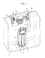
- Fig. 1 shows a portion of a concealed cistern 1.
- the cistern 1 has a drain valve 2, which is mounted on a bottom opening of the Spülkasten emotionss.
- the raisable and lowerable valve body 3 of the drain valve 2 is formed as an overflow pipe, at the lower end of a flange-shaped sealing ring 4 is attached.
- the sealing ring 4 is located in the closed drain valve 2 on a valve seat, which is formed at the top of the Spülkastenêt 6 penetrating pipe socket. If there is a certain amount of water in the cistern 1, the water column pushes the sealing ring 4 against the annular valve seat.
- an annular flange 7 is integrally formed, which rests watertight on a Spülringêt 6 via a sealing ring (not shown).
- the drain valve 2 has a housing 8, which is connected via web-shaped support elements 9 with the flange 7.
- the formed as an overflow valve body 3 is provided with a float (not shown), which is guided in the housing 8.
- the drain valve 2 is provided with a pivotally mounted lever (not shown), which causes a lifting of the valve body 3 during a pivoting movement and is connected to a Bowden cable 10.
- the lever is mounted in a holder 11 which is detachably connected to the housing 8 of the drain valve 2.
- a projection (not shown) is formed, which engages under the lever.
- the lever can pivot upward, so that the lever detects the projection of the valve body 3 and raises it against the pressure on the sealing ring 4 on the sealing ring. In this case, a slight lifting of the sealing ring 4 from the valve seat is sufficient.
- the further lifting of the valve body 3 is effected in cistern 1 filled with water by the float attached to the valve body 3.
- the drive (motor) 12 can also be referred to as a linear motor or a translationally acting actuator. With 13, an electrical connection for the engine 12 is designated.
- the electric motor drive 12 is mounted on a mounting frame 14, which is prepared for mounting on an inspection opening 15 of the cistern 1.
- an electronic control is provided, to which at least one key switch or push button sensor (not shown) is connected for actuating the drain valve 2.
- at least two key switches are connected to the electronic control, wherein a key switch is used to trigger a full flush with a defined amount of water and a second key switch is used to trigger a partial flush with a smaller defined amount of water.
- the in Fig. 1 illustrated cistern 1 also offers the possibility of an independent of the electric motor drive manual operation (triggering) of the drain valve 2.
- the drain valve 2 is additionally provided with a purely mechanical triggering device.
- the mechanical release device on a manual actuator which is connected to a further Bowden cable 16 for actuating the drain valve 2.
- the manual actuator (in Fig. 1 not shown) is formed, for example, as a push button, handle or pull knob and preferably arranged at a hidden location on the outside of the inspection opening 15 covering cover plate or at another location on the outside of the cistern 1-containing wall and accessible to the user if necessary.
- a further lever (not shown) is used, which is also pivotally mounted in the holder 11 and causes a lifting movement of the valve body 3 of the drain valve 2 in a pivoting movement.
- a device according to the invention which makes it possible to operate a lever or other adjusting element on the drain valve 2 for lifting or moving the valve body 3 optionally with an electric motor drive 12 or (independently of the drive 12) with a manual actuator 17.
- a lever or other adjusting element on the drain valve 2 for lifting or moving the valve body 3 optionally with an electric motor drive 12 or (independently of the drive 12) with a manual actuator 17.
- 11 is one with a cistern drain valve 2 according to Fig. 1 detachably connectable holder called. On the holder 11 at least two levers or adjusting elements for lifting the valve body 3 of the drain valve 2 are movably mounted.
- the first lever or the first control element 11.1 is used to trigger a full flush, in which an amount of water in the range of, for example, 6 to 9 liters is passed through a connected to the cistern 1 flushing pipe in a connected toilet bowl, whereas the second control element 11.2 and second lever on the holder 11 of the triggering of a partial flush is used, in which an amount of water, for example, about 3 liters from the cistern 1 is passed into the connected toilet bowl.
- the manual actuators 17, 19 each have a pivotally mounted lever 20. They can also be called force transducers. Because they turn one on the Lever 20 applied compressive force in a force acting on the connected Bowden cable 16 and 21 traction.
- the device according to the invention has a Bowden dipper 22.
- the Bowdenzugweiche 22 includes a movably mounted coupling element 23 to which the Bowden cable 18 connected to the holder 11 is coupled. Further, the Bowdenzugweiche 22 (at least) two drivers 24, 25 which are movable relative to each other and independently, at least a first driver 24 which is coupled to at least a first, the engine 12 associated Bowden cable 26, and at least one second Driver 25, which is coupled to at least a second, the manual actuator 17 associated Bowden cable 21.
- the drivers 24, 25 and the coupling element 23 are slidably mounted in a housing 27.
- the housing 27 has a cup-shaped housing part 27.1 and a housing cover 27.2.
- the cover 27.2 is connected via a hinge 27.3, preferably hinged hinged to the cup-shaped housing part 27.1.
- the cover 27.2 and the housing part 27.1 have mutually associated latching elements.
- the locking elements are formed from resilient latching lugs 28 and their associated recesses 29.
- the recesses 29 are formed on the hinge 27.3 opposite longitudinal side of the housing part 27.1.
- the locking lugs 28 are accordingly formed on the hinge 27.3 opposite longitudinal side of the lid 27.2 on the same.
- the housing 27, namely the cup-shaped housing part 27.1 has elongated, substantially rectilinear ribs 27.4 for guiding the coupling element 23 and / or the drivers 24, 25.
- the ribs 27.4 are formed on the housing bottom inside.
- the ribs 27.4 also substantially rectilinear grooves and / or slots for guiding the coupling element 23 and / or the driver 24, 25 may be formed in the housing 27.
- the coupling element 23 has grooves into which the projections or ribs 27.4 of the housing bottom engage with play.
- the coupling element 23 comprises a plate-shaped element 23.1, which has a slotted receiving eye 23.2 for suspending a nipple firmly connected to the end of the wire core 18.1 of the Bowden cable 18 in the region of its longitudinal central axis. Furthermore, the coupling element 23 is provided with a spring element 30, by means of which it is biased into an initial position.
- the spring element 30 preferably consists of a helical spring. One end of the coil spring 30 is mounted on a arranged on the inside of the housing 27, preferably molded pin 27.5. The other end of the coil spring 30 is inserted into a sleeve-shaped receptacle 23.3, which is connected to the coupling element 23.
- the sleeve-shaped receptacle 23.3 is the slotted receiving eye 23.2 opposite.
- the longitudinal center axis of the pin 27.5 and the coil spring 30 and the longitudinal center axis of the sleeve-shaped receptacle 23.3 are aligned with each other.
- the end portion of the wire core 18.1 of the Bowden cable 18 is aligned with the Longitudinal axis of the pin 27.5 or with the longitudinal center axis of the sleeve-shaped coil spring receptacle 23.3.
- slots 23.6 and / or ribs for guiding the drivers 24, 25 are further formed.
- the respective driver 24, 25 is formed substantially in the form of an elongated cuboid or rod. He has at one of its ends a slotted receiving eyelet 24.1 and 25.1 for hanging a firmly connected to the end of the wire core 21.1 and 26.1 of the Bowden cable 21, 26 nipple. At its other end, the driver 24, 25 has an engaging on an edge of the plate-shaped part 23.1 of the coupling element 23 projection 24.2, 25.2.
- the receiving lug 24.1, 25.1 of the driver 24, 25 is arranged away from the receiving lug 23.2 of the coupling element 23, or in other words, the projection 24.2, 25.2 of the driver 24, 25 engages the edge of the plate-shaped part 23.1 of the coupling piece 23 at which is the receiving eye 23.2.
- FIGS. 2 to 8 recognize that 27 openings 27.6 are formed in the wall of the housing, which serve to introduce ends of the Bowden cables 18, 21, 26 in the housing interior.
- the openings 27.6 are provided in the cup-shaped housing part 27.1 and open at the dividing plane defined by the housing part 27.1 and the housing cover 27.2.
- sleeves 31 are fixed positively, wherein the respective sleeve 31 receives one end of the tubular Bowden cable sheath (Bowden cable sheath).
- the wire core of the Bowden cable 18, 21, 26 terminates in the interior of the housing 27.
- these sleeves 31st have two spaced-apart annular projections 31.1 or have on their lateral surface an annular groove 31.2.
- projections 27.7 are formed with trough-shaped depressions, which are associated with the openings 27.6 in the wall of the cup-shaped housing part 27.2.
- the projections 27.7 engage in the closed position of the cover 27.2 in the annular groove 31.2 of the Bowdenzughülsen 30, so that an additional positive fixing of the sleeves 31 results in the housing 27.
- FIGS. 3 and 4 show the coupling element 23 and the drivers 24, 25 in their initial position (zero position).
- the drivers 24, 25 are in this position next to each other and substantially at the same height.
- the coil spring 30 is not or only slightly compressed in the starting position.
- FIGS. 5 and 6 a position of the Bowden cable switch 22 effected by actuation of the Bowden cable 26 associated with the motor 12 is shown.
- the motor 12 associated driver 24 was used with the Bowden cable 26 closer to the sleeve 31.
- the coil spring 30 is strongly compressed in this position.
- the projecting in the direction of the housing bottom projection 24.2 of the driver 24 abuts the edge of the plate-shaped part 23.1 of the coupling element 23 and has the coupling element 23 taken in the direction of the fixed housing 27 in the sleeve 31 of the Bowden cable 26.
- the other driver 25 which is associated with the Bowden cable 21 and the manual actuator 17 is in its initial position (zero position) according to the FIGS. 3 and 4 remained.
- FIGS. 7 and 8 finally, a position of the Bowdenzugweiche 22 effected by actuation of the manual actuating element 17 associated Bowden cable 21 is shown.
- the manual actuator 17 associated driver 25 was used by means of the Bowden cable 21 closer to the sleeve 31.
- the coil spring 30 is in turn strongly compressed.
- the protruding in the direction of the housing bottom projection 25.2 of the driver 25 abuts the edge of the plate-shaped part 23.1 of the coupling element 23 and has the coupling element 23 taken in the direction of the fixed housing 27 in the sleeve 31 of the Bowden cable 21.
- the driver 12 associated with the driver 24, however, is in its initial position (zero position) according to the FIGS. 3 and 4 remained.
- the Bowdenzugweiche 22 can be variably arranged within a cistern 1 due to the flexibility of the Bowden cables 18, 21, 26.
- the length of the Bowden cables 18, 21, 26 can be adjusted as needed, wherein the housing 27 of the Bowdenzugweiche 22 each by the coupled with the coupling piece 23 (third) Bowden cable 18 can be arranged at a distance from the drain valve 2.
- the attached at the ends of the Bowden cable cores nipples are fixed to the respective wire core or detachably connected as a clamping nipple.
- the motor 12 is provided with a flexible power supply or control cable 13.
- the embodiment of the present invention is not limited to the embodiment described above and shown in the drawing. Rather, numerous variants are possible, even with deviating design of the invention specified in the accompanying claims Make use.
- the device according to the invention can not be used only in a sanitary cistern 1.
- a use in other sanitary drain valves, such as a bathtub drain valve is possible.
- the Bowden cables 16 and 18 without a releasable support 11 according to Fig. 2 be mounted directly on the housing of a drain valve 2.
- the use of a detachable holder 11 according to Fig. 2 However, in particular with regard to a pre-assembly of the Bowden cables 16, 18, the manual actuators 17, 19 and the electric motor drive 12 advantageous and therefore preferred.
Landscapes
- Engineering & Computer Science (AREA)
- General Engineering & Computer Science (AREA)
- Mechanical Engineering (AREA)
- Water Supply & Treatment (AREA)
- Health & Medical Sciences (AREA)
- Life Sciences & Earth Sciences (AREA)
- Hydrology & Water Resources (AREA)
- Public Health (AREA)
- Aviation & Aerospace Engineering (AREA)
- Environmental & Geological Engineering (AREA)
- Mechanically-Actuated Valves (AREA)
- Sink And Installation For Waste Water (AREA)
- Electrically Driven Valve-Operating Means (AREA)
Abstract
Description
Die Erfindung betrifft eine Vorrichtung zur Betätigung eines sanitären Ablaufventils, insbesondere Spülkasten-Ablaufventils oder Badewannen-Ablaufventils, mit mindestens einem elektromotorischen Antrieb und einer mindestens ein erstes manuelles Betätigungselement aufweisenden manuellen Auslöseeinrichtung, wobei der elektromotorische Antrieb über mindestens einen ersten Bowdenzug das Ablaufventil betätigt und das mindestens eine erste manuelle Betätigungselement mit mindestens einem zweiten Bowdenzug zur Betätigung des Ablaufventils versehen ist.The invention relates to a device for actuating a sanitary drain valve, in particular Spülkasten-drain valve or bathtub drain valve, with at least one electric motor drive and at least a first manual actuator having manual release device, wherein the electric motor drive via at least one first Bowden cable actuates the drain valve and the at least one first manual actuating element is provided with at least one second Bowden cable for actuating the drain valve.
Eine derartige Vorrichtung ist beispielsweise aus der
Herkömmliche Betätigungsplatten zur Auslösung einer WC- oder Urinalspülung funktionieren rein mechanisch. Sie weisen üblicherweise eine oder zwei Betätigungstasten auf, die beweglich, meist schwenkbar in der Betätigungsplatte gelagert sind. Des Weiteren sind auch Vorrichtungen zur Auslösung einer WC- oder Urinalspülung bekannt, die einen elektromagnetischen oder elektromotorischen Antrieb aufweisen.Conventional actuating plates for triggering a toilet or urinal flushing work purely mechanically. They usually have one or two operation keys that are movable, usually pivotally mounted in the actuator plate. Furthermore, devices for triggering a toilet or urinal flush are known, which have an electromagnetic or electric motor drive.
Die
Sanitäre Spülkästen sind heutzutage üblicherweise in Zweimengentechnik ausgeführt, d.h. sie ermöglichen die Auslösung einer Vollspülung mit einer relativ großen Spülwassermenge sowie alternativ - für Fälle, in denen eine geringere Spülwassermenge ausreicht - die Auslösung einer Teilspülung mit einer relativ kleinen Spülwassermenge.Sanitary cisterns are nowadays usually designed in dual-mode, i. They allow the initiation of a full flush with a relatively large amount of flushing water and alternatively - for cases in which a lower amount of flushing sufficient - the release of a partial flush with a relatively small amount of flushing water.
Bei einer gemäß der
Der vorliegenden Erfindung lag daher die Aufgabe zugrunde, eine Vorrichtung der eingangs genannten Art dahingehend weiterzuentwickeln, dass deren Ablaufventil sowohl motorisch als auch bei Bedarf manuell, rein mechanisch mit kleiner und großer Spülwassermenge betrieben werden kann.The present invention therefore an object of the invention to further develop a device of the type mentioned in that the drain valve can be operated both manually and on demand manually, purely mechanically with small and large amount of flushing water.
Diese Aufgabe wird erfindungsgemäß durch eine Vorrichtung mit den Merkmalen des Anspruchs 1 gelöst.This object is achieved by a device having the features of
Die erfindungsgemäße Vorrichtung ist dadurch gekennzeichnet, dass der mindestens eine erste Bowdenzug, der dem elektromotorischen Antrieb zugeordnet ist, mit mindestens einem ersten Mitnehmer gekoppelt ist, und der mindestens eine zweite Bowdenzug, der dem mindestens einen ersten manuellen Betätigungselement zugeordnet ist, mit mindestens einem zweiten Mitnehmer gekoppelt ist, wobei die Mitnehmer relativ zueinander bewegbar sind, und wobei der jeweilige Mitnehmer bei einer auf ihn über den mit ihm gekoppelten Bowdenzug übertragenden Bewegung ein Kupplungselement mitnimmt, an dem mindestens ein dritter Bowdenzug angekoppelt ist, der zur Betätigung des Ablaufventils mit demselben gekoppelt ist.The device according to the invention is characterized in that the at least one first Bowden cable, which is assigned to the electromotive drive, is coupled to at least one first driver, and the at least one second Bowden cable, which is assigned to the at least one first manual actuating element, with at least one second Driver is coupled, wherein the drivers are movable relative to each other, and wherein the respective driver in a transmitted to him via the Bowden cable coupled with it movement carries a coupling element to which at least a third Bowden cable is coupled, coupled to actuate the drain valve with the same is.
Die erfindungsgemäße Vorrichtung weist somit eine Multibetätigungskomponente für Bowdenzüge auf, die es ermöglicht, mit einem geeigneten Zweimengen-Ablaufventil eine Vollspülung und wahlweise eine Teilspülung jeweils mit rein mechanisch funktionierenden Betätigungssystemen und eine Voll- oder Teilspülung mit einem elektromotorischen Antrieb auszulösen. Die Multibetätigungskomponente der erfindungsgemäßen Vorrichtung kann auch als Bowdenzugweiche bezeichnet werden.The device according to the invention thus has a Multituätigungskomponente for Bowden cables, which makes it possible to trigger a full flush and optionally a partial flush each with purely mechanically functioning actuation systems and a full or partial flush with an electric motor drive with a suitable dual rate drain valve. The multi-component of the device according to the invention can also be referred to as Bowdenzugweiche.
Die Bowdenzugweiche ermöglicht die Verwirklichung von mehr als zwei Betätigungsvarianten. Mehrere unabhängig voneinander betätigbare Bowdenzüge sind dabei mit einem gemeinsamen Bowdenzug zur Auslösung eines Ablaufventils bzw. zur Betätigung eines Auslösehebels des Ablaufventils gekoppelt. Mit der erfindungsgemäßen Vorrichtung können folglich mehrere Betätigungsvarianten miteinander kombiniert werden.The Bowden Dodge allows the implementation of more than two actuation variants. Several independently operable Bowden cables are coupled to a common Bowden cable for triggering a drain valve or for actuating a trigger lever of the drain valve. Consequently, a plurality of actuation variants can be combined with one another using the device according to the invention.
In einer bevorzugten Ausgestaltung weist die manuelle Auslöseeinrichtung der erfindungsgemäßen Vorrichtung mindestens ein zweites manuelles Betätigungselement auf, das mit mindestens einem vierten Bowdenzug versehen ist, der zur Betätigung des Ablaufventils mit demselben gekoppelt ist. Bei Anwendung der erfindungsgemäßen Vorrichtung in Verbindung mit einem Zweimengen-Ablaufventil eines Toilettenspülkastens können das zweite manuelle Betätigungselement und der mindestens eine vierte Bowdenzug der Auslösung einer Teilspülung dienen, wohingegen das erste manuelle Betätigungselement und der diesem zugeordnete mindestens eine Bowdenzug der Auslösung einer Vollspülung zugeordnet sind.In a preferred embodiment, the manual release device of the device according to the invention on at least a second manual actuator, which is provided with at least a fourth Bowden cable, which is coupled to actuate the drain valve with the same. When using the device according to the invention in conjunction with a dual-volume drain valve of a toilet cistern, the second manual actuator and the at least one fourth Bowden cable serve to trigger a partial flush, whereas the first manual actuator and associated therewith at least one Bowden cable are associated with triggering a full flush.
Eine weitere bevorzugte Ausgestaltung der erfindungsgemäßen Vorrichtung ist dadurch gekennzeichnet, dass die Mitnehmer und das Kupplungselement in einem Gehäuse bewegbar, vorzugsweise verschiebbar gelagert sind, wobei das Gehäuse einen schalenförmigen Gehäuseteil und einen abnehmbaren oder aufklappbaren Deckel aufweist. Das Gehäuse bietet neben einer einfachen Montierbarkeit und zuverlässigen beweglichen Lagerung der Mitnehmer und des Kupplungselementes auch einen sicheren Schutz dieser Komponenten vor äußeren mechanischen Einwirkungen.A further preferred embodiment of the device according to the invention is characterized in that the driver and the coupling element are mounted in a housing movable, preferably displaceable, wherein the housing has a cup-shaped housing part and a removable or hinged lid. The housing offers next to a simple mountability and reliable movable mounting of the driver and the coupling element and a safe protection of these components from external mechanical effects.
Nach einer weiteren bevorzugten Ausgestaltung der erfindungsgemäßen Vorrichtung weisen der Deckel und das schalenförmige Gehäuseteil einander zugeordnete Rastelemente auf. Die Rastelemente ermöglichen ein besonders einfaches und schnelles Verbinden der genannten Gehäuseteile und somit ein einfaches und schnelles Schließen des Gehäuses.According to a further preferred embodiment of the device according to the invention, the lid and the shell-shaped housing part have mutually associated latching elements. The locking elements allow a particularly simple and quick connection of said housing parts and thus a simple and fast closing of the housing.
Eine weitere vorteilhafte Ausgestaltung der erfindungsgemäßen Vorrichtung sieht vor, dass das Gehäuse Nuten, Schlitze und/oder Rippen zur Führung des Kupplungselements und/oder der Mitnehmer aufweist. Die genannten Führungsmittel sind dabei in dem Gehäuse integriert. Die Herstellung und Montage weiterer separater Führungselemente ist somit nicht erforderlich, so dass unnötige Material- und Fertigungskosten vermieden werden können.A further advantageous embodiment of the device according to the invention provides that the housing has grooves, slots and / or ribs for guiding the coupling element and / or the driver. The said guide means are integrated in the housing. The production and assembly of further separate guide elements is thus not required, so that unnecessary material and manufacturing costs can be avoided.
Eine weitere vorteilhafte Ausgestaltung der erfindungsgemäßen Vorrichtung sieht vor, dass in der Wandung des Gehäuses Öffnungen oder Ausnehmungen ausgebildet sind, an denen Hülsen zur Aufnahme eines Endes des schlauchförmigen Mantels des ersten, zweiten und dritten Bowdenzuges formschlüssig festgelegt sind. Diese Ausgestaltung ermöglicht eine einfache und zuverlässige Verbindung der genannten Bowdenzüge mit dem Gehäuse.A further advantageous embodiment of the device according to the invention provides that in the wall of the housing openings or recesses are formed, on which sleeves are fixed positively for receiving one end of the tubular jacket of the first, second and third Bowden cable. This embodiment enables a simple and reliable connection of said Bowden cables to the housing.
In funktioneller Hinsicht ist es vorteilhaft, wenn gemäß einer weiteren bevorzugten Ausgestaltung der erfindungsgemäßen Vorrichtung das Kupplungselement und/oder die Mitnehmer mit mindestens einem Federelement in eine Ausgangsposition vorgespannt sind. Diese Ausgestaltung vereinfacht die manuelle Betätigung des sanitären Ablaufventils. Ein für die manuelle Betätigung des Ablaufventils vorgesehenes Bedienelement, beispielsweise eine Drucktaste, wird nach der manuellen Betätigung des Ablaufventils in eine Ausgangsposition zurückbewegt, wobei das das Kupplungselement und/oder die Mitnehmer beaufschlagende Federelement die Bewegung des Bedienelements in seine Ausgangsposition unterstützt.In functional terms, it is advantageous if according to a further preferred embodiment of the device according to the invention, the coupling element and / or the driver are biased with at least one spring element in an initial position. This embodiment simplifies the manual operation of the sanitary drain valve. A provided for manual operation of the drain valve control element, such as a push button is moved back to the manual operation of the drain valve in an initial position, wherein the coupling element and / or the driver acting spring element Supported movement of the control element to its starting position.
Nach einer weiteren bevorzugten Ausgestaltung der erfindungsgemäßen Vorrichtung ist das Kupplungselement mit einem plattenförmigen Element versehen, das Nuten, Schlitze und/oder Rippen zur Führung der Mitnehmer aufweist. Der jeweilige Mitnehmer weist dabei vorzugsweise einen an einer Kante des plattenförmigen Elements des Kupplungselements angreifenden Vorsprung auf. Diese Ausgestaltung ermöglicht eine kompakte Bauweise der Bowdenzugweiche bei sehr zuverlässiger Funktion. Die Herstellung und Montage separater Führungselemente ist insoweit wiederum nicht erforderlich, was sich günstig auf die Material- und Fertigungskosten, insbesondere die Montagekosten auswirkt.According to a further preferred embodiment of the device according to the invention, the coupling element is provided with a plate-shaped element which has grooves, slots and / or ribs for guiding the driver. The respective driver preferably has a projection engaging an edge of the plate-shaped element of the coupling element. This embodiment allows a compact design of the Bowdenzugweiche with very reliable function. The production and installation of separate guide elements is again not required, which has a favorable effect on the material and manufacturing costs, in particular the installation costs.
Weitere bevorzugte und vorteilhafte Ausgestaltungen der erfindungsgemäßen Vorrichtung sind in den Unteransprüchen angegeben.Further preferred and advantageous embodiments of the device according to the invention are specified in the subclaims.
Nachfolgend wird die Erfindung anhand einer ein Ausführungsbeispiel darstellenden Zeichnung näher erläutert. Es zeigen:
- Fig. 1
- einen Abschnitt eines aus der
DE 20 2007 003 163 U1 - Fig. 2
- ein erfindungsgemäßes System umfassend einen elektromotorischen Antrieb, manuelle Betätigungselemente in Form von Kraftwandlern, Bowdenzüge, eine Bowdenzugweiche sowie eine mit einem Spülkasten-Ablaufventil lösbar verbindbare Halterung, in perspektivischer Darstellung;
Figuren 3 und 4- die Bowdenzugweiche der
Fig. 2 in ihrer Nullstellung (Ausgangsstellung) mit Abschnitten der daran montierten Bowdenzüge, in perspektivischer Ansicht bzw. Draufsicht; - Figuren 5
- und 6 die Bowdenzugweiche gemäß den
Figuren 3 und 4 - Figuren 7
- und 8 die Bowdenzugweiche gemäß den
Figuren 3 und 4
- Fig. 1
- a section of one from the
DE 20 2007 003 163 U1 - Fig. 2
- a system according to the invention comprising an electric motor drive, manual actuators in the form of force transducers, Bowden cables, a Bowden switch and one with a Cistern drain valve releasably connectable holder, in perspective view;
- FIGS. 3 and 4
- the Bowdenzugweiche the
Fig. 2 in its zero position (initial position) with sections of the Bowden cables mounted thereon, in perspective view and top view, respectively; - Figures 5
- and 6 the Bowden Dodge according to
FIGS. 3 and 4 in an actuated position caused by the electromotive drive, in perspective view and plan view, respectively; and - FIGS. 7
- and 8 the Bowden Dodge according to
FIGS. 3 and 4 in a caused by a manual actuator operating position, in perspective view and plan view.
Das Ablaufventil 2 weist ein Gehäuse 8 auf, das über stegförmige Stützelemente 9 mit dem Flansch 7 verbunden ist. Der als Überlaufrohr ausgebildete Ventilkörper 3 ist mit einem Schwimmer (nicht gezeigt) versehen, der in dem Gehäuse 8 geführt ist.The
Das Ablaufventil 2 ist mit einem schwenkbar gelagerten Hebel (nicht gezeigt) versehen, der bei einer Schwenkbewegung ein Anheben des Ventilkörpers 3 bewirkt und mit einem Bowdenzug 10 verbunden ist. Der Hebel ist in einer Halterung 11 gelagert, die mit dem Gehäuse 8 des Ablaufventils 2 lösbar verbunden ist. An der Außenseite des rohrförmigen Ventilkörpers 3 ist ein Vorsprung (nicht gezeigt) ausgebildet, den der Hebel untergreift. Mittels des Bowdenzuges 10 lässt sich der Hebel nach oben schwenken, so dass der Hebel den Vorsprung des Ventilkörpers 3 erfasst und diesen gegen den auf den Dichtungsring 4 lastenden Druck der Wassersäule anhebt. Dabei genügt ein geringes Anheben des Dichtungsringes 4 vom Ventilsitz. Das weitere Anheben des Ventilkörpers 3 wird bei mit Wasser gefülltem Spülkasten 1 durch den am Ventilkörper 3 befestigten Schwimmer bewirkt.The
Die Betätigung des Hebels erfolgt über den Bowdenzug mittels eines elektromotorischen Antriebes 12, vorzugsweise eines elektrischen Linearantriebes. Der Antrieb (Motor) 12 kann auch als Linearmotor oder translatorisch wirkender Aktor bezeichnet werden. Mit 13 ist ein Elektroanschluss für den Motor 12 bezeichnet. Der elektromotorischen Antrieb 12 ist an einem Einbaurahmen 14 montiert, der für eine Montage an einer Revisionsöffnung 15 des Spülkastens 1 hergerichtet ist.The actuation of the lever via the Bowden cable by means of an
Zur Ansteuerung des elektromotorischen Antriebes 12 ist eine elektronische Steuerung vorgesehen, an der mindestens ein Tastschalter oder Tastsensor (nicht gezeigt) zur Betätigung des Ablaufventils 2 angeschlossen ist. Vorzugsweise sind an der elektronischen Steuerung jedoch mindestens zwei Tastschalter angeschlossen, wobei ein Tastschalter der Auslösung einer Vollspülung mit einer definierten Wassermenge dient und ein zweiter Tastschalter der Auslösung einer Teilspülung mit einer geringeren definierten Wassermenge dient.For controlling the
Der in
Für die manuelle Betätigung (Auslösung) des Ablaufventils 2 wird ein weiterer Hebel (nicht gezeigt) genutzt, der ebenfalls in der Halterung 11 schwenkbar gelagert ist und bei einer Schwenkbewegung ein Anheben des Ventilkörpers 3 des Ablaufventils 2 bewirkt.For the manual actuation (triggering) of the
In
An der Halterung 11 sind Bowdenzüge 16, 18, zur Betätigung der dem Ablaufventil 2 zugeordneten Hebel bzw. Stellelemente 11.1, 11.2 montiert. Einer der Hebel bzw. eines (11.1) der Stellelemente 11.1, 11.2 kann wahlweise mittels des Motors 12 oder mittels eines manuellen Betätigungselements 17 über den Bowdenzug 18 betätigt werden. Der andere Hebel bzw. das andere Stellelement 11.2 ist über den Bowdenzug 16 mit einem zweiten manuellen Betätigungselement 19 gekoppelt.On the
Die manuellen Betätigungselemente 17, 19 weisen jeweils einen schwenkbar gelagerten Hebel 20 auf. Sie können auch als Kraftwandler bezeichnet werden. Denn sie wandeln eine auf den Hebel 20 ausgeübte Druckkraft in eine auf den angeschlossenen Bowdenzug 16 bzw. 21 wirkende Zugkraft um.The
Um einen der Hebel bzw. eines (11.1) der Stellelemente 11.1, 11.2 wahlweise elektromotorisch oder manuell betätigen zu können, weist die erfindungsgemäße Vorrichtung eine Bowdenzugweiche 22 auf. Die Bowdenzugweiche 22 umfasst ein beweglich gelagertes Kupplungselement 23, an dem der mit der Halterung 11 verbundene Bowdenzug 18 angekoppelt ist. Ferner umfasst die Bowdenzugweiche 22 (mindestens) zwei Mitnehmer 24, 25, die relativ zueinander sowie unabhängig voneinander bewegbar sind, und zwar mindestens einen ersten Mitnehmer 24, der mit mindestens einem ersten, dem Motor 12 zugeordneten Bowdenzug 26 gekoppelt ist, und mindestens einen zweiten Mitnehmer 25, der mit mindestens einem zweiten, dem manuellen Betätigungselement 17 zugeordneten Bowdenzug 21 gekoppelt ist.In order to be able to actuate one of the levers or one (11.1) of the adjusting elements 11.1, 11.2 selectively by electric motor or manually, the device according to the invention has a
Die Mitnehmer 24, 25 und das Kupplungselement 23 sind in einem Gehäuse 27 verschiebbar gelagert. Das Gehäuse 27 weist einen schalenförmigen Gehäuseteil 27.1 und einen Gehäusedeckel 27.2 auf. Der Deckel 27.2 ist über ein Scharnier 27.3, vorzugsweise Filmscharnier aufklappbar mit dem schalenförmigen Gehäuseteil 27.1 verbunden. Der Deckel 27.2 und das Gehäuseteil 27.1 weisen einander zugeordnete Rastelemente auf. Die Rastelemente sind aus federelastischen Rastnasen 28 und diesen zugeordneten Ausnehmungen 29 gebildet. Die Ausnehmungen 29 sind an der dem Scharnier 27.3 gegenüberliegenden Längsseite des Gehäuseteils 27.1 ausgebildet. Die Rastnasen 28 sind dementsprechend an der dem Scharnier 27.3 gegenüberliegenden Längsseite des Deckels 27.2 an demselben angeformt.The
Das Gehäuse 27, und zwar das schalenförmige Gehäuseteil 27.1 weist längliche, im Wesentlichen geradlinige Rippen 27.4 zur Führung des Kupplungselements 23 und/oder der Mitnehmer 24, 25 auf. In dem dargestellten Ausführungsbeispiel sind die Rippen 27.4 an der Gehäusebodeninnenseite ausgebildet. Anstelle der Rippen 27.4 können auch im Wesentlichen geradlinige Nuten und/oder Schlitze zur Führung des Kupplungselements 23 und/oder der Mitnehmer 24, 25 in dem Gehäuse 27 ausgebildet sein. Das Kupplungselement 23 weist Nuten auf, in welche die Vorsprünge bzw. Rippen 27.4 des Gehäusebodens mit Spiel eingreifen.The
Das Kupplungselement 23 umfasst ein plattenförmiges Element 23.1, das im Bereich seiner Längmittelachse eine geschlitzte Aufnahmeöse 23.2 zum Einhängen eines mit dem Ende der Drahtseele 18.1 des Bowdenzuges 18 fest verbundenen Nippels aufweist oder trägt. Des Weiteren ist das Kupplungselement 23 mit einem Federelement 30 versehen, mittels dem es in eine Ausgangsposition vorgespannt ist. Das Federelement 30 besteht vorzugsweise aus einer Schraubenfeder. Ein Ende der Schraubenfeder 30 ist auf einen an der Innenseite des Gehäuses 27 angeordneten, vorzugsweise angeformten Stift 27.5 aufgesteckt. Das andere Ende der Schraubenfeder 30 ist in eine hülsenförmige Aufnahme 23.3 eingesteckt, die mit dem Kupplungselement 23 verbunden ist. Die hülsenförmige Aufnahme 23.3 liegt der geschlitzten Aufnahmeöse 23.2 gegenüber. Die Längsmittelachse des Stiftes 27.5 bzw. der Schraubenfeder 30 sowie die Längsmittelachse der hülsenförmigen Aufnahme 23.3 fluchten miteinander. Vorzugsweise fluchtet auch der Endabschnitt der Drahtseele 18.1 des Bowdenzuges 18 mit der Längsmittelachse des Stiftes 27.5 bzw. mit der Längsmittelachse der hülsenförmigen Schraubenfederaufnahme 23.3.The
In bzw. an dem plattenförmigen Teil 23.1 des Kupplungsstückes 23 sind ferner Nuten, Schlitze 23.6 und/oder Rippen zur Führung der Mitnehmer 24, 25 ausgebildet. Der jeweilige Mitnehmer 24, 25 ist im Wesentlichen in Form eines länglichen Quaders oder Stabes ausgebildet. Er weist an einem seiner Enden eine geschlitzte Aufnahmeöse 24.1 bzw. 25.1 zum Einhängen eines mit dem Ende der Drahtseele 21.1 bzw. 26.1 des Bowdenzuges 21, 26 fest verbundenen Nippels auf. An seinem anderen Ende hat der Mitnehmer 24, 25 einen an einer Kante des plattenförmigen Teils 23.1 des Kupplungselements 23 angreifenden Vorsprung 24.2, 25.2. Die Aufnahmeöse 24.1, 25.1 des Mitnehmers 24, 25 ist dabei abgewandt von der Aufnahmeöse 23.2 des Kupplungselements 23 angeordnet, oder anders ausgedrückt, der Vorsprung 24.2, 25.2 des Mitnehmers 24, 25 greift an der Kante des plattenförmigen Teils 23.1 des Kupplungsstückes 23 an, an welcher sich dessen Aufnahmeöse 23.2 befindet.In or on the plate-shaped part 23.1 of the
Des Weiteren ist in den
Die
In den
In den
Die Bowdenzugweiche 22 lässt sich aufgrund der Flexibilität der Bowdenzüge 18, 21, 26 variabel innerhalb eines Spülkastens 1 anordnen. Die Länge der Bowdenzüge 18, 21, 26 lässt sich hierzu bedarfsgerecht anpassen, wobei das Gehäuse 27 der Bowdenzugweiche 22 jeweils durch den mit dem Kupplungsstück 23 gekoppelten (dritten) Bowdenzug 18 mit Abstand zu dem Ablaufventil 2 angeordnet werden kann. Die an den Enden der Bowdenzug-Drahtseelen angebrachten Nippel sind mit der jeweiligen Drahtseele fest oder als Klemmnippel lösbar verbunden. Der Motor 12 ist mit einem flexiblen Stromnetz- bzw. Steuerungskabel 13 versehen.The
Die Ausführung der vorliegenden Erfindung ist nicht auf das vorstehend beschriebene und in der Zeichnung dargestellte Ausführungsbeispiel beschränkt. Vielmehr sind zahlreiche Varianten möglich, die auch bei abweichender Gestaltung von der in den beiliegenden Ansprüchen angegebenen Erfindung Gebrauch machen. Insbesondere kann die erfindungsgemäße Vorrichtung nicht nur bei einem sanitären Spülkasten 1 zum Einsatz kommen. Ebenso ist auch eine Verwendung bei anderen sanitären Ablaufventilen, beispielsweise einem Badewannen-Ablaufventil möglich. Insbesondere können die Bowdenzüge 16 und 18 auch ohne eine lösbare Halterung 11 gemäß
Claims (10)
dadurch gekennzeichnet, dass die manuelle Auslöseeinrichtung mindestens ein zweites manuelles Betätigungselement (19) aufweist, das mit mindestens einem vierten Bowdenzug (16) versehen ist, der zur Betätigung des Ablaufventils (2) mit demselben gekoppelt ist.Device according to claim 1,
characterized in that the manual triggering device comprises at least a second manual actuating element (19) which is provided with at least a fourth Bowden cable (16) which is coupled to the actuation of the drain valve (2) with the same.
dadurch gekennzeichnet, dass die Mitnehmer (24, 25) und das Kupplungselement (23) in einem Gehäuse (27) bewegbar, vorzugsweise verschiebbar gelagert sind, wobei das Gehäuse (27) einen schalenförmigen Gehäuseteil (27.1) und einen abnehmbaren oder aufklappbaren Deckel (27.2) aufweist.Apparatus according to claim 1 or 2,
characterized in that the drivers (24, 25) and the coupling element (23) in a housing (27) movable, preferably slidably mounted, wherein the housing (27) has a cup-shaped housing part (27.1) and a removable or hinged lid (27.2 ) having.
dadurch gekennzeichnet, dass der Deckel (27.2) und das schalenförmige Gehäuseteil (27.1) mit einander zugeordneten Rastelementen (28, 29) versehen sind.Device according to claim 3,
characterized in that the lid (27.2) and the cup-shaped housing part (27.1) with mutually associated latching elements (28, 29) are provided.
dadurch gekennzeichnet, dass das Gehäuse (27) Nuten, Schlitze und/oder Rippen (27.4) zur Führung des Kupplungselements (23) und/oder der Mitnehmer (24, 25) aufweist.Apparatus according to claim 3 or 4,
characterized in that the housing (27) grooves, slots and / or ribs (27.4) for guiding the coupling element (23) and / or the driver (24, 25).
dadurch gekennzeichnet, dass in der Wandung des Gehäuses (27) Ausnehmungen oder Öffnungen (27.6) ausgebildet sind, an denen Hülsen (31) zur Aufnahme eines Endes des schlauchförmigen Mantels des ersten, zweiten und dritten Bowdenzuges (18, 21, 26) formschlüssig festgelegt sind.Device according to one of claims 3 to 5,
characterized in that in the wall of the housing (27) recesses or openings (27.6) are formed, on which sleeves (31) for receiving one end of the tubular jacket of the first, second and third Bowden cables (18, 21, 26) fixed positively are.
dadurch gekennzeichnet, dass das Kupplungselement (23) und/oder die Mitnehmer (24, 25) mit mindestens einem Federelement (30) in eine Ausgangsposition vorgespannt sind.Device according to one of claims 1 to 6,
characterized in that the coupling element (23) and / or the drivers (24, 25) are biased with at least one spring element (30) in an initial position.
dadurch gekennzeichnet, dass das Kupplungselement (23) mit einem plattenförmigen Element (23.1) versehen ist, das Nuten, Schlitze (23.6) und/oder Rippen zur Führung der Mitnehmer (24, 25) aufweist.Device according to one of claims 1 to 7,
characterized in that the coupling element (23) with a plate-shaped element (23.1) is provided, the grooves, slots (23.6) and / or ribs for guiding the drivers (24, 25).
dadurch gekennzeichnet, dass der jeweilige Mitnehmer (24, 25) einen an einer Kante des plattenförmigen Elements (23.1) des Kupplungselements (23) angreifenden Vorsprung (24.2, 25.2) aufweist.Device according to claim 8,
characterized in that the respective driver (24, 25) on one edge of the plate-shaped element (23.1) of the coupling element (23) engaging projection (24.2, 25.2).
dadurch gekennzeichnet, dass der jeweilige Mitnehmer (24, 25) im Wesentlichen in Form eines Stabes oder länglichen Quaders ausgebildet ist.Device according to one of claims 1 to 9,
characterized in that the respective driver (24, 25) is formed substantially in the form of a rod or elongated cuboid.
Priority Applications (1)
| Application Number | Priority Date | Filing Date | Title |
|---|---|---|---|
| PL12167616T PL2543782T3 (en) | 2011-07-07 | 2012-05-11 | Device for actuating a sanitary drainage valve, in particular flushing valve or bath tub drainage valve |
Applications Claiming Priority (1)
| Application Number | Priority Date | Filing Date | Title |
|---|---|---|---|
| DE202011103214U DE202011103214U1 (en) | 2011-07-07 | 2011-07-07 | Device for actuating a sanitary drain valve, in particular Spülkasten- or bathtub drain valve |
Publications (3)
| Publication Number | Publication Date |
|---|---|
| EP2543782A2 true EP2543782A2 (en) | 2013-01-09 |
| EP2543782A3 EP2543782A3 (en) | 2014-12-24 |
| EP2543782B1 EP2543782B1 (en) | 2016-01-06 |
Family
ID=46317133
Family Applications (1)
| Application Number | Title | Priority Date | Filing Date |
|---|---|---|---|
| EP12167616.7A Active EP2543782B1 (en) | 2011-07-07 | 2012-05-11 | Device for actuating a sanitary drainage valve, in particular flushing valve or bath tub drainage valve |
Country Status (4)
| Country | Link |
|---|---|
| EP (1) | EP2543782B1 (en) |
| DE (1) | DE202011103214U1 (en) |
| ES (1) | ES2565495T3 (en) |
| PL (1) | PL2543782T3 (en) |
Cited By (2)
| Publication number | Priority date | Publication date | Assignee | Title |
|---|---|---|---|---|
| US10907332B2 (en) | 2017-09-01 | 2021-02-02 | Kohler Co. | Flush actuator assembly |
| IT202100003224A1 (en) * | 2021-02-12 | 2022-08-12 | Oli Sist Sanitarios S A | PLATE ASSEMBLY FOR ONE FLUSH CISTERN |
Families Citing this family (2)
| Publication number | Priority date | Publication date | Assignee | Title |
|---|---|---|---|---|
| DE202014104522U1 (en) * | 2014-09-22 | 2016-01-04 | Viega Gmbh & Co. Kg | Drain fitting for a sink, in particular kitchen sink |
| CN107143014B (en) * | 2017-06-07 | 2023-02-10 | 厦门瑞尔特卫浴科技股份有限公司 | Double-row toggle structure |
Citations (1)
| Publication number | Priority date | Publication date | Assignee | Title |
|---|---|---|---|---|
| DE202007003163U1 (en) | 2007-03-01 | 2008-07-17 | Viega Gmbh & Co. Kg | Device for the electrical triggering of a rinsing process in a sanitary cistern |
Family Cites Families (3)
| Publication number | Priority date | Publication date | Assignee | Title |
|---|---|---|---|---|
| DE19816991C2 (en) * | 1998-04-17 | 2000-11-02 | Daimler Chrysler Ag | Actuation system for vehicles |
| DE102005037122A1 (en) * | 2005-08-06 | 2007-02-08 | Abertax Research And Development Ltd. | Water tank for toilet or roof cistern, has float-assisted valve plug at base, raised by manual operation or by solenoid under control, permitting regular automatic operation |
| DE102007052771B4 (en) * | 2007-11-02 | 2020-01-02 | Magna BÖCO GmbH | Device for connecting at least two cables to one another |
-
2011
- 2011-07-07 DE DE202011103214U patent/DE202011103214U1/en not_active Expired - Lifetime
-
2012
- 2012-05-11 PL PL12167616T patent/PL2543782T3/en unknown
- 2012-05-11 EP EP12167616.7A patent/EP2543782B1/en active Active
- 2012-05-11 ES ES12167616.7T patent/ES2565495T3/en active Active
Patent Citations (1)
| Publication number | Priority date | Publication date | Assignee | Title |
|---|---|---|---|---|
| DE202007003163U1 (en) | 2007-03-01 | 2008-07-17 | Viega Gmbh & Co. Kg | Device for the electrical triggering of a rinsing process in a sanitary cistern |
Cited By (3)
| Publication number | Priority date | Publication date | Assignee | Title |
|---|---|---|---|---|
| US10907332B2 (en) | 2017-09-01 | 2021-02-02 | Kohler Co. | Flush actuator assembly |
| IT202100003224A1 (en) * | 2021-02-12 | 2022-08-12 | Oli Sist Sanitarios S A | PLATE ASSEMBLY FOR ONE FLUSH CISTERN |
| EP4043653A1 (en) * | 2021-02-12 | 2022-08-17 | Oli - Sistemas Sanitarios, S.A. | Control plate assembly for a flushing tank |
Also Published As
| Publication number | Publication date |
|---|---|
| EP2543782A3 (en) | 2014-12-24 |
| EP2543782B1 (en) | 2016-01-06 |
| ES2565495T3 (en) | 2016-04-05 |
| DE202011103214U1 (en) | 2012-10-12 |
| PL2543782T3 (en) | 2016-06-30 |
Similar Documents
| Publication | Publication Date | Title |
|---|---|---|
| EP2543782B1 (en) | Device for actuating a sanitary drainage valve, in particular flushing valve or bath tub drainage valve | |
| DE102018123949A1 (en) | actuator | |
| EP1964988B1 (en) | Electro-mechanical flush mechanism | |
| EP1895067B1 (en) | Device for actuating a WC tank mounted flush with the wall with dual amount flushing system | |
| DE3132270A1 (en) | MOTORIZED ANTENNA SYSTEM | |
| EP1916344A2 (en) | Actuation device for the drain valve of a bathroom cistern | |
| EP1794377A1 (en) | Concealed sanitary fitting | |
| DE102016006751A1 (en) | Actuation unit for a manual transmission of a switchable drive train | |
| DE10309644A1 (en) | Device for motorized actuation and emergency device for manual actuation of a lock for flaps or doors of vehicles, in particular a glove box lock | |
| EP1916343B1 (en) | Dual flush valve | |
| DE102016121199A1 (en) | Locking device for a motor vehicle | |
| EP1316131A1 (en) | Locking device for withdrawable circuit-breakers | |
| EP2388379B1 (en) | Actuation device for a cistern | |
| DE102014225756A1 (en) | Device for the electrical triggering of a rinsing process in a sanitary cistern | |
| EP2775048A1 (en) | Kit comprising a basic drainage body and a plurality of different actuation modules | |
| DE10359246B4 (en) | Hand brake lever device of a vehicle | |
| EP1842972A1 (en) | Sanitary valve with concealed spout | |
| CH682837A5 (en) | Bowden cable system for remote control of toilet flush unit - incorporates push-pull knob on casing and cable and end fittings are made of one piece of plastics | |
| WO2003038965A2 (en) | Mounting structure for an electric switch | |
| DE102005011984A1 (en) | Electrically operated stand fitting for use with e.g. bathtub, has body connected with water outlet at mixer and shut-off valve units, arranged below seat and formed separately from one another and S-coupling to connect one unit to body | |
| WO2010022411A1 (en) | Housing for at least partially accommodating a furniture fitting | |
| EP1088942A2 (en) | Actuating device | |
| DE20313096U1 (en) | Remote control for electric motor driven furniture, using handheld remote control unit connected to electric motor and coupling via respective transmission media | |
| DE10330334B4 (en) | toilet system | |
| WO2012038066A2 (en) | Electrical switching device |
Legal Events
| Date | Code | Title | Description |
|---|---|---|---|
| PUAI | Public reference made under article 153(3) epc to a published international application that has entered the european phase |
Free format text: ORIGINAL CODE: 0009012 |
|
| AK | Designated contracting states |
Kind code of ref document: A2 Designated state(s): AL AT BE BG CH CY CZ DE DK EE ES FI FR GB GR HR HU IE IS IT LI LT LU LV MC MK MT NL NO PL PT RO RS SE SI SK SM TR |
|
| AX | Request for extension of the european patent |
Extension state: BA ME |
|
| PUAL | Search report despatched |
Free format text: ORIGINAL CODE: 0009013 |
|
| AK | Designated contracting states |
Kind code of ref document: A3 Designated state(s): AL AT BE BG CH CY CZ DE DK EE ES FI FR GB GR HR HU IE IS IT LI LT LU LV MC MK MT NL NO PL PT RO RS SE SI SK SM TR |
|
| AX | Request for extension of the european patent |
Extension state: BA ME |
|
| RIC1 | Information provided on ipc code assigned before grant |
Ipc: F16K 31/05 20060101ALI20141117BHEP Ipc: E03D 5/10 20060101ALI20141117BHEP Ipc: E03D 5/094 20060101AFI20141117BHEP Ipc: E03C 1/23 20060101ALI20141117BHEP |
|
| 17P | Request for examination filed |
Effective date: 20150224 |
|
| RBV | Designated contracting states (corrected) |
Designated state(s): AL AT BE BG CH CY CZ DE DK EE ES FI FR GB GR HR HU IE IS IT LI LT LU LV MC MK MT NL NO PL PT RO RS SE SI SK SM TR |
|
| GRAP | Despatch of communication of intention to grant a patent |
Free format text: ORIGINAL CODE: EPIDOSNIGR1 |
|
| INTG | Intention to grant announced |
Effective date: 20150710 |
|
| GRAS | Grant fee paid |
Free format text: ORIGINAL CODE: EPIDOSNIGR3 |
|
| GRAA | (expected) grant |
Free format text: ORIGINAL CODE: 0009210 |
|
| RAP1 | Party data changed (applicant data changed or rights of an application transferred) |
Owner name: VIEGA GMBH & CO. KG |
|
| AK | Designated contracting states |
Kind code of ref document: B1 Designated state(s): AL AT BE BG CH CY CZ DE DK EE ES FI FR GB GR HR HU IE IS IT LI LT LU LV MC MK MT NL NO PL PT RO RS SE SI SK SM TR |
|
| REG | Reference to a national code |
Ref country code: GB Ref legal event code: FG4D Free format text: NOT ENGLISH |
|
| REG | Reference to a national code |
Ref country code: CH Ref legal event code: EP |
|
| REG | Reference to a national code |
Ref country code: IE Ref legal event code: FG4D Free format text: LANGUAGE OF EP DOCUMENT: GERMAN |
|
| REG | Reference to a national code |
Ref country code: AT Ref legal event code: REF Ref document number: 768990 Country of ref document: AT Kind code of ref document: T Effective date: 20160215 |
|
| REG | Reference to a national code |
Ref country code: DE Ref legal event code: R096 Ref document number: 502012005643 Country of ref document: DE |
|
| REG | Reference to a national code |
Ref country code: CH Ref legal event code: NV Representative=s name: SCHMAUDER AND PARTNER AG PATENT- UND MARKENANW, CH |
|
| REG | Reference to a national code |
Ref country code: ES Ref legal event code: FG2A Ref document number: 2565495 Country of ref document: ES Kind code of ref document: T3 Effective date: 20160405 |
|
| REG | Reference to a national code |
Ref country code: NL Ref legal event code: FP |
|
| REG | Reference to a national code |
Ref country code: LT Ref legal event code: MG4D |
|
| REG | Reference to a national code |
Ref country code: FR Ref legal event code: PLFP Year of fee payment: 5 |
|
| PG25 | Lapsed in a contracting state [announced via postgrant information from national office to epo] |
Ref country code: HR Free format text: LAPSE BECAUSE OF FAILURE TO SUBMIT A TRANSLATION OF THE DESCRIPTION OR TO PAY THE FEE WITHIN THE PRESCRIBED TIME-LIMIT Effective date: 20160106 Ref country code: FI Free format text: LAPSE BECAUSE OF FAILURE TO SUBMIT A TRANSLATION OF THE DESCRIPTION OR TO PAY THE FEE WITHIN THE PRESCRIBED TIME-LIMIT Effective date: 20160106 Ref country code: GR Free format text: LAPSE BECAUSE OF FAILURE TO SUBMIT A TRANSLATION OF THE DESCRIPTION OR TO PAY THE FEE WITHIN THE PRESCRIBED TIME-LIMIT Effective date: 20160407 Ref country code: NO Free format text: LAPSE BECAUSE OF FAILURE TO SUBMIT A TRANSLATION OF THE DESCRIPTION OR TO PAY THE FEE WITHIN THE PRESCRIBED TIME-LIMIT Effective date: 20160406 |
|
| PG25 | Lapsed in a contracting state [announced via postgrant information from national office to epo] |
Ref country code: SE Free format text: LAPSE BECAUSE OF FAILURE TO SUBMIT A TRANSLATION OF THE DESCRIPTION OR TO PAY THE FEE WITHIN THE PRESCRIBED TIME-LIMIT Effective date: 20160106 Ref country code: LT Free format text: LAPSE BECAUSE OF FAILURE TO SUBMIT A TRANSLATION OF THE DESCRIPTION OR TO PAY THE FEE WITHIN THE PRESCRIBED TIME-LIMIT Effective date: 20160106 Ref country code: BE Free format text: LAPSE BECAUSE OF NON-PAYMENT OF DUE FEES Effective date: 20160531 Ref country code: LV Free format text: LAPSE BECAUSE OF FAILURE TO SUBMIT A TRANSLATION OF THE DESCRIPTION OR TO PAY THE FEE WITHIN THE PRESCRIBED TIME-LIMIT Effective date: 20160106 Ref country code: RS Free format text: LAPSE BECAUSE OF FAILURE TO SUBMIT A TRANSLATION OF THE DESCRIPTION OR TO PAY THE FEE WITHIN THE PRESCRIBED TIME-LIMIT Effective date: 20160106 Ref country code: PT Free format text: LAPSE BECAUSE OF FAILURE TO SUBMIT A TRANSLATION OF THE DESCRIPTION OR TO PAY THE FEE WITHIN THE PRESCRIBED TIME-LIMIT Effective date: 20160506 Ref country code: IS Free format text: LAPSE BECAUSE OF FAILURE TO SUBMIT A TRANSLATION OF THE DESCRIPTION OR TO PAY THE FEE WITHIN THE PRESCRIBED TIME-LIMIT Effective date: 20160506 |
|
| REG | Reference to a national code |
Ref country code: DE Ref legal event code: R097 Ref document number: 502012005643 Country of ref document: DE |
|
| PG25 | Lapsed in a contracting state [announced via postgrant information from national office to epo] |
Ref country code: DK Free format text: LAPSE BECAUSE OF FAILURE TO SUBMIT A TRANSLATION OF THE DESCRIPTION OR TO PAY THE FEE WITHIN THE PRESCRIBED TIME-LIMIT Effective date: 20160106 Ref country code: EE Free format text: LAPSE BECAUSE OF FAILURE TO SUBMIT A TRANSLATION OF THE DESCRIPTION OR TO PAY THE FEE WITHIN THE PRESCRIBED TIME-LIMIT Effective date: 20160106 |
|
| PLBE | No opposition filed within time limit |
Free format text: ORIGINAL CODE: 0009261 |
|
| STAA | Information on the status of an ep patent application or granted ep patent |
Free format text: STATUS: NO OPPOSITION FILED WITHIN TIME LIMIT |
|
| PG25 | Lapsed in a contracting state [announced via postgrant information from national office to epo] |
Ref country code: SK Free format text: LAPSE BECAUSE OF FAILURE TO SUBMIT A TRANSLATION OF THE DESCRIPTION OR TO PAY THE FEE WITHIN THE PRESCRIBED TIME-LIMIT Effective date: 20160106 Ref country code: SM Free format text: LAPSE BECAUSE OF FAILURE TO SUBMIT A TRANSLATION OF THE DESCRIPTION OR TO PAY THE FEE WITHIN THE PRESCRIBED TIME-LIMIT Effective date: 20160106 Ref country code: CZ Free format text: LAPSE BECAUSE OF FAILURE TO SUBMIT A TRANSLATION OF THE DESCRIPTION OR TO PAY THE FEE WITHIN THE PRESCRIBED TIME-LIMIT Effective date: 20160106 Ref country code: RO Free format text: LAPSE BECAUSE OF FAILURE TO SUBMIT A TRANSLATION OF THE DESCRIPTION OR TO PAY THE FEE WITHIN THE PRESCRIBED TIME-LIMIT Effective date: 20160106 |
|
| 26N | No opposition filed |
Effective date: 20161007 |
|
| PG25 | Lapsed in a contracting state [announced via postgrant information from national office to epo] |
Ref country code: LU Free format text: LAPSE BECAUSE OF FAILURE TO SUBMIT A TRANSLATION OF THE DESCRIPTION OR TO PAY THE FEE WITHIN THE PRESCRIBED TIME-LIMIT Effective date: 20160511 |
|
| GBPC | Gb: european patent ceased through non-payment of renewal fee |
Effective date: 20160511 |
|
| REG | Reference to a national code |
Ref country code: IE Ref legal event code: MM4A |
|
| PG25 | Lapsed in a contracting state [announced via postgrant information from national office to epo] |
Ref country code: SI Free format text: LAPSE BECAUSE OF FAILURE TO SUBMIT A TRANSLATION OF THE DESCRIPTION OR TO PAY THE FEE WITHIN THE PRESCRIBED TIME-LIMIT Effective date: 20160106 Ref country code: BG Free format text: LAPSE BECAUSE OF FAILURE TO SUBMIT A TRANSLATION OF THE DESCRIPTION OR TO PAY THE FEE WITHIN THE PRESCRIBED TIME-LIMIT Effective date: 20160406 |
|
| REG | Reference to a national code |
Ref country code: CH Ref legal event code: PUE Owner name: VIEGA TECHNOLOGY GMBH AND CO. KG, DE Free format text: FORMER OWNER: VIEGA GMBH AND CO. KG, DE |
|
| REG | Reference to a national code |
Ref country code: DE Ref legal event code: R082 Ref document number: 502012005643 Country of ref document: DE Representative=s name: COHAUSZ & FLORACK PATENT- UND RECHTSANWAELTE P, DE Ref country code: DE Ref legal event code: R081 Ref document number: 502012005643 Country of ref document: DE Owner name: VIEGA TECHNOLOGY GMBH & CO. KG, DE Free format text: FORMER OWNER: VIEGA GMBH & CO. KG, 57439 ATTENDORN, DE |
|
| REG | Reference to a national code |
Ref country code: FR Ref legal event code: PLFP Year of fee payment: 6 |
|
| PG25 | Lapsed in a contracting state [announced via postgrant information from national office to epo] |
Ref country code: GB Free format text: LAPSE BECAUSE OF NON-PAYMENT OF DUE FEES Effective date: 20160511 Ref country code: IE Free format text: LAPSE BECAUSE OF NON-PAYMENT OF DUE FEES Effective date: 20160511 |
|
| REG | Reference to a national code |
Ref country code: NL Ref legal event code: PD Owner name: VIEGA TECHNOLOGY GMBH & CO. KG; DE Free format text: DETAILS ASSIGNMENT: CHANGE OF OWNER(S), ASSIGNMENT; FORMER OWNER NAME: VIEGA GMBH & CO. KG Effective date: 20170412 |
|
| REG | Reference to a national code |
Ref country code: ES Ref legal event code: PC2A Owner name: VIEGA TECHNOLOGY GMBH & CO. KG Effective date: 20170925 |
|
| REG | Reference to a national code |
Ref country code: FR Ref legal event code: TP Owner name: VIEGA TECHNOLOGY GMBH & CO. KG, DE Effective date: 20171013 |
|
| REG | Reference to a national code |
Ref country code: FR Ref legal event code: PLFP Year of fee payment: 7 |
|
| PG25 | Lapsed in a contracting state [announced via postgrant information from national office to epo] |
Ref country code: CY Free format text: LAPSE BECAUSE OF FAILURE TO SUBMIT A TRANSLATION OF THE DESCRIPTION OR TO PAY THE FEE WITHIN THE PRESCRIBED TIME-LIMIT Effective date: 20160106 Ref country code: HU Free format text: LAPSE BECAUSE OF FAILURE TO SUBMIT A TRANSLATION OF THE DESCRIPTION OR TO PAY THE FEE WITHIN THE PRESCRIBED TIME-LIMIT; INVALID AB INITIO Effective date: 20120511 |
|
| PG25 | Lapsed in a contracting state [announced via postgrant information from national office to epo] |
Ref country code: MT Free format text: LAPSE BECAUSE OF FAILURE TO SUBMIT A TRANSLATION OF THE DESCRIPTION OR TO PAY THE FEE WITHIN THE PRESCRIBED TIME-LIMIT Effective date: 20160106 Ref country code: TR Free format text: LAPSE BECAUSE OF FAILURE TO SUBMIT A TRANSLATION OF THE DESCRIPTION OR TO PAY THE FEE WITHIN THE PRESCRIBED TIME-LIMIT Effective date: 20160106 Ref country code: MC Free format text: LAPSE BECAUSE OF FAILURE TO SUBMIT A TRANSLATION OF THE DESCRIPTION OR TO PAY THE FEE WITHIN THE PRESCRIBED TIME-LIMIT Effective date: 20160106 Ref country code: MK Free format text: LAPSE BECAUSE OF FAILURE TO SUBMIT A TRANSLATION OF THE DESCRIPTION OR TO PAY THE FEE WITHIN THE PRESCRIBED TIME-LIMIT Effective date: 20160106 |
|
| REG | Reference to a national code |
Ref country code: AT Ref legal event code: MM01 Ref document number: 768990 Country of ref document: AT Kind code of ref document: T Effective date: 20170511 |
|
| PG25 | Lapsed in a contracting state [announced via postgrant information from national office to epo] |
Ref country code: AT Free format text: LAPSE BECAUSE OF NON-PAYMENT OF DUE FEES Effective date: 20170511 |
|
| PG25 | Lapsed in a contracting state [announced via postgrant information from national office to epo] |
Ref country code: AL Free format text: LAPSE BECAUSE OF FAILURE TO SUBMIT A TRANSLATION OF THE DESCRIPTION OR TO PAY THE FEE WITHIN THE PRESCRIBED TIME-LIMIT Effective date: 20160106 |
|
| PGFP | Annual fee paid to national office [announced via postgrant information from national office to epo] |
Ref country code: NL Payment date: 20220523 Year of fee payment: 11 |
|
| PGFP | Annual fee paid to national office [announced via postgrant information from national office to epo] |
Ref country code: IT Payment date: 20220523 Year of fee payment: 11 Ref country code: FR Payment date: 20220523 Year of fee payment: 11 Ref country code: ES Payment date: 20220629 Year of fee payment: 11 |
|
| PGFP | Annual fee paid to national office [announced via postgrant information from national office to epo] |
Ref country code: PL Payment date: 20220509 Year of fee payment: 11 |
|
| PGFP | Annual fee paid to national office [announced via postgrant information from national office to epo] |
Ref country code: DE Payment date: 20230523 Year of fee payment: 12 Ref country code: CH Payment date: 20230602 Year of fee payment: 12 |
|
| REG | Reference to a national code |
Ref country code: NL Ref legal event code: MM Effective date: 20230601 |
|
| PG25 | Lapsed in a contracting state [announced via postgrant information from national office to epo] |
Ref country code: NL Free format text: LAPSE BECAUSE OF NON-PAYMENT OF DUE FEES Effective date: 20230601 |
|
| PG25 | Lapsed in a contracting state [announced via postgrant information from national office to epo] |
Ref country code: IT Free format text: LAPSE BECAUSE OF NON-PAYMENT OF DUE FEES Effective date: 20230511 |
|
| PG25 | Lapsed in a contracting state [announced via postgrant information from national office to epo] |
Ref country code: FR Free format text: LAPSE BECAUSE OF NON-PAYMENT OF DUE FEES Effective date: 20230531 |
|
| REG | Reference to a national code |
Ref country code: ES Ref legal event code: FD2A Effective date: 20240628 |
|
| PG25 | Lapsed in a contracting state [announced via postgrant information from national office to epo] |
Ref country code: ES Free format text: LAPSE BECAUSE OF NON-PAYMENT OF DUE FEES Effective date: 20230512 |
|
| PG25 | Lapsed in a contracting state [announced via postgrant information from national office to epo] |
Ref country code: ES Free format text: LAPSE BECAUSE OF NON-PAYMENT OF DUE FEES Effective date: 20230512 |