EP2543771A1 - A method for insulating the foundation of a building and an insulated foundation - Google Patents
A method for insulating the foundation of a building and an insulated foundation Download PDFInfo
- Publication number
- EP2543771A1 EP2543771A1 EP11173100A EP11173100A EP2543771A1 EP 2543771 A1 EP2543771 A1 EP 2543771A1 EP 11173100 A EP11173100 A EP 11173100A EP 11173100 A EP11173100 A EP 11173100A EP 2543771 A1 EP2543771 A1 EP 2543771A1
- Authority
- EP
- European Patent Office
- Prior art keywords
- elements
- lamella
- lamella elements
- cover
- mineral wool
- Prior art date
- Legal status (The legal status is an assumption and is not a legal conclusion. Google has not performed a legal analysis and makes no representation as to the accuracy of the status listed.)
- Withdrawn
Links
- 238000000034 method Methods 0.000 title claims abstract description 16
- 241000446313 Lamella Species 0.000 claims abstract description 88
- 239000011490 mineral wool Substances 0.000 claims abstract description 30
- 239000004567 concrete Substances 0.000 claims abstract description 22
- 230000015572 biosynthetic process Effects 0.000 claims abstract description 7
- 238000011065 in-situ storage Methods 0.000 claims abstract description 7
- 230000004858 capillary barrier Effects 0.000 claims abstract description 6
- 125000006850 spacer group Chemical group 0.000 claims description 6
- 238000000576 coating method Methods 0.000 claims description 5
- 230000002787 reinforcement Effects 0.000 claims description 5
- 239000011248 coating agent Substances 0.000 claims description 4
- 239000000853 adhesive Substances 0.000 claims description 3
- 230000001070 adhesive effect Effects 0.000 claims description 3
- 239000000417 fungicide Substances 0.000 claims description 3
- 239000005871 repellent Substances 0.000 claims description 3
- 230000002940 repellent Effects 0.000 claims description 3
- 230000000855 fungicidal effect Effects 0.000 claims 2
- 239000004575 stone Substances 0.000 abstract description 11
- 210000002268 wool Anatomy 0.000 abstract description 11
- 239000010410 layer Substances 0.000 description 44
- 239000000463 material Substances 0.000 description 16
- 238000009413 insulation Methods 0.000 description 8
- 239000000835 fiber Substances 0.000 description 4
- 230000000149 penetrating effect Effects 0.000 description 4
- 229910000831 Steel Inorganic materials 0.000 description 3
- 238000010276 construction Methods 0.000 description 3
- 239000004794 expanded polystyrene Substances 0.000 description 3
- 239000004033 plastic Substances 0.000 description 3
- 239000002689 soil Substances 0.000 description 3
- 239000010959 steel Substances 0.000 description 3
- XEEYBQQBJWHFJM-UHFFFAOYSA-N Iron Chemical compound [Fe] XEEYBQQBJWHFJM-UHFFFAOYSA-N 0.000 description 2
- 230000004888 barrier function Effects 0.000 description 2
- 239000011810 insulating material Substances 0.000 description 2
- 238000004519 manufacturing process Methods 0.000 description 2
- 230000006978 adaptation Effects 0.000 description 1
- 239000011449 brick Substances 0.000 description 1
- 239000004568 cement Substances 0.000 description 1
- 239000004927 clay Substances 0.000 description 1
- 239000002131 composite material Substances 0.000 description 1
- 230000006835 compression Effects 0.000 description 1
- 238000007906 compression Methods 0.000 description 1
- 238000006073 displacement reaction Methods 0.000 description 1
- 239000011381 foam concrete Substances 0.000 description 1
- 238000010438 heat treatment Methods 0.000 description 1
- 238000009434 installation Methods 0.000 description 1
- 229910052742 iron Inorganic materials 0.000 description 1
- 239000011505 plaster Substances 0.000 description 1
- 239000002985 plastic film Substances 0.000 description 1
- 239000011120 plywood Substances 0.000 description 1
- 239000011178 precast concrete Substances 0.000 description 1
- 230000000284 resting effect Effects 0.000 description 1
- 238000009416 shuttering Methods 0.000 description 1
- 239000002356 single layer Substances 0.000 description 1
- 239000010802 sludge Substances 0.000 description 1
- 239000002344 surface layer Substances 0.000 description 1
Images

Classifications
-
- E—FIXED CONSTRUCTIONS
- E02—HYDRAULIC ENGINEERING; FOUNDATIONS; SOIL SHIFTING
- E02D—FOUNDATIONS; EXCAVATIONS; EMBANKMENTS; UNDERGROUND OR UNDERWATER STRUCTURES
- E02D27/00—Foundations as substructures
- E02D27/01—Flat foundations
- E02D27/02—Flat foundations without substantial excavation
-
- E—FIXED CONSTRUCTIONS
- E04—BUILDING
- E04B—GENERAL BUILDING CONSTRUCTIONS; WALLS, e.g. PARTITIONS; ROOFS; FLOORS; CEILINGS; INSULATION OR OTHER PROTECTION OF BUILDINGS
- E04B1/00—Constructions in general; Structures which are not restricted either to walls, e.g. partitions, or floors or ceilings or roofs
- E04B1/0007—Base structures; Cellars
-
- E—FIXED CONSTRUCTIONS
- E04—BUILDING
- E04B—GENERAL BUILDING CONSTRUCTIONS; WALLS, e.g. PARTITIONS; ROOFS; FLOORS; CEILINGS; INSULATION OR OTHER PROTECTION OF BUILDINGS
- E04B1/00—Constructions in general; Structures which are not restricted either to walls, e.g. partitions, or floors or ceilings or roofs
- E04B1/62—Insulation or other protection; Elements or use of specified material therefor
- E04B1/74—Heat, sound or noise insulation, absorption, or reflection; Other building methods affording favourable thermal or acoustical conditions, e.g. accumulating of heat within walls
- E04B1/76—Heat, sound or noise insulation, absorption, or reflection; Other building methods affording favourable thermal or acoustical conditions, e.g. accumulating of heat within walls specifically with respect to heat only
- E04B2001/7683—Fibrous blankets or panels characterised by the orientation of the fibres
Definitions
- the present invention relates to a method for insulating the foundation of a building, where a load distribution layer is made on top of an insulating layer, both layers covering the intended floor area of the building substantially entirely, and to an insulated foundation.
- the load distribution layer also known as the ground slab, is usually a concrete layer cast in-situ and spanning continuously from one side of the foundation to the other.
- the insulating layer is intended to prevent thermal loss from the floor.
- Mineral wool products in the form of high density batts has been used for this purpose, but their weight and the fact that three or more layers of batts have to be laid to achieved the desired insulation has led to this method being almost entirely abandoned. Other more light weight mineral wool products have had to be disregarded due to insufficient load-bearing capacities and walkability.
- EPS expanded polystyrene
- the light weight involves other disadvantages, namely that the boards can be difficult to handle and keep in place under windy conditions and that they tend to float, which sometimes causes a displacement when concrete is poured over them for the formation of the loading distribution layer.
- Expanded polystyrene is also relatively difficult to cut and fit in corners and around drains.
- expanded polystyrene shrinks for some time after it has been produced and if the boards are not stored sufficiently long before being used this has been known to result in gaps in the insulating layer and thus thermal bridges.
- the formation of the insulating layer comprises the steps of laying a plurality of lamella elements made from mineral wool close to one another with the primary orientation of the mineral wool fibres of the lamella elements being approximately vertical, and providing one or more cover element(s) on top of the lamella elements to cover an upper surface of the lamella elements substantially entirely.
- the object of the invention is further achieved with a foundation where the insulating layer comprises a plurality of lamella elements made from mineral wool lying closely adjacent to one another with the primary orientation of the mineral wool fibres of the lamella elements approximately vertical, and one or more cover elements on top of the lamella elements, covering them substantially entirely.
- the vertical orientation of the fibres in the lamella elements means that the load-bearing capacity is relatively high in comparison to traditional mineral wool batts or mats, where fibres are oriented primarily in the plane of the batt or mat. This means that the weight of the insulation needed for insulating a certain area is lower than with traditional mineral wool products.
- the compressive strength of low density mineral wool insulation with fibers orientated substantially vertical to the major surface of the insulation is improved compared to fibers orientated horizontally, due to the fibers having a vertical orientation are better at carrying loads.
- the lamella elements undergo only very limited deformation.
- the cover element(s) improves the walkability of the insulating layer, which is advantageous during construction, allowing the cover elements to serve as a bearing surface and be walked on, when the load distribution layer is made.
- cover elements are that they cover at least some of the joints between the lamella elements. This keeps the lamella elements from moving away from each other, both by providing friction on the upper surface of the lamella elements.
- a still further advantage of the cover elements is that concrete is prevented from penetrating into the joints when making the load distribution layer. Such movement could result in gaps between the lamella elements and thus in the formation of thermal bridges.
- thermal bridge is intended to cover any structure resulting in an undesired thermal loss, i.e. both a heat loss when the ground is colder than the inside of the building and an undesired heating when the temperature of the ground is higher than the desired indoor temperature.
- the strength of the fibres in the direction parallel to their length axis of course prerequisites that the fibres do not deflect. If the lamella elements are not laid very close to each other or the plinth, both along their sides and ends, this may be a problem and the result will be that the lamella element becomes deformed. This will not only result in a loss of load-bearing capacity but will also influence the insulating properties. Laying the lamella elements in a bond pattern may lessen this problem as the joints are then no longer all on-line, and a deformation at one joint will therefore not result in increased loads on the neighbouring joints.
- the cover elements can be laid so that at least some of the joints between them are not directly above parallel joints between lamella elements.
- the cover element may in principle be made from any material suited for being in contact with the load distribution layer, which is typically, but not necessarily, made from concrete cast in-situ. Mineral wool being relatively inert fulfils this requirement and has the added advantage that the cover element will then contribute considerably to the insulating properties of the total structure.
- Alternatives could be precast lightweight concrete elements, boards of wooden materials such as plywood, plaster boards, steel or iron plates or the like.
- the lamella elements and/or the cover elements are made of mineral wool, which is both walkable and relatively insensitive to the variations in temperature and humidity occurring in foundations.
- the mineral wool has a density of more than 55 kg/m 3 to ensure a good load-bearing capacity.
- cover elements must carry the load distribution layer and transfer it to the lamella elements, it is advantageous to use a high density mineral wool board having a density of 130-230 kg/m 3 and a thickness of 20-40 mm.
- the cover elements can be made with a relatively stiff upper part intended to face upwards in the mounted state and a softer lower part intended to face the lamella elements.
- the cover elements are made of mineral wool, the combination of an upper part having a density of approximately 135-150 kg/m 3 and a thickness of approximately 10-20 mm and a lower part having a density of approximately 95 kg/m 3 and a thickness of approximately 30-40 mm and dimensions of approximately 1200 x 2000 mm has proven to function well. This results in a total weight of each cover element of less that 10 kg, which is acceptable under the working environment legislation of most countries.
- the size and weight of the lamella elements should be kept so that they can be handled by a single person.
- lamella elements being 200-300 mm wide, 200-500 mm high and 2000 mm long and thereby covering U-values between 0,15 and 0,08, have proven to be fitting, the height being the dimension which is substantially parallel to the primary direction of the fibres.
- the lamella elements are simply laid out closely side-by-side, the last one of a row possibly being cut to size or alternatively, but less preferred, compressed so that the floor area of the foundation is covered entirely.
- the cover elements are then arranged on top, possibly with a similar size adaptation, the friction between the materials of the different elements is usually sufficient to provide a stable insulating layer. It is, however, also possible to secure the lamella elements and/or cover elements either to other parts of the foundation or to each other, which may be achieved by providing at least some of them with a surface coating in the form of an adhesive.
- cover elements could be provided with a primer for preparing the surface for contact with concrete or the like.
- insulating material of the lamella and/or the cover elements may be employed for increasing the durability of the insulating material of the lamella and/or the cover elements.
- the lamella elements are arranged directly on a capillary barrier layer as explained above to prevent a rise of soil moisture, thus keeping the insulation dry.
- the insulating layer will be laid directly on the ground and in such cases a surface coating may be relevant, but it is of course also possible to provide for example a sheet of a plastic material underneath the insulating layer.
- some or all of the cover elements may be provided with spacers for concrete reinforcement, which may for example be in the form of a mesh of steel wires.
- Said spacers can be either integrated in the cover elements or applied to them in-situ, either before or after installation. When concrete is then cast on top of the cover elements, the spacers and reinforcement will become embedded.
- the method and foundation described herein is based on the use of a single layer of lamella elements (independent of the required thickness of insulation), since this will be sufficient to achieve a good insulation, which fulfils the building regulations of most countries. It is, however, to be understood that it is also possible to lay out two or more layers of lamella elements on top of each other. In that case the lamella elements in each layer should preferably be laid out with their length axis direction being perpendicular to the direction of the length axes of the lamella elements in the layer below.
- a foundation according to the invention including a load distribution layer 1 and an insulating layer 2 composed of lamella elements 3 with cover elements 4 on top is shown in Fig. 1 .
- the lamella elements are laid out directly onto a capillary barrier 5 isolating them from the ground 6.
- a plinth 7 intended for supporting a load bearing structure (not shown) of for example a building defines the outer boundaries of the foundation.
- the plinth 7 is composed of a foundation block 71 made from concrete and two layers 72 of insulated foundation blocks made from aircrete with a filling of a foamed plastic serving as insulation.
- the foundation may include further features such as capillary barriers on the outer side of the plinth 7, but as such features will be readily imaginable to the skilled person and are not of consequence for the present invention, they will not be described here.
- the dimensions and construction of the features shown may vary depending for example of the loads to be carried by the foundation, the climate zone, soil conditions, local building traditions etc. without departing from the scope of the invention.
- the load distribution layer 1 is made from concrete cast in-situ and is thus without joints, except for where it meets the plinth 7. This way of making the load distribution layer is well tested and works well under virtually all conditions, but alternatives such as precast concrete slabs, boards of wooden materials or composites may also be used. Materials having large coefficient of thermal expansion or which display large volume changes in response to changes in humidity should, however, be used with care.
- the lamella elements 3 and cover elements 4 are here made from stone wool.
- the primary orientation of the fibres are vertical, while the cover elements are walkable stone wool boards with a relative high density at least at the upper side facing the load distribution layer. Details with regards to these materials will be described later.
- each cover element 4 has a width WC, which is considerable larger the width WL of a lamella element 3, here approximately seven times larger, and a length CL which is somewhat larger then the length LL of a lamella element, here 11 ⁇ 2 times larger.
- the height of the cover elements HC is considerable smaller than the height of lamella elements HL, here constituting approximately 1/3 as may be seen in Fig. 1 .
- the lamella elements 3 and cover elements 4 are laid in a simple side-by-side and end-to-end pattern as here, this means that joints between the cover elements are present only over every seventh joint between lamella elements at the length sides and every third joint between end sides of the lamella elements.
- Other size-ratios between the lamella elements 3 and cover elements 4 will result in different patterns, where coinciding joints are more or less frequent.
- the cover elements may be given a different shape or arranged in a different orientation so that the joints between them are not parallel to the joints between lamella elements, but this require a more complex production and/or laying technique and will therefore rarely be expedient.
- lamella elements side-by-side and end-to-end as shown in Fig. 2 is relatively easy.
- the workmen can simply start from the corner 73, where the two sides of the plinth 7 meet and then lay the lamella elements close against each other until the entire area is covered.
- Some lamella elements and/or cover elements may, however, have to be cut to size to fit the area of the foundation as illustrated by the lamella elements in the row to the left in Fig. 2 , which are only half as long as the others.
- the materials used for insulating area of approximately 10 m 2 corresponds to what can be loaded onto a standard pallet.
- the lamella elements 3 are made from stone wool, where the primary orientation of the fibres is vertical. This means that loads from the load distribution layer 1 affect the material substantially in parallel to the length axis of the fibres, where the strength is high, and that the stone wool with a relatively low density can thus be used. This reduces the loads to be carried by the workmen laying the lamella elements and has a positive impact on the insulating properties.
- the stone wool is characterized by a low deformation in compression in this direction, a factor which might otherwise potentially reduce the insulating properties.
- cover elements 4 are made from stone wool, but other materials may be employed as long as they are suited for contact with both the lamella elements and the load distribution layer, or at least provided with a surface layer that is.
- the cover elements are stone wool boards, where the orientation of the fibres is substantially in the plane of the layer of cover elements. This allows them to contribute to the load distribution and decrease the risk of cement sludge penetrating into the material.
- the cover elements are preferably of a somewhat higher density than the low density lamella elements and typically also board shape as opposed to the preferred rod-shape of the lamella elements. A density of the cover element of 130-230 kg/m 3 as opposed to 90-220 kg/m 3 for the lamella elements is preferred.
- the cover elements may be boards with an upper part having a density, which is higher than the density of a lower part arranged against the lamella elements.
- the exact densities of these two parts may vary, but it is preferred that the upper part has a density of 90-180 kg/m 3 , preferably 110-160 kg/m 3 , more preferred approximately 135 kg/m 3 , and that said lower part has a density of 65-125 kg/m 3 , preferably 80-110 kg/m 3 , more preferred approximately 95 kg/m 3 .
- the dimensions of the upper and lower parts may also vary depending on demands, but it is preferred that the upper part has a thickness of 3-50 mm, preferably 5-30 mm, more preferred approximately 10-20 mm, and that the lower part has a thickness of 10-60 mm, preferably 20-50 mm, more preferred approximately 30-40 mm.
- a steel wire mesh 8 is laid out on top of the cover elements 4.
- This mesh is intended to serve as reinforcement in a concrete layer, which is to be cast on top of the cover elements to serve as the load distribution layer.
- the reinforcement mesh is provided with spacers (not visible) on its underside to keep it at a distance above the cover elements so that the mesh will become completely embedded in the concrete.
- Spacers are preferably made from a material having a low thermal conductivity, such as plastic or concrete and may be integrated in the cover elements. They may be simple feet inserted between the mesh and the cover elements, resting on top of these, or they may be made to penetrate into the material of the cover elements, which will contribute to keeping them in place when the fresh concrete is poured over them.
- two layers of cover elements may be provided on top of each without coinciding joints to prevent concrete from penetrating the insulating layer.
- Another example is the use of plastic sheets or the like at different levels in the foundation serving as moisture barriers, vapour barriers, concrete shuttering, load distributor or the like.
Abstract
The invention relates to a method for insulating the foundation of a building, where a load distribution layer is made on top of an insulating layer, both layers covering the intended floor area of the building substantially entirely. The formation of the insulating layer comprises the steps of: 1) laying a plurality of lamella elements made from mineral wool close to one another with the primary orientation of the mineral wool fibres being approximately vertical, and 2) providing one or more cover element(s) on top of the lamella elements to cover an upper surface thereof substantially entirely. The cover elements may also be made from mineral wool and stone wool is preferred both for the cover elements and the lamella elements. The load distribution layer is preferably made from concrete cast in-situ and a capillary barrier may be provided underneath the insulating layer.
Description
- The present invention relates to a method for insulating the foundation of a building, where a load distribution layer is made on top of an insulating layer, both layers covering the intended floor area of the building substantially entirely, and to an insulated foundation.
- The load distribution layer, also known as the ground slab, is usually a concrete layer cast in-situ and spanning continuously from one side of the foundation to the other. The insulating layer is intended to prevent thermal loss from the floor. Depending on soil conditions, it is also common to provide a capillary barrier in the form of a layer of light expanded clay aggregate, pebbles or gravel underneath the insulating layer. Even though part of the load on the floor may be transferred to the plinth via the load distribution layer most of it has to be transferred to the ground via the insulating layer, which consequently must have a relatively good load-bearing capacity.
- Mineral wool products in the form of high density batts has been used for this purpose, but their weight and the fact that three or more layers of batts have to be laid to achieved the desired insulation has led to this method being almost entirely abandoned. Other more light weight mineral wool products have had to be disregarded due to insufficient load-bearing capacities and walkability.
- Instead boards of expanded polystyrene (EPS), which are both lightweight and relatively insensitive to moisture, are now used in most buildings. The light weight, however, involves other disadvantages, namely that the boards can be difficult to handle and keep in place under windy conditions and that they tend to float, which sometimes causes a displacement when concrete is poured over them for the formation of the loading distribution layer. Expanded polystyrene is also relatively difficult to cut and fit in corners and around drains. Moreover, expanded polystyrene shrinks for some time after it has been produced and if the boards are not stored sufficiently long before being used this has been known to result in gaps in the insulating layer and thus thermal bridges.
- It is therefore the object of the invention to provide an insulating building foundation and a method for making such a foundation, which allows for the use of a more stable insulating material without resulting in substantially increased labour costs or negative impacts on the working environment.
- This is achieved with a method where the formation of the insulating layer comprises the steps of laying a plurality of lamella elements made from mineral wool close to one another with the primary orientation of the mineral wool fibres of the lamella elements being approximately vertical, and providing one or more cover element(s) on top of the lamella elements to cover an upper surface of the lamella elements substantially entirely.
- The object of the invention is further achieved with a foundation where the insulating layer comprises a plurality of lamella elements made from mineral wool lying closely adjacent to one another with the primary orientation of the mineral wool fibres of the lamella elements approximately vertical, and one or more cover elements on top of the lamella elements, covering them substantially entirely.
- The vertical orientation of the fibres in the lamella elements means that the load-bearing capacity is relatively high in comparison to traditional mineral wool batts or mats, where fibres are oriented primarily in the plane of the batt or mat. This means that the weight of the insulation needed for insulating a certain area is lower than with traditional mineral wool products. The compressive strength of low density mineral wool insulation with fibers orientated substantially vertical to the major surface of the insulation is improved compared to fibers orientated horizontally, due to the fibers having a vertical orientation are better at carrying loads.
- Despite the fact that the fiber orientation is vertical, the insulating properties are largely maintained, due to the low density of the mineral wool.
- In addition, due to the high compressive strength in the direction of the fibres, the lamella elements undergo only very limited deformation.
- This orientation of the fibres, however, also means that the upper surface of the lamella elements may not be well suited for receiving wet concrete or like materials used for the formation of the load distribution layer. Providing the cover element(s) on top provides for a substantially continuous top surface, which protects the upper surface of the lamella elements.
- Equally importantly, the cover element(s) improves the walkability of the insulating layer, which is advantageous during construction, allowing the cover elements to serve as a bearing surface and be walked on, when the load distribution layer is made.
- Another advantage of the cover elements is that they cover at least some of the joints between the lamella elements. This keeps the lamella elements from moving away from each other, both by providing friction on the upper surface of the lamella elements.
- A still further advantage of the cover elements is that concrete is prevented from penetrating into the joints when making the load distribution layer. Such movement could result in gaps between the lamella elements and thus in the formation of thermal bridges.
- In this, the term "thermal bridge" is intended to cover any structure resulting in an undesired thermal loss, i.e. both a heat loss when the ground is colder than the inside of the building and an undesired heating when the temperature of the ground is higher than the desired indoor temperature.
- The strength of the fibres in the direction parallel to their length axis of course prerequisites that the fibres do not deflect. If the lamella elements are not laid very close to each other or the plinth, both along their sides and ends, this may be a problem and the result will be that the lamella element becomes deformed. This will not only result in a loss of load-bearing capacity but will also influence the insulating properties. Laying the lamella elements in a bond pattern may lessen this problem as the joints are then no longer all on-line, and a deformation at one joint will therefore not result in increased loads on the neighbouring joints.
- To further reduce the risk of thermal bridges and/or to increase the load distribution properties of the foundation as a whole, the cover elements can be laid so that at least some of the joints between them are not directly above parallel joints between lamella elements.
- The cover element may in principle be made from any material suited for being in contact with the load distribution layer, which is typically, but not necessarily, made from concrete cast in-situ. Mineral wool being relatively inert fulfils this requirement and has the added advantage that the cover element will then contribute considerably to the insulating properties of the total structure. Alternatives could be precast lightweight concrete elements, boards of wooden materials such as plywood, plaster boards, steel or iron plates or the like.
- In an advantageous embodiment, the lamella elements and/or the cover elements are made of mineral wool, which is both walkable and relatively insensitive to the variations in temperature and humidity occurring in foundations. Preferably, the mineral wool has a density of more than 55 kg/m3 to ensure a good load-bearing capacity.
- As the cover elements must carry the load distribution layer and transfer it to the lamella elements, it is advantageous to use a high density mineral wool board having a density of 130-230 kg/m3 and a thickness of 20-40 mm.
- Alternatively, the cover elements can be made with a relatively stiff upper part intended to face upwards in the mounted state and a softer lower part intended to face the lamella elements. When the cover elements are made of mineral wool, the combination of an upper part having a density of approximately 135-150 kg/m3 and a thickness of approximately 10-20 mm and a lower part having a density of approximately 95 kg/m3 and a thickness of approximately 30-40 mm and dimensions of approximately 1200 x 2000 mm has proven to function well. This results in a total weight of each cover element of less that 10 kg, which is acceptable under the working environment legislation of most countries.
- Likewise, the size and weight of the lamella elements should be kept so that they can be handled by a single person. In practice, when using stone wool of a density of approximately 70 kg/m3, lamella elements being 200-300 mm wide, 200-500 mm high and 2000 mm long and thereby covering U-values between 0,15 and 0,08, have proven to be fitting, the height being the dimension which is substantially parallel to the primary direction of the fibres.
- In most cases the lamella elements are simply laid out closely side-by-side, the last one of a row possibly being cut to size or alternatively, but less preferred, compressed so that the floor area of the foundation is covered entirely. When the cover elements are then arranged on top, possibly with a similar size adaptation, the friction between the materials of the different elements is usually sufficient to provide a stable insulating layer. It is, however, also possible to secure the lamella elements and/or cover elements either to other parts of the foundation or to each other, which may be achieved by providing at least some of them with a surface coating in the form of an adhesive.
- Likewise, the cover elements could be provided with a primer for preparing the surface for contact with concrete or the like.
- Other surface coatings such as moisture repellents, fungicides etc. may be employed for increasing the durability of the insulating material of the lamella and/or the cover elements. Usually, the lamella elements are arranged directly on a capillary barrier layer as explained above to prevent a rise of soil moisture, thus keeping the insulation dry. In some cases, however, the insulating layer will be laid directly on the ground and in such cases a surface coating may be relevant, but it is of course also possible to provide for example a sheet of a plastic material underneath the insulating layer.
- When making the load distribution layer from concrete cast in-situ, some or all of the cover elements may be provided with spacers for concrete reinforcement, which may for example be in the form of a mesh of steel wires. Said spacers can be either integrated in the cover elements or applied to them in-situ, either before or after installation. When concrete is then cast on top of the cover elements, the spacers and reinforcement will become embedded.
- The method and foundation described herein is based on the use of a single layer of lamella elements (independent of the required thickness of insulation), since this will be sufficient to achieve a good insulation, which fulfils the building regulations of most countries. It is, however, to be understood that it is also possible to lay out two or more layers of lamella elements on top of each other. In that case the lamella elements in each layer should preferably be laid out with their length axis direction being perpendicular to the direction of the length axes of the lamella elements in the layer below.
- In the following the invention will be described in more detail with reference to the drawing, where:
-
Fig. 1 is a cross sectional view of a first embodiment of a foundation according to the invention, and -
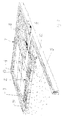
Fig. 2 is a perspective sketch of the foundation inFig. 1 during construction, the line I-I indicating the cross-section inFig. 1 . - A foundation according to the invention including a
load distribution layer 1 and aninsulating layer 2 composed oflamella elements 3 withcover elements 4 on top is shown inFig. 1 . The lamella elements are laid out directly onto acapillary barrier 5 isolating them from theground 6. Aplinth 7 intended for supporting a load bearing structure (not shown) of for example a building defines the outer boundaries of the foundation. In this embodiment theplinth 7 is composed of afoundation block 71 made from concrete and twolayers 72 of insulated foundation blocks made from aircrete with a filling of a foamed plastic serving as insulation. - The foundation may include further features such as capillary barriers on the outer side of the
plinth 7, but as such features will be readily imaginable to the skilled person and are not of consequence for the present invention, they will not be described here. Likewise, it is to be understood that the dimensions and construction of the features shown may vary depending for example of the loads to be carried by the foundation, the climate zone, soil conditions, local building traditions etc. without departing from the scope of the invention. - In the embodiment shown in
Fig. 1 , theload distribution layer 1 is made from concrete cast in-situ and is thus without joints, except for where it meets theplinth 7. This way of making the load distribution layer is well tested and works well under virtually all conditions, but alternatives such as precast concrete slabs, boards of wooden materials or composites may also be used. Materials having large coefficient of thermal expansion or which display large volume changes in response to changes in humidity should, however, be used with care. - The
lamella elements 3 and coverelements 4 are here made from stone wool. In the lamella elements the primary orientation of the fibres are vertical, while the cover elements are walkable stone wool boards with a relative high density at least at the upper side facing the load distribution layer. Details with regards to these materials will be described later. - Referring now also to
Fig. 2 , where the foundation is shown in a perspective view with only some of the lamella elements and cover elements laid, eachcover element 4 has a width WC, which is considerable larger the width WL of alamella element 3, here approximately seven times larger, and a length CL which is somewhat larger then the length LL of a lamella element, here 1½ times larger. The height of the cover elements HC is considerable smaller than the height of lamella elements HL, here constituting approximately 1/3 as may be seen inFig. 1 . These dimensions are intended only to illustrate one possible embodiment and it is to be understood that they may vary greatly depending for example on the material used for the cover element and considerations relating to manufacture, transportation and handling. Often the height of the cover elements will constitute only 1/10 of the height of the lamella elements or even less. - When the
lamella elements 3 and coverelements 4 are laid in a simple side-by-side and end-to-end pattern as here, this means that joints between the cover elements are present only over every seventh joint between lamella elements at the length sides and every third joint between end sides of the lamella elements. Other size-ratios between thelamella elements 3 and coverelements 4 will result in different patterns, where coinciding joints are more or less frequent. Alternatively, the cover elements may be given a different shape or arranged in a different orientation so that the joints between them are not parallel to the joints between lamella elements, but this require a more complex production and/or laying technique and will therefore rarely be expedient. - Laying the lamella elements side-by-side and end-to-end as shown in
Fig. 2 is relatively easy. The workmen can simply start from thecorner 73, where the two sides of theplinth 7 meet and then lay the lamella elements close against each other until the entire area is covered. Some lamella elements and/or cover elements may, however, have to be cut to size to fit the area of the foundation as illustrated by the lamella elements in the row to the left inFig. 2 , which are only half as long as the others. It is of course possible to lay all lamella elements and to then cover them with cover elements, but it will usually be preferred to insulate an area of approximately 10 m2 with both lamella elements and cover elements and then continue with another section of similar size until the entire area of the foundation has been insulated. - When using lamella and cover elements made from stone wool, the materials used for insulating area of approximately 10 m2 corresponds to what can be loaded onto a standard pallet.
- Under normal conditions a side-by-side and end-to-end layout shown in the drawing will result in an insulating
layer 2 having satisfactory properties. However, if wanting to reduce the risk of the formation of thermal bridges, it will be advantageous to lay the lamella elements in a bond pattern resembling the pattern of the bricks in masonry, where the coinciding joints will be fewer or at least distributed more evenly. This reduces the risk of fresh concrete penetrating into the joint, where it may force the cover elements and/or lamella elements apart. - As mentioned above the
lamella elements 3 are made from stone wool, where the primary orientation of the fibres is vertical. This means that loads from theload distribution layer 1 affect the material substantially in parallel to the length axis of the fibres, where the strength is high, and that the stone wool with a relatively low density can thus be used. This reduces the loads to be carried by the workmen laying the lamella elements and has a positive impact on the insulating properties. In addition, the stone wool is characterized by a low deformation in compression in this direction, a factor which might otherwise potentially reduce the insulating properties. - Regarding the
cover elements 4, it is presently preferred that these are made from stone wool, but other materials may be employed as long as they are suited for contact with both the lamella elements and the load distribution layer, or at least provided with a surface layer that is. - In a preferred embodiment the cover elements are stone wool boards, where the orientation of the fibres is substantially in the plane of the layer of cover elements. This allows them to contribute to the load distribution and decrease the risk of cement sludge penetrating into the material. The cover elements are preferably of a somewhat higher density than the low density lamella elements and typically also board shape as opposed to the preferred rod-shape of the lamella elements. A density of the cover element of 130-230 kg/m3 as opposed to 90-220 kg/m3 for the lamella elements is preferred.
- Alternatively, to further increase the load distribution properties, the cover elements may be boards with an upper part having a density, which is higher than the density of a lower part arranged against the lamella elements. The exact densities of these two parts may vary, but it is preferred that the upper part has a density of 90-180 kg/m3, preferably 110-160 kg/m3, more preferred approximately 135 kg/m3, and that said lower part has a density of 65-125 kg/m3, preferably 80-110 kg/m3, more preferred approximately 95 kg/m3. The dimensions of the upper and lower parts may also vary depending on demands, but it is preferred that the upper part has a thickness of 3-50 mm, preferably 5-30 mm, more preferred approximately 10-20 mm, and that the lower part has a thickness of 10-60 mm, preferably 20-50 mm, more preferred approximately 30-40 mm.
- There need not be a sharp line between the upper and the lower part, meaning that the density may change gradually, and it is even possible to make boards, where the weight of the load distribution layer compresses the upper part to the desire density. Likewise it is to be understood that one or more further parts may be provided and that cover elements made of other materials than stone wool may also have two or more parts.
- As may be seen in
Fig. 2 , asteel wire mesh 8 is laid out on top of thecover elements 4. This mesh is intended to serve as reinforcement in a concrete layer, which is to be cast on top of the cover elements to serve as the load distribution layer. Preferably the reinforcement mesh is provided with spacers (not visible) on its underside to keep it at a distance above the cover elements so that the mesh will become completely embedded in the concrete. Spacers are preferably made from a material having a low thermal conductivity, such as plastic or concrete and may be integrated in the cover elements. They may be simple feet inserted between the mesh and the cover elements, resting on top of these, or they may be made to penetrate into the material of the cover elements, which will contribute to keeping them in place when the fresh concrete is poured over them. - Different features of the embodiments described above may be combined in other ways than those explicitly described and/or replace with alternatives without departing from the scope of the claims. As an example, two layers of cover elements may be provided on top of each without coinciding joints to prevent concrete from penetrating the insulating layer. Another example is the use of plastic sheets or the like at different levels in the foundation serving as moisture barriers, vapour barriers, concrete shuttering, load distributor or the like.
Claims (16)
- A method for insulating the foundation of a building, where a load distribution layer is made on top of an insulating layer, both layers covering the intended floor area of the building substantially entirely, characterized in that the formation of the insulating layer comprises the steps of:laying a plurality of lamella elements made from mineral wool close to one another with the primary orientation of the mineral wool fibres of the lamella elements being approximately vertical, andproviding one or more cover element(s) on top of the lamella elements to cover an upper surface of the lamella elements substantially entirely.
- A method according to claim 1, where the lamella elements are laid in a bond pattern and/or where the cover elements are laid so that at least some of the joints between them are not directly above parallel joints between lamella elements.
- A method according to claim 1 or 2, where the lamella elements and/or the cover elements are made of mineral wool, preferably having a density of more than 55 kg/m3.
- A method according to claim 3, where the cover elements are made from mineral wool having a density of 120-180 kg/m3.
- A method according to claim 3, where the cover elements are made from mineral wool and arranged with an upper part facing upwards and a lower part facing the lamella elements, said upper part having a density of 90-220 kg/m3, preferably 120-180 kg/m3, more preferred approximately 135-150 kg/m3, and a thickness of 3-50 mm, preferably 5-30 mm, more preferred approximately 10-20 mm, and said lower part having a density of 65-125 kg/m3, preferably 80-110 kg/m3, more preferred approximately 95 kg/m3, and a thickness of 10-60 mm, preferably 20-50 mm, more preferred approximately 30-40 mm.
- A method according to any one of the preceding claims, where the width of the lamella elements are 50-500 mm, preferably 100-400 mm, more preferred approximately 200-300 mm, the height of the lamella elements are 200-500 mm, and the length of the lamella elements are 1500-2500 mm, preferably preferred approximately 2000 mm, the height being the dimension, which is substantially parallel to the primary orientation of the mineral wool fibres and substantially vertical in the laid out state.
- A method according to any one of the preceding claims, where at least some of the lamella elements and/or cover elements are provided with a surface coating, such as an adhesive, a moisture repellent, a fungicide or a primer.
- A method according to any one of the preceding claims, where at least some of the cover elements are provided with spacers for concrete reinforcement.
- A foundation for a building comprising a load distribution layer on top of an insulating layer, both layers covering the floor area of the building substantially entirely, characterized in that the insulating layer comprises a plurality of lamella elements made from mineral wool lying closely adjacent to one another with the primary orientation of the mineral wool fibres of the lamella elements approximately vertical, and one or more cover elements on top of the lamella elements, covering them substantially entirely.
- A foundation according to claim 9, where the lamella elements lay in a bond pattern and/or where at least some of the joints between the cover elements are not directly above parallel joints between lamella elements.
- A foundation according to claim 9 or 10, where the lamella elements and/or the cover elements are made of mineral wool, preferably having a density of more than 55 kg/m3.
- A foundation according to claim 11, where the cover elements are made from mineral wool having a density of 120-180 kg/m3.
- A foundation according to claim 11, where the cover elements are made from mineral wool and each has an upper part facing upwards and a lower part facing the lamella elements, said upper part having a density of 90-220 kg/m3, preferably 120-180 kg/m3, more preferred approximately 135-150 kg/m3, and a thickness of 3-50 mm, preferably 5-30 mm, more preferred approximately 10-20 mm, and said lower part having a density of 65-125 kg/m3, preferably 80-110 kg/m3, more preferred approximately 95 kg/m3, and a thickness of 10-60 mm, preferably 20-50 mm, more preferred approximately 30-40 mm.
- A foundation according to any one of claims 9-13, where the width of the lamella elements are 50-500 mm, preferably 100-400 mm, more preferred approximately 200-300 mm, the height of the lamella elements are 200-500 mm and the length of the lamella elements are 1500-2500 mm, preferably 2000 mm, the height being the dimension, which is substantially parallel to the primary orientation of the mineral wool fibres and substantially vertical in the laid out state.
- A foundation according to any one of claims 9-14, where at least some of the lamella elements and/or cover elements have a surface coating, such as an adhesive, a moisture repellent, a fungicide or a primer.
- A foundation according to any one of claims 9-15, where the load distribution layer is made from concrete cast in-situ and/or where it further comprises a capillary barrier underneath the insulating layer.
Priority Applications (4)
| Application Number | Priority Date | Filing Date | Title |
|---|---|---|---|
| EP11173100A EP2543771A1 (en) | 2011-07-07 | 2011-07-07 | A method for insulating the foundation of a building and an insulated foundation |
| DK12732517.3T DK2729625T3 (en) | 2011-07-07 | 2012-06-29 | A METHOD FOR INSULATION OF THE FOUNDATION OF A BUILDING AND AN ISOLATED FOUNDATION |
| PCT/DK2012/050232 WO2013004237A1 (en) | 2011-07-07 | 2012-06-29 | A method for insulating the foundation of a building and an insulated foundation |
| EP12732517.3A EP2729625B1 (en) | 2011-07-07 | 2012-06-29 | A method for insulating the foundation of a building and an insulated foundation |
Applications Claiming Priority (1)
| Application Number | Priority Date | Filing Date | Title |
|---|---|---|---|
| EP11173100A EP2543771A1 (en) | 2011-07-07 | 2011-07-07 | A method for insulating the foundation of a building and an insulated foundation |
Publications (1)
| Publication Number | Publication Date |
|---|---|
| EP2543771A1 true EP2543771A1 (en) | 2013-01-09 |
Family
ID=45496592
Family Applications (2)
| Application Number | Title | Priority Date | Filing Date |
|---|---|---|---|
| EP11173100A Withdrawn EP2543771A1 (en) | 2011-07-07 | 2011-07-07 | A method for insulating the foundation of a building and an insulated foundation |
| EP12732517.3A Active EP2729625B1 (en) | 2011-07-07 | 2012-06-29 | A method for insulating the foundation of a building and an insulated foundation |
Family Applications After (1)
| Application Number | Title | Priority Date | Filing Date |
|---|---|---|---|
| EP12732517.3A Active EP2729625B1 (en) | 2011-07-07 | 2012-06-29 | A method for insulating the foundation of a building and an insulated foundation |
Country Status (3)
| Country | Link |
|---|---|
| EP (2) | EP2543771A1 (en) |
| DK (1) | DK2729625T3 (en) |
| WO (1) | WO2013004237A1 (en) |
Cited By (1)
| Publication number | Priority date | Publication date | Assignee | Title |
|---|---|---|---|---|
| WO2022220719A1 (en) * | 2021-04-13 | 2022-10-20 | Klara 500/1 Ab | A prefabricated construction foundation element, a method for manufacturing said foundation element and a method for building a construction foundation |
Families Citing this family (1)
| Publication number | Priority date | Publication date | Assignee | Title |
|---|---|---|---|---|
| SE543637C2 (en) * | 2019-12-08 | 2021-05-04 | Aid Ab | Module for assembling a load-bearing house foundation |
Citations (7)
| Publication number | Priority date | Publication date | Assignee | Title |
|---|---|---|---|---|
| DE3223246A1 (en) * | 1981-06-24 | 1983-01-13 | Österreichische Heraklith AG, 9702 Ferndorf, Kärnten | Multi-layer insulating slab and process for manufacture thereof |
| EP0130957A2 (en) * | 1983-06-30 | 1985-01-09 | Profoment Utvecklings Ab | Foundation for cellarless houses |
| FR2586051A1 (en) * | 1985-08-06 | 1987-02-13 | Gryga Jean | Prefabricated modular elements and assembly thereof for the construction of buildings |
| DE29714251U1 (en) * | 1997-07-31 | 1997-12-04 | Thueringer Daemmstoffwerke Gmb | Insulating element in composite design |
| WO2002035025A1 (en) * | 2000-10-25 | 2002-05-02 | Fletcher Building Holdings Limited | Floor structures |
| EP1666672A2 (en) * | 2004-10-06 | 2006-06-07 | Skanska Sverige AB | Building, foundation construction for a building and method of producing the same |
| WO2008155401A1 (en) * | 2007-06-20 | 2008-12-24 | Rockwool International A/S | Mineral fibre product |
-
2011
- 2011-07-07 EP EP11173100A patent/EP2543771A1/en not_active Withdrawn
-
2012
- 2012-06-29 EP EP12732517.3A patent/EP2729625B1/en active Active
- 2012-06-29 WO PCT/DK2012/050232 patent/WO2013004237A1/en active Application Filing
- 2012-06-29 DK DK12732517.3T patent/DK2729625T3/en active
Patent Citations (7)
| Publication number | Priority date | Publication date | Assignee | Title |
|---|---|---|---|---|
| DE3223246A1 (en) * | 1981-06-24 | 1983-01-13 | Österreichische Heraklith AG, 9702 Ferndorf, Kärnten | Multi-layer insulating slab and process for manufacture thereof |
| EP0130957A2 (en) * | 1983-06-30 | 1985-01-09 | Profoment Utvecklings Ab | Foundation for cellarless houses |
| FR2586051A1 (en) * | 1985-08-06 | 1987-02-13 | Gryga Jean | Prefabricated modular elements and assembly thereof for the construction of buildings |
| DE29714251U1 (en) * | 1997-07-31 | 1997-12-04 | Thueringer Daemmstoffwerke Gmb | Insulating element in composite design |
| WO2002035025A1 (en) * | 2000-10-25 | 2002-05-02 | Fletcher Building Holdings Limited | Floor structures |
| EP1666672A2 (en) * | 2004-10-06 | 2006-06-07 | Skanska Sverige AB | Building, foundation construction for a building and method of producing the same |
| WO2008155401A1 (en) * | 2007-06-20 | 2008-12-24 | Rockwool International A/S | Mineral fibre product |
Cited By (1)
| Publication number | Priority date | Publication date | Assignee | Title |
|---|---|---|---|---|
| WO2022220719A1 (en) * | 2021-04-13 | 2022-10-20 | Klara 500/1 Ab | A prefabricated construction foundation element, a method for manufacturing said foundation element and a method for building a construction foundation |
Also Published As
| Publication number | Publication date |
|---|---|
| EP2729625B1 (en) | 2019-04-03 |
| WO2013004237A1 (en) | 2013-01-10 |
| EP2729625A1 (en) | 2014-05-14 |
| DK2729625T3 (en) | 2019-06-11 |
Similar Documents
| Publication | Publication Date | Title |
|---|---|---|
| US6729090B2 (en) | Insulative building panel with transverse fiber reinforcement | |
| EP1192321B1 (en) | Integral concrete wall forming panel and method | |
| US7627997B2 (en) | Concrete foundation wall with a low density core and carbon fiber and steel reinforcement | |
| EP3115523B1 (en) | Concrete panel, especially for composite floors, and a composite floor | |
| AU2009316945B2 (en) | Lightweight building structure produced by using a mortar and a method for the production | |
| US3673750A (en) | Bottom for buildings without basement, and a method of making such bottom | |
| EA017390B1 (en) | Sloping roof system and insulating board for sloping roof systems | |
| CN106996152A (en) | One kind point embedded heat insulating and sound insulating floor and its construction method | |
| WO2002101164A1 (en) | Masonry block constructions with polymeric coating | |
| EP2543771A1 (en) | A method for insulating the foundation of a building and an insulated foundation | |
| CA2303913A1 (en) | Drainage and ventilation system for building wall assemblies | |
| CN207376876U (en) | A kind of damp-proofing wall | |
| PL204114B1 (en) | Flat or flat inclined roof construction and associated insulating element | |
| AU2014252765B2 (en) | Slab construction | |
| NL1012339C2 (en) | Floor, preferably a renovation floor for buildings, contains lightweight support beams comprising a fibrous material embedded in a polymer matrix | |
| EP2572061A1 (en) | An insulation piece, a method for insulating and an insulation package | |
| JP2724017B2 (en) | Waterproof layer protective flooring | |
| RU2160347C1 (en) | Multistory building | |
| EP3423646B1 (en) | Base floor of a building and a method for construction of a base of a building | |
| KR100648469B1 (en) | A panel and manufacturing method of it's | |
| Fausti et al. | Building acoustics throughout Europe Volume 1: Towards a common framework in building acoustics throughout Europe | |
| RU53329U1 (en) | WALL-MOUNTING ELEMENT AND BUILDING STRUCTURE | |
| AU772991B2 (en) | Integral concrete wall forming system | |
| AU2002256579B2 (en) | Masonry block constructions with polymeric coating | |
| RU48338U1 (en) | EXTERIOR HANGED WALL OF A FRAMEED MULTI-STOREY BUILDING |
Legal Events
| Date | Code | Title | Description |
|---|---|---|---|
| PUAI | Public reference made under article 153(3) epc to a published international application that has entered the european phase |
Free format text: ORIGINAL CODE: 0009012 |
|
| AK | Designated contracting states |
Kind code of ref document: A1 Designated state(s): AL AT BE BG CH CY CZ DE DK EE ES FI FR GB GR HR HU IE IS IT LI LT LU LV MC MK MT NL NO PL PT RO RS SE SI SK SM TR |
|
| AX | Request for extension of the european patent |
Extension state: BA ME |
|
| STAA | Information on the status of an ep patent application or granted ep patent |
Free format text: STATUS: THE APPLICATION IS DEEMED TO BE WITHDRAWN |
|
| 18D | Application deemed to be withdrawn |
Effective date: 20130710 |