EP2543745A1 - Method for controlling solids/liquid decant unit operations and systems - Google Patents
Method for controlling solids/liquid decant unit operations and systems Download PDFInfo
- Publication number
- EP2543745A1 EP2543745A1 EP11172794A EP11172794A EP2543745A1 EP 2543745 A1 EP2543745 A1 EP 2543745A1 EP 11172794 A EP11172794 A EP 11172794A EP 11172794 A EP11172794 A EP 11172794A EP 2543745 A1 EP2543745 A1 EP 2543745A1
- Authority
- EP
- European Patent Office
- Prior art keywords
- controller
- underflow
- flow
- counter
- solids
- Prior art date
- Legal status (The legal status is an assumption and is not a legal conclusion. Google has not performed a legal analysis and makes no representation as to the accuracy of the status listed.)
- Withdrawn
Links
- 239000007787 solid Substances 0.000 title claims abstract description 81
- 238000000034 method Methods 0.000 title claims abstract description 65
- 239000007788 liquid Substances 0.000 title claims abstract description 33
- 238000010977 unit operation Methods 0.000 title description 42
- 239000002562 thickening agent Substances 0.000 claims abstract description 61
- 239000002002 slurry Substances 0.000 claims abstract description 54
- 230000008569 process Effects 0.000 claims abstract description 41
- 238000002386 leaching Methods 0.000 claims abstract description 14
- 238000010908 decantation Methods 0.000 claims abstract description 11
- 238000012544 monitoring process Methods 0.000 claims abstract description 11
- 239000003795 chemical substances by application Substances 0.000 claims abstract description 6
- 239000007864 aqueous solution Substances 0.000 claims abstract description 5
- 230000006872 improvement Effects 0.000 claims abstract description 3
- XLYOFNOQVPJJNP-UHFFFAOYSA-N water Substances O XLYOFNOQVPJJNP-UHFFFAOYSA-N 0.000 claims description 18
- 230000007423 decrease Effects 0.000 claims description 15
- 229910052751 metal Inorganic materials 0.000 claims description 10
- 239000002184 metal Substances 0.000 claims description 10
- 239000008394 flocculating agent Substances 0.000 claims description 5
- 238000011084 recovery Methods 0.000 claims description 4
- 238000005516 engineering process Methods 0.000 claims description 3
- 150000002739 metals Chemical class 0.000 claims description 2
- 238000000926 separation method Methods 0.000 description 18
- 239000000243 solution Substances 0.000 description 14
- 238000010790 dilution Methods 0.000 description 7
- 239000012895 dilution Substances 0.000 description 7
- 239000000203 mixture Substances 0.000 description 7
- 230000004044 response Effects 0.000 description 5
- RYGMFSIKBFXOCR-UHFFFAOYSA-N Copper Chemical compound [Cu] RYGMFSIKBFXOCR-UHFFFAOYSA-N 0.000 description 4
- 229910052802 copper Inorganic materials 0.000 description 4
- 239000010949 copper Substances 0.000 description 4
- 238000000638 solvent extraction Methods 0.000 description 4
- 230000003247 decreasing effect Effects 0.000 description 3
- 238000005406 washing Methods 0.000 description 3
- XEEYBQQBJWHFJM-UHFFFAOYSA-N Iron Chemical compound [Fe] XEEYBQQBJWHFJM-UHFFFAOYSA-N 0.000 description 2
- PXHVJJICTQNCMI-UHFFFAOYSA-N Nickel Chemical compound [Ni] PXHVJJICTQNCMI-UHFFFAOYSA-N 0.000 description 2
- 239000012190 activator Substances 0.000 description 2
- 239000008346 aqueous phase Substances 0.000 description 2
- 230000015572 biosynthetic process Effects 0.000 description 2
- 230000008859 change Effects 0.000 description 2
- 238000006243 chemical reaction Methods 0.000 description 2
- 238000004090 dissolution Methods 0.000 description 2
- 238000009854 hydrometallurgy Methods 0.000 description 2
- 230000007246 mechanism Effects 0.000 description 2
- 239000012071 phase Substances 0.000 description 2
- 230000001737 promoting effect Effects 0.000 description 2
- 230000009467 reduction Effects 0.000 description 2
- 238000011144 upstream manufacturing Methods 0.000 description 2
- 101150030337 CCD7 gene Proteins 0.000 description 1
- 238000013019 agitation Methods 0.000 description 1
- 238000010936 aqueous wash Methods 0.000 description 1
- 238000001444 catalytic combustion detection Methods 0.000 description 1
- 238000005345 coagulation Methods 0.000 description 1
- 230000015271 coagulation Effects 0.000 description 1
- 238000010586 diagram Methods 0.000 description 1
- 239000006185 dispersion Substances 0.000 description 1
- 238000000605 extraction Methods 0.000 description 1
- 230000002349 favourable effect Effects 0.000 description 1
- 238000005189 flocculation Methods 0.000 description 1
- 230000016615 flocculation Effects 0.000 description 1
- PCHJSUWPFVWCPO-UHFFFAOYSA-N gold Chemical compound [Au] PCHJSUWPFVWCPO-UHFFFAOYSA-N 0.000 description 1
- 229910052737 gold Inorganic materials 0.000 description 1
- 239000010931 gold Substances 0.000 description 1
- 230000003116 impacting effect Effects 0.000 description 1
- 229910052742 iron Inorganic materials 0.000 description 1
- 239000006194 liquid suspension Substances 0.000 description 1
- WPBNNNQJVZRUHP-UHFFFAOYSA-L manganese(2+);methyl n-[[2-(methoxycarbonylcarbamothioylamino)phenyl]carbamothioyl]carbamate;n-[2-(sulfidocarbothioylamino)ethyl]carbamodithioate Chemical compound [Mn+2].[S-]C(=S)NCCNC([S-])=S.COC(=O)NC(=S)NC1=CC=CC=C1NC(=S)NC(=O)OC WPBNNNQJVZRUHP-UHFFFAOYSA-L 0.000 description 1
- 239000000463 material Substances 0.000 description 1
- 238000002156 mixing Methods 0.000 description 1
- 229910052759 nickel Inorganic materials 0.000 description 1
- 230000003134 recirculating effect Effects 0.000 description 1
- 239000013049 sediment Substances 0.000 description 1
- 239000000725 suspension Substances 0.000 description 1
- 230000007474 system interaction Effects 0.000 description 1
Images
Classifications
-
- C—CHEMISTRY; METALLURGY
- C22—METALLURGY; FERROUS OR NON-FERROUS ALLOYS; TREATMENT OF ALLOYS OR NON-FERROUS METALS
- C22B—PRODUCTION AND REFINING OF METALS; PRETREATMENT OF RAW MATERIALS
- C22B3/00—Extraction of metal compounds from ores or concentrates by wet processes
- C22B3/02—Apparatus therefor
-
- B—PERFORMING OPERATIONS; TRANSPORTING
- B01—PHYSICAL OR CHEMICAL PROCESSES OR APPARATUS IN GENERAL
- B01D—SEPARATION
- B01D21/00—Separation of suspended solid particles from liquids by sedimentation
- B01D21/30—Control equipment
- B01D21/32—Density control of clear liquid or sediment, e.g. optical control ; Control of physical properties
-
- B—PERFORMING OPERATIONS; TRANSPORTING
- B01—PHYSICAL OR CHEMICAL PROCESSES OR APPARATUS IN GENERAL
- B01D—SEPARATION
- B01D21/00—Separation of suspended solid particles from liquids by sedimentation
- B01D21/30—Control equipment
- B01D21/34—Controlling the feed distribution; Controlling the liquid level ; Control of process parameters
-
- C—CHEMISTRY; METALLURGY
- C02—TREATMENT OF WATER, WASTE WATER, SEWAGE, OR SLUDGE
- C02F—TREATMENT OF WATER, WASTE WATER, SEWAGE, OR SLUDGE
- C02F11/00—Treatment of sludge; Devices therefor
- C02F11/12—Treatment of sludge; Devices therefor by de-watering, drying or thickening
- C02F11/14—Treatment of sludge; Devices therefor by de-watering, drying or thickening with addition of chemical agents
-
- C—CHEMISTRY; METALLURGY
- C22—METALLURGY; FERROUS OR NON-FERROUS ALLOYS; TREATMENT OF ALLOYS OR NON-FERROUS METALS
- C22B—PRODUCTION AND REFINING OF METALS; PRETREATMENT OF RAW MATERIALS
- C22B3/00—Extraction of metal compounds from ores or concentrates by wet processes
- C22B3/04—Extraction of metal compounds from ores or concentrates by wet processes by leaching
-
- C—CHEMISTRY; METALLURGY
- C22—METALLURGY; FERROUS OR NON-FERROUS ALLOYS; TREATMENT OF ALLOYS OR NON-FERROUS METALS
- C22B—PRODUCTION AND REFINING OF METALS; PRETREATMENT OF RAW MATERIALS
- C22B3/00—Extraction of metal compounds from ores or concentrates by wet processes
- C22B3/20—Treatment or purification of solutions, e.g. obtained by leaching
-
- C—CHEMISTRY; METALLURGY
- C02—TREATMENT OF WATER, WASTE WATER, SEWAGE, OR SLUDGE
- C02F—TREATMENT OF WATER, WASTE WATER, SEWAGE, OR SLUDGE
- C02F1/00—Treatment of water, waste water, or sewage
- C02F1/52—Treatment of water, waste water, or sewage by flocculation or precipitation of suspended impurities
- C02F1/5209—Regulation methods for flocculation or precipitation
-
- C—CHEMISTRY; METALLURGY
- C02—TREATMENT OF WATER, WASTE WATER, SEWAGE, OR SLUDGE
- C02F—TREATMENT OF WATER, WASTE WATER, SEWAGE, OR SLUDGE
- C02F2103/00—Nature of the water, waste water, sewage or sludge to be treated
- C02F2103/10—Nature of the water, waste water, sewage or sludge to be treated from quarries or from mining activities
-
- Y—GENERAL TAGGING OF NEW TECHNOLOGICAL DEVELOPMENTS; GENERAL TAGGING OF CROSS-SECTIONAL TECHNOLOGIES SPANNING OVER SEVERAL SECTIONS OF THE IPC; TECHNICAL SUBJECTS COVERED BY FORMER USPC CROSS-REFERENCE ART COLLECTIONS [XRACs] AND DIGESTS
- Y02—TECHNOLOGIES OR APPLICATIONS FOR MITIGATION OR ADAPTATION AGAINST CLIMATE CHANGE
- Y02P—CLIMATE CHANGE MITIGATION TECHNOLOGIES IN THE PRODUCTION OR PROCESSING OF GOODS
- Y02P10/00—Technologies related to metal processing
- Y02P10/20—Recycling
Definitions
- the present invention belongs to the area of hydrometallurgy, and in particular to the leaching of ores and refers to an improved control basis for reducing un-optimized operating conditions in liquid/solid decant unit operations and systems.
- US 3,685,654 discloses a thickener for the concentration of a solids-liquid suspension includes a vessel or tank into which such a suspension is continuously introduced and a rotating rake assembly for exerting mechanical pressure on the solids-sediment layer settling in the bottom of the vessel.
- US 5,601,704 refers to an automatic feedback control system for a water treatment apparatus, such as a recirculating solids contact clarifier, that maintains steady-state operation of the clarifier by accurately measuring the concentration of suspended solids at designated portions of the clarifier and automatically adjusting clarifier variables to maintain optimum conditions despite changes in the inlet flow rate, composition or temperature.
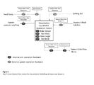
- Figure 1 depicts a simplified flow sheet of mechanized solids/liquid separation decantation system using a settling aid to facilitate solids/liquid separation of feed slurry as it is known from the state of the art.
- the system receives volume and mass information on feed slurry, settling aid and aqueous wash solution and controls the system aqueous overflow and the underflow slurry based on rake torque, rake height, bed mass and bed level.
- Typical indicating transmitters that can be used by operations as controller-systems and circuit inputs to affect favourable control are shown on the various feed and discharge systems. Indicating transmitters associated directly with the safe mechanical operation of the solid liquid separation decantation unit operation are also shown.
- Table 1 lists the various unit operation controllers, systems and circuits depicted in Figure 1 , and typical application of these components in operating philosophies employed by hydrometallurgical processing plants for solids/liquid separation decantation unit operations and circuits.
- Table 1 Operation Controllers System Controller component Typical Indicating Transmitter Feedback Typical operating philosophies Description of data manipulation Feed Slurry Volume/Mass flow meter Field and control room PLC (Process Logic Controller) feedback from instrument Manual control of feed slurry flow Operator-adjusted slurry feed pump or control valve output to required slurry mass/ volume throughput from a PLC Manual control of settling aid flow Operator-adjusted settling aid pump / control valve output to accommodate adjustment on feed slurry volume/ mass flow Feed slurry (Cont.) Densitometer Field and control room PLC feed-back from instrument Manual control of settling aid flow Operator-adjusted settling aid pump / control valve output to accommodate increase or decrease in feed slurry density and flow (mass flow) Set
- Unit operation Bed Level Bed Level Transmitter Manual interface of underflow slurry flow control adjustment Operator adjusted settling aid dosing pump output to affect an increase or decrease in bed level.
- the level of operator intervention for the above control scenario is high. This often results in metal extraction operations that utilize liquid/solid decant unit operations or systems, running at un-optimized states for high percentages of total operational run time. In addition to this, the potential for the total liquid/solid decant system to reach unsustainable operating conditions, where either a unit operation or a total system needs to be taken off the line, is high.
- the problem underlying the present invention has been to ensure a target liquid-solid separation process underflow slurry composition and an overflow solution composition that are achieved consistently with associated maximum mass transfer of the target phases, while not impacting negatively on any of the associated liquid/solid separation process unit operations, i. e. maximizing plant availability by reducing unplanned downtime due to mechanical failure of equipment.
- the present invention aims to provide a reliable control basis that can significantly reduce un-optimised operating conditions in liquid/solid decant unit operations and systems.
- the present invention refers to a method for dewatering a slurry from the leaching of a valuable ore with an aqueous solution of an effective leaching agent via a solids/liquid decantation system, providing an overflow depleted from solids and an underflow rich in solids that is washed counter-current through a number of solids/liquid decantation stages, the improvement implementing into the process line
- the method according to the present invention provides a reliable control basis that can significantly reduce un-optimised operating conditions in liquid/solid decant unit operations and systems.
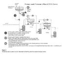
- FIG. 2 showing a simplified diagram highlighting the various controllers around the proposed solids/liquid separator decanter control basis.
- the identified unit operations being discussed are sequentially for the leach product thickener, and then for the Counter-Current Decanter 1 (CCD1), with system interaction control from the leach circuit and Counter-Current Decanter 2 (CCD2).
- CCD1 Counter-Current Decanter 1
- CCD2 Counter-Current Decanter 2
- the present invention refers to a method according to which said first Controller (C1) monitors and steers the flow and the density of the leach product thickener underflow and the dosing of the flocculants.
- Monitoring of the flow of the leach product underflow is preferably conducted by controlling the minimum thickener underflow discharge flow.
- said first Controller (C1) activates a Linear Flow Intervention Controller 1 (LFIC1) that increases the wash water flow output until the minimum product thickener underflow discharge flow is above the required minimum.
- LFIC1 Linear Flow Intervention Controller 1
- the control philosophy for the leach product thickener underflow flow control uses the minimum thickener underflow discharge flow, required to ensure slurry discharge linear (line) velocity is maintained above the minimum solids settling velocity (predetermined for process-specific slurry).
- a minimum linear flow intervention controller is activated.
- the Linear Flow Intervention Controller activates the wash water control valve to increase wash water flow output until the minimum product thickener underflow discharge flow is above the required minimum.
- the intervention controller remains active for as long as the pump is not available or pump output is at maximum.
- Monitoring of the density of the leach product underflow is preferably conducted by a densitometer and an in-line control valve.
- said first Controller (C1) activates a Leach Product Thickener Flocculent Dosing Controller (LPT-FDC1) that increases the output of the Leach Product Thickener Flocculent Dosing Pump (LPT-FDP1) until the product thickener underflow density increases to affect the underflow density control valve opening and the output is above the process defined minimum.
- LPT-FDC1 Leach Product Thickener Flocculent Dosing Controller
- the leach product thickener underflow density is automatically controlled around a process-defined set point, by controlled addition of wash solution into the suction line of the Leach Product Thickener Underflow Discharge Pump.
- the mechanism of control is by way of an in-line control valve.
- the underflow density controller In order to maintain target underflow pump discharge densities and to prevent unnecessary dilution of the advance slurry to the next unit operation, the underflow density controller requires leach product thickener underflow densities exiting the thickener, prior to wash solution addition, to be slightly higher than the "dilution-addition" underflow density control set point. This is achieved by including a fall-back default status for the product thickener flocculent dosing controller.
- the Product Thickener Flocculent Dosing Controller will incrementally ramp up the output of the product thickener flocculent dosing pump, until the product thickener underflow density increases to affect the underflow density control valve (wash water addition valve) opening. Once the density control valve output is above the process-defined minimum, flocculent dosing control reverts back to the product thickener flocculent dosing master controller.
- the flocculent dosing intervention controller will also ensure that thickener upset conditions promoting sliming (ineffective solid bed formation), is also addressed, as, under these conditions, target underflow densities will not be achieved, resulting in the underflow density control valve (wash valve) remaining closed.
- Dosing of the leach product flocculent is preferably monitored by the leach solids mass flow.
- said Controller activates said Leach Product Thickener Flocculent Dosing Controller (LPT-FDC1) that increases or decreases the output of the Leach Product Thickener Flocculent Dosing Pump (LPT-FDP1) until the set point of the feed solids mass flow is reached again.
- LPT-FDC1 Leach Product Thickener Flocculent Dosing Controller
- the leach product thickener flocculent dosing master controller uses the leach feed solids mass flow as the reference for product thickener flocculent dosing pump output.
- the process-specific flocculent dosing rate per unit mass of feed solids and the input concentration of made-up flocculent determine the required flow rate of flocculent per mass flow of solids fed into the leach product thickener.
- the leach product thickener wash water control valve output deviates from the process specified conditions, the leach product thickener flocculent dosing controller will increase or decrease the output of the flocculent dosing pump around the feed solids mass flow feedback set point.
- the reference mass flow is calculated from the leach feed volumetric flow meter and leach feed densitometer.
- a decrease of flocculent addition flow rate is included in the controller for this process condition. Due to the leach product thickener receiving all leach product slurry and no counter current-washing occurring for this unit operation, no thickener overflow control is necessary.
- said second Controller monitors and steers the flow and the density of the counter-current decanter underflow, the dosing of the flocculants and the flow of the counter-current decanter overflow.
- CCD1 is used for the counter-current decanter which is the first in a line of up to 10 separation units.
- Monitoring of the flow of the counter-current decanter underflow is preferably conducted by controlling the minimum counter-current decanter underflow discharge flow.
- said second Controller activates a Linear Flow Intervention Controller 1 (LFIC2) that increases the wash water flow output until the minimum counter-current decanter underflow discharge flow is above the required minimum.
- LFIC2 Linear Flow Intervention Controller 1
- CCD1 underflow flow control uses the minimum CCD1 underflow discharge flow, required to ensure slurry discharge linear (line) velocity is maintained above the minimum solids settling velocity (predetermined for process-specific slurry).
- Minimum Linear Flow Intervention Control In the event that the slurry discharge flow falls below the calculated minimum to prevent solids settling out ( ⁇ minimum linear velocity), and the pump output is at maximum, or the CCD1 underflow pump is stopped or tripped, a minimum linear flow intervention controller is activated. The linear flow intervention controller activates the wash water control valve to increase wash water flow output until the minimum CCD1 underflow discharge flow is above the required minimum. The intervention controller remains active for as long as the pump is not available or pump output is at maximum.
- Monitoring of the density of the counter-current decanter underflow is preferably conducted by a densitometer and an in-line control valve.
- said second Controller activates a Counter-Current Decanter Flocculent Dosing Controller (CCD-FDC2) that increases the output of the Counter-Current Decanter Flocculent Dosing Pump (CCD-FDP2) until the counter-current decanter underflow density increases to affect the underflow density control valve opening and the output is above the process defined minimum.
- C2 Counter-Current Decanter Flocculent Dosing Controller
- CCD-FDP2 Counter-Current Decanter Flocculent Dosing Pump
- the CCD1 underflow density is automatically controlled around a process-defined set point, by controlled addition of a bleed stream of CCD2 - the second decanter in line - overflow solution (which forms the wash solution in this case), into the suction line of the CCD1 underflow discharge pump.
- the mechanism of control is by way of an in-line control valve.
- the underflow density controller In order to maintain target underflow pump discharge densities and to prevent unnecessary dilution of the advance slurry to the next unit operation, the underflow density controller requires CCD1 underflow densities exiting the CCD, prior to wash solution addition, to be slightly higher than the "dilution addition" underflow density control set point. This is achieved by including a fall-back default status for the CCD1 flocculent dosing controller.
- the CCD1 flocculent dosing controller will incrementally ramp up the output of the CCD1 flocculent dosing pump, until the CCD1 underflow density increases to affect the underflow density control valve (wash water addition valve) opening. Once the density control valve output is above the process defined minimum, flocculent dosing control reverts back to the CCD1 flocculent dosing master controller.
- the flocculent dosing intervention controller will also ensure that counter-current decanter upset conditions promoting sliming (ineffective solid bed formation), is also addressed, as, under these conditions, target underflow densities will not be achieved, resulting in the underflow density control valve (wash valve) remaining closed.
- Dosing of the leach product flocculent is preferably monitored by the leach thickener underflow solids mass flow.
- said second Controller activates said Counter-Current Decanter Flocculent Dosing Controller (CCD-FDC1) that increases or decreases the output of the Counter-Current Decanter Flocculent Dosing Pump (CCD-FDP1) until the set point of the leach product thickener underflow solids mass flow is reached again.
- the CCD1 flocculent dosing master controller uses the leach thickener underflow solids mass flow as the reference for CCD1 flocculent dosing pump output.
- the process-specific flocculent dosing rate per unit mass of feed solids and the input concentration of made-up flocculent determine the required flow rate of flocculent per mass flow of solids into CCD1.
- the CCD1 wash water control valve output is above the process-specified minimum (ref 3.1.2)
- the CCD1 flocculent dosing controller will increase or decrease the output of the flocculent dosing pump around the leach product thickener underflow solids mass flow feedback.
- a decrease of flocculent addition flow rate is included in the controller for this process condition.
- Monitoring of the counter-current decanter overflow flow is preferably conducted by a flow meter.
- the output of the tank discharge pump (TDP) is adjusted accordingly.
- the present invention is incorporated into a leaching process for the recovery of valuable metals, in particular but not limited to copper, nickel, manganese, iron and gold, using the so-called split-circuit technology that is subject to US patent US 7,799,294 (Cognis ) which is incorporated by reference.
- the process encompasses
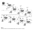
- Figure 3 shows a flow sheet for the recovery of copper by leach product slurry solids/liquid separation.
- the overflow reports to a high grade (HG) copper solvent extraction circuit, while the underflow is washed counter-current through a number of solids/liquid separation decantation stages, using raffinate from the low grade copper solvent extraction circuit.
- the number of washing stages may vary from one process circuit to the next, however the control philosophy described for each unit operation is the same for any number of washing stages.
- the figure is also useful illustrating the overflow control (step b4):
- the CCD1 overflow flow is controlled around the low grade (LG) raffinate flow input at CCD 7.
- the output of the CCD 1 needle tank discharge pump is increased or decreased around the moving average flow from the CCD7 LG raffinate flow meter (wash water flow meter).
- the moving average ensures smoother controller step changes around the flow controller output.
- the piping configuration for any CCD needle tank pump discharge is such that total discharge flow is measured prior to the off-take line for the underflow bleed wash line.
- the CCD1 overflow includes an intervention controller linked to the CCD1 level transmitter.
Landscapes
- Chemical & Material Sciences (AREA)
- Engineering & Computer Science (AREA)
- Organic Chemistry (AREA)
- Life Sciences & Earth Sciences (AREA)
- Environmental & Geological Engineering (AREA)
- Manufacturing & Machinery (AREA)
- General Life Sciences & Earth Sciences (AREA)
- Geochemistry & Mineralogy (AREA)
- Geology (AREA)
- Chemical Kinetics & Catalysis (AREA)
- Materials Engineering (AREA)
- Mechanical Engineering (AREA)
- Metallurgy (AREA)
- Hydrology & Water Resources (AREA)
- Water Supply & Treatment (AREA)
- General Chemical & Material Sciences (AREA)
- Manufacture And Refinement Of Metals (AREA)
Abstract
(a) a first Controller (C1) for monitoring and steering the leach product thickener; and
(b) a second Controller (C2) for monitoring and steering the counter-current decanter
Description
- The present invention belongs to the area of hydrometallurgy, and in particular to the leaching of ores and refers to an improved control basis for reducing un-optimized operating conditions in liquid/solid decant unit operations and systems.
- The proper separation of liquids and solids belong to the key unit operations in hydrometallurgy in general and in leaching of crude ores with an aqueous solution of an effective leaching agent in particular. From the state of the art various solids/liquid separation processes are well known, as for example dewatering thickeners, counter-current decanters (CCD) or pinned bed clarifiers (PBC).
- For example
US 3,685,654 (Gordon Sherrit Mines ) discloses a thickener for the concentration of a solids-liquid suspension includes a vessel or tank into which such a suspension is continuously introduced and a rotating rake assembly for exerting mechanical pressure on the solids-sediment layer settling in the bottom of the vessel.US 5,601,704 (Graver ) refers to an automatic feedback control system for a water treatment apparatus, such as a recirculating solids contact clarifier, that maintains steady-state operation of the clarifier by accurately measuring the concentration of suspended solids at designated portions of the clarifier and automatically adjusting clarifier variables to maintain optimum conditions despite changes in the inlet flow rate, composition or temperature. - All these methods are combining mixing, settling and decanting steps with or without the assistance of settling aids like for example flocculation or coagulation agents. Typically, the processes are supported by any source of agitation or movement of the phases. However, existing processes still show serious drawbacks which can have a negative impact on the efficacy of the solids/liquid separation and therefore on the yield and conversion of the overall leaching process:
- (i) Dosing of the settling aids:
- Fluctuating solids composition in the feed slurry or fluctuations in the feed slurry volumetric flow often cause fluctuations in the overall solids/liquid separation process. Manual dosage rate estimates and adjustments and erratic fluctuations in dosing controller input reference parameters can cause erratic settling aid dosing pump output having a negative impact on the settling aid dosage mass flow. As a consequence the composition of the products leaving the solids/liquid separation is constantly changing and causing problems in the following steps of the recovery process.
- (ii) Underflow discharge slurry densities:
- Inaccurate or inconsistent settling aid dosage mass flow leads to fluctuating underflow discharge slurry densities. Again, inconsistency of the compositions is a major problem for processing the liquids in the following operations.
- (iii) Inefficient liberation of dissolved soluble metal species
- Low system underflow slurry densities, higher entrained solution content per underflow slurry unit volume, and inefficient feed solids dispersion within contact wash aqueous solution prior to solid settling are responsible for an unsatisfying liberation of dissolved soluble metal species from the slurry being treated-, into the separated aqueous phase of the liquid/solid unit operation.
- (iv) Inefficient dissolution of un-dissolved soluble metal species
- Incomplete conversion of the lixiviant-soluble available contained metal in leach feed and product material, often caused by unbalanced metal leaching system parameters, lead to unsatisfactory dissolution of soluble metal species, from the solids of the slurry being treated, into the aqueous phase of the liquid/solid unit operation.
-
Figure 1 depicts a simplified flow sheet of mechanized solids/liquid separation decantation system using a settling aid to facilitate solids/liquid separation of feed slurry as it is known from the state of the art. The system receives volume and mass information on feed slurry, settling aid and aqueous wash solution and controls the system aqueous overflow and the underflow slurry based on rake torque, rake height, bed mass and bed level. Typical indicating transmitters that can be used by operations as controller-systems and circuit inputs to affect favourable control are shown on the various feed and discharge systems. Indicating transmitters associated directly with the safe mechanical operation of the solid liquid separation decantation unit operation are also shown. - The following Table 1 lists the various unit operation controllers, systems and circuits depicted in
Figure 1 , and typical application of these components in operating philosophies employed by hydrometallurgical processing plants for solids/liquid separation decantation unit operations and circuits.Table 1 Operation Controllers System Controller component Typical Indicating Transmitter Feedback Typical operating philosophies Description of data manipulation Feed Slurry Volume/Mass flow meter Field and control room PLC (Process Logic Controller) feedback from instrument Manual control of feed slurry flow Operator-adjusted slurry feed pump or control valve output to required slurry mass/ volume throughput from a PLC Manual control of settling aid flow Operator-adjusted settling aid pump / control valve output to accommodate adjustment on feed slurry volume/ mass flow Feed slurry (Cont.) Densitometer Field and control room PLC feed-back from instrument Manual control of settling aid flow Operator-adjusted settling aid pump / control valve output to accommodate increase or decrease in feed slurry density and flow (mass flow) Settling Aid Volume/ Mass flow meter Field and control room PLC feed-back from instrument Manual interface of settling aid flow control adjustment Operator-adjusted settling aid pump / control valve output to accommodate increase or decrease in feed slurry density Aqueous Over-flow /Wash solution for upstream liquid/solid separation decanter Volume/ Mass flow meter Field and control room PLC feed-back from instrument Manual interface of overflow aqueous flow control adjustment Operator-adjusted overflow aqueous pump / control valve output to balance wash throughput through entire solids/liquid separation circuit. This is done primarily to maintain process water balance. System Under-flow Slurry Volume/ Mass flow meter Field and control room PLC feed-back from instrument Manual interface of underflow slurry flow control adjustment Operator-adjust underflow slurry pump output to affect underflow flow control. Densitometer Field and control room PLC feed-back from instrument Manual interface of underflow slurry flow control adjustment Operator-adjust underflow slurry pump output to affect underflow density control. Unit Operation: Rake Torque Rake torque indicator Field and control room PLC feed-back from instrument Manual interface of underflow slurry flow control adjustment Operator-adjust underflow slurry pump output to affect a reduction in rake torque. Rake torque indicator Field and control room PLC feed-back from instrument Manual interface of settling aid dosing control adjustment Operator-adjust settling aid dosing pump output to affect a reduction in rake torque. Rake torque indicator Field, control room PLC and unit operation local field PLC feedback from instrument Automated rake raise-lower adjustment Unit operation local field PLC initiates rake-raise-lower control Unit Operation: Bed Mass Bed Mass Pressure Transmitter Field and PLC feedback from instrument Manual interface of underflow slurry flow control adjustment Operator-adjusted under-flow slurry pump output to affect an increase or decrease in unit operation bed mass. Unit operation: Bed Level Bed Level Transmitter Manual interface of underflow slurry flow control adjustment Operator adjusted settling aid dosing pump output to affect an increase or decrease in bed level. - The level of operator intervention for the above control scenario is high. This often results in metal extraction operations that utilize liquid/solid decant unit operations or systems, running at un-optimized states for high percentages of total operational run time. In addition to this, the potential for the total liquid/solid decant system to reach unsustainable operating conditions, where either a unit operation or a total system needs to be taken off the line, is high.
- Therefore, an effective control of these criteria is key for running an efficient lixiviation process. In particular the problem underlying the present invention has been to ensure a target liquid-solid separation process underflow slurry composition and an overflow solution composition that are achieved consistently with associated maximum mass transfer of the target phases, while not impacting negatively on any of the associated liquid/solid separation process unit operations, i. e. maximizing plant availability by reducing unplanned downtime due to mechanical failure of equipment. More particularly, the present invention aims to provide a reliable control basis that can significantly reduce un-optimised operating conditions in liquid/solid decant unit operations and systems.
- The present invention refers to a method for dewatering a slurry from the leaching of a valuable ore with an aqueous solution of an effective leaching agent via a solids/liquid decantation system, providing an overflow depleted from solids and an underflow rich in solids that is washed counter-current through a number of solids/liquid decantation stages, the improvement implementing into the process line
- (a) a first Controller (C1) for monitoring and steering the leach product thickener; and
- (b) a second Controller (C2) for monitoring and steering the counter-current decanter.
- The method according to the present invention provides a reliable control basis that can significantly reduce un-optimised operating conditions in liquid/solid decant unit operations and systems.
- The invention is illustrated by
Figure 2 showing a simplified diagram highlighting the various controllers around the proposed solids/liquid separator decanter control basis. The identified unit operations being discussed are sequentially for the leach product thickener, and then for the Counter-Current Decanter 1 (CCD1), with system interaction control from the leach circuit and Counter-Current Decanter 2 (CCD2). - In order to avoid ambiguities the following control system nomenclature is defined and applicable to terminology associated with this patent application:
- (a) Indicating transmitter: Any instrument or device that gives feedback either as a local display in the field or to a central Process Logic Controller (PLC) (e.g. level transmitter, flow meter, densitometer, pH meter, pressure transmitter, temperature transmitter, turbidity meter).
- (b) Controller: Any device that receives an input signal either directly or indirectly from an indicating transmitter or PLC and responds accordingly by either increasing or decreasing the output of that device (e.g. pump variable speed controllers and drives, proportional output control valves).
- (c) Unit Operation: An installed item of equipment with associated drives and discharge system.
- (d) Unit Operation Control (UOC): Control integrally associated with any one unit operation. For example, the following list of indicating transmitters and controllers are associated with an agitated tank at unit operation level:
- Tank Level Transmitter
- Tank Temperature transmitter
- Tank Agitator Ammeter (Current transmitter)
- Tank Discharge Slurry Flow Transmitter
- Tank Discharge Slurry Densitometer
- Tank Discharge Slurry pump Variable Speed Drive
- (e) System: A group of unit operations that are integrally associated (both from a process and control perspective).
- (f) System Control: Control integrally associated with a group of associated unit operations. For example, the following list of indicating transmitters will affect a control response from the tank unit operation:
- Tank Feed Slurry Flow Transmitter (better referred to as Adjacent System Tank Discharge Slurry Flow Transmitter)
- Adjacent Unit Operation Tank Feed Slurry Pump Variable Speed Drive
- Adjacent Unit Operation Tank Discharge Slurry Flow Transmitter
- All the above indicating transmitters and controllers are either feedback indicators (supply information about the status of the process unit operation at any given time) or are controllers responding in a certain way to the feedback status of the process unit operation as provided by the feedback indicators.
- Tank Feed Slurry Flow Transmitter (better referred to as Adjacent System Tank Discharge Slurry Flow Transmitter)
- (g) Circuit: A collection of systems that respond to feedback indicators from associated systems. For example, the indicating level transmitter of a tank (unit operation) could be linked to an upstream feed tank discharge pump variable speed drive, causing the drive either to speed up or slow down, depending on a corresponding decrease or increase in tank (unit operation) level. Collectively the control of the two unit operations are referencing feedback indicators and implementing control outside the individual systems control.
Figure 1 shows typical indicating transmitters and controllers associated with a mechanical liquid/solid decantation unit operation or system. - (h) Primary control: This is the preferred or default control for any target controllable process parameter. Primary control is generally applicable when the unit operation, system or circuit control is within defined process limit parameters. (i.e. at a state of acceptable equilibrium). Rate of change (step changes) in control parameters for primary controllers is generally gentle (small).
- (i) Intervention control: These are controllers that are only activated when the unit operation, system or circuit parameters move outside the defined process limit parameters. Intervention controllers rate of change steps are large and are designed to bring the unit operation, system or circuit control back within defined process limit parameters with the minimum delay.
- In a preferred embodiment the present invention refers to a method according to which said first Controller (C1) monitors and steers the flow and the density of the leach product thickener underflow and the dosing of the flocculants.
- Monitoring of the flow of the leach product underflow is preferably conducted by controlling the minimum thickener underflow discharge flow. In case the slurry discharge flow falls below the calculated minimum to prevent solids settling out said first Controller (C1) activates a Linear Flow Intervention Controller 1 (LFIC1) that increases the wash water flow output until the minimum product thickener underflow discharge flow is above the required minimum.
- More precise, the control philosophy for the leach product thickener underflow flow control uses the minimum thickener underflow discharge flow, required to ensure slurry discharge linear (line) velocity is maintained above the minimum solids settling velocity (predetermined for process-specific slurry). In the event that the slurry discharge flow falls below the calculated minimum to prevent solids settling out (< minimum linear velocity), and the pump output is at maximum, or the underflow pump is stopped or tripped, a minimum linear flow intervention controller is activated. The Linear Flow Intervention Controller activates the wash water control valve to increase wash water flow output until the minimum product thickener underflow discharge flow is above the required minimum. The intervention controller remains active for as long as the pump is not available or pump output is at maximum. This ensures that in the event of the possibility of a partial or complete choke developing on the leach product thickener underflow line, there is a flush backup system to minimize the frequency of this occurring. The underflow discharge pump will increase or decrease back down to the minimum discharge flow in response to any increase in rake torque. Rake torque is the preferred underflow flow intervention control activator, but two additional parameters could also be considered as alternative intervention controller for underflow flow control:
- Rake height level transmitter (an increase in rake height will cause a proportional increase in underflow pump output).
- Bed mass pressure transmitter (an increase in bed mass pressure will cause a proportional increase in underflow pump output).
- Either of these alternatives can be used, however using the bed mass pressure transmitter as the preferred intervention controller is less preferred, due to the unreliability of bed mass pressure transmitters.
- Monitoring of the density of the leach product underflow is preferably conducted by a densitometer and an in-line control valve. In case the product thickener underflow density is less than a process specified minimum said first Controller (C1) activates a Leach Product Thickener Flocculent Dosing Controller (LPT-FDC1) that increases the output of the Leach Product Thickener Flocculent Dosing Pump (LPT-FDP1) until the product thickener underflow density increases to affect the underflow density control valve opening and the output is above the process defined minimum.
- More precise, the leach product thickener underflow density is automatically controlled around a process-defined set point, by controlled addition of wash solution into the suction line of the Leach Product Thickener Underflow Discharge Pump. The mechanism of control is by way of an in-line control valve. By controlling the underflow density by wash water dilution, fluctuations in thickener underflow density can be reduced, which in turn affords opportunity for tighter flocculent dosing master control. In order to maintain target underflow pump discharge densities and to prevent unnecessary dilution of the advance slurry to the next unit operation, the underflow density controller requires leach product thickener underflow densities exiting the thickener, prior to wash solution addition, to be slightly higher than the "dilution-addition" underflow density control set point. This is achieved by including a fall-back default status for the product thickener flocculent dosing controller. In the event that the product thickener underflow density control valve output is less than a process specified minimum (either determined by valve actuator position or by underflow wash flow meter), the Product Thickener Flocculent Dosing Controller will incrementally ramp up the output of the product thickener flocculent dosing pump, until the product thickener underflow density increases to affect the underflow density control valve (wash water addition valve) opening. Once the density control valve output is above the process-defined minimum, flocculent dosing control reverts back to the product thickener flocculent dosing master controller. The flocculent dosing intervention controller will also ensure that thickener upset conditions promoting sliming (ineffective solid bed formation), is also addressed, as, under these conditions, target underflow densities will not be achieved, resulting in the underflow density control valve (wash valve) remaining closed.
- Dosing of the leach product flocculent is preferably monitored by the leach solids mass flow. In case the flocculent dosing rate per unit mass of feed solids and the input concentration of made-up flocculants determining the required flow rate of flocculent per mass flow of solids fed into the leach product thickener, deviates from the process specified conditions, said Controller (C1) activates said Leach Product Thickener Flocculent Dosing Controller (LPT-FDC1) that increases or decreases the output of the Leach Product Thickener Flocculent Dosing Pump (LPT-FDP1) until the set point of the feed solids mass flow is reached again.
- More precise, the leach product thickener flocculent dosing master controller uses the leach feed solids mass flow as the reference for product thickener flocculent dosing pump output. The process-specific flocculent dosing rate per unit mass of feed solids and the input concentration of made-up flocculent, determine the required flow rate of flocculent per mass flow of solids fed into the leach product thickener. In the event that the leach product thickener wash water control valve output deviates from the process specified conditions, the leach product thickener flocculent dosing controller will increase or decrease the output of the flocculent dosing pump around the feed solids mass flow feedback set point. In the case of the leach product thickener, the reference mass flow is calculated from the leach feed volumetric flow meter and leach feed densitometer. In response to any increase in rake torque that will affect an increase in underflow pump speed a decrease of flocculent addition flow rate is included in the controller for this process condition. Due to the leach product thickener receiving all leach product slurry and no counter current-washing occurring for this unit operation, no thickener overflow control is necessary.
- In another embodiment of the present invention said second Controller (C2) monitors and steers the flow and the density of the counter-current decanter underflow, the dosing of the flocculants and the flow of the counter-current decanter overflow. In the following the abbreviation CCD1 is used for the counter-current decanter which is the first in a line of up to 10 separation units.
- Monitoring of the flow of the counter-current decanter underflow is preferably conducted by controlling the minimum counter-current decanter underflow discharge flow. In case the slurry discharge flow falls below the calculated minimum to prevent solids settling out said second Controller (C2) activates a Linear Flow Intervention Controller 1 (LFIC2) that increases the wash water flow output until the minimum counter-current decanter underflow discharge flow is above the required minimum.
- More precise, the control philosophy for CCD1 underflow flow control uses the minimum CCD1 underflow discharge flow, required to ensure slurry discharge linear (line) velocity is maintained above the minimum solids settling velocity (predetermined for process-specific slurry).Minimum Linear Flow Intervention Control: In the event that the slurry discharge flow falls below the calculated minimum to prevent solids settling out (< minimum linear velocity), and the pump output is at maximum, or the CCD1 underflow pump is stopped or tripped, a minimum linear flow intervention controller is activated. The linear flow intervention controller activates the wash water control valve to increase wash water flow output until the minimum CCD1 underflow discharge flow is above the required minimum. The intervention controller remains active for as long as the pump is not available or pump output is at maximum. This ensures that in the event of a partial or complete choke developing on the CCD1 underflow line, there is a flush backup system to minimize the frequency of this occurring. This could increase plant availability considerably. The CCD1 underflow discharge pump will increase or decrease back to the minimum discharge flow in response to any increase in CCD1 rake torque. Rake torque is the preferred underflow flow intervention control activator, but two additional parameters can also be considered as alternative intervention controller for underflow flow control:
- Rake height level transmitter (an increase in rake height will cause a proportional increase in underflow pump output).
- Bed mass pressure transmitter (an increase in bed mass pressure will cause a proportional increase in underflow pump output).
- Either of these alternatives can be used, however using the bed mass pressure transmitter as the preferred intervention controller is less preferred, due to the unreliability of bed mass pressure transmitters.
- Monitoring of the density of the counter-current decanter underflow is preferably conducted by a densitometer and an in-line control valve. In case the counter-current decanter underflow density is less than a process specified minimum said second Controller (C2) activates a Counter-Current Decanter Flocculent Dosing Controller (CCD-FDC2) that increases the output of the Counter-Current Decanter Flocculent Dosing Pump (CCD-FDP2) until the counter-current decanter underflow density increases to affect the underflow density control valve opening and the output is above the process defined minimum.
- For the example illustrated in
Figure 2 , the CCD1 underflow density is automatically controlled around a process-defined set point, by controlled addition of a bleed stream of CCD2 - the second decanter in line - overflow solution (which forms the wash solution in this case), into the suction line of the CCD1 underflow discharge pump. The mechanism of control is by way of an in-line control valve. By controlling the underflow density by wash water dilution, fluctuations in thickener underflow density can be reduced, which in turn affords opportunity for tighter flocculent dosing master control. In order to maintain target underflow pump discharge densities and to prevent unnecessary dilution of the advance slurry to the next unit operation, the underflow density controller requires CCD1 underflow densities exiting the CCD, prior to wash solution addition, to be slightly higher than the "dilution addition" underflow density control set point. This is achieved by including a fall-back default status for the CCD1 flocculent dosing controller. In the event that the CCD1 underflow density control valve output is less than a process-specified minimum (either determined by valve actuator position or by underflow wash flow meter), the CCD1 flocculent dosing controller will incrementally ramp up the output of the CCD1 flocculent dosing pump, until the CCD1 underflow density increases to affect the underflow density control valve (wash water addition valve) opening. Once the density control valve output is above the process defined minimum, flocculent dosing control reverts back to the CCD1 flocculent dosing master controller. The flocculent dosing intervention controller will also ensure that counter-current decanter upset conditions promoting sliming (ineffective solid bed formation), is also addressed, as, under these conditions, target underflow densities will not be achieved, resulting in the underflow density control valve (wash valve) remaining closed. - Dosing of the leach product flocculent is preferably monitored by the leach thickener underflow solids mass flow. In case the flocculent dosing rate per unit mass of feed solids and the input concentration of made-up flocculents determining the required flow rate of flocculent per mass flow of solids fed into the counter-current decanter, deviates from the process specified conditions, said second Controller (C2) activates said Counter-Current Decanter Flocculent Dosing Controller (CCD-FDC1) that increases or decreases the output of the Counter-Current Decanter Flocculent Dosing Pump (CCD-FDP1) until the set point of the leach product thickener underflow solids mass flow is reached again.
- More precise, the CCD1 flocculent dosing master controller uses the leach thickener underflow solids mass flow as the reference for CCD1 flocculent dosing pump output. The process-specific flocculent dosing rate per unit mass of feed solids and the input concentration of made-up flocculent determine the required flow rate of flocculent per mass flow of solids into CCD1. In the event that the CCD1 wash water control valve output is above the process-specified minimum (ref 3.1.2), the CCD1 flocculent dosing controller will increase or decrease the output of the flocculent dosing pump around the leach product thickener underflow solids mass flow feedback. In response to any increase in rake torque, that will affect an increase in underflow pump speed a decrease of flocculent addition flow rate is included in the controller for this process condition.
- Monitoring of the counter-current decanter overflow flow is preferably conducted by a flow meter. In case the level of aqueous overflow in the counter-current decanter tank moves outside process-defined battery conditions, the output of the tank discharge pump (TDP) is adjusted accordingly.
- In another preferred embodiment the present invention is incorporated into a leaching process for the recovery of valuable metals, in particular but not limited to copper, nickel, manganese, iron and gold, using the so-called split-circuit technology that is subject to
US patent US 7,799,294 (Cognis ) which is incorporated by reference. The process encompasses - (a) providing a first aqueous leach pulp which comprises a mixture of leached solids and an aqueous leach solution comprising a metal, a leaching agent and water;
- (b) subjecting the first aqueous leach pulp to a first solid-liquid separation to provide a first clarified aqueous leach solution and a second aqueous leach pulp, wherein the second aqueous leach pulp comprises the leached solids at a percent solids level greater than the first pulp;
- (c) subjecting the first clarified aqueous leach solution to a first solvent extraction prior to any significant dilution, whereby a first aqueous raffinate is obtained;
- (d) subjecting the second aqueous leach pulp to a second solid-liquid separation with dilution via an aqueous stream to obtain a second clarified aqueous leach solution; and
- (e) subjecting the second clarified aqueous leach solution to a second solvent extraction whereby a second aqueous raffinate is obtained.
-
Figure 3 shows a flow sheet for the recovery of copper by leach product slurry solids/liquid separation. In this case the overflow reports to a high grade (HG) copper solvent extraction circuit, while the underflow is washed counter-current through a number of solids/liquid separation decantation stages, using raffinate from the low grade copper solvent extraction circuit. The number of washing stages may vary from one process circuit to the next, however the control philosophy described for each unit operation is the same for any number of washing stages. - The figure is also useful illustrating the overflow control (step b4): The CCD1 overflow flow is controlled around the low grade (LG) raffinate flow input at CCD 7. The output of the CCD 1 needle tank discharge pump is increased or decreased around the moving average flow from the CCD7 LG raffinate flow meter (wash water flow meter). The moving average ensures smoother controller step changes around the flow controller output. The piping configuration for any CCD needle tank pump discharge is such that total discharge flow is measured prior to the off-take line for the underflow bleed wash line. The CCD1 overflow includes an intervention controller linked to the CCD1 level transmitter. In the event that the level of aqueous overflow in the CCD1 needle tank moves outside process-defined battery limit high and low levels, the CCD1 needle tank discharge pump output is increased or decreased accordingly. Once the CCD1 needle tank level returns to within the process-defined battery limits, control reverts back to the primary CCD1 overflow flow control.
- Similar control philosophies are prescribed for all additional downstream CCDs with the exception of the final CCD (in this example, CCD 7). The LG raffinate feed flow is rationed according to the total mass flow of leach product underflow solids feeding into CCD1.
Claims (18)
- In a method for dewatering a slurry from the leaching of a valuable ore with an aqueous solution of an effective leaching agent via a solids/liquid decantation system, providing an overflow depleted from solids and an underflow rich in solids that is washed counter-current through a number of solids/liquid decantation stages, the improvement implementing(a) a first Controller (C1) for monitoring and steering the leach product thickener; and(b) a second Controller (C2) for monitoring and steering the counter-current decanter.
- Method according to Claim 1, characterised in that said first Controller (C1) monitors and steers the flow and the density of the leach product thickener underflow and the dosing of the flocculants.
- Method according to Claim 2, characterised in that said first Controller (C1) monitors the flow of the leach product thickener underflow by controlling the minimum thickener underflow discharge flow.
- Methods according to Claims 2 and/or 3, characterised in that in case the slurry discharge flow falls below the calculated minimum to prevent solids settling out said first Controller (C1) activates a Linear Flow Intervention Controller 1 (LFIC1) that increases the wash water flow output until the minimum product thickener underflow discharge flow is above the required minimum.
- Method according to Claim 2, characterised in that said first Controller (C1) monitors the density of the leach product thickener underflow by a densitometer and an in-line control valve.
- Method according to Claims 2 and 5, characterised in that in case the product thickener underflow density is less than a process specified minimum said first Controller (C1) activates a Leach Product Thickener Flocculent Dosing Controller (LPT-FDC1) that increases the output of the Leach Product Thickener Flocculent Dosing Pump (LPT-FDP1) until the product thickener underflow density increases to affect the underflow density control valve opening and the output is above the process defined minimum.
- Method according to Claim 2, characterised in that said first Controller (C1) monitors the dosing of the leach product flocculent by the leach solids mass flow.
- Method according to Claims 2 and 7, characterised in that in case the flocculent dosing rate per unit mass of feed solids and the input concentration of made-up flocculents determining the required flow rate of flocculent per mass flow of solids fed into the leach product thickener, deviates from the process specified conditions, said first Controller (C1) activates said Leach Product Thickener Flocculent Dosing Controller (LPT-FDC1) that increases or decreases the output of the Leach Product Thickener Flocculent Dosing Pump (LPT-FDP1) until the set point of the feed solids mass flow is reached again.
- Method according to Claim 1, characterised in that said second Controller (C2) monitors and steers the flow and the density of the counter-current decanter underflow, the dosing of the flocculants and the flow of the counter-current decanter overflow.
- Method according to Claim 9, characterised in that second Controller (C2) monitors the flow of the counter-current decanter underflow by controlling the minimum counter-current decanter underflow discharge flow.
- Method according to Claims 9 and 10, characterised in that in case the slurry discharge flow falls below the calculated minimum to prevent solids settling out said second Controller (C2) activates a Linear Flow Intervention Controller 1 (LFIC2) that increases the wash water flow output until the minimum counter-current decanter underflow discharge flow is above the required minimum.
- Method according to Claim 9, characterised in that said second Controller (C2) monitors the density of the leach product thickener underflow by a densitometer and an in-line control valve.
- Method according to Claims 9 and 12, characterised in that in case the counter-current decanter underflow density is less than a process specified minimum said second Controller (C2) activates a Counter-Current Decanter Flocculent Dosing Controller (CCD-FDC2) that increases the output of the Counter-Current Decanter Flocculent Dosing Pump (CCD-FDP2) until the counter-current decanter underflow density increases to affect the underflow density control valve opening and the output is above the process defined minimum.
- Method according to Claim 9, characterised in that said second Controller (C2) monitors the dosing of counter-current decanter flocculent by the leach thickener underflow solids mass flow.
- Method according to Claims 9 and 14, characterised in that in case the flocculent dosing rate per unit mass of feed solids and the input concentration of made-up flocculents determining the required flow rate of flocculent per mass flow of solids fed into the counter-current decanter, deviates from the process specified conditions, said second Controller (C2) activates said Counter-Current Decanter Flocculent Dosing Controller (CCD-FDC1) that increases or decreases the output of the Counter-Current Decanter Flocculent Dosing Pump (CCD-FDP1) until the set point of the leach product thickener underflow solids mass flow is reached again.
- Method according to Claim 9, characterised in that said second Controller (C2) monitors the flow of the counter-current decanter overflow is monitored by a flow meter.
- Method according to Claims 9 and 16, characterised in that in case the level of aqueous overflow in the counter-current decanter tank moves outside process-defined battery conditions, the output of the tank discharge pump (TDP) is adjusted accordingly.
- Method according to any of the preceding Claims 1 to 17, characterised in that the control system is part of a leaching process for the recovery of valuable metals from ores using the so-called split-circuit technology.
Priority Applications (1)
| Application Number | Priority Date | Filing Date | Title |
|---|---|---|---|
| EP11172794A EP2543745A1 (en) | 2011-07-06 | 2011-07-06 | Method for controlling solids/liquid decant unit operations and systems |
Applications Claiming Priority (1)
| Application Number | Priority Date | Filing Date | Title |
|---|---|---|---|
| EP11172794A EP2543745A1 (en) | 2011-07-06 | 2011-07-06 | Method for controlling solids/liquid decant unit operations and systems |
Publications (1)
| Publication Number | Publication Date |
|---|---|
| EP2543745A1 true EP2543745A1 (en) | 2013-01-09 |
Family
ID=44533838
Family Applications (1)
| Application Number | Title | Priority Date | Filing Date |
|---|---|---|---|
| EP11172794A Withdrawn EP2543745A1 (en) | 2011-07-06 | 2011-07-06 | Method for controlling solids/liquid decant unit operations and systems |
Country Status (1)
| Country | Link |
|---|---|
| EP (1) | EP2543745A1 (en) |
Cited By (3)
| Publication number | Priority date | Publication date | Assignee | Title |
|---|---|---|---|---|
| CN107029530A (en) * | 2017-04-26 | 2017-08-11 | 北京清新环境技术股份有限公司 | A kind of container-type additive solution dosing system for flue gas demercuration |
| CN114534314A (en) * | 2022-03-22 | 2022-05-27 | 濮阳市盛源能源科技股份有限公司 | Water decanter series connection device |
| WO2026083376A1 (en) * | 2024-10-14 | 2026-04-23 | Pt Esg New Energy Material | A kind of hydrometallurgical pre-neutralization and real-time control system and method for lateritic nickel ore |
Citations (10)
| Publication number | Priority date | Publication date | Assignee | Title |
|---|---|---|---|---|
| US3106933A (en) * | 1958-12-13 | 1963-10-15 | Passavant Werke | Controlling liquid media including solid matter suspended therein |
| US3208592A (en) * | 1961-11-03 | 1965-09-28 | Saskatchewan Potash | Method of controlling hydroseparator operation |
| US3685654A (en) | 1971-03-22 | 1972-08-22 | Gordon Sherritt Mines Ltd | Thickener |
| US3731804A (en) * | 1971-01-18 | 1973-05-08 | Sherritt Gordon Mines Ltd | Control of sensity of thickener underflow slurry |
| US4096028A (en) * | 1976-11-26 | 1978-06-20 | Nalco Chemical Company | Feed forward control of dissolved solids in a countercurrent separation and washing zone |
| US4226714A (en) * | 1978-12-27 | 1980-10-07 | The Anaconda Company | Thickener control system |
| US5601704A (en) | 1994-04-11 | 1997-02-11 | The Graver Company | Automatic feedback control system for a water treatment apparatus |
| WO2000012192A1 (en) * | 1998-09-02 | 2000-03-09 | Malcolm David Thomas | Apparatus for the separation of solids and liquids |
| WO2000069780A1 (en) * | 1999-05-14 | 2000-11-23 | Sven Bernhardsson | Process control of the dewatering of sludge |
| US7799294B2 (en) | 2003-07-30 | 2010-09-21 | Cognis Ip Management Gmbh | Methods for improving the recovery of metal leaching agents |
-
2011
- 2011-07-06 EP EP11172794A patent/EP2543745A1/en not_active Withdrawn
Patent Citations (10)
| Publication number | Priority date | Publication date | Assignee | Title |
|---|---|---|---|---|
| US3106933A (en) * | 1958-12-13 | 1963-10-15 | Passavant Werke | Controlling liquid media including solid matter suspended therein |
| US3208592A (en) * | 1961-11-03 | 1965-09-28 | Saskatchewan Potash | Method of controlling hydroseparator operation |
| US3731804A (en) * | 1971-01-18 | 1973-05-08 | Sherritt Gordon Mines Ltd | Control of sensity of thickener underflow slurry |
| US3685654A (en) | 1971-03-22 | 1972-08-22 | Gordon Sherritt Mines Ltd | Thickener |
| US4096028A (en) * | 1976-11-26 | 1978-06-20 | Nalco Chemical Company | Feed forward control of dissolved solids in a countercurrent separation and washing zone |
| US4226714A (en) * | 1978-12-27 | 1980-10-07 | The Anaconda Company | Thickener control system |
| US5601704A (en) | 1994-04-11 | 1997-02-11 | The Graver Company | Automatic feedback control system for a water treatment apparatus |
| WO2000012192A1 (en) * | 1998-09-02 | 2000-03-09 | Malcolm David Thomas | Apparatus for the separation of solids and liquids |
| WO2000069780A1 (en) * | 1999-05-14 | 2000-11-23 | Sven Bernhardsson | Process control of the dewatering of sludge |
| US7799294B2 (en) | 2003-07-30 | 2010-09-21 | Cognis Ip Management Gmbh | Methods for improving the recovery of metal leaching agents |
Cited By (3)
| Publication number | Priority date | Publication date | Assignee | Title |
|---|---|---|---|---|
| CN107029530A (en) * | 2017-04-26 | 2017-08-11 | 北京清新环境技术股份有限公司 | A kind of container-type additive solution dosing system for flue gas demercuration |
| CN114534314A (en) * | 2022-03-22 | 2022-05-27 | 濮阳市盛源能源科技股份有限公司 | Water decanter series connection device |
| WO2026083376A1 (en) * | 2024-10-14 | 2026-04-23 | Pt Esg New Energy Material | A kind of hydrometallurgical pre-neutralization and real-time control system and method for lateritic nickel ore |
Similar Documents
| Publication | Publication Date | Title |
|---|---|---|
| US20130008856A1 (en) | Method For Controlling Solids/Liquid Decant Unit Operations And Systems | |
| CA1142453A (en) | Thickener control system | |
| Donegan | Direct solvent extraction of nickel at Bulong operations | |
| EP2957332B1 (en) | Solid-liquid-separation processing method, and hydrometallurgical method for nickel oxide ore | |
| JPH02500960A (en) | Method of leaching particulate solid material | |
| WO2018146371A1 (en) | Method and arrangement for controlling a dewatering process | |
| RU2730820C1 (en) | Method of extracting vanadium by countercurrent acid leaching of clinker from calcining firing | |
| CN112961981B (en) | Intensive large-scale ionic type rare earth ore leaching mother liquor continuous treatment system and method | |
| CN111050933B (en) | Method for desalting chlorine-containing powder and apparatus for desalting chlorine-containing powder | |
| CN113046580B (en) | Scandium extraction pretreatment system and treatment method of scandium-containing solution | |
| RU2672737C2 (en) | Method and device for liquid/solid separation such as dewatering particulate solids and agitation leaching | |
| CA2876564A1 (en) | Method for reprocessing an emulsion formed during hydrometallurgical recovery of a metal | |
| JP2015528854A5 (en) | ||
| JP2010285655A (en) | Metal recovery method | |
| CN215427456U (en) | Hydrometallurgy leaches rich liquid clarifier | |
| JP2023122850A (en) | Solid-liquid separation method using multistage thickner and wet smelter method of nickel oxide ore containing the same | |
| CN115999210A (en) | A Flocculant Automatic Addition Control Technology for Medium and Large Deep Cone Thickeners | |
| JP2019157236A (en) | Solid liquid separation treatment method, and wet refining method of nickel oxide ore | |
| CN1868879A (en) | Red mud separating washing technology with self circulation and its device | |
| US3573004A (en) | Countercurrent liquid-solids contact process | |
| Stanković et al. | Cementation of copper onto brass particles in a packed bed | |
| CN119876640B (en) | Method and system for controlling slurry concentration in high-pressure leaching of laterite nickel ore | |
| CN121537124B (en) | Method and system for treating tin stripping waste liquid by qualitative recovery of components | |
| Schwarz et al. | A case study on the operation of a Flottweg Tricanter® centrifuge for solvent-extraction crud treatment at Bwana Mkubwa, Ndola, Zambia | |
| Spence et al. | Practical aspects of copper solvent extraction from acidic leach liquors |
Legal Events
| Date | Code | Title | Description |
|---|---|---|---|
| PUAI | Public reference made under article 153(3) epc to a published international application that has entered the european phase |
Free format text: ORIGINAL CODE: 0009012 |
|
| AK | Designated contracting states |
Kind code of ref document: A1 Designated state(s): AL AT BE BG CH CY CZ DE DK EE ES FI FR GB GR HR HU IE IS IT LI LT LU LV MC MK MT NL NO PL PT RO RS SE SI SK SM TR |
|
| AX | Request for extension of the european patent |
Extension state: BA ME |
|
| 17P | Request for examination filed |
Effective date: 20130709 |
|
| RBV | Designated contracting states (corrected) |
Designated state(s): AL AT BE BG CH CY CZ DE DK EE ES FI FR GB GR HR HU IE IS IT LI LT LU LV MC MK MT NL NO PL PT RO RS SE SI SK SM TR |
|
| 17Q | First examination report despatched |
Effective date: 20160609 |
|
| STAA | Information on the status of an ep patent application or granted ep patent |
Free format text: STATUS: THE APPLICATION IS DEEMED TO BE WITHDRAWN |
|
| 18D | Application deemed to be withdrawn |
Effective date: 20161020 |