EP2543635A1 - System and method for recovering heat from co2 recovery device - Google Patents
System and method for recovering heat from co2 recovery device Download PDFInfo
- Publication number
- EP2543635A1 EP2543635A1 EP11739599A EP11739599A EP2543635A1 EP 2543635 A1 EP2543635 A1 EP 2543635A1 EP 11739599 A EP11739599 A EP 11739599A EP 11739599 A EP11739599 A EP 11739599A EP 2543635 A1 EP2543635 A1 EP 2543635A1
- Authority
- EP
- European Patent Office
- Prior art keywords
- heat
- recovery
- recovery unit
- boiler
- flue gas
- Prior art date
- Legal status (The legal status is an assumption and is not a legal conclusion. Google has not performed a legal analysis and makes no representation as to the accuracy of the status listed.)
- Withdrawn
Links
- 238000011084 recovery Methods 0.000 title claims abstract description 417
- 238000000034 method Methods 0.000 title claims description 52
- UGFAIRIUMAVXCW-UHFFFAOYSA-N Carbon monoxide Chemical compound [O+]#[C-] UGFAIRIUMAVXCW-UHFFFAOYSA-N 0.000 claims abstract description 127
- 239000003546 flue gas Substances 0.000 claims abstract description 125
- 230000002745 absorbent Effects 0.000 claims abstract description 89
- 239000002250 absorbent Substances 0.000 claims abstract description 89
- 239000006096 absorbing agent Substances 0.000 claims abstract description 30
- 238000010248 power generation Methods 0.000 claims description 45
- 239000012530 fluid Substances 0.000 claims description 11
- CURLTUGMZLYLDI-UHFFFAOYSA-N Carbon dioxide Chemical compound O=C=O CURLTUGMZLYLDI-UHFFFAOYSA-N 0.000 description 304
- 229910002092 carbon dioxide Inorganic materials 0.000 description 303
- 239000003570 air Substances 0.000 description 193
- 239000007789 gas Substances 0.000 description 130
- 239000000243 solution Substances 0.000 description 127
- 230000001172 regenerating effect Effects 0.000 description 64
- XLYOFNOQVPJJNP-UHFFFAOYSA-N water Substances O XLYOFNOQVPJJNP-UHFFFAOYSA-N 0.000 description 45
- QAOWNCQODCNURD-UHFFFAOYSA-N Sulfuric acid Chemical compound OS(O)(=O)=O QAOWNCQODCNURD-UHFFFAOYSA-N 0.000 description 40
- 238000011144 upstream manufacturing Methods 0.000 description 38
- 230000000694 effects Effects 0.000 description 32
- 230000003247 decreasing effect Effects 0.000 description 28
- 238000009833 condensation Methods 0.000 description 20
- 230000005494 condensation Effects 0.000 description 20
- 238000005260 corrosion Methods 0.000 description 20
- 230000007797 corrosion Effects 0.000 description 20
- 238000010586 diagram Methods 0.000 description 20
- 238000001816 cooling Methods 0.000 description 14
- NINIDFKCEFEMDL-UHFFFAOYSA-N Sulfur Chemical compound [S] NINIDFKCEFEMDL-UHFFFAOYSA-N 0.000 description 12
- 229910052717 sulfur Inorganic materials 0.000 description 12
- 239000011593 sulfur Substances 0.000 description 12
- 239000000498 cooling water Substances 0.000 description 10
- 239000012080 ambient air Substances 0.000 description 8
- 238000010992 reflux Methods 0.000 description 5
- -1 amine compound Chemical class 0.000 description 4
- 238000011010 flushing procedure Methods 0.000 description 4
- 238000010438 heat treatment Methods 0.000 description 3
- 239000002803 fossil fuel Substances 0.000 description 2
- 150000001412 amines Chemical class 0.000 description 1
- 239000007864 aqueous solution Substances 0.000 description 1
- 239000001569 carbon dioxide Substances 0.000 description 1
- 238000004140 cleaning Methods 0.000 description 1
- 239000000470 constituent Substances 0.000 description 1
- 239000000446 fuel Substances 0.000 description 1
- 150000003464 sulfur compounds Chemical class 0.000 description 1
- 238000010792 warming Methods 0.000 description 1
Images



Classifications
-
- B—PERFORMING OPERATIONS; TRANSPORTING
- B01—PHYSICAL OR CHEMICAL PROCESSES OR APPARATUS IN GENERAL
- B01D—SEPARATION
- B01D53/00—Separation of gases or vapours; Recovering vapours of volatile solvents from gases; Chemical or biological purification of waste gases, e.g. engine exhaust gases, smoke, fumes, flue gases, aerosols
- B01D53/14—Separation of gases or vapours; Recovering vapours of volatile solvents from gases; Chemical or biological purification of waste gases, e.g. engine exhaust gases, smoke, fumes, flue gases, aerosols by absorption
- B01D53/1456—Removing acid components
- B01D53/1475—Removing carbon dioxide
-
- B—PERFORMING OPERATIONS; TRANSPORTING
- B01—PHYSICAL OR CHEMICAL PROCESSES OR APPARATUS IN GENERAL
- B01D—SEPARATION
- B01D53/00—Separation of gases or vapours; Recovering vapours of volatile solvents from gases; Chemical or biological purification of waste gases, e.g. engine exhaust gases, smoke, fumes, flue gases, aerosols
- B01D53/14—Separation of gases or vapours; Recovering vapours of volatile solvents from gases; Chemical or biological purification of waste gases, e.g. engine exhaust gases, smoke, fumes, flue gases, aerosols by absorption
- B01D53/1425—Regeneration of liquid absorbents
-
- C—CHEMISTRY; METALLURGY
- C01—INORGANIC CHEMISTRY
- C01B—NON-METALLIC ELEMENTS; COMPOUNDS THEREOF; METALLOIDS OR COMPOUNDS THEREOF NOT COVERED BY SUBCLASS C01C
- C01B32/00—Carbon; Compounds thereof
- C01B32/50—Carbon dioxide
-
- F—MECHANICAL ENGINEERING; LIGHTING; HEATING; WEAPONS; BLASTING
- F23—COMBUSTION APPARATUS; COMBUSTION PROCESSES
- F23L—SUPPLYING AIR OR NON-COMBUSTIBLE LIQUIDS OR GASES TO COMBUSTION APPARATUS IN GENERAL ; VALVES OR DAMPERS SPECIALLY ADAPTED FOR CONTROLLING AIR SUPPLY OR DRAUGHT IN COMBUSTION APPARATUS; INDUCING DRAUGHT IN COMBUSTION APPARATUS; TOPS FOR CHIMNEYS OR VENTILATING SHAFTS; TERMINALS FOR FLUES
- F23L15/00—Heating of air supplied for combustion
-
- B—PERFORMING OPERATIONS; TRANSPORTING
- B01—PHYSICAL OR CHEMICAL PROCESSES OR APPARATUS IN GENERAL
- B01D—SEPARATION
- B01D2252/00—Absorbents, i.e. solvents and liquid materials for gas absorption
- B01D2252/20—Organic absorbents
- B01D2252/204—Amines
-
- B—PERFORMING OPERATIONS; TRANSPORTING
- B01—PHYSICAL OR CHEMICAL PROCESSES OR APPARATUS IN GENERAL
- B01D—SEPARATION
- B01D2258/00—Sources of waste gases
- B01D2258/02—Other waste gases
- B01D2258/0283—Flue gases
-
- F—MECHANICAL ENGINEERING; LIGHTING; HEATING; WEAPONS; BLASTING
- F28—HEAT EXCHANGE IN GENERAL
- F28D—HEAT-EXCHANGE APPARATUS, NOT PROVIDED FOR IN ANOTHER SUBCLASS, IN WHICH THE HEAT-EXCHANGE MEDIA DO NOT COME INTO DIRECT CONTACT
- F28D19/00—Regenerative heat-exchange apparatus in which the intermediate heat-transfer medium or body is moved successively into contact with each heat-exchange medium
- F28D19/04—Regenerative heat-exchange apparatus in which the intermediate heat-transfer medium or body is moved successively into contact with each heat-exchange medium using rigid bodies, e.g. mounted on a movable carrier
- F28D19/041—Regenerative heat-exchange apparatus in which the intermediate heat-transfer medium or body is moved successively into contact with each heat-exchange medium using rigid bodies, e.g. mounted on a movable carrier with axial flow through the intermediate heat-transfer medium
-
- F—MECHANICAL ENGINEERING; LIGHTING; HEATING; WEAPONS; BLASTING
- F28—HEAT EXCHANGE IN GENERAL
- F28D—HEAT-EXCHANGE APPARATUS, NOT PROVIDED FOR IN ANOTHER SUBCLASS, IN WHICH THE HEAT-EXCHANGE MEDIA DO NOT COME INTO DIRECT CONTACT
- F28D21/00—Heat-exchange apparatus not covered by any of the groups F28D1/00 - F28D20/00
- F28D21/0001—Recuperative heat exchangers
- F28D21/0003—Recuperative heat exchangers the heat being recuperated from exhaust gases
- F28D21/001—Recuperative heat exchangers the heat being recuperated from exhaust gases for thermal power plants or industrial processes
-
- Y—GENERAL TAGGING OF NEW TECHNOLOGICAL DEVELOPMENTS; GENERAL TAGGING OF CROSS-SECTIONAL TECHNOLOGIES SPANNING OVER SEVERAL SECTIONS OF THE IPC; TECHNICAL SUBJECTS COVERED BY FORMER USPC CROSS-REFERENCE ART COLLECTIONS [XRACs] AND DIGESTS
- Y02—TECHNOLOGIES OR APPLICATIONS FOR MITIGATION OR ADAPTATION AGAINST CLIMATE CHANGE
- Y02C—CAPTURE, STORAGE, SEQUESTRATION OR DISPOSAL OF GREENHOUSE GASES [GHG]
- Y02C20/00—Capture or disposal of greenhouse gases
- Y02C20/40—Capture or disposal of greenhouse gases of CO2
-
- Y—GENERAL TAGGING OF NEW TECHNOLOGICAL DEVELOPMENTS; GENERAL TAGGING OF CROSS-SECTIONAL TECHNOLOGIES SPANNING OVER SEVERAL SECTIONS OF THE IPC; TECHNICAL SUBJECTS COVERED BY FORMER USPC CROSS-REFERENCE ART COLLECTIONS [XRACs] AND DIGESTS
- Y02—TECHNOLOGIES OR APPLICATIONS FOR MITIGATION OR ADAPTATION AGAINST CLIMATE CHANGE
- Y02E—REDUCTION OF GREENHOUSE GAS [GHG] EMISSIONS, RELATED TO ENERGY GENERATION, TRANSMISSION OR DISTRIBUTION
- Y02E20/00—Combustion technologies with mitigation potential
- Y02E20/32—Direct CO2 mitigation
-
- Y—GENERAL TAGGING OF NEW TECHNOLOGICAL DEVELOPMENTS; GENERAL TAGGING OF CROSS-SECTIONAL TECHNOLOGIES SPANNING OVER SEVERAL SECTIONS OF THE IPC; TECHNICAL SUBJECTS COVERED BY FORMER USPC CROSS-REFERENCE ART COLLECTIONS [XRACs] AND DIGESTS
- Y02—TECHNOLOGIES OR APPLICATIONS FOR MITIGATION OR ADAPTATION AGAINST CLIMATE CHANGE
- Y02E—REDUCTION OF GREENHOUSE GAS [GHG] EMISSIONS, RELATED TO ENERGY GENERATION, TRANSMISSION OR DISTRIBUTION
- Y02E20/00—Combustion technologies with mitigation potential
- Y02E20/34—Indirect CO2mitigation, i.e. by acting on non CO2directly related matters of the process, e.g. pre-heating or heat recovery
-
- Y—GENERAL TAGGING OF NEW TECHNOLOGICAL DEVELOPMENTS; GENERAL TAGGING OF CROSS-SECTIONAL TECHNOLOGIES SPANNING OVER SEVERAL SECTIONS OF THE IPC; TECHNICAL SUBJECTS COVERED BY FORMER USPC CROSS-REFERENCE ART COLLECTIONS [XRACs] AND DIGESTS
- Y02—TECHNOLOGIES OR APPLICATIONS FOR MITIGATION OR ADAPTATION AGAINST CLIMATE CHANGE
- Y02P—CLIMATE CHANGE MITIGATION TECHNOLOGIES IN THE PRODUCTION OR PROCESSING OF GOODS
- Y02P20/00—Technologies relating to chemical industry
- Y02P20/10—Process efficiency
-
- Y—GENERAL TAGGING OF NEW TECHNOLOGICAL DEVELOPMENTS; GENERAL TAGGING OF CROSS-SECTIONAL TECHNOLOGIES SPANNING OVER SEVERAL SECTIONS OF THE IPC; TECHNICAL SUBJECTS COVERED BY FORMER USPC CROSS-REFERENCE ART COLLECTIONS [XRACs] AND DIGESTS
- Y02—TECHNOLOGIES OR APPLICATIONS FOR MITIGATION OR ADAPTATION AGAINST CLIMATE CHANGE
- Y02P—CLIMATE CHANGE MITIGATION TECHNOLOGIES IN THE PRODUCTION OR PROCESSING OF GOODS
- Y02P20/00—Technologies relating to chemical industry
- Y02P20/10—Process efficiency
- Y02P20/129—Energy recovery, e.g. by cogeneration, H2recovery or pressure recovery turbines
-
- Y—GENERAL TAGGING OF NEW TECHNOLOGICAL DEVELOPMENTS; GENERAL TAGGING OF CROSS-SECTIONAL TECHNOLOGIES SPANNING OVER SEVERAL SECTIONS OF THE IPC; TECHNICAL SUBJECTS COVERED BY FORMER USPC CROSS-REFERENCE ART COLLECTIONS [XRACs] AND DIGESTS
- Y02—TECHNOLOGIES OR APPLICATIONS FOR MITIGATION OR ADAPTATION AGAINST CLIMATE CHANGE
- Y02P—CLIMATE CHANGE MITIGATION TECHNOLOGIES IN THE PRODUCTION OR PROCESSING OF GOODS
- Y02P20/00—Technologies relating to chemical industry
- Y02P20/151—Reduction of greenhouse gas [GHG] emissions, e.g. CO2
-
- Y—GENERAL TAGGING OF NEW TECHNOLOGICAL DEVELOPMENTS; GENERAL TAGGING OF CROSS-SECTIONAL TECHNOLOGIES SPANNING OVER SEVERAL SECTIONS OF THE IPC; TECHNICAL SUBJECTS COVERED BY FORMER USPC CROSS-REFERENCE ART COLLECTIONS [XRACs] AND DIGESTS
- Y02—TECHNOLOGIES OR APPLICATIONS FOR MITIGATION OR ADAPTATION AGAINST CLIMATE CHANGE
- Y02P—CLIMATE CHANGE MITIGATION TECHNOLOGIES IN THE PRODUCTION OR PROCESSING OF GOODS
- Y02P20/00—Technologies relating to chemical industry
- Y02P20/50—Improvements relating to the production of bulk chemicals
Definitions
- the present invention relates to a heat recovery system and a heat recovery method of a CO 2 recovery unit that effectively use heat discharged from the CO 2 recovery unit.
- the greenhouse effect due to CO 2 has been pointed out as a cause of global warming, and there has been an urgent need to take measures against the greenhouse effect for protecting the global environment in an international scale.
- Generation sources of CO 2 extend over all human activities that burn fossil fuel, and demands for emission limitation are further increasing.
- a method of removing and recovering CO 2 in flue gas by bringing flue gas discharged from a boiler into contact with an amine absorbent such as an amine compound solution has been intensively studied.
- the method is targeted for power generation facilities such as a thermal power plant that uses a large amount of fossil fuel.
- Patent Literature 1 Japanese Patent Application Laid-open No. 5-245339
- the present invention has been achieved to solve the above problems, and an object of the present invention is to provide a heat recovery system and a heat recovery method of a CO 2 recovery unit that can effectively use low-temperature exhaust heat discharged at the time of recovering CO 2 .
- a heat recovery system of a CO 2 recovery unit include an absorber that removes CO 2 in flue gas discharged from a boiler by absorbing CO 2 by an absorbent, and a regenerator that emits CO 2 from the absorbent having absorbed CO 2 for reusing the absorbent in the absorber.
- the heat recovery system inludes: a Ljungström heat exchanger that performs heat exchange between flue gas discharged from the boiler and before reaching the CO 2 recovery unit and unburned air supplied to the boiler; and an air preheater that preheats the unburned air before reaching the Ljungström heat exchanger by exhaust heat from the CO 2 recovery unit.
- the flow rate of low-pressure steam consumed by the CO 2 recovery unit can be decreased by preheating unburned air before reaching the Ljungström heat exchanger by low-temperature exhaust heat discharged at the time of recovering CO 2 .
- the Ljungström heat exchanger performs heat exchange between flue gas containing sulfur content and unburned air, a heat reservoir may be subjected to sulfuric acid corrosion due to dew condensation generated on a heat transfer surface of the heat reservoir.
- the gas temperature of unburned air on an inlet side of the Ljungström heat exchanger is raised, and the gas temperature of flue gas on an outlet side of the Ljungström heat exchanger is also raised.
- an average cold-end temperature ((the gas temperature on the outlet side of flue gas + the gas temperature on the inlet side of unburned air)/2) of the Ljungström heat exchanger increases. Consequently, dew condensation on the heat transfer surface of the heat reservoir of the Ljungström heat exchanger can be prevented to suppress sulfuric acid corrosion of the heat reservoir.
- the heat recovery system of a CO 2 recovery unit further includes a heat recovery device that recovers heat of the flue gas before reaching the CO 2 recovery unit through the Ljungström heat exchanger and supplies recovered heat to the CO 2 recovery unit.
- the flow rate of low-pressure steam consumed by the CO 2 recovery unit can be further decreased by recovering the heat of flue gas after passing through the Ljungström heat exchanger, while preheating unburned air before reaching the Ljungström heat exchanger by low-temperature exhaust heat discharged at the time of recovering CO 2 .
- the heat recovery system is applied to a power generation plant that drives a steam turbine by superheated steam from the boiler to generate power.
- the heat recovery system of a CO 2 recovery unit because the gas temperature of unburned air supplied to the boiler increases, the flow rate of superheated steam to be supplied from the boiler to the steam turbine increases, thereby enabling to improve the power generation efficiency of a power generation plant.
- the air preheater indirectly heats the unburned air by circulating a heat medium heated by heat transfer of exhaust heat from the CO 2 recovery unit.
- exhaust heat fluid can be prevented from flowing out, as compared to a case where unburned air is directly heated by using exhaust heat fluid of the CO 2 recovery unit.
- the air preheater directly heats the unburned air by circulating a exhaust heat fluid from the CO 2 recovery unit.
- the heat transfer efficiency can be improved with respect to a case where unburned air is indirectly heated via a heat medium.
- a heat recovery method of a CO 2 recovery unit including a CO 2 recovery step of removing CO 2 in flue gas discharged from a boiler by absorbing CO 2 by an absorbent, emitting CO 2 from the absorbent having absorbed CO 2 , and of reusing the absorbent for absorbing CO 2 , includes: a heat exchanging step of performing heat exchange between flue gas discharged from the boiler and before reaching the CO 2 recovery step and unburned air supplied to the boiler; and an air preheating step of preheating the unburned air before reaching the heat exchanging step by exhaust heat from the CO 2 recovery step.
- the flow rate of low-pressure steam consumed by the CO 2 recovery unit can be decreased by preheating unburned air before reaching the heat exchanging step by low-temperature exhaust heat discharged at the time of recovering CO 2 .
- a heat reservoir may be subjected to sulfuric acid corrosion due to dew condensation generated on a heat transfer surface of the heat reservoir.
- the gas temperature of unburned air on an inlet side of the heat exchanging step is raised, and the gas temperature of flue gas on an outlet side of the heat exchanging step is also raised.
- an average cold-end temperature ((the gas temperature on the outlet side of flue gas + the gas temperature on the inlet side of unburned air)/2) at the heat exchanging step increases. Consequently, dew condensation on the heat transfer surface of the heat reservoir at the heat exchanging step can be prevented to suppress sulfuric acid corrosion of the heat reservoir.
- the heat recovery method of a CO 2 recovery unit further includes a heat recovery step of recovering heat of the flue gas before reaching the CO 2 recovery step through the heat exchanging step and of supplying recovered heat to the CO 2 recovery step.
- the flow rate of low-pressure steam consumed at the CO 2 recovery step can be further decreased by recovering the heat of flue gas after passing through the heat exchanging step, while preheating unburned air before reaching the Ljungström heat exchanger by low-temperature exhaust heat discharged at the time of recovering CO 2 .
- the heat recovery method of a CO 2 recovery unit further includes a power generation step of driving a steam turbine by superheated steam from the boiler to generate power.
- low-temperature exhaust heat discharged at the time of recovering CO 2 can be effectively used.
- FIG. 1 is a schematic diagram of a power generation plant to which a heat recovery system of a CO 2 recovery unit according to the first embodiment is applied.
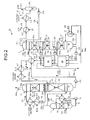
- FIG. 2 is a schematic diagram of the heat recovery system of a CO 2 recovery unit according to the first embodiment.
- FIG. 3 is a chart of a pattern of the heat recovery system of a CO 2 recovery unit according to the first embodiment.
- FIG. 4 is a schematic diagram of an effect of the heat recovery system of a CO 2 recovery unit according to the first embodiment.
- a power generation plant 50 mainly includes a boiler 51 that heats water in a sealed vessel by thermal energy acquired by burning fuel to acquire high-temperature and high-pressure superheated steam 100, a steam turbine 52 that acquires rotative power by the superheated steam 100 from the boiler 51, and a power generator 53 that generates power by the rotative power of the steam turbine 52. Furthermore, the power generation plant 50 includes a flue gas desulfurizer 54 that removes sulfur content (including a sulfur compound) contained in flue gas 101 discharged from the boiler 51, and a CO 2 recovery unit 55 that removes CO 2 (carbon dioxide) contained in the flue gas 101 discharged from the boiler 51. That is, the power generation plant 50 generates power by the superheated steam 100 from the boiler 51, and discharges decarbonated flue gas 101a, in which sulfur content and CO 2 discharged from the boiler 51 are removed, from a stack 56.
- a flue gas desulfurizer 54 that removes sulfur content (including a sulfur compound) contained in flue gas 101 discharged
- the boiler 51 is attached with a Ljungström heat exchanger 57.
- the Ljungström heat exchanger 57 performs heat exchange between the flue gas 101 discharged from the boiler 51 and unburned air 102 supplied to the boiler 51.
- the Ljungström heat exchanger 57 improves the thermal efficiency of the boiler 51 by preheating the unburned air 102 supplied to the boiler 51.
- the heat recovery system of the CO 2 recovery unit 55 includes an air preheater 58 that preheats the unburned air 102 before reaching the Ljungström heat exchanger 57 by exhaust heat from the CO 2 recovery unit 55.
- the CO 2 recovery unit 55 includes a cooling column 1 that cools the flue gas 101 discharged from the boiler 51 by cooling water 103, an absorber 2 that brings a lean solution 104a of an absorbent 104, which is an aqueous solution of an amine compound that absorbs CO 2 , into countercurrent contact with the flue gas 101 so that CO 2 in the flue gas 101 is absorbed by the absorbent 104 and discharges the decarbonated flue gas 101a in which CO 2 has been removed, and a regenerator 3 that emits CO 2 from a rich solution 104b of the absorbent 104 having absorbed CO 2 to regenerate it to the lean solution 104a.
- a cooling column 1 that cools the flue gas 101 discharged from the boiler 51 by cooling water 103
- an absorber 2 that brings a lean solution 104a of an absorbent 104, which is an aqueous solution of an amine compound that absorbs CO 2 , into countercurrent contact with the flue gas 101 so that CO 2 in the flue gas 101
- the flue gas 101 containing CO 2 is boosted by a flue gas blower (not shown) and fed into the cooling column 1, and brought into countercurrent contact with the cooling water 103, thereby cooling the flue gas 101.
- the cooling water 103 is accumulated in a lower part of the cooling column 1 and is supplied to an upper part of the cooling column 1 by a humidified cooling-water circulating pump 1a through a cooling water pipe 1b outside of the cooling column 1.
- the cooling water 103 is brought into countercurrent contact with the flue gas 101 moving upward at a position of a packed bed 1d provided in a process leading to the lower part of the cooling column 1, while flowing down from a nozzle 1c provided in the upper part of the cooling column 1.
- a cooler 1e that condenses the cooling water 103 by cooling to acquire condensed water is provided in the cooling water pipe 1b.
- the flue gas 101 cooled in the cooling column 1 is discharged from a top of the cooling column 1 through a flue gas pipe 1f and supplied to the absorber 2.
- the absorber 2 has a CO 2 absorbing unit 21 in a lower half thereof, and a flushing unit 22 in an upper half thereof.
- the CO 2 absorbing unit 21 brings the flue gas 101 supplied from the cooling column 1 into countercurrent contact with the lean solution 104a of the absorbent 104, so that CO 2 in the flue gas 101 is absorbed by the absorbent 104.
- the lean solution 104a of the absorbent 104 is supplied from the regenerator 3, and brought into countercurrent contact with the flue gas 101 moving upward at a position of a packed bed 21b provided in a process leading to the lower part of the absorber 2, while flowing down from a nozzle 21a, to become the rich solution 104b having absorbed CO 2 , and is accumulated at a bottom of the absorber 2.
- the rich solution 104b of the absorbent 104 accumulated at the bottom of the absorber 2 is pumped by a rich-solution discharge pump 21d installed in a rich solution pipe 21c outside of the absorber 2, and supplied to the regenerator 3.
- the rich solution 104b of the absorbent 104 is heat-exchanged with the lean solution 104a of the absorbent 104 being supplied to the absorber 2 through a lean solution pipe 33d described later by a rich-lean heat exchanger 4.
- the flushing unit 22 brings the decarbonated flue gas 101a with CO 2 being removed by the CO 2 absorbing unit 21 into countercurrent contact with wash water 105 to remove the amine compound entrained with the decarbonated flue gas 101a by the wash water 105, and discharges the decarbonated flue gas 101a with the amine compound being removed, to outside of the absorber 2.
- the wash water 105 is brought into countercurrent contact with the decarbonated flue gas 101a moving upward at a position of a packed bed 22b provided in a process going downward, while flowing down from a nozzle 22a, and is accumulated in a water receptor 22c.
- the wash water 105 accumulated in the water receptor 22c is pumped and circulated by a wash-water discharge pump 22e installed in a wash water pipe 22d outside of the absorber 2, cooled by a cooler 22f, and caused to flow down from the nozzle 22a again.
- the absorber 3 recovers CO 2 from the rich solution 104b of the absorbent 104, regenerates it as the lean solution 104a, and accumulates the lean solution 104a at the bottom, thereby emitting CO 2 from the absorbent 104 having absorbed CO 2 .
- the regenerator 3 is divided into three parts, which are an upper part, a middle part, and a lower part. That is, these are an upper regenerating unit 31, a middle regenerating unit 32, and a lower regenerating unit 33.
- the absorbent 104 is supplied from the rich solution pipe 21c of the CO 2 absorbing unit 21 in the absorber 2, to flow down from a nozzle 31a, passes through a packed bed 31b provided in a process going downward, and accumulated in a chimney tray 31c.
- the absorbent 104 accumulated in the chimney tray 31c is supplied to the middle regenerating unit 32, while being pumped to outside of the regenerator 3 by a semi-lean-solution discharge pump 31e installed in a semi-lean-solution extracting pipe 31d.
- the absorbent 104 is supplied from the semi-lean-solution extracting pipe 31d of the upper regenerating unit 31 to flow down from a nozzle 32a, passes through a packed bed 32b provided in a process going downward, and accumulated in a chimney tray 32c.
- the absorbent 104 accumulated in the chimney tray 32c is supplied to the lower regenerating unit 33, while being pumped to outside of the regenerator 3 by a semi-lean-solution discharge pump 32e installed in a semi-lean-solution extracting pipe 32d.
- the absorbent 104 is supplied from the semi-lean-solution extracting pipe 32d of the middle regenerating unit 32 to flow down from a nozzle 33a, passes through a packed bed 33b provided in a process going downward, and accumulated at a bottom 33c of the regenerator 3.
- the absorbent 104 accumulated at the bottom 33c of the regenerator 3 is pumped to outside of the regenerator 3 by a lean-solution discharge pump 33e installed in a lean-solution extracting pipe 33d, heat-exchanged with the rich solution 104b of the absorbent 104 being supplied to the regenerator 3 through the rich solution pipe 21c by the rich-lean heat exchanger 4, and then, supplied to the absorber 2 while being cooled by a cooler 33f.
- a regenerating heater 34 that uses low-pressure steam 106 from the steam turbine 52 as a source of heat is provided outside of the regenerator 3.
- a part of the absorbent 104 accumulated at the bottom 33c of the regenerator 3 is heated by the regenerating heater 34 while being extracted to outside of the regenerator 3 via a heating pipe 34a to become the lean solution 104a, and returned to the bottom 33c of the regenerator 3 and accumulated therein.
- the low-pressure steam 106 supplied to the regenerating heater 34 heats the absorbent 104 while passing through the heating pipe 34a, to become steam drain 106a and discharged via a drain pipe 34b.
- a lean-solution/steam-drain heat recovery unit 35 is provided in the semi-lean-solution extracting pipe 31d of the upper regenerating unit 31.
- the lean-solution/steam-drain heat recovery unit 35 performs heat exchange between the absorbent 104 being supplied to the middle regenerating unit 32 through the semi-lean-solution extracting pipe 31d and the lean solution 104a of the absorbent 104 being supplied to the absorber 2 via the lean solution pipe 33d and the steam drain 106a being discharged via the drain pipe 34b.
- a lean-solution/steam-drain heat recovery unit 36 is provided in the semi-lean-solution extracting pipe 32d of the middle regenerating unit 32.
- the lean-solution/steam-drain heat recovery unit 36 performs heat exchange between the absorbent 104 being supplied to the lower regenerating unit 33 through the semi-lean-solution extracting pipe 32d and the lean solution 104a of the absorbent 104 being supplied to the absorber 2 via the lean solution pipe 33d and the steam drain 106a being discharged via the drain pipe 34b.
- the rich solution 104b of the absorbent 104 to be supplied to the upper regenerating unit 31 flows down from the nozzle 31a, while being heated by heat exchange with the lean solution 104a of the absorbent 104 being supplied to the absorber 2 by the rich-lean heat exchanger 4, in the process of being supplied to the regenerator 3 via the rich solution pipe 21c.
- the rich solution 104b of the absorbent 104 becomes a semi-lean solution 104c with the most part of CO 2 being emitted by an endothermic reaction, while passing through the packed bed 31b in the process going downward, and is accumulated in the chimney tray 31c.
- the semi-lean solution 104c of the absorbent 104 to be supplied to the middle regenerating unit 32 from the upper regenerating unit 31 through the semi-lean-solution extracting pipe 31d flows down from the nozzle 32a, while being heated by heat exchange by the lean-solution/steam-drain heat recovery unit 35 in the process of being supplied to the middle regenerating unit 32 via the semi-lean-solution extracting pipe 31d.
- CO 2 is further emitted from the semi-lean solution 104c of the absorbent 104 by the endothermic reaction, while passing through the packed bed 32b in the process going downward, and the semi-lean solution 104c is accumulated in the chimney tray 32c.
- the semi-lean solution 104c of the absorbent 104 to be supplied to the lower regenerating unit 33 from the middle regenerating unit 32 through the semi-lean-solution extracting pipe 32d flows down from the nozzle 33a, while being heated by heat exchange by the lean-solution/steam-drain heat recovery unit 36 in the process of being supplied to the lower regenerating unit 33 via the semi-lean-solution extracting pipe 32d.
- the semi-lean solution 104c of the absorbent 104 becomes the lean solution 104a with substantially whole CO 2 being emitted by the endothermic reaction, while passing through the packed bed 33b in the process going downward, and is accumulated at the bottom 33c of the regenerator 3.
- the lean solution 104a accumulated at the bottom 33c of the regenerator 3 is heated by the low-pressure steam 106 in the regenerating heater 34.
- CO 2 gas 107 removed from the absorbent 104 in the respective regenerating units 31, 32, and 33 is recovered by a CO 2 recovering unit 37.
- the CO 2 gas 107 removed from the absorbent 104 moves upward in the regenerator 3, and is discharged to outside of the regenerator 3 from a top of the regenerator 3 through a condensed water pipe 37a.
- moisture is condensed by a CO 2 separator 37c and separated from condensed water 108, and the CO 2 gas 107 is guided to a CO 2 processing step (not shown) by a recovered CO 2 discharge pipe 37d.
- the condensed water 108 separated from CO 2 by the CO 2 separator 37c is pumped by a condensed water pump 37e installed in the condensed water pipe 37a and supplied to the regenerator 3, to flow down from a nozzle 37f provided at the top in the regenerator 3.
- the regenerator 3 includes three stages, which are an upper stage, a middle stage, and a lower stage. That is, these are the upper regenerating unit 31, the middle regenerating unit 32, and the lower regenerating unit 33.
- the regenerator 3 can include two stages, which are upper and lower stages. That is, these are the upper regenerating unit 31 and the lower regenerating unit 33.
- the regenerator 3 is not limited to the upper, middle, and lower stages, which are the upper regenerating unit 31, the middle regenerating unit 32, and the lower regenerating unit 33, and can include three or more regenerating units.
- a heat recovery system that effectively uses low-temperature exhaust heat discharged at the time of recovering CO 2 is explained with reference to FIG. 2 .
- a first heat exchanger ex1 is provided between the rich-lean heat exchanger 4 and the cooler 33f.
- the first heat exchanger ex1 performs heat exchange between the lean solution 104a of the absorbent 104 before being cooled by the cooler 31f via the lean solution pipe 33d and a heat medium (for example, water) 109, and circulates the heat medium to which the exhaust heat of the lean solution 104a is transferred.
- a second heat exchanger ex2 is provided between the wash-water discharge pump 22e and the cooler 22f.
- the second heat exchanger ex2 performs heat exchange between the heat medium (for example, water) 109 and the wash water 105 before being cooled by the cooler 22f via the wash water pipe 22d, and circulates the heat medium to which the exhaust heat of the wash water 105 is transferred.
- a third heat exchanger ex3 is provided between the regenerator 3 and the regenerator reflux condenser 37b.
- the third heat exchanger ex3 performs heat exchange between the CO 2 gas 107 before being cooled by the regenerator reflux condenser 37b via the condensed water pipe 37a and the heat medium 109 in the first heat exchanger ex1 or the second heat exchanger ex2 and circulates the heat medium 109, while transferring the exhaust heat of the CO 2 gas 107 to the heat medium 109.
- All or at least one of the heat medium 109 heat-exchanged by these heat exchangers ex1, ex2, and ex3 is circulated from [a] to [b] of the CO 2 recovery unit 55 so as to pass through the air preheater 58 of the power generation plant 50 shown in FIG. 1 , and used for preheating the unburned air 102 before reaching the Ljungström heat exchanger 57.
- a pattern 1 shown in FIG. 3 uses the heat medium 109 circulated only to the first heat exchanger ex1, in which the heat medium 109 at a temperature of 44.3°C heat-transferred by the first heat exchanger ex1 is supplied from [a-1] (corresponding to [a] shown in FIG. 1 ) to the air preheater 58.
- the heat medium 109 at a temperature of 33.1°C heat-exchanged via the air preheater 58 is returned to [b-1] (corresponding to [b] in FIG. 1 ) and heat-transferred again through the first heat exchanger ex1.
- a pattern 2 shown in FIG. 3 uses the heat medium 109 circulated only to the second heat exchanger ex2, in which the heat medium 109 at a temperature of 47°C heat-transferred by the second heat exchanger ex2 is supplied from [a-2] (corresponding to [a] shown in FIG. 1 ) to the air preheater 58.
- the heat medium 109 at a temperature of 33.1°C heat-exchanged via the air preheater 58 is returned to [b-2] (corresponding to [b] in FIG. 1 ) and heat-transferred again through the second heat exchanger ex2.
- a pattern 3 shown in FIG. 3 uses the heat medium 109 circulated to the first heat exchanger ex1 and the second heat exchanger ex2, in which the heat medium 109 at a temperature of 44.3°C heat-transferred by the first heat exchanger ex1 is supplied from [a-1] to [b-2], and then the heat medium 109 at a temperature of 47°C heat-transferred by the second heat exchanger ex2 is supplied from [a-2] (corresponding to [a] shown in FIG. 1 ) to the air preheater 58.
- the heat medium 109 at a temperature of 33.1°C heat-exchanged via the air preheater 58 is returned to [b-1] (corresponding to [b] in FIG. 1 ) and heat-transferred again through the first heat exchanger ex1 and the second heat exchanger ex2.
- a pattern 4 shown in FIG. 3 uses the heat medium 109 circulated to the first heat exchanger ex1 and the third heat exchanger ex3, in which the heat medium 109 at a temperature of 44.3°C heat-transferred by the first heat exchanger ex1 is supplied from [a-1] to [x] (corresponding to [a] in FIG. 1 ), and then the heat medium 109 at a temperature of 78.6°C heat-transferred by the third heat exchanger ex3 is supplied from [a-3] to the air preheater 58.
- the heat medium 109 at a temperature of 33.4°C heat-exchanged via the air preheater 58 is returned to [b-1] (corresponding to [b] in FIG. 1 ) and heat-transferred again through the first heat exchanger ex1 and the third heat exchanger ex3.
- a pattern 5 shown in FIG. 3 uses the heat medium 109 circulated to the second heat exchanger ex2 and the third heat exchanger ex3, in which the heat medium 109 at a temperature of 47°C heat-transferred by the second heat exchanger ex2 is supplied from [a-2] to [x], and then the heat medium 109 at a temperature of 79.2°C heat-transferred by the third heat exchanger ex3 is supplied from [a-3] (corresponding to [a] in FIG. 1 ) to the air preheater 58.
- the heat medium 109 at a temperature of 33.4°C heat-exchanged via the air preheater 58 is returned to [b-2] (corresponding to [b] in FIG. 1 ) and heat-transferred again through the second heat exchanger ex2 and the third heat exchanger ex3.
- a pattern 6 shown in FIG. 3 uses the heat medium 109 circulated to the first heat exchanger ex1, the second heat exchanger ex2, and the third heat exchanger ex3, in which the heat medium 109 at a temperature of 44.3°C heat-transferred by the first heat exchanger ex1 is supplied from [a-1] to [b-2], the heat medium 109 at a temperature of 47°C heat-transferred by the second heat exchanger ex2 is supplied from [a-2] to [x], and then the heat medium 109 at a temperature of 79.3°C heat-transferred by the third heat exchanger ex3 is supplied from [a-3] (corresponding to [a] in FIG. 1 ) to the air preheater 58.
- the heat medium 109 at a temperature of 33°C heat-exchanged via the air preheater 58 is returned to [b-1] (corresponding to [b] in FIG. 1 ) and heat-transferred again through the first heat exchanger ex1, the second heat exchanger ex2, and the third heat exchanger ex3.
- the gas temperature of the heat-exchanged unburned air 102 at the position C in the upstream of the boiler 51 via the Ljungström heat exchanger 57 became 294°C. Furthermore, the gas temperature of the flue gas 101 at the position D in the upstream of the Ljungström heat exchanger 57 via the boiler 51 became 350°C. Furthermore, the gas temperature of the heat-exchanged flue gas 101 at the position E in the upstream of the flue gas desulfurizer 54 via the Ljungström heat exchanger 57 became 130°C. At this time, the flow rate G of the low-pressure steam 106 supplied to the regenerating heater 34 of the CO 2 recovery unit 55 was 870 t/hr.
- the air preheater 58 that preheats the unburned air 102 before reaching the Ljungström heat exchanger 57 by exhaust heat from the CO 2 recovery unit 55 is provided.
- low-temperature exhaust heat equal to or lower than a temperature level of 70°C to 80°C discharged at the time of recovering CO 2 can be used efficiently.
- a gas temperature of 294°C of the unburned air 102 at the position C supplied to the boiler 51 in the conventional case is raised by 28°C to be 322°C.
- a heat input to the boiler 51 increases due to the increase of 28°C, and effects equivalent to those of decreasing the flow rate of the low-pressure steam 106 consumed by the CO 2 recovery unit 55 by 56 t/hr can be acquired.
- the flow rate of 56 t/hr corresponds to 6% of the flow rate of the low-pressure steam 106 consumed by the CO 2 recovery unit 55.
- the Ljungström heat exchanger 57 performs heat exchange between the flue gas 101 containing sulfur content and the unburned air 102, the heat reservoir may be subjected to sulfuric acid corrosion due to dew condensation generated on the heat transfer surface of the heat reservoir.
- the gas temperature of 30°C of the unburned air 102 at the position B on an inlet side of the Ljungström heat exchanger 57 in the conventional case is raised to 72°C
- the gas temperature of 130°C of the flue gas 101 at the position E on an outlet side of the Ljungström heat exchanger 57 in the conventional case is also raised to 141°C.
- an average cold-end temperature ((the gas temperature on the outlet side of flue gas + the gas temperature on the inlet side of unburned air)/2) of the Ljungström heat exchanger 57 increases from 80°C to 106.5°C by 26.5°C. Consequently, dew condensation on the heat transfer surface of the heat reservoir of the Ljungström heat exchanger 57 can be prevented and sulfuric acid corrosion of the heat reservoir can be suppressed.
- the heat recovery system of the CO 2 recovery unit 55 according to the first embodiment is applied to the power generation plant 50 that drives the steam turbine 52 by the superheated steam 100 from the boiler 51 to generate power by the power generator 53.
- the gas temperature of 294°C of the unburned air 102 at the position C supplied to the boiler 51 in the conventional case is raised by 28°C to be 322°C. Therefore, because the flow rate of the superheated steam 100 supplied from the boiler 51 to the steam turbine 52 increases, the power generation efficiency of the power generation plant 50 can be improved.
- the air preheater 58 circulates the heat medium 109, to which exhaust heat from the CO 2 recovery unit 55 is heat-transferred, to heat the unburned air 102 indirectly.
- a exhaust heat fluid such as the absorbent 104, the wash water 105, or the CO 2 gas 107 can be prevented from flowing out, with respect to a case where the exhaust heat fluid is used to heat the unburned air 102 directly.
- a heat recovery method of the CO 2 recovery unit 55 includes a step of removing CO 2 in the flue gas 101 discharged from the boiler 51 by absorbing CO 2 by the absorbent 104, emitting CO 2 from the absorbent 104 having absorbed CO 2 , and of reusing the absorbent 104 for absorbing CO 2 (CO 2 recovery step).
- the heat recovery method further includes a step of performing heat exchange between the flue gas 101 discharged from the boiler 51 and before reaching the CO 2 recovery step and the unburned air 102 supplied to the boiler 51 (heat exchanging step), and a step of preheating the unburned air 102 before reaching the heat exchanging step by exhaust heat from the CO 2 recovery step (air preheating step).
- low-temperature exhaust heat equal to or lower than a temperature level of 70°C to 80°C discharged at the time of recovering CO 2 can be used efficiently.
- the gas temperature of 294°C of the unburned air 102 at the position C supplied to the boiler 51 in the conventional case is raised by 28°C to be 322°C.
- a heat input to the boiler 51 increases due to the increase of 28°C, and effects equivalent to those of decreasing the flow rate of the low-pressure steam 106 consumed by the CO 2 recovery unit 55 by 56 t/hr can be acquired.
- the flow rate of 56 t/hr corresponds to 6% of the flow rate of the low-pressure steam 106 consumed by the CO 2 recovery unit 55.
- the heat reservoir may be subjected to sulfuric acid corrosion due to dew condensation generated on the heat transfer surface of the heat reservoir.
- the gas temperature of 30°C of the unburned air 102 at the position B on the inlet side of the heat exchanging step in the conventional case is raised to 72°C
- the gas temperature of 130°C of the flue gas 101 at the position E on the outlet side of the heat exchanging step in the conventional case is also raised to 141°C.
- an average cold-end temperature ((the gas temperature on the outlet side of flue gas + the gas temperature on the inlet side of unburned air)/2) at the heat exchanging step increases from 80°C to 106.5°C by 26.5°C. Consequently, dew condensation on the heat transfer surface of the heat reservoir at the heat exchanging step can be prevented and sulfuric acid corrosion of the heat reservoir can be suppressed.
- the heat recovery method of the CO 2 recovery unit 55 according to the first embodiment further includes a power generation step of driving the steam turbine 52 by the superheated steam 100 from the boiler 51 to generate power by the power generator 53.
- the gas temperature of 294°C of the unburned air 102 at the position C supplied to the boiler 51 in the conventional case is raised by 28°C to be 322°C. Therefore, because the flow rate of the superheated steam 100 supplied from the boiler 51 to the steam turbine 52 increases, the power generation efficiency of the power generation plant 50 can be improved.
- FIG. 5 is a schematic diagram of a heat recovery system of a CO 2 recovery unit according to the second embodiment.
- FIG. 6 is a chart of a pattern of the heat recovery system of a CO 2 recovery unit according to the second embodiment.
- FIG. 7 is a schematic diagram of an effect of the heat recovery system of a CO 2 recovery unit according to the second embodiment.
- the heat recovery system of the CO 2 recovery unit 55 includes the air preheater 58 that preheats the unburned air 102 before reaching the Ljungström heat exchanger 57 by exhaust heat from the CO 2 recovery unit 55, but the mode of exhaust heat in the CO 2 recovery unit 55 is different from that of the first embodiment. Therefore, in the second embodiment, exhaust heat from the CO 2 recovery unit 55 is explained, and elements equivalent to those in the first embodiment described above are denoted by like reference signs and explanations thereof will be omitted.
- the heat recovery system that efficiently uses low-temperature exhaust heat discharged at the time of recovering CO 2 in the CO 2 recovery unit 55 is explained with reference to FIG. 5 .
- the lean solution pipe 33d for supplying the lean solution 104a of the absorbent 104 from the regenerator 3 to the absorber 2 is provided between the rich-lean heat exchanger 4 and the cooler 33f via the air preheater 58.
- the wash water pipe 22d in the flushing unit 22 of the absorber 2 is provided between the wash-water discharge pump 22e and the cooler 22f via the air preheater 58.
- the condensed water pipe 37a in the CO 2 recovering unit 37 is provided between the regenerator 3 and the regenerator reflux condenser 37b via the air preheater 58.
- All of the lean solution 104a of the absorbent 104 passing through the lean solution pipe 33d, the wash water 105 passing through the wash water pipe 22d, and the CO 2 gas 107 passing through the condensed water pipe 37a or at least one of these exhaust heat fluids is circulated from [a] to [b] of the CO 2 recovery unit 55 through the air preheater 58 shown in FIG. 1 of the power generation plant 50 and used for preheating the unburned air 102 before reaching the Ljungström heat exchanger 57.
- the lean solution 104a of the absorbent 104 at a temperature of 47.3°C heat-exchanged by the rich-lean heat exchanger 4 is supplied from [a-1'] (corresponding to [a] shown in FIG. 1 ) to the air preheater 58.
- the lean solution 104a at a temperature of 44.9°C heat-exchanged via the air preheater 58 is returned to [b-1'] (corresponding to [b] shown in FIG. 1 ), cooled by the cooler 33f, and used for absorbing CO 2 .
- the wash water 105 at a temperature of 50°C heat-exchanged with the decarbonated flue gas 101a is supplied from [a-2'] (corresponding to [a] shown in FIG. 1 ) to the air preheater 58.
- the wash water 105 at a temperature of 48.5°C heat-exchanged via the air preheater 58 is returned to [b-2'] (corresponding to [b] shown in FIG. 1 ), cooled by the cooler 22f, and used for cleaning of the decarbonated flue gas 101a.
- the CO 2 gas 107 at a temperature of 85.9°C which has been removed from the rich solution 104b of the absorbent 104 by the endothermic reaction, is supplied from [a-3'] (corresponding to [a] shown in FIG. 1 ) to the air preheater 58.
- the CO 2 gas 107 at a temperature of 75.5°C heat-exchanged via the air preheater 58 is returned to [b-3'] (corresponding to [b] shown in FIG. 1 ), cooled by the regenerator reflux condenser 37b, and recovered.
- a pattern 4 shown in FIG. 6 uses the pattern 1 and the pattern 2 in parallel, in which the lean solution 104a of the absorbent 104 at a temperature of 47.3°C is supplied from [a-1'] (corresponding to [a] shown in FIG. 1 ) to the air preheater 58, and the wash water 105 at a temperature of 50°C is supplied from [a-2'] (corresponding to [a] shown in FIG. 1 ) to the air preheater 58.
- the lean solution 104a at a temperature of 44.9°C heat-exchanged via the air preheater 58 is returned to [b-1'] (corresponding to [b] shown in FIG. 1 ), and the wash water 105 at a temperature of 49.6°C heat-exchanged via the air preheater 58 is returned to [b-2'] (corresponding to [b] shown in FIG. 1 .
- a pattern 5 shown in FIG. 6 uses the pattern 1 and the pattern 3 in parallel, in which the lean solution 104a of the absorbent 104 at a temperature of 47.3°C is supplied from [a-1'] (corresponding to [a] shown in FIG. 1 ) to the air preheater 58, and the CO 2 gas 107 at a temperature of 85.9°C is supplied from [a-3'] (corresponding to [a] shown in FIG. 1 ) to the air preheater 58.
- the lean solution 104a at a temperature of 44.9°C heat-exchanged via the air preheater 58 is returned to [b-1'] (corresponding to [b] shown in FIG. 1 ), and the CO 2 gas 107 at a temperature of 78.9°C heat-exchanged via the air preheater 58 is returned to [b-3'] (corresponding to [b] shown in FIG. 1 ).
- a pattern 6 shown in FIG. 6 uses the pattern 2 and the pattern 3 in parallel, in which the wash water 105 at a temperature of 50°C is supplied from [a-2'] (corresponding to [a] shown in FIG. 1 ) to the air preheater 58, and the CO 2 gas 107 at a temperature of 85.9°C is supplied from [a-3'] (corresponding to [a] shown in FIG. 1 ) to the air preheater 58.
- the wash water 105 at a temperature of 48.5°C heat-exchanged via the air preheater 58 is returned to [b-2'] (corresponding to [b] shown in FIG. 1 ), and the CO 2 gas 107 at a temperature of 79.6°C heat-exchanged via the air preheater 58 is returned to [b-3'] (corresponding to [b] shown in FIG. 1 ).
- a pattern 7 shown in FIG. 6 uses the pattern 1, the pattern 2 and the pattern 3 in parallel, in which the lean solution 104a of the absorbent 104 at a temperature of 47.3°C is supplied from [a-1'] (corresponding to [a] shown in FIG. 1 ) to the air preheater 58, the wash water 105 at a temperature of 50°C is supplied from [a-2'] (corresponding to [a] shown in FIG. 1 ) to the air preheater 58, and the CO 2 gas 107 at a temperature of 85.9°C is supplied from [a-3'] (corresponding to [a] shown in FIG. 1 ) to the air preheater 58.
- the lean solution 104a at a temperature of 44.9°C heat-exchanged via the air preheater 58 is returned to [b-1'] (corresponding to [b] shown in FIG. 1 )
- the wash water 105 at a temperature of 49.6°C heat-exchanged via the air preheater 58 is returned to [b-2'] (corresponding to [b] shown in FIG. 1 )
- the CO 2 gas 107 at a temperature of 79.8°C heat-exchanged via the air preheater 58 is returned to [b-3'] (corresponding to [b] shown in FIG. 1 ).
- the gas temperature of the heat-exchanged unburned air 102 at the position C in the upstream of the boiler 51 via the Ljungström heat exchanger 57 became 294°C. Furthermore, the gas temperature of the flue gas 101 at the position D in the upstream of the Ljungström heat exchanger 57 via the boiler 51 became 350°C. Further, the gas temperature of the heat-exchanged flue gas 101 at the position E in the upstream of the flue gas desulfurizer 54 via the Ljungström heat exchanger 57 became 130°C. At this time, the flow rate G of the low-pressure steam 106 supplied to the regenerating heater 34 of the CO 2 recovery unit 55 was 870 t/hr.
- the air preheater 58 that preheats the unburned air 102 before reaching the Ljungström heat exchanger 57 by exhaust heat from the CO 2 recovery unit 55 is provided.
- low-temperature exhaust heat equal to or lower than a temperature level of 70°C to 80°C discharged at the time of recovering CO 2 can be used efficiently.
- the gas temperature of 294°C of the unburned air 102 at the position C supplied to the boiler 51 in the conventional case is raised by 29°C to be 323°C.
- a heat input to the boiler 51 increases due to the increase of 29°C, and effects equivalent to those of decreasing the flow rate of the low-pressure steam 106 consumed by the CO 2 recovery unit 55 by 58 t/hr can be acquired.
- the flow rate of 58 t/hr corresponds to 7% of the flow rate of the low-pressure steam 106 consumed by the CO 2 recovery unit 55.
- the Ljungström heat exchanger 57 performs heat exchange between the flue gas 101 containing sulfur content and the unburned air 102, the heat reservoir may be subjected to sulfuric acid corrosion due to dew condensation generated on the heat transfer surface of the heat reservoir.
- the gas temperature of 30°C of the unburned air 102 at the position B on the inlet side of the Ljungström heat exchanger 57 in the conventional case is raised to 82°C, and the gas temperature of 130°C of the flue gas 101 at the position E on the outlet side of the Ljungström heat exchanger 57 in the conventional case is also raised to 148°C.
- an average cold-end temperature ((the gas temperature on the outlet side of flue gas + the gas temperature on the inlet side of unburned air)/2) of the Ljungström heat exchanger 57 increases from 80°C to 115°C by 35°C. Consequently, dew condensation on the heat transfer surface of the heat reservoir of the Ljungström heat exchanger 57 can be prevented and sulfuric acid corrosion of the heat reservoir can be suppressed.
- the heat recovery system of the CO 2 recovery unit 55 according to the second embodiment is applied to the power generation plant 50 that drives the steam turbine 52 by the superheated steam 100 from the boiler 51 to generate power by the power generator 53.
- the gas temperature of 294°C of the unburned air 102 at the position C supplied to the boiler 51 in the conventional case is raised by 29°C to be 323°C. Therefore, because the flow rate of the superheated steam 100 supplied from the boiler 51 to the steam turbine 52 increases, the power generation efficiency of the power generation plant 50 can be improved.
- the air preheater 58 circulates all or at least one of the respective exhaust heat fluids (the lean solution 104a of the absorbent 104, the wash water 105, and the CO 2 gas 107) from the CO 2 recovery unit 55, thereby directly heating the unburned air 102.
- the heat transfer efficiency can be improved with respect to the case where the unburned air 102 is indirectly heated via the heat medium.
- a heat recovery method of the CO 2 recovery unit 55 includes a step of removing CO 2 in the flue gas 101 discharged from the boiler 51 by absorbing CO 2 by the absorbent 104, emitting CO 2 from the absorbent 104 having absorbed CO 2 , and of reusing the absorbent 104 for absorbing CO 2 (CO 2 recovery step).
- the heat recovery method further includes a step of performing heat exchange between the flue gas 101 discharged from the boiler 51 and before reaching the CO 2 recovery step and the unburned air 102 supplied to the boiler 51 (heat exchanging step), and a step of preheating the unburned air 102 before reaching the heat exchanging step by exhaust heat from the CO 2 recovery step (air preheating step).
- low-temperature exhaust heat equal to or lower than the temperature level of 70°C to 80°C discharged at the time of recovering CO 2 can be used efficiently.
- the gas temperature of 294°C of the unburned air 102 at the position C supplied to the boiler 51 in the conventional case is raised by 29°C to be 323°C.
- a heat input to the boiler 51 increases due to the increase of 29°C, and effects equivalent to those of decreasing the flow rate of the low-pressure steam 106 consumed at the CO 2 recovery step by 58 t/hr can be acquired.
- the flow rate of 58 t/hr corresponds to 7% of the flow rate of the low-pressure steam 106 consumed at the CO 2 recovery step.
- the heat reservoir may be subjected to sulfuric acid corrosion due to dew condensation generated on the heat transfer surface of the heat reservoir.
- the gas temperature of 30°C of the unburned air 102 at the position B on the inlet side of the heat exchanging step in the conventional case is raised to 82°C
- the gas temperature of 130°C of the flue gas 101 at the position E on the outlet side of the heat exchanging step in the conventional case is also raised to 148°C.
- an average cold-end temperature ((the gas temperature on the outlet side of flue gas + the gas temperature on the inlet side of unburned air)/2) at the heat exchanging step is increased from 80°C to 115°C by 35°C. Consequently, dew condensation on the heat transfer surface of the heat reservoir at the heat exchanging step can be prevented and sulfuric acid corrosion of the heat reservoir can be suppressed.
- the heat recovery method of the CO 2 recovery unit 55 according to the second embodiment further includes a step of driving the steam turbine 52 by the superheated steam 100 from the boiler 51 to generate power by the power generator 53 (power generation step).
- the gas temperature of 294°C of the unburned air 102 at the position C supplied to the boiler 51 in the conventional case is raised by 29°C to be 323°C. Therefore, because the flow rate of the superheated steam 100 supplied from the boiler 51 to the steam turbine 52 increases, the power generation efficiency of the power generation plant 50 can be improved.
- FIG. 8 is a schematic diagram of a power generation plant to which a heat recovery system of a CO 2 recovery unit according to the third embodiment is applied.
- FIG. 9 is a schematic diagram of the heat recovery system of a CO 2 recovery unit according to the third embodiment.
- FIG. 10 is a chart of a pattern of the heat recovery system of a CO 2 recovery unit according to the third embodiment.
- FIG. 11 is a schematic diagram of an effect of the heat recovery system of a CO 2 recovery unit according to the third embodiment.
- the heat recovery system of the CO 2 recovery unit 55 includes, as shown in FIG. 8 , a heat recovery device 59 that recovers the heat of the flue gas 101 before reaching the CO 2 recovery unit 55 via the Ljungström heat exchanger 57 and supplies the heat to the CO 2 recovery unit 55 in addition to the heat recovery system of the first embodiment. Therefore, in the third embodiment, heat recovery from the heat recovery device 59 to the CO 2 recovery unit 55 is explained, and elements equivalent to those in the first embodiment described above are denoted by like reference signs and explanations thereof will be omitted.
- the rich solution pipe 21c for supplying the rich solution 104b of the absorbent 104 from the absorber 2 to the regenerator 3 is provided between the rich-lean heat exchanger 4 and the nozzle 31a of the regenerator 3 via the heat recovery device 59.
- the semi-lean-solution extracting pipe 31d in the regenerator 3 is provided between the lean-solution/steam-drain heat recovery unit 35 and the nozzle 32a via the heat recovery device 59.
- the semi-lean-solution extracting pipe 32d in the regenerator 3 is provided between the lean-solution/steam-drain heat recovery unit 36 and the nozzle 33a via the heat recovery device 59.
- All or at least one of the exhaust heat fluids of the rich solution 104b of the absorbent 104 passing through the rich solution pipe 21c, the semi-lean solution 104c passing through the semi-lean-solution extracting pipe 31d, and the semi-lean solution 104c passing through the semi-lean-solution extracting pipe 32d is circulated from [c] to [d] of the CO 2 recovery unit 55 via the heat recovery device 59 of the power generation plant 50 shown in FIG. 8 , and used for recovering the heat of the flue gas 101 before reaching the CO 2 recovery unit 55 via the Ljungström heat exchanger 57.
- the rich solution 104b of the absorbent 104 at a temperature of 91.2°C heat-exchanged by the rich-lean heat exchanger 4 is supplied from [c-1] (corresponding to [c] shown in FIG. 8 ) to the heat recovery device 59.
- the rich solution 104b at a temperature of 100.8°C heat-recovered via the heat recovery device 59 is returned to [d-1] (corresponding to [d] shown in FIG. 8 ), caused to flow down from the nozzle 31a into the regenerator 3, thereby reacting endothermically.
- the semi-lean solution 104c of the absorbent 104 at a temperature of 105.0°C heat-recovered by the lean-solution/steam-drain heat recovery unit 35 is supplied from [c-2] (corresponding to [c] shown in FIG. 8 ) to the heat recovery device 59.
- the semi-lean solution 104c at a temperature of 112.4°C heat-recovered via the heat recovery device 59 is returned to [d-2] (corresponding to [d] shown in FIG. 8 ), caused to flow down from the nozzle 32a into the regenerator 3, thereby reacting endothermically.
- the semi-lean solution 104c of the absorbent 104 at a temperature of 117.6°C heat-recovered by the lean-solution/steam-drain heat recovery unit 36 is supplied from [c-3] (corresponding to [c] shown in FIG. 8 ) to the heat recovery device 59.
- the semi-lean solution 104c at a temperature of 123.2°C heat-recovered via the heat recovery device 59 is returned to [d-3] (corresponding to [d] shown in FIG. 8 ), caused to flow down from the nozzle 33a into the regenerator 3, thereby reacting endothermically.
- a pattern 4 shown in FIG. 10 uses the pattern 1 and the pattern 2 in parallel, in which the rich solution 104b of the absorbent 104 at a temperature of 91.2°C is supplied from [c-1] (corresponding to [c] shown in FIG. 8 ) to the heat recovery device 59, and the semi-lean solution 104c of the absorbent 104 at a temperature of 105.0°C is supplied from [c-2] (corresponding to [c] shown in FIG. 8 ) to the heat recovery device 59.
- the rich solution 104b at a temperature of 94.1°C heat-recovered via the heat recovery device 59 is returned to [d-1] (corresponding to [d] shown in FIG. 8 ), and the semi-lean solution 104c at a temperature of 112.4°C heat-recovered via the heat recovery device 59 is returned to [d-2] (corresponding to [d] shown in FIG. 8 ).
- a pattern 5 shown in FIG. 10 uses the pattern 1 and the pattern 3 in parallel, in which the rich solution 104b of the absorbent 104 at a temperature of 91.2°C is supplied from [c-1] (corresponding to [c] shown in FIG. 8 ) to the heat recovery device 59, and the semi-lean solution 104c of the absorbent 104 at a temperature of 117.6°C is supplied from [c-3] (corresponding to [c] shown in FIG. 8 ) to the heat recovery device 59.
- the rich solution 104b at a temperature of 95.6°C heat-recovered via the heat recovery device 59 is returned to [d-1] (corresponding to [d] shown in FIG. 8 ), and the semi-lean solution 104c at a temperature of 123.2°C heat-recovered via the heat recovery device 59 is returned to [d-3] (corresponding to [d] shown in FIG. 8 ).
- a pattern 6 shown in FIG. 10 uses the pattern 2 and the pattern 3 in parallel, in which the semi-lean solution 104c of the absorbent 104 at a temperature of 105.0°C is supplied from [c-2] (corresponding to [c] shown in FIG. 8 ) to the heat recovery device 59, and the semi-lean solution 104c of the absorbent 104 at a temperature of 117.6°C is supplied from [c-3] (corresponding to [c] shown in FIG. 8 ) to the heat recovery device 59.
- the semi-lean solution 104c at a temperature of 107.4°C heat-recovered via the heat recovery device 59 is returned to [d-2] (corresponding to [d] shown in FIG. 8 ), and the semi-lean solution 104c at a temperature of 123.2°C heat-recovered via the heat recovery device 59 is returned to [d-3] (corresponding to [d] shown in FIG. 8 ).
- a pattern 7 shown in FIG. 10 uses the pattern 1, the pattern 2 and the pattern 3 in parallel, in which the rich solution 104b of the absorbent 104 at a temperature of 91.2°C is supplied from [c-1] (corresponding to [c] shown in FIG. 8 ) to the heat recovery device 59, the semi-lean solution 104c of the absorbent 104 at a temperature of 105.0°C is supplied from [c-2] (corresponding to [c] shown in FIG. 8 ) to the heat recovery device 59, and the semi-lean solution 104c of the absorbent 104 at a temperature of 117.6°C is supplied from [c-3] (corresponding to [c] shown in FIG. 8 ) to the heat recovery device 59.
- the rich solution 104b at a temperature of 93.4°C heat-recovered via the heat recovery device 59 is returned to [d-1] (corresponding to [d] shown in FIG. 8 )
- the semi-lean solution 104c at a temperature of 107.4°C heat-recovered via the heat recovery device 59 is returned to [d-2] (corresponding to [d] shown in FIG. 8 )
- the semi-lean solution 104c at a temperature of 123.2°C heat-recovered via the heat recovery device 59 is returned to [d-3] (corresponding to [d] shown in FIG. 8 ).
- the gas temperature of the heat-exchanged unburned air 102 at the position C in the upstream of the boiler 51 via the Ljungström heat exchanger 57 became 302°C. Furthermore, the gas temperature of the flue gas 101 at the position D in the upstream of the Ljungström heat exchanger 57 via the boiler 51 became 350°C. Further, the gas temperature of the heat-exchanged flue gas 101 at the position E in the upstream of the heat recovery device 59 via the Ljungström heat exchanger 57 became 158°C. Further, the gas temperature of the heat-recovered flue gas 101 at a position F in the upstream of the flue gas desulfurizer 54 via the heat recovery device 59 became 104°C. At this time, the flow rate G of the low-pressure steam 106 supplied to the regenerating heater 34 of the CO 2 recovery unit 55 was 800 t/hr.
- the gas temperature of the flue gas 101 at the position D in the upstream of the Ljungström heat exchanger 57 via the boiler 51 became 350°C. Furthermore, the gas temperature of the heat-exchanged flue gas 101 at the position E in the upstream of the flue gas desulfurizer 54 via the Ljungström heat exchanger 57 became 130°C. Because the heat recovery device 59 is not provided, the gas temperature of the flue gas 101 corresponding to the position F is 130°C. At this time, the flow rate G of the low-pressure steam 106 supplied to the regenerating heater 34 of the CO 2 recovery unit 55 was 870 t/hr.
- the heat recovery device 59 that recovers the heat of the flue gas 101 before reaching the CO 2 recovery unit 55 via the Ljungström heat exchanger 57 and supplies the heat to the CO 2 recovery unit 55 is further provided, with respect to the heat recovery system of the first embodiment.
- recovered heat can be effectively used, while effectively using low-temperature exhaust heat equal to or lower than a temperature level of 70°C to 80°C discharged at the time of recovering CO 2 .
- the gas temperature of 294°C of the unburned air 102 at the position C supplied to the boiler 51 in the conventional case is raised by 8°C to be 302°C.
- a heat input to the boiler 51 increases due to the increase of 8°C, and effects equivalent to those of decreasing the flow rate of the low-pressure steam 106 consumed by the CO 2 recovery unit 55 by 15 t/hr can be acquired.
- the flow rate of 15 t/hr corresponds to 1.7% of the flow rate of the low-pressure steam 106 consumed by the CO 2 recovery unit 55. Furthermore, the flow rate of 870 t/hr of the low-pressure steam 106 supplied to the regenerating heater 34 of the CO 2 recovery unit 55 in the conventional case is decreased to 800 t/hr by 70 t/hr. The flow rate of 70 t/hr corresponds to 8% of the flow rate of the low-pressure steam 106 consumed by the CO 2 recovery unit 55. That is, the flow rate of the low-pressure steam 106 consumed by the CO 2 recovery unit 55 is decreased by 9.7% in total.
- the flow rate of the low-pressure steam 106 consumed by the CO 2 recovery unit 55 can be decreased.
- the Ljungström heat exchanger 57 performs heat exchange between the flue gas 101 containing sulfur content and the unburned air 102, the heat reservoir may be subjected to sulfuric acid corrosion due to dew condensation generated on the heat transfer surface of the heat reservoir.
- the gas temperature of 30°C of the unburned air 102 at the position B on the inlet side of the Ljungström heat exchanger 57 in the conventional case is raised to 72°C
- the gas temperature of 130°C of the flue gas 101 at the position E on the outlet side of the Ljungström heat exchanger 57 in the conventional case is also raised to 158°C.
- an average cold-end temperature ((the gas temperature on the outlet side of flue gas + the gas temperature on the inlet side of unburned air)/2) of the Ljungström heat exchanger 57 increases from 80°C to 115°C by 35°C. Consequently, dew condensation on the heat transfer surface of the heat reservoir of the Ljungström heat exchanger 57 can be prevented and sulfuric acid corrosion of the heat reservoir can be suppressed.
- the heat recovery system of the CO 2 recovery unit 55 according to the third embodiment is applied to the power generation plant 50 that drives the steam turbine 52 by the superheated steam 100 from the boiler 51 to generate power by the power generator 53.
- the gas temperature of 294°C of the unburned air 102 at the position C supplied to the boiler 51 in the conventional case is raised by 8°C to be 302°C. Therefore, because the flow rate of the superheated steam 100 supplied from the boiler 51 to the steam turbine 52 increases, the power generation efficiency of the power generation plant 50 can be improved.
- a heat recovery method of the CO 2 recovery unit 55 according to the third embodiment further includes a step of recovering the heat of the flue gas 101 before reaching the CO 2 recovery step through the heat exchanging step, and of supplying the heat to the CO 2 recovery step (heat recovery step), with respect to the heat recovery method of the first embodiment.
- low-temperature exhaust heat equal to or lower than the temperature level of 70°C to 80°C discharged at the time of recovering CO 2 can be used efficiently.
- the gas temperature of 294°C of the unburned air 102 at the position C supplied to the boiler 51 in the conventional case is raised by 8°C to be 302°C.
- a heat input to the boiler 51 increases due to the increase of 8°C, and effects equivalent to those of decreasing the flow rate of the low-pressure steam 106 consumed at the CO 2 recovery step by 15 t/hr can be acquired.
- the flow rate of 15 t/hr corresponds to 1.7% of the flow rate of the low-pressure steam 106 consumed at the CO 2 recovery step.
- the flow rate of 870 t/hr of the low-pressure steam 106 supplied to the CO 2 recovery step in the conventional case is decreased to 800 t/hr by 70 t/hr.
- the flow rate of 70 t/hr corresponds to 8% of the flow rate of the low-pressure steam 106 consumed at the CO 2 recovery step. That is, the flow rate of the low-pressure steam 106 consumed at the CO 2 recovery step is decreased by 9.7% in total.
- the flow rate of the low-pressure steam 106 consumed at the CO 2 recovery step can be decreased.
- the heat reservoir may be subjected to sulfuric acid corrosion due to dew condensation generated on the heat transfer surface of the heat reservoir.
- the gas temperature of 30°C of the unburned air 102 at the position B on the inlet side of the heat exchanging step in the conventional case is raised to 72°C
- the gas temperature of 130°C of the flue gas 101 at the position E on the outlet side of the heat exchanging step in the conventional case is also raised to 158°C.
- an average cold-end temperature ((the gas temperature on the outlet side of flue gas + the gas temperature on the inlet side of unburned air)/2) at the heat exchanging step is increased from 80°C to 115°C by 35°C. Consequently, dew condensation on the heat transfer surface of the heat reservoir at the heat exchanging step can be prevented and sulfuric acid corrosion of the heat reservoir can be suppressed.
- the heat recovery method of the CO 2 recovery unit 55 according to the third embodiment further includes a power generation step of driving the steam turbine 52 by the superheated steam 100 from the boiler 51 to generate power by the power generator 53.
- the gas temperature of 294°C of the unburned air 102 at the position C supplied to the boiler 51 in the conventional case is raised by 8°C to be 302°C. Therefore, because the flow rate of the superheated steam 100 supplied from the boiler 51 to the steam turbine 52 increases, the power generation efficiency of the power generation plant 50 can be improved.
- the regenerator 3 includes three stages, which are an upper stage, a middle stage, and a lower stage. That is, these are the upper regenerating unit 31, the middle regenerating unit 32, and the lower regenerating unit 33.
- the regenerator 3 can include two stages, which are upper and lower stages. That is, these are the upper regenerating unit 31 and the lower regenerating unit 33.
- the semi-lean-solution extracting pipe 31d in the regenerator 3 is provided between the lean-solution/steam-drain heat recovery unit 35 and the nozzle 32a via the heat recovery device 59, and the pattern 2 and patterns including the pattern 2 shown in FIG. 10 are deleted.
- the regenerator 3 is not limited to the upper, middle, and lower stages, which are the upper regenerating unit 31, the middle regenerating unit 32, and the lower regenerating unit 33, and can include three or more regenerating units. In this case, a pattern for an increased stage and patterns including this pattern are added.
- FIG. 12 is a schematic diagram of a heat recovery system of a CO 2 recovery unit according to the fourth embodiment.
- FIG. 13 is a schematic diagram of an effect of the heat recovery system of a CO 2 recovery unit according to the fourth embodiment.
- the heat recovery system of the CO 2 recovery unit 55 according to the fourth embodiment further includes, as shown in FIGS. 8 and 12 , the heat recovery device 59 that recovers the heat of the flue gas 101 before reaching the CO 2 recovery unit 55 via the Ljungström heat exchanger 57 and supplies the heat to the CO 2 recovery unit 55 in addition to the heat recovery system of the second embodiment. Furthermore, heat recovery from the heat recovery device 59 to the CO 2 recovery unit 55 in the fourth embodiment is identical to that of the third embodiment described above. Therefore, in the fourth embodiment, explanations of heat recovery will be omitted because it has been explained in the second and third embodiments described above.
- the gas temperature of the heat-exchanged unburned air 102 at the position C in the upstream of the boiler 51 via the Ljungström heat exchanger 57 became 303°C. Furthermore, the gas temperature of the flue gas 101 at the position D in the upstream of the Ljungström heat exchanger 57 via the boiler 51 became 350°C. Further, the gas temperature of the heat-exchanged flue gas 101 at the position E in the upstream of the heat recovery device 59 via the Ljungström heat exchanger 57 became 165°C. Further, the gas temperature of the heat-recovered flue gas 101 at the position F in the upstream of the flue gas desulfurizer 54 via the heat recovery device 59 became 104°C. At this time, the flow rate G of the low-pressure steam 106 supplied to the regenerating heater 34 of the CO 2 recovery unit 55 was 791 t/hr.
- the gas temperature of the flue gas 101 at the position D in the upstream of the Ljungström heat exchanger 57 via the boiler 51 became 350°C. Furthermore, the gas temperature of the heat-exchanged flue gas 101 at the position E in the upstream of the flue gas desulfurizer 54 via the Ljungström heat exchanger 57 became 130°C. Because the heat recovery device 59 is not provided, the gas temperature of the flue gas 101 corresponding to the position F is 130°C. At this time, the flow rate G of the low-pressure steam 106 supplied to the regenerating heater 34 of the CO 2 recovery unit 55 was 870 t/hr.
- the heat recovery device 59 that recovers the heat of the flue gas 101 before reaching the CO 2 recovery unit 55 via the Ljungström heat exchanger 57 and supplies the heat to the CO 2 recovery unit 55 is further provided, with respect to the heat recovery system of the second embodiment.
- recovered heat can be effectively used, while effectively using low-temperature exhaust heat equal to or lower than a temperature level of 70°C to 80°C discharged at the time of recovering CO 2 .
- the gas temperature of 294°C of the unburned air 102 at the position C supplied to the boiler 51 in the conventional case is raised by 9°C to be 303°C.
- a heat input to the boiler 51 increases due to the increase of 9°C, and effects equivalent to those of decreasing the flow rate of the low-pressure steam 106 consumed by the CO 2 recovery unit 55 by 17 t/hr can be acquired.
- the flow rate of 17 t/hr corresponds to 2% of the flow rate of the low-pressure steam 106 consumed by the CO 2 recovery unit 55. Furthermore, the flow rate of 870 t/hr of the low-pressure steam 106 supplied to the regenerating heater 34 of the CO 2 recovery unit 55 in the conventional case is decreased to 791 t/hr by 79 t/hr. The flow rate of 79 t/hr corresponds to 9.1% of the flow rate of the low-pressure steam 106 consumed by the CO 2 recovery unit 55. That is, the flow rate of the low-pressure steam 106 consumed by the CO 2 recovery unit 55 is decreased by 11.1% in total.
- the flow rate of the low-pressure steam 106 consumed by the CO 2 recovery unit 55 can be decreased.
- the Ljungström heat exchanger 57 performs heat exchange between the flue gas 101 containing sulfur content and the unburned air 102, the heat reservoir may be subjected to sulfuric acid corrosion due to dew condensation generated on the heat transfer surface of the heat reservoir.
- the gas temperature of 30°C of the unburned air 102 at the position B on the inlet side of the Ljungström heat exchanger 57 in the conventional case is raised to 82°C, and the gas temperature of 130°C of the flue gas 101 at the position E on the outlet side of the Ljungström heat exchanger 57 in the conventional case is also raised to 165°C.
- an average cold-end temperature ((the gas temperature on the outlet side of flue gas + the gas temperature on the inlet side of unburned air)/2) of the Ljungström heat exchanger 57 increases from 80°C to 123.5°C by 43.5°C. Consequently, dew condensation on the heat transfer surface of the heat reservoir of the Ljungström heat exchanger 57 can be prevented and sulfuric acid corrosion of the heat reservoir can be suppressed.
- the heat recovery system of the CO 2 recovery unit 55 according to the fourth embodiment is applied to the power generation plant 50 that drives the steam turbine 52 by the superheated steam 100 from the boiler 51 to generate power by the power generator 53.
- the gas temperature of 294°C of the unburned air 102 at the position C supplied to the boiler 51 in the conventional case is raised by 9°C to be 303°C. Therefore, because the flow rate of the superheated steam 100 supplied from the boiler 51 to the steam turbine 52 increases, the power generation efficiency of the power generation plant 50 can be improved.
- a heat recovery method of the CO 2 recovery unit 55 according to the fourth embodiment further includes a step of recovering the heat of the flue gas 101 before reaching the CO 2 recovery step through the heat exchanging step, and of supplying the heat to the CO 2 recovery step (heat recovery step), with respect to the heat recovery method of the first embodiment.
- low-temperature exhaust heat equal to or lower than the temperature level of 70°C to 80°C discharged at the time of recovering CO 2 can be used efficiently.
- the gas temperature of 294°C of the unburned air 102 at the position C supplied to the boiler 51 in the conventional case is raised by 9°C to be 303°C.
- a heat input to the boiler 51 increases due to the increase of 9°C, and effects equivalent to those of decreasing the flow rate of the low-pressure steam 106 consumed at the CO 2 recovery step by 17 t/hr can be acquired.
- the flow rate of 17 t/hr corresponds to 2% of the flow rate of the low-pressure steam 106 consumed at the CO 2 recovery step.
- the flow rate of 870 t/hr of the low-pressure steam 106 supplied to the CO 2 recovery step in the conventional case is decreased to 791 t/hr by 79 t/hr.
- the flow rate of 79 t/hr corresponds to 9.1% of the flow rate of the low-pressure steam 106 consumed at the CO 2 recovery step. That is, the flow rate of the low-pressure steam 106 consumed at the CO 2 recovery step is decreased by 11.1% in total.
- the flow rate of the low-pressure steam 106 consumed at the CO 2 recovery step can be decreased.
- the heat reservoir may be subjected to sulfuric acid corrosion due to dew condensation generated on the heat transfer surface of the heat reservoir.
- the gas temperature of 30°C of the unburned air 102 at the position B on the inlet side of the heat exchanging step in the conventional case is raised to 82°C
- the gas temperature of 130°C of the flue gas 101 at the position E on the outlet side of the heat exchanging step in the conventional case is also raised to 165°C.
- an average cold-end temperature ((the gas temperature on the outlet side of flue gas + the gas temperature on the inlet side of unburned air)/2) at the heat exchanging step is increased from 80°C to 123.5°C by 43.5°C. Consequently, dew condensation on the heat transfer surface of the heat reservoir at the heat exchanging step can be prevented and sulfuric acid corrosion of the heat reservoir can be suppressed.
- the heat recovery method of the CO 2 recovery unit 55 according to the fourth embodiment further includes a power generation step of driving the steam turbine 52 by the superheated steam 100 from the boiler 51 to generate power by the power generator 53.
- the gas temperature of 294°C of the unburned air 102 at the position C supplied to the boiler 51 in the conventional case is raised by 9°C to be 303°C. Therefore, because the flow rate of the superheated steam 100 supplied from the boiler 51 to the steam turbine 52 increases, the power generation efficiency of the power generation plant 50 can be improved.
- the regenerator 3 includes three stages, which are an upper stage, a middle stage, and a lower stage. That is, these are the upper regenerating unit 31, the middle regenerating unit 32, and the lower regenerating unit 33.
- the regenerator 3 can include two stages, which are upper and lower stages. That is, these are the upper regenerating unit 31 and the lower regenerating unit 33.
- the semi-lean-solution extracting pipe 31d in the regenerator 3 is provided between the lean-solution/steam-drain heat recovery unit 35 and the nozzle 32a via the heat recovery device 59, and the pattern 2 and patterns including the pattern 2 shown in FIG. 10 are deleted.
- the regenerator 3 is not limited to the upper, middle, and lower stages, which are the upper regenerating unit 31, the middle regenerating unit 32, and the lower regenerating unit 33, and can include three or more regenerating units. In this case, a pattern for an increased stage and patterns including this pattern are added.
Landscapes
- Chemical & Material Sciences (AREA)
- Engineering & Computer Science (AREA)
- Chemical Kinetics & Catalysis (AREA)
- General Chemical & Material Sciences (AREA)
- Organic Chemistry (AREA)
- Analytical Chemistry (AREA)
- Oil, Petroleum & Natural Gas (AREA)
- Inorganic Chemistry (AREA)
- Combustion & Propulsion (AREA)
- Mechanical Engineering (AREA)
- General Engineering & Computer Science (AREA)
- Treating Waste Gases (AREA)
- Gas Separation By Absorption (AREA)
- Carbon And Carbon Compounds (AREA)
Abstract
Description
- The present invention relates to a heat recovery system and a heat recovery method of a CO2 recovery unit that effectively use heat discharged from the CO2 recovery unit.
- The greenhouse effect due to CO2 has been pointed out as a cause of global warming, and there has been an urgent need to take measures against the greenhouse effect for protecting the global environment in an international scale. Generation sources of CO2 extend over all human activities that burn fossil fuel, and demands for emission limitation are further increasing. Under these circumstances, a method of removing and recovering CO2 in flue gas by bringing flue gas discharged from a boiler into contact with an amine absorbent such as an amine compound solution has been intensively studied. The method is targeted for power generation facilities such as a thermal power plant that uses a large amount of fossil fuel.
- As a CO2 recovery unit that recovers CO2 from flue gas by using an absorbent, there has been known an apparatus that removes CO2 in flue gas by bringing flue gas into contact with a CO2 absorbent in an absorber, heats the absorbent that has absorbed CO2 in a regenerator, thereby emitting CO2 and regenerating the absorbent, and returns the absorbent to the absorber and reuses the absorbent (see, for example, Patent Literature 1).
- Patent Literature 1: Japanese Patent Application Laid-open No.
5-245339 - In the CO2 recovery unit described above, a large amount of low-temperature flue gas at a temperature level of 70°C to 80°C is discharged. Generally, however, because the heat of flue gas is low, the flue gas is cooled by cooling water and disposed.
- The present invention has been achieved to solve the above problems, and an object of the present invention is to provide a heat recovery system and a heat recovery method of a CO2 recovery unit that can effectively use low-temperature exhaust heat discharged at the time of recovering CO2.
- According to an aspect of the present invention, a heat recovery system of a CO2 recovery unit include an absorber that removes CO2 in flue gas discharged from a boiler by absorbing CO2 by an absorbent, and a regenerator that emits CO2 from the absorbent having absorbed CO2 for reusing the absorbent in the absorber. The heat recovery system inludes: a Ljungström heat exchanger that performs heat exchange between flue gas discharged from the boiler and before reaching the CO2 recovery unit and unburned air supplied to the boiler; and an air preheater that preheats the unburned air before reaching the Ljungström heat exchanger by exhaust heat from the CO2 recovery unit.
- According to the heat recovery system of a CO2 recovery unit, the flow rate of low-pressure steam consumed by the CO2 recovery unit can be decreased by preheating unburned air before reaching the Ljungström heat exchanger by low-temperature exhaust heat discharged at the time of recovering CO2.
- Furthermore, because the Ljungström heat exchanger performs heat exchange between flue gas containing sulfur content and unburned air, a heat reservoir may be subjected to sulfuric acid corrosion due to dew condensation generated on a heat transfer surface of the heat reservoir. However, according to the heat recovery system of a CO2 recovery unit, the gas temperature of unburned air on an inlet side of the Ljungström heat exchanger is raised, and the gas temperature of flue gas on an outlet side of the Ljungström heat exchanger is also raised. As a result, an average cold-end temperature ((the gas temperature on the outlet side of flue gas + the gas temperature on the inlet side of unburned air)/2) of the Ljungström heat exchanger increases. Consequently, dew condensation on the heat transfer surface of the heat reservoir of the Ljungström heat exchanger can be prevented to suppress sulfuric acid corrosion of the heat reservoir.
- Advantageously, the heat recovery system of a CO2 recovery unit further includes a heat recovery device that recovers heat of the flue gas before reaching the CO2 recovery unit through the Ljungström heat exchanger and supplies recovered heat to the CO2 recovery unit.
- According to the heat recovery system of a CO2 recovery unit, the flow rate of low-pressure steam consumed by the CO2 recovery unit can be further decreased by recovering the heat of flue gas after passing through the Ljungström heat exchanger, while preheating unburned air before reaching the Ljungström heat exchanger by low-temperature exhaust heat discharged at the time of recovering CO2.
- Advantageously, in the heat recovery system of a CO2 recovery unit, the heat recovery system is applied to a power generation plant that drives a steam turbine by superheated steam from the boiler to generate power.
- According to the heat recovery system of a CO2 recovery unit, because the gas temperature of unburned air supplied to the boiler increases, the flow rate of superheated steam to be supplied from the boiler to the steam turbine increases, thereby enabling to improve the power generation efficiency of a power generation plant.
- Advantageously, in the heat recovery system of a CO2 recovery unit, the air preheater indirectly heats the unburned air by circulating a heat medium heated by heat transfer of exhaust heat from the CO2 recovery unit.
- According to the heat recovery system of a CO2 recovery unit, exhaust heat fluid can be prevented from flowing out, as compared to a case where unburned air is directly heated by using exhaust heat fluid of the CO2 recovery unit.
- Advantageously, in the heat recovery system of a CO2 recovery unit, the air preheater directly heats the unburned air by circulating a exhaust heat fluid from the CO2 recovery unit.
- According to the heat recovery system of a CO2 recovery unit, the heat transfer efficiency can be improved with respect to a case where unburned air is indirectly heated via a heat medium.
- According to another aspect of the present invention, a heat recovery method of a CO2 recovery unit including a CO2 recovery step of removing CO2 in flue gas discharged from a boiler by absorbing CO2 by an absorbent, emitting CO2 from the absorbent having absorbed CO2, and of reusing the absorbent for absorbing CO2, includes: a heat exchanging step of performing heat exchange between flue gas discharged from the boiler and before reaching the CO2 recovery step and unburned air supplied to the boiler; and an air preheating step of preheating the unburned air before reaching the heat exchanging step by exhaust heat from the CO2 recovery step.
- According to the heat recovery method of a CO2 recovery unit, the flow rate of low-pressure steam consumed by the CO2 recovery unit can be decreased by preheating unburned air before reaching the heat exchanging step by low-temperature exhaust heat discharged at the time of recovering CO2.
- Furthermore, because the heat exchange between flue gas containing sulfur content and unburned air is performed at the heat exchanging step, a heat reservoir may be subjected to sulfuric acid corrosion due to dew condensation generated on a heat transfer surface of the heat reservoir. However, according to the heat recovery method of a CO2 recovery unit, the gas temperature of unburned air on an inlet side of the heat exchanging step is raised, and the gas temperature of flue gas on an outlet side of the heat exchanging step is also raised. As a result, an average cold-end temperature ((the gas temperature on the outlet side of flue gas + the gas temperature on the inlet side of unburned air)/2) at the heat exchanging step increases. Consequently, dew condensation on the heat transfer surface of the heat reservoir at the heat exchanging step can be prevented to suppress sulfuric acid corrosion of the heat reservoir.
- Advantageously, the heat recovery method of a CO2 recovery unit further includes a heat recovery step of recovering heat of the flue gas before reaching the CO2 recovery step through the heat exchanging step and of supplying recovered heat to the CO2 recovery step.
- According to the heat recovery method of a CO2 recovery unit, the flow rate of low-pressure steam consumed at the CO2 recovery step can be further decreased by recovering the heat of flue gas after passing through the heat exchanging step, while preheating unburned air before reaching the Ljungström heat exchanger by low-temperature exhaust heat discharged at the time of recovering CO2.
- Advantageously, the heat recovery method of a CO2 recovery unit, further includes a power generation step of driving a steam turbine by superheated steam from the boiler to generate power.
- According to the heat recovery method of a CO2 recovery unit, because the gas temperature of unburned air supplied to the boiler increases, the flow rate of superheated steam to be supplied from the boiler to the steam turbine increases, thereby enabling to improve the power generation efficiency at a power generation step. Advantageous Effects of Invention
- According to the present invention, low-temperature exhaust heat discharged at the time of recovering CO2 can be effectively used.
-
-
FIG. 1 is a schematic diagram of a power generation plant to which a heat recovery system of a CO2 recovery unit according to a first embodiment of the present invention is applied. -
FIG. 2 is a schematic diagram of the heat recovery system of a CO2 recovery unit according to the first embodiment of the present invention. -
FIG. 3 is a chart of a pattern of the heat recovery system of a CO2 recovery unit according to the first embodiment of the present invention. -
FIG. 4 is a schematic diagram of an effect of the heat recovery system of a CO2 recovery unit according to the first embodiment of the present invention. -
FIG. 5 is a schematic diagram of a heat recovery system of a CO2 recovery unit according to a second embodiment of the present invention. -
FIG. 6 is a chart of a pattern of the heat recovery system of a CO2 recovery unit according to the second embodiment of the present invention. -
FIG. 7 is a schematic diagram of an effect of the heat recovery system of a CO2 recovery unit according to the second embodiment of the present invention. -
FIG. 8 is a schematic diagram of a power generation plant to which a heat recovery system of a CO2 recovery unit according to a third embodiment of the present invention is applied. -
FIG. 9 is a schematic diagram of the heat recovery system of a CO2 recovery unit according to the third embodiment of the present invention. -
FIG. 10 is a chart of a pattern of the heat recovery system of a CO2 recovery unit according to the third embodiment of the present invention. -
FIG. 11 is a schematic diagram of an effect of the heat recovery system of a CO2 recovery unit according to the third embodiment of the present invention. -
FIG. 12 is a schematic diagram of a heat recovery system of a CO2 recovery unit according to a fourth embodiment of the present invention. -
FIG. 13 is a schematic diagram of an effect of the heat recovery system of a CO2 recovery unit according to the fourth embodiment of the present invention. Description of Embodiments - Exemplary embodiments of the present invention will be explained below in detail with reference to the accompanying drawings. The present invention is not limited to these embodiments. In addition, constituent elements in the following embodiments include elements that can be easily replaced by those skilled in the art, or substantially the same elements.
- A first embodiment is explained with reference to the drawings.
FIG. 1 is a schematic diagram of a power generation plant to which a heat recovery system of a CO2 recovery unit according to the first embodiment is applied.FIG. 2 is a schematic diagram of the heat recovery system of a CO2 recovery unit according to the first embodiment.FIG. 3 is a chart of a pattern of the heat recovery system of a CO2 recovery unit according to the first embodiment.FIG. 4 is a schematic diagram of an effect of the heat recovery system of a CO2 recovery unit according to the first embodiment. - As shown in
FIG. 1 , apower generation plant 50 mainly includes aboiler 51 that heats water in a sealed vessel by thermal energy acquired by burning fuel to acquire high-temperature and high-pressuresuperheated steam 100, asteam turbine 52 that acquires rotative power by thesuperheated steam 100 from theboiler 51, and apower generator 53 that generates power by the rotative power of thesteam turbine 52. Furthermore, thepower generation plant 50 includes aflue gas desulfurizer 54 that removes sulfur content (including a sulfur compound) contained influe gas 101 discharged from theboiler 51, and a CO2 recovery unit 55 that removes CO2 (carbon dioxide) contained in theflue gas 101 discharged from theboiler 51. That is, thepower generation plant 50 generates power by thesuperheated steam 100 from theboiler 51, and dischargesdecarbonated flue gas 101a, in which sulfur content and CO2 discharged from theboiler 51 are removed, from astack 56. - In the
power generation plant 50, theboiler 51 is attached with aLjungström heat exchanger 57. TheLjungström heat exchanger 57 performs heat exchange between theflue gas 101 discharged from theboiler 51 andunburned air 102 supplied to theboiler 51. TheLjungström heat exchanger 57 improves the thermal efficiency of theboiler 51 by preheating theunburned air 102 supplied to theboiler 51. - The heat recovery system of the CO2 recovery unit 55 according to the present embodiment includes an
air preheater 58 that preheats theunburned air 102 before reaching theLjungström heat exchanger 57 by exhaust heat from the CO2 recovery unit 55. - Exhaust heat from the CO2 recovery unit 55 is specifically explained below. The CO2 recovery unit 55 includes a
cooling column 1 that cools theflue gas 101 discharged from theboiler 51 by coolingwater 103, anabsorber 2 that brings alean solution 104a of an absorbent 104, which is an aqueous solution of an amine compound that absorbs CO2, into countercurrent contact with theflue gas 101 so that CO2 in theflue gas 101 is absorbed by the absorbent 104 and discharges thedecarbonated flue gas 101a in which CO2 has been removed, and aregenerator 3 that emits CO2 from arich solution 104b of the absorbent 104 having absorbed CO2 to regenerate it to thelean solution 104a. - In the
cooling column 1, theflue gas 101 containing CO2 is boosted by a flue gas blower (not shown) and fed into thecooling column 1, and brought into countercurrent contact with the coolingwater 103, thereby cooling theflue gas 101. - The cooling
water 103 is accumulated in a lower part of thecooling column 1 and is supplied to an upper part of thecooling column 1 by a humidified cooling-water circulating pump 1a through a coolingwater pipe 1b outside of thecooling column 1. The coolingwater 103 is brought into countercurrent contact with theflue gas 101 moving upward at a position of a packedbed 1d provided in a process leading to the lower part of thecooling column 1, while flowing down from anozzle 1c provided in the upper part of thecooling column 1. Furthermore, a cooler 1e that condenses the coolingwater 103 by cooling to acquire condensed water is provided in the coolingwater pipe 1b. Theflue gas 101 cooled in thecooling column 1 is discharged from a top of thecooling column 1 through aflue gas pipe 1f and supplied to theabsorber 2. - The
absorber 2 has a CO2 absorbing unit 21 in a lower half thereof, and aflushing unit 22 in an upper half thereof. The CO2 absorbing unit 21 brings theflue gas 101 supplied from thecooling column 1 into countercurrent contact with thelean solution 104a of the absorbent 104, so that CO2 in theflue gas 101 is absorbed by the absorbent 104. - The
lean solution 104a of the absorbent 104 is supplied from theregenerator 3, and brought into countercurrent contact with theflue gas 101 moving upward at a position of a packedbed 21b provided in a process leading to the lower part of theabsorber 2, while flowing down from anozzle 21a, to become therich solution 104b having absorbed CO2, and is accumulated at a bottom of theabsorber 2. Therich solution 104b of the absorbent 104 accumulated at the bottom of theabsorber 2 is pumped by a rich-solution discharge pump 21d installed in arich solution pipe 21c outside of theabsorber 2, and supplied to theregenerator 3. Furthermore, while being supplied to theregenerator 3 through therich solution pipe 21c, therich solution 104b of the absorbent 104 is heat-exchanged with thelean solution 104a of the absorbent 104 being supplied to theabsorber 2 through alean solution pipe 33d described later by a rich-lean heat exchanger 4. - The
flushing unit 22 brings thedecarbonated flue gas 101a with CO2 being removed by the CO2 absorbing unit 21 into countercurrent contact withwash water 105 to remove the amine compound entrained with thedecarbonated flue gas 101a by thewash water 105, and discharges thedecarbonated flue gas 101a with the amine compound being removed, to outside of theabsorber 2. - The
wash water 105 is brought into countercurrent contact with thedecarbonated flue gas 101a moving upward at a position of a packedbed 22b provided in a process going downward, while flowing down from anozzle 22a, and is accumulated in awater receptor 22c. Thewash water 105 accumulated in thewater receptor 22c is pumped and circulated by a wash-water discharge pump 22e installed in awash water pipe 22d outside of theabsorber 2, cooled by a cooler 22f, and caused to flow down from thenozzle 22a again. - The
absorber 3 recovers CO2 from therich solution 104b of the absorbent 104, regenerates it as thelean solution 104a, and accumulates thelean solution 104a at the bottom, thereby emitting CO2 from the absorbent 104 having absorbed CO2. Theregenerator 3 is divided into three parts, which are an upper part, a middle part, and a lower part. That is, these are anupper regenerating unit 31, amiddle regenerating unit 32, and alower regenerating unit 33. - In the
upper regenerating unit 31, the absorbent 104 is supplied from therich solution pipe 21c of the CO2 absorbing unit 21 in theabsorber 2, to flow down from anozzle 31a, passes through a packedbed 31b provided in a process going downward, and accumulated in achimney tray 31c. The absorbent 104 accumulated in thechimney tray 31c is supplied to themiddle regenerating unit 32, while being pumped to outside of theregenerator 3 by a semi-lean-solution discharge pump 31e installed in a semi-lean-solution extracting pipe 31d. - In the
middle regenerating unit 32, the absorbent 104 is supplied from the semi-lean-solution extracting pipe 31d of theupper regenerating unit 31 to flow down from anozzle 32a, passes through a packedbed 32b provided in a process going downward, and accumulated in achimney tray 32c. The absorbent 104 accumulated in thechimney tray 32c is supplied to thelower regenerating unit 33, while being pumped to outside of theregenerator 3 by a semi-lean-solution discharge pump 32e installed in a semi-lean-solution extracting pipe 32d. - In the
lower regenerating unit 32, the absorbent 104 is supplied from the semi-lean-solution extracting pipe 32d of themiddle regenerating unit 32 to flow down from anozzle 33a, passes through a packedbed 33b provided in a process going downward, and accumulated at a bottom 33c of theregenerator 3. The absorbent 104 accumulated at the bottom 33c of theregenerator 3 is pumped to outside of theregenerator 3 by a lean-solution discharge pump 33e installed in a lean-solution extracting pipe 33d, heat-exchanged with therich solution 104b of the absorbent 104 being supplied to theregenerator 3 through therich solution pipe 21c by the rich-lean heat exchanger 4, and then, supplied to theabsorber 2 while being cooled by a cooler 33f. - A regenerating
heater 34 that uses low-pressure steam 106 from thesteam turbine 52 as a source of heat is provided outside of theregenerator 3. A part of the absorbent 104 accumulated at the bottom 33c of theregenerator 3 is heated by the regeneratingheater 34 while being extracted to outside of theregenerator 3 via aheating pipe 34a to become thelean solution 104a, and returned to the bottom 33c of theregenerator 3 and accumulated therein. The low-pressure steam 106 supplied to the regeneratingheater 34 heats the absorbent 104 while passing through theheating pipe 34a, to becomesteam drain 106a and discharged via adrain pipe 34b. - A lean-solution/steam-drain
heat recovery unit 35 is provided in the semi-lean-solution extracting pipe 31d of theupper regenerating unit 31. The lean-solution/steam-drainheat recovery unit 35 performs heat exchange between the absorbent 104 being supplied to themiddle regenerating unit 32 through the semi-lean-solution extracting pipe 31d and thelean solution 104a of the absorbent 104 being supplied to theabsorber 2 via thelean solution pipe 33d and thesteam drain 106a being discharged via thedrain pipe 34b. - A lean-solution/steam-drain
heat recovery unit 36 is provided in the semi-lean-solution extracting pipe 32d of themiddle regenerating unit 32. The lean-solution/steam-drainheat recovery unit 36 performs heat exchange between the absorbent 104 being supplied to thelower regenerating unit 33 through the semi-lean-solution extracting pipe 32d and thelean solution 104a of the absorbent 104 being supplied to theabsorber 2 via thelean solution pipe 33d and thesteam drain 106a being discharged via thedrain pipe 34b. - That is, in the
regenerator 3, therich solution 104b of the absorbent 104 to be supplied to theupper regenerating unit 31 flows down from thenozzle 31a, while being heated by heat exchange with thelean solution 104a of the absorbent 104 being supplied to theabsorber 2 by the rich-lean heat exchanger 4, in the process of being supplied to theregenerator 3 via therich solution pipe 21c. Therich solution 104b of the absorbent 104 becomes asemi-lean solution 104c with the most part of CO2 being emitted by an endothermic reaction, while passing through the packedbed 31b in the process going downward, and is accumulated in thechimney tray 31c. - The
semi-lean solution 104c of the absorbent 104 to be supplied to themiddle regenerating unit 32 from theupper regenerating unit 31 through the semi-lean-solution extracting pipe 31d flows down from thenozzle 32a, while being heated by heat exchange by the lean-solution/steam-drainheat recovery unit 35 in the process of being supplied to themiddle regenerating unit 32 via the semi-lean-solution extracting pipe 31d. CO2 is further emitted from thesemi-lean solution 104c of the absorbent 104 by the endothermic reaction, while passing through the packedbed 32b in the process going downward, and thesemi-lean solution 104c is accumulated in thechimney tray 32c. - The
semi-lean solution 104c of the absorbent 104 to be supplied to thelower regenerating unit 33 from themiddle regenerating unit 32 through the semi-lean-solution extracting pipe 32d flows down from thenozzle 33a, while being heated by heat exchange by the lean-solution/steam-drainheat recovery unit 36 in the process of being supplied to thelower regenerating unit 33 via the semi-lean-solution extracting pipe 32d. Thesemi-lean solution 104c of the absorbent 104 becomes thelean solution 104a with substantially whole CO2 being emitted by the endothermic reaction, while passing through the packedbed 33b in the process going downward, and is accumulated at the bottom 33c of theregenerator 3. Thelean solution 104a accumulated at the bottom 33c of theregenerator 3 is heated by the low-pressure steam 106 in the regeneratingheater 34. - CO2 gas 107 removed from the absorbent 104 in the
respective regenerating units regenerator 3, and is discharged to outside of theregenerator 3 from a top of theregenerator 3 through acondensed water pipe 37a. After the CO2 gas 107 is cooled by aregenerator reflux condenser 37b while passing through thecondensed water pipe 37a, moisture is condensed by a CO2 separator 37c and separated fromcondensed water 108, and the CO2 gas 107 is guided to a CO2 processing step (not shown) by a recovered CO2 discharge pipe 37d. Thecondensed water 108 separated from CO2 by the CO2 separator 37c is pumped by acondensed water pump 37e installed in thecondensed water pipe 37a and supplied to theregenerator 3, to flow down from anozzle 37f provided at the top in theregenerator 3. - In the configuration described above, the
regenerator 3 includes three stages, which are an upper stage, a middle stage, and a lower stage. That is, these are theupper regenerating unit 31, themiddle regenerating unit 32, and thelower regenerating unit 33. However, theregenerator 3 can include two stages, which are upper and lower stages. That is, these are theupper regenerating unit 31 and thelower regenerating unit 33. Furthermore, theregenerator 3 is not limited to the upper, middle, and lower stages, which are theupper regenerating unit 31, themiddle regenerating unit 32, and thelower regenerating unit 33, and can include three or more regenerating units. - In the CO2 recovery unit 55, a heat recovery system that effectively uses low-temperature exhaust heat discharged at the time of recovering CO2 is explained with reference to
FIG. 2 . In thelean solution pipe 33d for supplying thelean solution 104a of the absorbent 104 from theregenerator 3 to theabsorber 2, a first heat exchanger ex1 is provided between the rich-lean heat exchanger 4 and the cooler 33f. The first heat exchanger ex1 performs heat exchange between thelean solution 104a of the absorbent 104 before being cooled by the cooler 31f via thelean solution pipe 33d and a heat medium (for example, water) 109, and circulates the heat medium to which the exhaust heat of thelean solution 104a is transferred. - In the
wash water pipe 22d in theflushing unit 22 of theabsorber 2, a second heat exchanger ex2 is provided between the wash-water discharge pump 22e and the cooler 22f. The second heat exchanger ex2 performs heat exchange between the heat medium (for example, water) 109 and thewash water 105 before being cooled by the cooler 22f via thewash water pipe 22d, and circulates the heat medium to which the exhaust heat of thewash water 105 is transferred. - Furthermore, in the
condensed water pipe 37a in the CO2 recovering unit 37 of theregenerator 3, a third heat exchanger ex3 is provided between theregenerator 3 and theregenerator reflux condenser 37b. The third heat exchanger ex3 performs heat exchange between the CO2 gas 107 before being cooled by theregenerator reflux condenser 37b via thecondensed water pipe 37a and theheat medium 109 in the first heat exchanger ex1 or the second heat exchanger ex2 and circulates theheat medium 109, while transferring the exhaust heat of the CO2 gas 107 to theheat medium 109. - All or at least one of the
heat medium 109 heat-exchanged by these heat exchangers ex1, ex2, and ex3 is circulated from [a] to [b] of the CO2 recovery unit 55 so as to pass through theair preheater 58 of thepower generation plant 50 shown inFIG. 1 , and used for preheating theunburned air 102 before reaching theLjungström heat exchanger 57. - Specifically, respective patterns in which all or at least one of the
heat medium 109 heat-exchanged by the respective heat exchangers ex1, ex2, and ex3 is used for preheating theunburned air 102 are explained below with reference toFIGS. 1 to 3 . - A
pattern 1 shown inFIG. 3 uses theheat medium 109 circulated only to the first heat exchanger ex1, in which theheat medium 109 at a temperature of 44.3°C heat-transferred by the first heat exchanger ex1 is supplied from [a-1] (corresponding to [a] shown inFIG. 1 ) to theair preheater 58. Theheat medium 109 at a temperature of 33.1°C heat-exchanged via theair preheater 58 is returned to [b-1] (corresponding to [b] inFIG. 1 ) and heat-transferred again through the first heat exchanger ex1. - A
pattern 2 shown inFIG. 3 uses theheat medium 109 circulated only to the second heat exchanger ex2, in which theheat medium 109 at a temperature of 47°C heat-transferred by the second heat exchanger ex2 is supplied from [a-2] (corresponding to [a] shown inFIG. 1 ) to theair preheater 58. Theheat medium 109 at a temperature of 33.1°C heat-exchanged via theair preheater 58 is returned to [b-2] (corresponding to [b] inFIG. 1 ) and heat-transferred again through the second heat exchanger ex2. - A
pattern 3 shown inFIG. 3 uses theheat medium 109 circulated to the first heat exchanger ex1 and the second heat exchanger ex2, in which theheat medium 109 at a temperature of 44.3°C heat-transferred by the first heat exchanger ex1 is supplied from [a-1] to [b-2], and then theheat medium 109 at a temperature of 47°C heat-transferred by the second heat exchanger ex2 is supplied from [a-2] (corresponding to [a] shown inFIG. 1 ) to theair preheater 58. Theheat medium 109 at a temperature of 33.1°C heat-exchanged via theair preheater 58 is returned to [b-1] (corresponding to [b] inFIG. 1 ) and heat-transferred again through the first heat exchanger ex1 and the second heat exchanger ex2. - A
pattern 4 shown inFIG. 3 uses theheat medium 109 circulated to the first heat exchanger ex1 and the third heat exchanger ex3, in which theheat medium 109 at a temperature of 44.3°C heat-transferred by the first heat exchanger ex1 is supplied from [a-1] to [x] (corresponding to [a] inFIG. 1 ), and then theheat medium 109 at a temperature of 78.6°C heat-transferred by the third heat exchanger ex3 is supplied from [a-3] to theair preheater 58. Theheat medium 109 at a temperature of 33.4°C heat-exchanged via theair preheater 58 is returned to [b-1] (corresponding to [b] inFIG. 1 ) and heat-transferred again through the first heat exchanger ex1 and the third heat exchanger ex3. - A
pattern 5 shown inFIG. 3 uses theheat medium 109 circulated to the second heat exchanger ex2 and the third heat exchanger ex3, in which theheat medium 109 at a temperature of 47°C heat-transferred by the second heat exchanger ex2 is supplied from [a-2] to [x], and then theheat medium 109 at a temperature of 79.2°C heat-transferred by the third heat exchanger ex3 is supplied from [a-3] (corresponding to [a] inFIG. 1 ) to theair preheater 58. Theheat medium 109 at a temperature of 33.4°C heat-exchanged via theair preheater 58 is returned to [b-2] (corresponding to [b] inFIG. 1 ) and heat-transferred again through the second heat exchanger ex2 and the third heat exchanger ex3. - A
pattern 6 shown inFIG. 3 uses theheat medium 109 circulated to the first heat exchanger ex1, the second heat exchanger ex2, and the third heat exchanger ex3, in which theheat medium 109 at a temperature of 44.3°C heat-transferred by the first heat exchanger ex1 is supplied from [a-1] to [b-2], theheat medium 109 at a temperature of 47°C heat-transferred by the second heat exchanger ex2 is supplied from [a-2] to [x], and then theheat medium 109 at a temperature of 79.3°C heat-transferred by the third heat exchanger ex3 is supplied from [a-3] (corresponding to [a] inFIG. 1 ) to theair preheater 58. Theheat medium 109 at a temperature of 33°C heat-exchanged via theair preheater 58 is returned to [b-1] (corresponding to [b] inFIG. 1 ) and heat-transferred again through the first heat exchanger ex1, the second heat exchanger ex2, and the third heat exchanger ex3. - In the heat recovery system of the CO2 recovery unit 55 according to the present embodiment, an effect of a case where the
air preheater 58 is provided, assuming the temperature efficiency of theLjungström heat exchanger 57 to be 90%, and thepattern 6 shown inFIG. 3 is applied is explained below with reference toFIG. 4 . As shown inFIG. 4 , in the case of the gas temperature of theunburned air 102 being 30°C corresponding to the ambient air, the gas temperature of theunburned air 102 at a position A in an upstream of theair preheater 58 inFIG. 1 was 30°C, and the gas temperature of the preheatedunburned air 102 at a position B in an upstream of theLjungström heat exchanger 57 became 72°C by passing through theair preheater 58. The gas temperature of the heat-exchangedunburned air 102 at a position C in an upstream of theboiler 51 via theLjungström heat exchanger 57 became 322°C. Furthermore, the gas temperature of theflue gas 101 at a position D in the upstream of theLjungström heat exchanger 57 via theboiler 51 became 350°C. Further, the gas temperature of the heat-exchangedflue gas 101 at a position E in an upstream of theflue gas desulfurizer 54 via theLjungström heat exchanger 57 became 141°C. At this time, a flow rate G of the low-pressure steam 106 supplied to the regeneratingheater 34 of the CO2 recovery unit 55 was 870 t/hr. - On the other hand, an effect in a conventional case where the
air preheater 58 is not provided and the temperature efficiency of theLjungström heat exchanger 57 is 82.6% is as described below. As shown inFIG. 4 , when the gas temperature of theunburned air 102 is 30°C corresponding to the ambient air, inFIG. 1 , the gas temperature of theunburned air 102 at the position A is 30°C. Because theair preheater 58 is not provided, the gas temperature of theunburned air 102 at the position B in the upstream of theLjungström heat exchanger 57 becomes 30°C. The gas temperature of the heat-exchangedunburned air 102 at the position C in the upstream of theboiler 51 via theLjungström heat exchanger 57 became 294°C. Furthermore, the gas temperature of theflue gas 101 at the position D in the upstream of theLjungström heat exchanger 57 via theboiler 51 became 350°C. Furthermore, the gas temperature of the heat-exchangedflue gas 101 at the position E in the upstream of theflue gas desulfurizer 54 via theLjungström heat exchanger 57 became 130°C. At this time, the flow rate G of the low-pressure steam 106 supplied to the regeneratingheater 34 of the CO2 recovery unit 55 was 870 t/hr. - In this manner, in the heat recovery system of the CO2 recovery unit 55 according to the first embodiment, the
air preheater 58 that preheats theunburned air 102 before reaching theLjungström heat exchanger 57 by exhaust heat from the CO2 recovery unit 55 is provided. - According to the heat recovery system of the CO2 recovery unit 55, low-temperature exhaust heat equal to or lower than a temperature level of 70°C to 80°C discharged at the time of recovering CO2 can be used efficiently. Specifically, as described above, a gas temperature of 294°C of the
unburned air 102 at the position C supplied to theboiler 51 in the conventional case is raised by 28°C to be 322°C. A heat input to theboiler 51 increases due to the increase of 28°C, and effects equivalent to those of decreasing the flow rate of the low-pressure steam 106 consumed by the CO2 recovery unit 55 by 56 t/hr can be acquired. The flow rate of 56 t/hr corresponds to 6% of the flow rate of the low-pressure steam 106 consumed by the CO2 recovery unit 55. As a result, by preheating theunburned air 102 before reaching theLjungström heat exchanger 57 by low-temperature exhaust heat equal to or lower than a temperature level of 70°C to 80°C discharged at the time of recovering CO2, effects equivalent to those of decreasing the flow rate of the low-pressure steam 106 consumed by the CO2 recovery unit 55 can be acquired. - Furthermore, because the
Ljungström heat exchanger 57 performs heat exchange between theflue gas 101 containing sulfur content and theunburned air 102, the heat reservoir may be subjected to sulfuric acid corrosion due to dew condensation generated on the heat transfer surface of the heat reservoir. In this regard, according to the heat recovery system of the CO2 recovery unit 55 of the first embodiment, as described above, the gas temperature of 30°C of theunburned air 102 at the position B on an inlet side of theLjungström heat exchanger 57 in the conventional case is raised to 72°C, and the gas temperature of 130°C of theflue gas 101 at the position E on an outlet side of theLjungström heat exchanger 57 in the conventional case is also raised to 141°C. As a result, an average cold-end temperature ((the gas temperature on the outlet side of flue gas + the gas temperature on the inlet side of unburned air)/2) of theLjungström heat exchanger 57 increases from 80°C to 106.5°C by 26.5°C. Consequently, dew condensation on the heat transfer surface of the heat reservoir of theLjungström heat exchanger 57 can be prevented and sulfuric acid corrosion of the heat reservoir can be suppressed. - The heat recovery system of the CO2 recovery unit 55 according to the first embodiment is applied to the
power generation plant 50 that drives thesteam turbine 52 by thesuperheated steam 100 from theboiler 51 to generate power by thepower generator 53. - As described above, according to the heat recovery system of the CO2 recovery unit 55, the gas temperature of 294°C of the
unburned air 102 at the position C supplied to theboiler 51 in the conventional case is raised by 28°C to be 322°C. Therefore, because the flow rate of thesuperheated steam 100 supplied from theboiler 51 to thesteam turbine 52 increases, the power generation efficiency of thepower generation plant 50 can be improved. - In the heat recovery system of the CO2 recovery unit 55 according to the first embodiment, the
air preheater 58 circulates theheat medium 109, to which exhaust heat from the CO2 recovery unit 55 is heat-transferred, to heat theunburned air 102 indirectly. - According to the heat recovery system of the CO2 recovery unit 55, a exhaust heat fluid such as the absorbent 104, the
wash water 105, or the CO2 gas 107 can be prevented from flowing out, with respect to a case where the exhaust heat fluid is used to heat theunburned air 102 directly. - A heat recovery method of the CO2 recovery unit 55 according to the first embodiment includes a step of removing CO2 in the
flue gas 101 discharged from theboiler 51 by absorbing CO2 by the absorbent 104, emitting CO2 from the absorbent 104 having absorbed CO2, and of reusing the absorbent 104 for absorbing CO2 (CO2 recovery step). The heat recovery method further includes a step of performing heat exchange between theflue gas 101 discharged from theboiler 51 and before reaching the CO2 recovery step and theunburned air 102 supplied to the boiler 51 (heat exchanging step), and a step of preheating theunburned air 102 before reaching the heat exchanging step by exhaust heat from the CO2 recovery step (air preheating step). - According to the heat recovery method of the CO2 recovery unit 55, low-temperature exhaust heat equal to or lower than a temperature level of 70°C to 80°C discharged at the time of recovering CO2 can be used efficiently. Specifically, the gas temperature of 294°C of the
unburned air 102 at the position C supplied to theboiler 51 in the conventional case is raised by 28°C to be 322°C. A heat input to theboiler 51 increases due to the increase of 28°C, and effects equivalent to those of decreasing the flow rate of the low-pressure steam 106 consumed by the CO2 recovery unit 55 by 56 t/hr can be acquired. The flow rate of 56 t/hr corresponds to 6% of the flow rate of the low-pressure steam 106 consumed by the CO2 recovery unit 55. As a result, by preheating theunburned air 102 before reaching the heat exchanging step by low-temperature exhaust heat equal to or lower than a temperature level of 70°C to 80°C discharged at the time of recovering CO2, effects equivalent to those of decreasing the flow rate of the low-pressure steam 106 consumed by the CO2 recovery unit 55 can be acquired. - Furthermore, because heat exchange between the
flue gas 101 containing sulfur content and theunburned air 102 is performed at the heat exchanging step, the heat reservoir may be subjected to sulfuric acid corrosion due to dew condensation generated on the heat transfer surface of the heat reservoir. In this regard, according to the heat recovery method of the CO2 recovery unit 55 of the first embodiment, the gas temperature of 30°C of theunburned air 102 at the position B on the inlet side of the heat exchanging step in the conventional case is raised to 72°C, and the gas temperature of 130°C of theflue gas 101 at the position E on the outlet side of the heat exchanging step in the conventional case is also raised to 141°C. As a result, an average cold-end temperature ((the gas temperature on the outlet side of flue gas + the gas temperature on the inlet side of unburned air)/2) at the heat exchanging step increases from 80°C to 106.5°C by 26.5°C. Consequently, dew condensation on the heat transfer surface of the heat reservoir at the heat exchanging step can be prevented and sulfuric acid corrosion of the heat reservoir can be suppressed. - The heat recovery method of the CO2 recovery unit 55 according to the first embodiment further includes a power generation step of driving the
steam turbine 52 by thesuperheated steam 100 from theboiler 51 to generate power by thepower generator 53. - According to the heat recovery method of the CO2 recovery unit 55, the gas temperature of 294°C of the
unburned air 102 at the position C supplied to theboiler 51 in the conventional case is raised by 28°C to be 322°C. Therefore, because the flow rate of thesuperheated steam 100 supplied from theboiler 51 to thesteam turbine 52 increases, the power generation efficiency of thepower generation plant 50 can be improved. - A second embodiment is explained with reference to the drawings.
FIG. 5 is a schematic diagram of a heat recovery system of a CO2 recovery unit according to the second embodiment.FIG. 6 is a chart of a pattern of the heat recovery system of a CO2 recovery unit according to the second embodiment.FIG. 7 is a schematic diagram of an effect of the heat recovery system of a CO2 recovery unit according to the second embodiment. - As in the heat recovery system of the first embodiment, the heat recovery system of the CO2 recovery unit 55 according to the second embodiment includes the
air preheater 58 that preheats theunburned air 102 before reaching theLjungström heat exchanger 57 by exhaust heat from the CO2 recovery unit 55, but the mode of exhaust heat in the CO2 recovery unit 55 is different from that of the first embodiment. Therefore, in the second embodiment, exhaust heat from the CO2 recovery unit 55 is explained, and elements equivalent to those in the first embodiment described above are denoted by like reference signs and explanations thereof will be omitted. - The heat recovery system that efficiently uses low-temperature exhaust heat discharged at the time of recovering CO2 in the CO2 recovery unit 55 is explained with reference to
FIG. 5 . Thelean solution pipe 33d for supplying thelean solution 104a of the absorbent 104 from theregenerator 3 to theabsorber 2 is provided between the rich-lean heat exchanger 4 and the cooler 33f via theair preheater 58. - The
wash water pipe 22d in theflushing unit 22 of theabsorber 2 is provided between the wash-water discharge pump 22e and the cooler 22f via theair preheater 58. - Furthermore, the
condensed water pipe 37a in the CO2 recovering unit 37 is provided between theregenerator 3 and theregenerator reflux condenser 37b via theair preheater 58. - All of the
lean solution 104a of the absorbent 104 passing through thelean solution pipe 33d, thewash water 105 passing through thewash water pipe 22d, and the CO2 gas 107 passing through thecondensed water pipe 37a or at least one of these exhaust heat fluids is circulated from [a] to [b] of the CO2 recovery unit 55 through theair preheater 58 shown inFIG. 1 of thepower generation plant 50 and used for preheating theunburned air 102 before reaching theLjungström heat exchanger 57. - Specifically, respective patterns in which all or at least one of the respective exhaust heat fluids (the
lean solution 104a of the absorbent 104, thewash water 105, and the CO2 gas 107) is used for preheating theunburned air 102 are explained with reference toFIGS. 1 ,5 , and6 . - In a
pattern 1 shown inFIG. 6 , thelean solution 104a of the absorbent 104 at a temperature of 47.3°C heat-exchanged by the rich-lean heat exchanger 4 is supplied from [a-1'] (corresponding to [a] shown inFIG. 1 ) to theair preheater 58. Thelean solution 104a at a temperature of 44.9°C heat-exchanged via theair preheater 58 is returned to [b-1'] (corresponding to [b] shown inFIG. 1 ), cooled by the cooler 33f, and used for absorbing CO2. - In a
pattern 2 shown inFIG. 6 , thewash water 105 at a temperature of 50°C heat-exchanged with thedecarbonated flue gas 101a is supplied from [a-2'] (corresponding to [a] shown inFIG. 1 ) to theair preheater 58. Thewash water 105 at a temperature of 48.5°C heat-exchanged via theair preheater 58 is returned to [b-2'] (corresponding to [b] shown inFIG. 1 ), cooled by the cooler 22f, and used for cleaning of thedecarbonated flue gas 101a. - In a
pattern 3 shown inFIG. 6 , the CO2 gas 107 at a temperature of 85.9°C, which has been removed from therich solution 104b of the absorbent 104 by the endothermic reaction, is supplied from [a-3'] (corresponding to [a] shown inFIG. 1 ) to theair preheater 58. The CO2 gas 107 at a temperature of 75.5°C heat-exchanged via theair preheater 58 is returned to [b-3'] (corresponding to [b] shown inFIG. 1 ), cooled by theregenerator reflux condenser 37b, and recovered. - A
pattern 4 shown inFIG. 6 uses thepattern 1 and thepattern 2 in parallel, in which thelean solution 104a of the absorbent 104 at a temperature of 47.3°C is supplied from [a-1'] (corresponding to [a] shown inFIG. 1 ) to theair preheater 58, and thewash water 105 at a temperature of 50°C is supplied from [a-2'] (corresponding to [a] shown inFIG. 1 ) to theair preheater 58. Thelean solution 104a at a temperature of 44.9°C heat-exchanged via theair preheater 58 is returned to [b-1'] (corresponding to [b] shown inFIG. 1 ), and thewash water 105 at a temperature of 49.6°C heat-exchanged via theair preheater 58 is returned to [b-2'] (corresponding to [b] shown inFIG. 1 . - A
pattern 5 shown inFIG. 6 uses thepattern 1 and thepattern 3 in parallel, in which thelean solution 104a of the absorbent 104 at a temperature of 47.3°C is supplied from [a-1'] (corresponding to [a] shown inFIG. 1 ) to theair preheater 58, and the CO2 gas 107 at a temperature of 85.9°C is supplied from [a-3'] (corresponding to [a] shown inFIG. 1 ) to theair preheater 58. Thelean solution 104a at a temperature of 44.9°C heat-exchanged via theair preheater 58 is returned to [b-1'] (corresponding to [b] shown inFIG. 1 ), and the CO2 gas 107 at a temperature of 78.9°C heat-exchanged via theair preheater 58 is returned to [b-3'] (corresponding to [b] shown inFIG. 1 ). - A
pattern 6 shown inFIG. 6 uses thepattern 2 and thepattern 3 in parallel, in which thewash water 105 at a temperature of 50°C is supplied from [a-2'] (corresponding to [a] shown inFIG. 1 ) to theair preheater 58, and the CO2 gas 107 at a temperature of 85.9°C is supplied from [a-3'] (corresponding to [a] shown inFIG. 1 ) to theair preheater 58. Thewash water 105 at a temperature of 48.5°C heat-exchanged via theair preheater 58 is returned to [b-2'] (corresponding to [b] shown inFIG. 1 ), and the CO2 gas 107 at a temperature of 79.6°C heat-exchanged via theair preheater 58 is returned to [b-3'] (corresponding to [b] shown inFIG. 1 ). - A
pattern 7 shown inFIG. 6 uses thepattern 1, thepattern 2 and thepattern 3 in parallel, in which thelean solution 104a of the absorbent 104 at a temperature of 47.3°C is supplied from [a-1'] (corresponding to [a] shown inFIG. 1 ) to theair preheater 58, thewash water 105 at a temperature of 50°C is supplied from [a-2'] (corresponding to [a] shown inFIG. 1 ) to theair preheater 58, and the CO2 gas 107 at a temperature of 85.9°C is supplied from [a-3'] (corresponding to [a] shown inFIG. 1 ) to theair preheater 58. Thelean solution 104a at a temperature of 44.9°C heat-exchanged via theair preheater 58 is returned to [b-1'] (corresponding to [b] shown inFIG. 1 ), thewash water 105 at a temperature of 49.6°C heat-exchanged via theair preheater 58 is returned to [b-2'] (corresponding to [b] shown inFIG. 1 ), and the CO2 gas 107 at a temperature of 79.8°C heat-exchanged via theair preheater 58 is returned to [b-3'] (corresponding to [b] shown inFIG. 1 ). - In the heat recovery system of the CO2 recovery unit 55 according to the present embodiment, an effect of a case where the
air preheater 58 is provided, assuming the temperature efficiency of theLjungström heat exchanger 57 to be 90%, and thepattern 7 shown inFIG. 6 is applied is explained below with reference toFIG. 7 . As shown inFIG. 7 , in the case of the gas temperature of theunburned air 102 being 30°C corresponding to the ambient air, the gas temperature of theunburned air 102 at the position A in the upstream of theair preheater 58 inFIG. 1 was 30°C, and the gas temperature of the preheatedunburned air 102 at the position B in the upstream of theLjungström heat exchanger 57 became 82°C by passing through theair preheater 58. The gas temperature of the heat-exchangedunburned air 102 at the position C in the upstream of theboiler 51 via theLjungström heat exchanger 57 became 323°C. Furthermore, the gas temperature of theflue gas 101 at the position D in the upstream of theLjungström heat exchanger 57 via theboiler 51 became 350°C. Furthermore, the gas temperature of the heat-exchangedflue gas 101 at the position E in the upstream of theflue gas desulfurizer 54 via theLjungström heat exchanger 57 became 148°C. At this time, the flow rate G of the low-pressure steam 106 supplied to the regeneratingheater 34 of the CO2 recovery unit 55 was 870 t/hr. - On the other hand, an effect in the conventional case where the
air preheater 58 is not provided and the temperature efficiency of theLjungström heat exchanger 57 is 82.6% in the conventional case is as described below. As shown inFIG. 7 , when the gas temperature of theunburned air 102 is 30°C corresponding to the ambient air, inFIG. 1 , the gas temperature of theunburned air 102 at the position A is 30°C. Because theair preheater 58 is not provided, the gas temperature of theunburned air 102 at the position B in the upstream of theLjungström heat exchanger 57 becomes 30°C. The gas temperature of the heat-exchangedunburned air 102 at the position C in the upstream of theboiler 51 via theLjungström heat exchanger 57 became 294°C. Furthermore, the gas temperature of theflue gas 101 at the position D in the upstream of theLjungström heat exchanger 57 via theboiler 51 became 350°C. Further, the gas temperature of the heat-exchangedflue gas 101 at the position E in the upstream of theflue gas desulfurizer 54 via theLjungström heat exchanger 57 became 130°C. At this time, the flow rate G of the low-pressure steam 106 supplied to the regeneratingheater 34 of the CO2 recovery unit 55 was 870 t/hr. - In this manner, in the heat recovery system of the CO2 recovery unit 55 according to the second embodiment, the
air preheater 58 that preheats theunburned air 102 before reaching theLjungström heat exchanger 57 by exhaust heat from the CO2 recovery unit 55 is provided. - According to the heat recovery system of the CO2 recovery unit 55, low-temperature exhaust heat equal to or lower than a temperature level of 70°C to 80°C discharged at the time of recovering CO2 can be used efficiently. Specifically, as described above, the gas temperature of 294°C of the
unburned air 102 at the position C supplied to theboiler 51 in the conventional case is raised by 29°C to be 323°C. A heat input to theboiler 51 increases due to the increase of 29°C, and effects equivalent to those of decreasing the flow rate of the low-pressure steam 106 consumed by the CO2 recovery unit 55 by 58 t/hr can be acquired. The flow rate of 58 t/hr corresponds to 7% of the flow rate of the low-pressure steam 106 consumed by the CO2 recovery unit 55. As a result, by preheating theunburned air 102 before reaching theLjungström heat exchanger 57 by low-temperature exhaust heat equal to or lower than the temperature level of 70°C to 80°C discharged at the time of recovering CO2, effects equivalent to those of decreasing the flow rate of the low-pressure steam 106 consumed by the CO2 recovery unit 55 can be acquired. - Furthermore, because the
Ljungström heat exchanger 57 performs heat exchange between theflue gas 101 containing sulfur content and theunburned air 102, the heat reservoir may be subjected to sulfuric acid corrosion due to dew condensation generated on the heat transfer surface of the heat reservoir. In this regard, according to the heat recovery system of the CO2 recovery unit 55 of the second embodiment, the gas temperature of 30°C of theunburned air 102 at the position B on the inlet side of theLjungström heat exchanger 57 in the conventional case is raised to 82°C, and the gas temperature of 130°C of theflue gas 101 at the position E on the outlet side of theLjungström heat exchanger 57 in the conventional case is also raised to 148°C. As a result, an average cold-end temperature ((the gas temperature on the outlet side of flue gas + the gas temperature on the inlet side of unburned air)/2) of theLjungström heat exchanger 57 increases from 80°C to 115°C by 35°C. Consequently, dew condensation on the heat transfer surface of the heat reservoir of theLjungström heat exchanger 57 can be prevented and sulfuric acid corrosion of the heat reservoir can be suppressed. - The heat recovery system of the CO2 recovery unit 55 according to the second embodiment is applied to the
power generation plant 50 that drives thesteam turbine 52 by thesuperheated steam 100 from theboiler 51 to generate power by thepower generator 53. - As described above, according to the heat recovery system of the CO2 recovery unit 55, the gas temperature of 294°C of the
unburned air 102 at the position C supplied to theboiler 51 in the conventional case is raised by 29°C to be 323°C. Therefore, because the flow rate of thesuperheated steam 100 supplied from theboiler 51 to thesteam turbine 52 increases, the power generation efficiency of thepower generation plant 50 can be improved. - In the heat recovery system of the CO2 recovery unit 55 according to the second embodiment, the
air preheater 58 circulates all or at least one of the respective exhaust heat fluids (thelean solution 104a of the absorbent 104, thewash water 105, and the CO2 gas 107) from the CO2 recovery unit 55, thereby directly heating theunburned air 102. - According to the heat recovery system of the CO2 recovery unit 55, the heat transfer efficiency can be improved with respect to the case where the
unburned air 102 is indirectly heated via the heat medium. - A heat recovery method of the CO2 recovery unit 55 according to the second embodiment includes a step of removing CO2 in the
flue gas 101 discharged from theboiler 51 by absorbing CO2 by the absorbent 104, emitting CO2 from the absorbent 104 having absorbed CO2, and of reusing the absorbent 104 for absorbing CO2 (CO2 recovery step). The heat recovery method further includes a step of performing heat exchange between theflue gas 101 discharged from theboiler 51 and before reaching the CO2 recovery step and theunburned air 102 supplied to the boiler 51 (heat exchanging step), and a step of preheating theunburned air 102 before reaching the heat exchanging step by exhaust heat from the CO2 recovery step (air preheating step). - According to the heat recovery method of the CO2 recovery unit 55, low-temperature exhaust heat equal to or lower than the temperature level of 70°C to 80°C discharged at the time of recovering CO2 can be used efficiently. Specifically, the gas temperature of 294°C of the
unburned air 102 at the position C supplied to theboiler 51 in the conventional case is raised by 29°C to be 323°C. A heat input to theboiler 51 increases due to the increase of 29°C, and effects equivalent to those of decreasing the flow rate of the low-pressure steam 106 consumed at the CO2 recovery step by 58 t/hr can be acquired. The flow rate of 58 t/hr corresponds to 7% of the flow rate of the low-pressure steam 106 consumed at the CO2 recovery step. As a result, by preheating theunburned air 102 before reaching the heat exchanging step by low-temperature exhaust heat equal to or lower than the temperature level of 70°C to 80°C discharged at the time of recovering CO2, effects equivalent to those of decreasing the flow rate of the low-pressure steam 106 consumed at the CO2 recovery step can be acquired. - Furthermore, because heat exchange between the
flue gas 101 containing sulfur content and theunburned air 102 is performed at the heat exchanging step, the heat reservoir may be subjected to sulfuric acid corrosion due to dew condensation generated on the heat transfer surface of the heat reservoir. In this regard, according to the heat recovery method of the CO2 recovery unit 55 of the second embodiment, the gas temperature of 30°C of theunburned air 102 at the position B on the inlet side of the heat exchanging step in the conventional case is raised to 82°C, and the gas temperature of 130°C of theflue gas 101 at the position E on the outlet side of the heat exchanging step in the conventional case is also raised to 148°C. As a result, an average cold-end temperature ((the gas temperature on the outlet side of flue gas + the gas temperature on the inlet side of unburned air)/2) at the heat exchanging step is increased from 80°C to 115°C by 35°C. Consequently, dew condensation on the heat transfer surface of the heat reservoir at the heat exchanging step can be prevented and sulfuric acid corrosion of the heat reservoir can be suppressed. - The heat recovery method of the CO2 recovery unit 55 according to the second embodiment further includes a step of driving the
steam turbine 52 by thesuperheated steam 100 from theboiler 51 to generate power by the power generator 53 (power generation step). - According to the heat recovery method of the CO2 recovery unit 55, the gas temperature of 294°C of the
unburned air 102 at the position C supplied to theboiler 51 in the conventional case is raised by 29°C to be 323°C. Therefore, because the flow rate of thesuperheated steam 100 supplied from theboiler 51 to thesteam turbine 52 increases, the power generation efficiency of thepower generation plant 50 can be improved. - A third embodiment is explained with reference to the drawings.
FIG. 8 is a schematic diagram of a power generation plant to which a heat recovery system of a CO2 recovery unit according to the third embodiment is applied.FIG. 9 is a schematic diagram of the heat recovery system of a CO2 recovery unit according to the third embodiment.FIG. 10 is a chart of a pattern of the heat recovery system of a CO2 recovery unit according to the third embodiment.FIG. 11 is a schematic diagram of an effect of the heat recovery system of a CO2 recovery unit according to the third embodiment. - The heat recovery system of the CO2 recovery unit 55 according to the third embodiment includes, as shown in
FIG. 8 , aheat recovery device 59 that recovers the heat of theflue gas 101 before reaching the CO2 recovery unit 55 via theLjungström heat exchanger 57 and supplies the heat to the CO2 recovery unit 55 in addition to the heat recovery system of the first embodiment. Therefore, in the third embodiment, heat recovery from theheat recovery device 59 to the CO2 recovery unit 55 is explained, and elements equivalent to those in the first embodiment described above are denoted by like reference signs and explanations thereof will be omitted. - Supply of recovered heat to the CO2 recovery unit 55 is explained with reference to
FIG. 9 . As shown inFIG. 9 , therich solution pipe 21c for supplying therich solution 104b of the absorbent 104 from theabsorber 2 to theregenerator 3 is provided between the rich-lean heat exchanger 4 and thenozzle 31a of theregenerator 3 via theheat recovery device 59. - The semi-lean-
solution extracting pipe 31d in theregenerator 3 is provided between the lean-solution/steam-drainheat recovery unit 35 and thenozzle 32a via theheat recovery device 59. - The semi-lean-
solution extracting pipe 32d in theregenerator 3 is provided between the lean-solution/steam-drainheat recovery unit 36 and thenozzle 33a via theheat recovery device 59. - All or at least one of the exhaust heat fluids of the
rich solution 104b of the absorbent 104 passing through therich solution pipe 21c, thesemi-lean solution 104c passing through the semi-lean-solution extracting pipe 31d, and thesemi-lean solution 104c passing through the semi-lean-solution extracting pipe 32d is circulated from [c] to [d] of the CO2 recovery unit 55 via theheat recovery device 59 of thepower generation plant 50 shown inFIG. 8 , and used for recovering the heat of theflue gas 101 before reaching the CO2 recovery unit 55 via theLjungström heat exchanger 57. - Specifically, respective patterns in which all or at least one of the respective exhaust heat fluids (the
rich solution 104b and thesemi-lean solution 104c of the absorbent 104, thewash water 105, and the CO2 gas 107) is used for recovering the heat of theflue gas 101 are explained with reference toFIGS. 8 to 10 . - In a
pattern 1 shown inFIG. 10 , therich solution 104b of the absorbent 104 at a temperature of 91.2°C heat-exchanged by the rich-lean heat exchanger 4 is supplied from [c-1] (corresponding to [c] shown inFIG. 8 ) to theheat recovery device 59. Therich solution 104b at a temperature of 100.8°C heat-recovered via theheat recovery device 59 is returned to [d-1] (corresponding to [d] shown inFIG. 8 ), caused to flow down from thenozzle 31a into theregenerator 3, thereby reacting endothermically. - In a
pattern 2 shown inFIG. 10 , thesemi-lean solution 104c of the absorbent 104 at a temperature of 105.0°C heat-recovered by the lean-solution/steam-drainheat recovery unit 35 is supplied from [c-2] (corresponding to [c] shown inFIG. 8 ) to theheat recovery device 59. Thesemi-lean solution 104c at a temperature of 112.4°C heat-recovered via theheat recovery device 59 is returned to [d-2] (corresponding to [d] shown inFIG. 8 ), caused to flow down from thenozzle 32a into theregenerator 3, thereby reacting endothermically. - In a
pattern 3 shown inFIG. 10 , thesemi-lean solution 104c of the absorbent 104 at a temperature of 117.6°C heat-recovered by the lean-solution/steam-drainheat recovery unit 36 is supplied from [c-3] (corresponding to [c] shown inFIG. 8 ) to theheat recovery device 59. Thesemi-lean solution 104c at a temperature of 123.2°C heat-recovered via theheat recovery device 59 is returned to [d-3] (corresponding to [d] shown inFIG. 8 ), caused to flow down from thenozzle 33a into theregenerator 3, thereby reacting endothermically. - A
pattern 4 shown inFIG. 10 uses thepattern 1 and thepattern 2 in parallel, in which therich solution 104b of the absorbent 104 at a temperature of 91.2°C is supplied from [c-1] (corresponding to [c] shown inFIG. 8 ) to theheat recovery device 59, and thesemi-lean solution 104c of the absorbent 104 at a temperature of 105.0°C is supplied from [c-2] (corresponding to [c] shown inFIG. 8 ) to theheat recovery device 59. Therich solution 104b at a temperature of 94.1°C heat-recovered via theheat recovery device 59 is returned to [d-1] (corresponding to [d] shown inFIG. 8 ), and thesemi-lean solution 104c at a temperature of 112.4°C heat-recovered via theheat recovery device 59 is returned to [d-2] (corresponding to [d] shown inFIG. 8 ). - A
pattern 5 shown inFIG. 10 uses thepattern 1 and thepattern 3 in parallel, in which therich solution 104b of the absorbent 104 at a temperature of 91.2°C is supplied from [c-1] (corresponding to [c] shown inFIG. 8 ) to theheat recovery device 59, and thesemi-lean solution 104c of the absorbent 104 at a temperature of 117.6°C is supplied from [c-3] (corresponding to [c] shown inFIG. 8 ) to theheat recovery device 59. Therich solution 104b at a temperature of 95.6°C heat-recovered via theheat recovery device 59 is returned to [d-1] (corresponding to [d] shown inFIG. 8 ), and thesemi-lean solution 104c at a temperature of 123.2°C heat-recovered via theheat recovery device 59 is returned to [d-3] (corresponding to [d] shown inFIG. 8 ). - A
pattern 6 shown inFIG. 10 uses thepattern 2 and thepattern 3 in parallel, in which thesemi-lean solution 104c of the absorbent 104 at a temperature of 105.0°C is supplied from [c-2] (corresponding to [c] shown inFIG. 8 ) to theheat recovery device 59, and thesemi-lean solution 104c of the absorbent 104 at a temperature of 117.6°C is supplied from [c-3] (corresponding to [c] shown inFIG. 8 ) to theheat recovery device 59. Thesemi-lean solution 104c at a temperature of 107.4°C heat-recovered via theheat recovery device 59 is returned to [d-2] (corresponding to [d] shown inFIG. 8 ), and thesemi-lean solution 104c at a temperature of 123.2°C heat-recovered via theheat recovery device 59 is returned to [d-3] (corresponding to [d] shown inFIG. 8 ). - A
pattern 7 shown inFIG. 10 uses thepattern 1, thepattern 2 and thepattern 3 in parallel, in which therich solution 104b of the absorbent 104 at a temperature of 91.2°C is supplied from [c-1] (corresponding to [c] shown inFIG. 8 ) to theheat recovery device 59, thesemi-lean solution 104c of the absorbent 104 at a temperature of 105.0°C is supplied from [c-2] (corresponding to [c] shown inFIG. 8 ) to theheat recovery device 59, and thesemi-lean solution 104c of the absorbent 104 at a temperature of 117.6°C is supplied from [c-3] (corresponding to [c] shown inFIG. 8 ) to theheat recovery device 59. Therich solution 104b at a temperature of 93.4°C heat-recovered via theheat recovery device 59 is returned to [d-1] (corresponding to [d] shown inFIG. 8 ), thesemi-lean solution 104c at a temperature of 107.4°C heat-recovered via theheat recovery device 59 is returned to [d-2] (corresponding to [d] shown inFIG. 8 ), and thesemi-lean solution 104c at a temperature of 123.2°C heat-recovered via theheat recovery device 59 is returned to [d-3] (corresponding to [d] shown inFIG. 8 ). - In the heat recovery system of the CO2 recovery unit 55 according to the present embodiment, an effect of a case where the
air preheater 58 and theheat recovery device 59 are provided and thepattern 7 shown inFIG. 10 is applied is explained below with reference toFIG. 11 .
As shown inFIG. 11 , in the case of the gas temperature of theunburned air 102 being 30°C corresponding to the ambient air, the gas temperature of theunburned air 102 at the position A in the upstream of theair preheater 58 inFIG. 8 was 30°C, and the gas temperature of the preheatedunburned air 102 at the position B in the upstream of theLjungström heat exchanger 57 became 72°C by passing through theair preheater 58. The gas temperature of the heat-exchangedunburned air 102 at the position C in the upstream of theboiler 51 via theLjungström heat exchanger 57 became 302°C. Furthermore, the gas temperature of theflue gas 101 at the position D in the upstream of theLjungström heat exchanger 57 via theboiler 51 became 350°C. Further, the gas temperature of the heat-exchangedflue gas 101 at the position E in the upstream of theheat recovery device 59 via theLjungström heat exchanger 57 became 158°C. Further, the gas temperature of the heat-recoveredflue gas 101 at a position F in the upstream of theflue gas desulfurizer 54 via theheat recovery device 59 became 104°C. At this time, the flow rate G of the low-pressure steam 106 supplied to the regeneratingheater 34 of the CO2 recovery unit 55 was 800 t/hr. - On the other hand, an effect in the conventional case where the
air preheater 58 and theheat recovery device 59 are not provided is as described below. As shown inFIG. 11 , when the gas temperature of theunburned air 102 is 30°C corresponding to the ambient air, inFIG. 8 , the gas temperature of theunburned air 102 at the position A is 30°C. Because theair preheater 58 is not provided, the gas temperature of theunburned air 102 at the position B in the upstream of theLjungström heat exchanger 57 becomes 30°C. The gas temperature of the heat-exchangedunburned air 102 at the position C in the upstream of theboiler 51 via theLjungström heat exchanger 57 became 294°C. Furthermore, the gas temperature of theflue gas 101 at the position D in the upstream of theLjungström heat exchanger 57 via theboiler 51 became 350°C. Furthermore, the gas temperature of the heat-exchangedflue gas 101 at the position E in the upstream of theflue gas desulfurizer 54 via theLjungström heat exchanger 57 became 130°C. Because theheat recovery device 59 is not provided, the gas temperature of theflue gas 101 corresponding to the position F is 130°C. At this time, the flow rate G of the low-pressure steam 106 supplied to the regeneratingheater 34 of the CO2 recovery unit 55 was 870 t/hr. - In this manner, in the heat recovery system of the CO2 recovery unit 55 according to the third embodiment, the
heat recovery device 59 that recovers the heat of theflue gas 101 before reaching the CO2 recovery unit 55 via theLjungström heat exchanger 57 and supplies the heat to the CO2 recovery unit 55 is further provided, with respect to the heat recovery system of the first embodiment. - According to the heat recovery system of the CO2 recovery unit 55, recovered heat can be effectively used, while effectively using low-temperature exhaust heat equal to or lower than a temperature level of 70°C to 80°C discharged at the time of recovering CO2. Specifically, as described above, the gas temperature of 294°C of the
unburned air 102 at the position C supplied to theboiler 51 in the conventional case is raised by 8°C to be 302°C. A heat input to theboiler 51 increases due to the increase of 8°C, and effects equivalent to those of decreasing the flow rate of the low-pressure steam 106 consumed by the CO2 recovery unit 55 by 15 t/hr can be acquired. The flow rate of 15 t/hr corresponds to 1.7% of the flow rate of the low-pressure steam 106 consumed by the CO2 recovery unit 55. Furthermore, the flow rate of 870 t/hr of the low-pressure steam 106 supplied to the regeneratingheater 34 of the CO2 recovery unit 55 in the conventional case is decreased to 800 t/hr by 70 t/hr. The flow rate of 70 t/hr corresponds to 8% of the flow rate of the low-pressure steam 106 consumed by the CO2 recovery unit 55. That is, the flow rate of the low-pressure steam 106 consumed by the CO2 recovery unit 55 is decreased by 9.7% in total. As a result, by recovering the heat of theflue gas 101 after passing through theLjungström heat exchanger 57 while preheating theunburned air 102 before reaching theLjungström heat exchanger 57 by low-temperature exhaust heat equal to or lower than the temperature level of 70°C to 80°C discharged at the time of recovering CO2, the flow rate of the low-pressure steam 106 consumed by the CO2 recovery unit 55 can be decreased. - Furthermore, because the
Ljungström heat exchanger 57 performs heat exchange between theflue gas 101 containing sulfur content and theunburned air 102, the heat reservoir may be subjected to sulfuric acid corrosion due to dew condensation generated on the heat transfer surface of the heat reservoir. In this regard, according to the heat recovery system of the CO2 recovery unit 55 of the third embodiment, the gas temperature of 30°C of theunburned air 102 at the position B on the inlet side of theLjungström heat exchanger 57 in the conventional case is raised to 72°C, and the gas temperature of 130°C of theflue gas 101 at the position E on the outlet side of theLjungström heat exchanger 57 in the conventional case is also raised to 158°C. As a result, an average cold-end temperature ((the gas temperature on the outlet side of flue gas + the gas temperature on the inlet side of unburned air)/2) of theLjungström heat exchanger 57 increases from 80°C to 115°C by 35°C. Consequently, dew condensation on the heat transfer surface of the heat reservoir of theLjungström heat exchanger 57 can be prevented and sulfuric acid corrosion of the heat reservoir can be suppressed. - The heat recovery system of the CO2 recovery unit 55 according to the third embodiment is applied to the
power generation plant 50 that drives thesteam turbine 52 by thesuperheated steam 100 from theboiler 51 to generate power by thepower generator 53. - As described above, according to the heat recovery system of the CO2 recovery unit 55, the gas temperature of 294°C of the
unburned air 102 at the position C supplied to theboiler 51 in the conventional case is raised by 8°C to be 302°C. Therefore, because the flow rate of thesuperheated steam 100 supplied from theboiler 51 to thesteam turbine 52 increases, the power generation efficiency of thepower generation plant 50 can be improved. - A heat recovery method of the CO2 recovery unit 55 according to the third embodiment further includes a step of recovering the heat of the
flue gas 101 before reaching the CO2 recovery step through the heat exchanging step, and of supplying the heat to the CO2 recovery step (heat recovery step), with respect to the heat recovery method of the first embodiment. - According to the heat recovery method of the CO2 recovery unit 55, low-temperature exhaust heat equal to or lower than the temperature level of 70°C to 80°C discharged at the time of recovering CO2 can be used efficiently. Specifically, the gas temperature of 294°C of the
unburned air 102 at the position C supplied to theboiler 51 in the conventional case is raised by 8°C to be 302°C. A heat input to theboiler 51 increases due to the increase of 8°C, and effects equivalent to those of decreasing the flow rate of the low-pressure steam 106 consumed at the CO2 recovery step by 15 t/hr can be acquired. The flow rate of 15 t/hr corresponds to 1.7% of the flow rate of the low-pressure steam 106 consumed at the CO2 recovery step. Furthermore, the flow rate of 870 t/hr of the low-pressure steam 106 supplied to the CO2 recovery step in the conventional case is decreased to 800 t/hr by 70 t/hr. The flow rate of 70 t/hr corresponds to 8% of the flow rate of the low-pressure steam 106 consumed at the CO2 recovery step. That is, the flow rate of the low-pressure steam 106 consumed at the CO2 recovery step is decreased by 9.7% in total. As a result, by recovering the heat of theflue gas 101 after passing through the heat exchanging step while preheating theunburned air 102 before reaching the heat exchanging step by low-temperature exhaust heat equal to or lower than the temperature level of 70°C to 80°C discharged at the time of recovering CO2, the flow rate of the low-pressure steam 106 consumed at the CO2 recovery step can be decreased. - Furthermore, because heat exchange between the
flue gas 101 containing sulfur content and theunburned air 102 is performed at the heat exchanging step, the heat reservoir may be subjected to sulfuric acid corrosion due to dew condensation generated on the heat transfer surface of the heat reservoir. In this regard, according to the heat recovery method of the CO2 recovery unit 55 of the third embodiment, the gas temperature of 30°C of theunburned air 102 at the position B on the inlet side of the heat exchanging step in the conventional case is raised to 72°C, and the gas temperature of 130°C of theflue gas 101 at the position E on the outlet side of the heat exchanging step in the conventional case is also raised to 158°C. As a result, an average cold-end temperature ((the gas temperature on the outlet side of flue gas + the gas temperature on the inlet side of unburned air)/2) at the heat exchanging step is increased from 80°C to 115°C by 35°C. Consequently, dew condensation on the heat transfer surface of the heat reservoir at the heat exchanging step can be prevented and sulfuric acid corrosion of the heat reservoir can be suppressed. - The heat recovery method of the CO2 recovery unit 55 according to the third embodiment further includes a power generation step of driving the
steam turbine 52 by thesuperheated steam 100 from theboiler 51 to generate power by thepower generator 53. - According to the heat recovery method of the CO2 recovery unit 55, the gas temperature of 294°C of the
unburned air 102 at the position C supplied to theboiler 51 in the conventional case is raised by 8°C to be 302°C. Therefore, because the flow rate of thesuperheated steam 100 supplied from theboiler 51 to thesteam turbine 52 increases, the power generation efficiency of thepower generation plant 50 can be improved. - In the configuration described above, the
regenerator 3 includes three stages, which are an upper stage, a middle stage, and a lower stage. That is, these are theupper regenerating unit 31, themiddle regenerating unit 32, and thelower regenerating unit 33. However, theregenerator 3 can include two stages, which are upper and lower stages. That is, these are theupper regenerating unit 31 and thelower regenerating unit 33. In this case, the semi-lean-solution extracting pipe 31d in theregenerator 3 is provided between the lean-solution/steam-drainheat recovery unit 35 and thenozzle 32a via theheat recovery device 59, and thepattern 2 and patterns including thepattern 2 shown inFIG. 10 are deleted. Furthermore, theregenerator 3 is not limited to the upper, middle, and lower stages, which are theupper regenerating unit 31, themiddle regenerating unit 32, and thelower regenerating unit 33, and can include three or more regenerating units. In this case, a pattern for an increased stage and patterns including this pattern are added. - A fourth embodiment is explained with reference to the drawings.
FIG. 12 is a schematic diagram of a heat recovery system of a CO2 recovery unit according to the fourth embodiment.FIG. 13 is a schematic diagram of an effect of the heat recovery system of a CO2 recovery unit according to the fourth embodiment. - The heat recovery system of the CO2 recovery unit 55 according to the fourth embodiment further includes, as shown in
FIGS. 8 and12 , theheat recovery device 59 that recovers the heat of theflue gas 101 before reaching the CO2 recovery unit 55 via theLjungström heat exchanger 57 and supplies the heat to the CO2 recovery unit 55 in addition to the heat recovery system of the second embodiment. Furthermore, heat recovery from theheat recovery device 59 to the CO2 recovery unit 55 in the fourth embodiment is identical to that of the third embodiment described above. Therefore, in the fourth embodiment, explanations of heat recovery will be omitted because it has been explained in the second and third embodiments described above. - In the heat recovery system of the CO2 recovery unit 55 according to the present embodiment, an effect of a case where the
air preheater 58 and theheat recovery device 59 are provided and thepattern 7 shown inFIG. 10 is applied is explained below with reference toFIG. 13 . As shown inFIG. 13 , in the case of the gas temperature of theunburned air 102 being 30°C corresponding to the ambient air, the gas temperature of theunburned air 102 at the position A in the upstream of theair preheater 58 inFIG. 8 was 30°C, and the gas temperature of the preheatedunburned air 102 at the position B in the upstream of theLjungström heat exchanger 57 became 82°C by passing through theair preheater 58. The gas temperature of the heat-exchangedunburned air 102 at the position C in the upstream of theboiler 51 via theLjungström heat exchanger 57 became 303°C. Furthermore, the gas temperature of theflue gas 101 at the position D in the upstream of theLjungström heat exchanger 57 via theboiler 51 became 350°C. Further, the gas temperature of the heat-exchangedflue gas 101 at the position E in the upstream of theheat recovery device 59 via theLjungström heat exchanger 57 became 165°C. Further, the gas temperature of the heat-recoveredflue gas 101 at the position F in the upstream of theflue gas desulfurizer 54 via theheat recovery device 59 became 104°C. At this time, the flow rate G of the low-pressure steam 106 supplied to the regeneratingheater 34 of the CO2 recovery unit 55 was 791 t/hr. - On the other hand, an effect in the conventional case where the
air preheater 58 and theheat recovery device 59 are not provided is as described below. As shown inFIG. 13 , when the gas temperature of theunburned air 102 is 30°C corresponding to the ambient air, inFIG. 8 , the gas temperature of theunburned air 102 at the position A is 30°C. Because theair preheater 58 is not provided, the gas temperature of theunburned air 102 at the position B in the upstream of theLjungström heat exchanger 57 becomes 30°C. The gas temperature of the heat-exchangedunburned air 102 at the position C in the upstream of theboiler 51 via theLjungström heat exchanger 57 became 294°C. Furthermore, the gas temperature of theflue gas 101 at the position D in the upstream of theLjungström heat exchanger 57 via theboiler 51 became 350°C. Furthermore, the gas temperature of the heat-exchangedflue gas 101 at the position E in the upstream of theflue gas desulfurizer 54 via theLjungström heat exchanger 57 became 130°C. Because theheat recovery device 59 is not provided, the gas temperature of theflue gas 101 corresponding to the position F is 130°C. At this time, the flow rate G of the low-pressure steam 106 supplied to the regeneratingheater 34 of the CO2 recovery unit 55 was 870 t/hr. - In this manner, in the heat recovery system of the CO2 recovery unit 55 according to the fourth embodiment, the
heat recovery device 59 that recovers the heat of theflue gas 101 before reaching the CO2 recovery unit 55 via theLjungström heat exchanger 57 and supplies the heat to the CO2 recovery unit 55 is further provided, with respect to the heat recovery system of the second embodiment. - According to the heat recovery system of the CO2 recovery unit 55, recovered heat can be effectively used, while effectively using low-temperature exhaust heat equal to or lower than a temperature level of 70°C to 80°C discharged at the time of recovering CO2. Specifically, as described above, the gas temperature of 294°C of the
unburned air 102 at the position C supplied to theboiler 51 in the conventional case is raised by 9°C to be 303°C.
A heat input to theboiler 51 increases due to the increase of 9°C, and effects equivalent to those of decreasing the flow rate of the low-pressure steam 106 consumed by the CO2 recovery unit 55 by 17 t/hr can be acquired. The flow rate of 17 t/hr corresponds to 2% of the flow rate of the low-pressure steam 106 consumed by the CO2 recovery unit 55. Furthermore, the flow rate of 870 t/hr of the low-pressure steam 106 supplied to the regeneratingheater 34 of the CO2 recovery unit 55 in the conventional case is decreased to 791 t/hr by 79 t/hr. The flow rate of 79 t/hr corresponds to 9.1% of the flow rate of the low-pressure steam 106 consumed by the CO2 recovery unit 55. That is, the flow rate of the low-pressure steam 106 consumed by the CO2 recovery unit 55 is decreased by 11.1% in total. As a result, by recovering the heat of theflue gas 101 after passing through theLjungström heat exchanger 57 while preheating theunburned air 102 before reaching theLjungström heat exchanger 57 by low-temperature exhaust heat equal to or lower than the temperature level of 70°C to 80°C discharged at the time of recovering CO2, the flow rate of the low-pressure steam 106 consumed by the CO2 recovery unit 55 can be decreased. - Furthermore, because the
Ljungström heat exchanger 57 performs heat exchange between theflue gas 101 containing sulfur content and theunburned air 102, the heat reservoir may be subjected to sulfuric acid corrosion due to dew condensation generated on the heat transfer surface of the heat reservoir. In this regard, according to the heat recovery system of the CO2 recovery unit 55 of the fourth embodiment, the gas temperature of 30°C of theunburned air 102 at the position B on the inlet side of theLjungström heat exchanger 57 in the conventional case is raised to 82°C, and the gas temperature of 130°C of theflue gas 101 at the position E on the outlet side of theLjungström heat exchanger 57 in the conventional case is also raised to 165°C. As a result, an average cold-end temperature ((the gas temperature on the outlet side of flue gas + the gas temperature on the inlet side of unburned air)/2) of theLjungström heat exchanger 57 increases from 80°C to 123.5°C by 43.5°C. Consequently, dew condensation on the heat transfer surface of the heat reservoir of theLjungström heat exchanger 57 can be prevented and sulfuric acid corrosion of the heat reservoir can be suppressed. - The heat recovery system of the CO2 recovery unit 55 according to the fourth embodiment is applied to the
power generation plant 50 that drives thesteam turbine 52 by thesuperheated steam 100 from theboiler 51 to generate power by thepower generator 53. - As described above, according to the heat recovery system of the CO2 recovery unit 55, the gas temperature of 294°C of the
unburned air 102 at the position C supplied to theboiler 51 in the conventional case is raised by 9°C to be 303°C. Therefore, because the flow rate of thesuperheated steam 100 supplied from theboiler 51 to thesteam turbine 52 increases, the power generation efficiency of thepower generation plant 50 can be improved. - A heat recovery method of the CO2 recovery unit 55 according to the fourth embodiment further includes a step of recovering the heat of the
flue gas 101 before reaching the CO2 recovery step through the heat exchanging step, and of supplying the heat to the CO2 recovery step (heat recovery step), with respect to the heat recovery method of the first embodiment. - According to the heat recovery method of the CO2 recovery unit 55, low-temperature exhaust heat equal to or lower than the temperature level of 70°C to 80°C discharged at the time of recovering CO2 can be used efficiently. Specifically, the gas temperature of 294°C of the
unburned air 102 at the position C supplied to theboiler 51 in the conventional case is raised by 9°C to be 303°C. A heat input to theboiler 51 increases due to the increase of 9°C, and effects equivalent to those of decreasing the flow rate of the low-pressure steam 106 consumed at the CO2 recovery step by 17 t/hr can be acquired. The flow rate of 17 t/hr corresponds to 2% of the flow rate of the low-pressure steam 106 consumed at the CO2 recovery step. Furthermore, the flow rate of 870 t/hr of the low-pressure steam 106 supplied to the CO2 recovery step in the conventional case is decreased to 791 t/hr by 79 t/hr. The flow rate of 79 t/hr corresponds to 9.1% of the flow rate of the low-pressure steam 106 consumed at the CO2 recovery step. That is, the flow rate of the low-pressure steam 106 consumed at the CO2 recovery step is decreased by 11.1% in total. As a result, by recovering the heat of theflue gas 101 after passing through the heat exchanging step while preheating theunburned air 102 before reaching the heat exchanging step by low-temperature exhaust heat equal to or lower than the temperature level of 70°C to 80°C discharged at the time of recovering CO2, the flow rate of the low-pressure steam 106 consumed at the CO2 recovery step can be decreased. - Furthermore, because heat exchange between the
flue gas 101 containing sulfur content and theunburned air 102 is performed at the heat exchanging step, the heat reservoir may be subjected to sulfuric acid corrosion due to dew condensation generated on the heat transfer surface of the heat reservoir. In this regard, according to the heat recovery method of the CO2 recovery unit 55 of the fourth embodiment, the gas temperature of 30°C of theunburned air 102 at the position B on the inlet side of the heat exchanging step in the conventional case is raised to 82°C, and the gas temperature of 130°C of theflue gas 101 at the position E on the outlet side of the heat exchanging step in the conventional case is also raised to 165°C. As a result, an average cold-end temperature ((the gas temperature on the outlet side of flue gas + the gas temperature on the inlet side of unburned air)/2) at the heat exchanging step is increased from 80°C to 123.5°C by 43.5°C. Consequently, dew condensation on the heat transfer surface of the heat reservoir at the heat exchanging step can be prevented and sulfuric acid corrosion of the heat reservoir can be suppressed. - The heat recovery method of the CO2 recovery unit 55 according to the fourth embodiment further includes a power generation step of driving the
steam turbine 52 by thesuperheated steam 100 from theboiler 51 to generate power by thepower generator 53. - According to the heat recovery method of the CO2 recovery unit 55, the gas temperature of 294°C of the
unburned air 102 at the position C supplied to theboiler 51 in the conventional case is raised by 9°C to be 303°C. Therefore, because the flow rate of thesuperheated steam 100 supplied from theboiler 51 to thesteam turbine 52 increases, the power generation efficiency of thepower generation plant 50 can be improved. - In the configuration described above, the
regenerator 3 includes three stages, which are an upper stage, a middle stage, and a lower stage. That is, these are theupper regenerating unit 31, themiddle regenerating unit 32, and thelower regenerating unit 33. However, theregenerator 3 can include two stages, which are upper and lower stages. That is, these are theupper regenerating unit 31 and thelower regenerating unit 33. In this case, the semi-lean-solution extracting pipe 31d in theregenerator 3 is provided between the lean-solution/steam-drainheat recovery unit 35 and thenozzle 32a via theheat recovery device 59, and thepattern 2 and patterns including thepattern 2 shown inFIG. 10 are deleted. Furthermore, theregenerator 3 is not limited to the upper, middle, and lower stages, which are theupper regenerating unit 31, themiddle regenerating unit 32, and thelower regenerating unit 33, and can include three or more regenerating units. In this case, a pattern for an increased stage and patterns including this pattern are added. -
- 1
- cooling column
- 2
- absorber
- 3
- regenerator
- 4
- rich-lean heat exchanger
- 50
- power generation plant
- 51
- boiler
- 52
- steam turbine
- 53
- power generator
- 54
- flue gas desulfurizer
- 55
- CO2 recovery unit
- 56
- stack
- 57
- Ljungström heat exchanger
- 58
- air preheater
- 59
- heat recovery device
- 100
- superheated steam
- 101
- flue gas
- 101a
- decarbonated flue gas
- 102
- unburned air
- 103
- cooling water
- 104
- absorbent
- 104a
- lean solution
- 104b
- rich solution
- 104c
- semi-lean solution
- 105
- wash water
- 106
- low-pressure steam
- 106a
- steam drain
- 107
- CO2 gas
- 108
- condensed water
- 109
- heat medium
Claims (8)
- A heat recovery system of a CO2 recovery unit including an absorber that removes CO2 in flue gas discharged from a boiler by absorbing CO2 by an absorbent, and a regenerator that emits CO2 from the absorbent having absorbed CO2 for reusing the absorbent in the absorber, the heat recovery system comprising:a Ljungström heat exchanger that performs heat exchange between flue gas discharged from the boiler and before reaching the CO2 recovery unit and unburned air supplied to the boiler; andan air preheater that preheats the unburned air before reaching the Ljungström heat exchanger by exhaust heat from the CO2 recovery unit.
- The heat recovery system of a CO2 recovery unit according to claim 1, further comprising a heat recovery device that recovers heat of the flue gas before reaching the CO2 recovery unit through the Ljungström heat exchanger and supplies recovered heat to the CO2 recovery unit.
- The heat recovery system of a CO2 recovery unit according to claim 1 or 2, wherein the heat recovery system is applied to a power generation plant that drives a steam turbine by superheated steam from the boiler to generate power.
- The heat recovery system of a CO2 recovery unit according to any one of claims 1 to 3, wherein the air preheater indirectly heats the unburned air by circulating a heat medium heated by heat transfer of exhaust heat from the CO2 recovery unit.
- The heat recovery system of a CO2 recovery unit according to any one of claims 1 to 3, wherein the air preheater directly heats the unburned air by circulating a exhaust heat fluid from the CO2 recovery unit.
- A heat recovery method of a CO2 recovery unit including a CO2 recovery step of removing CO2 in flue gas discharged from a boiler by absorbing CO2 by an absorbent, emitting CO2 from the absorbent having absorbed CO2, and of reusing the absorbent for absorbing CO2, the heat recovery method comprising:a heat exchanging step of performing heat exchange between flue gas discharged from the boiler and before reaching the CO2 recovery step and unburned air supplied to the boiler; andan air preheating step of preheating the unburned air before reaching the heat exchanging step by exhaust heat from the CO2 recovery step.
- The heat recovery method of a CO2 recovery unit according to claim 6, further comprising a heat recovery step of recovering heat of the flue gas before reaching the CO2 recovery step through the heat exchanging step and of supplying recovered heat to the CO2 recovery step.
- The heat recovery method of a CO2 recovery unit according to claim 6 or 7, further comprising a power generation step of driving a steam turbine by superheated steam from the boiler to generate power.
Applications Claiming Priority (2)
| Application Number | Priority Date | Filing Date | Title |
|---|---|---|---|
| JP2010025901A JP5737844B2 (en) | 2010-02-08 | 2010-02-08 | Heat recovery equipment and heat recovery method for CO2 recovery device |
| PCT/JP2011/050286 WO2011096250A1 (en) | 2010-02-08 | 2011-01-11 | System and method for recovering heat from co2 recovery device |
Publications (2)
| Publication Number | Publication Date |
|---|---|
| EP2543635A1 true EP2543635A1 (en) | 2013-01-09 |
| EP2543635A4 EP2543635A4 (en) | 2014-07-02 |
Family
ID=44355260
Family Applications (1)
| Application Number | Title | Priority Date | Filing Date |
|---|---|---|---|
| EP11739599.6A Withdrawn EP2543635A4 (en) | 2010-02-08 | 2011-01-11 | System and method for recovering heat from co2 recovery device |
Country Status (6)
| Country | Link |
|---|---|
| US (1) | US20120285171A1 (en) |
| EP (1) | EP2543635A4 (en) |
| JP (1) | JP5737844B2 (en) |
| AU (1) | AU2011211954B2 (en) |
| CA (1) | CA2785287C (en) |
| WO (1) | WO2011096250A1 (en) |
Families Citing this family (6)
| Publication number | Priority date | Publication date | Assignee | Title |
|---|---|---|---|---|
| JP5638262B2 (en) * | 2010-02-23 | 2014-12-10 | 三菱重工業株式会社 | CO2 recovery apparatus and CO2 recovery method |
| JP2013000729A (en) * | 2011-06-21 | 2013-01-07 | Toshiba Corp | Apparatus and method for recovering carbon dioxide |
| JP5450540B2 (en) * | 2011-09-12 | 2014-03-26 | 株式会社日立製作所 | Boiler heat recovery system with CO2 recovery device |
| AU2012339836A1 (en) * | 2011-11-15 | 2014-05-15 | Shell Internationale Research Maatschappij B.V. | Method of producing power |
| US9233337B2 (en) | 2012-09-20 | 2016-01-12 | Mitsubishi Heavy Industries, Ltd. | CO2 recovery device |
| FR3047302B1 (en) * | 2016-01-28 | 2020-03-06 | Jean Marie Gabriel Charles Lucas | DEVICE COMPLETING AN AIR-COOLING TOWER TO ENABLE HEAT RECOVERY |
Family Cites Families (16)
| Publication number | Priority date | Publication date | Assignee | Title |
|---|---|---|---|---|
| JPS51151259A (en) * | 1975-06-20 | 1976-12-25 | Babcock Hitachi Kk | A desulfurization and denitration process for exhaust gases of boiler apparatus |
| JPS56141852A (en) * | 1980-04-03 | 1981-11-05 | Babcock Hitachi Kk | Waste gas treating apparatus |
| JPS5792614A (en) * | 1980-12-02 | 1982-06-09 | Mitsui Eng & Shipbuild Co Ltd | Equipment for disposal of waste gas |
| AT380092B (en) * | 1983-09-29 | 1986-04-10 | Simmering Graz Pauker Ag | METHOD AND DEVICE FOR RECOVERING HEAT FROM WATER STEAM GASES BY ABSORPTION OR ADSORPTION |
| JP3504674B2 (en) | 1992-03-03 | 2004-03-08 | 関西電力株式会社 | Method for removing carbon dioxide and sulfur oxides from flue gas |
| JPH06327936A (en) * | 1993-05-24 | 1994-11-29 | Chubu Electric Power Co Inc | Method for separating and recovering carbon dioxide in exhaust gas |
| JPH0731834A (en) * | 1993-06-28 | 1995-02-03 | Mitsubishi Heavy Ind Ltd | Regeneration of absorbing solution |
| JPH08155262A (en) * | 1994-12-07 | 1996-06-18 | Babcock Hitachi Kk | Water-or carbon dioxide-recovering-type wet desulfurization and apparatus therefor |
| JPH112403A (en) * | 1997-06-11 | 1999-01-06 | Babcock Hitachi Kk | Boiler apparatus |
| US7377967B2 (en) * | 2002-07-03 | 2008-05-27 | Fluor Technologies Corporation | Split flow process and apparatus |
| JP4354788B2 (en) * | 2003-12-03 | 2009-10-28 | 東芝三菱電機産業システム株式会社 | Gas processing equipment |
| FI120162B (en) * | 2005-02-17 | 2009-07-15 | Foster Wheeler Energia Oy | Vertebrate boiler plant and method for combustion of sulfur-containing fuel in a vertebrate boiler plant |
| AU2007276694A1 (en) * | 2006-07-17 | 2008-01-24 | Commonwealth Scientific And Industrial Research Organisation | CO2 capture using solar thermal energy |
| JP5558036B2 (en) * | 2008-09-04 | 2014-07-23 | 株式会社東芝 | Carbon dioxide recovery steam power generation system |
| JP5478921B2 (en) * | 2009-03-26 | 2014-04-23 | バブコック日立株式会社 | Smoke exhaust treatment apparatus and method |
| EP2351915A1 (en) * | 2010-01-11 | 2011-08-03 | Alstom Technology Ltd | Combined cycle power plant and method of operating such power plant |
-
2010
- 2010-02-08 JP JP2010025901A patent/JP5737844B2/en not_active Expired - Fee Related
-
2011
- 2011-01-11 CA CA2785287A patent/CA2785287C/en not_active Expired - Fee Related
- 2011-01-11 WO PCT/JP2011/050286 patent/WO2011096250A1/en not_active Ceased
- 2011-01-11 AU AU2011211954A patent/AU2011211954B2/en not_active Ceased
- 2011-01-11 EP EP11739599.6A patent/EP2543635A4/en not_active Withdrawn
- 2011-01-11 US US13/515,160 patent/US20120285171A1/en not_active Abandoned
Also Published As
| Publication number | Publication date |
|---|---|
| WO2011096250A1 (en) | 2011-08-11 |
| EP2543635A4 (en) | 2014-07-02 |
| CA2785287A1 (en) | 2011-08-11 |
| US20120285171A1 (en) | 2012-11-15 |
| JP5737844B2 (en) | 2015-06-17 |
| AU2011211954B2 (en) | 2013-04-18 |
| AU2011211954A1 (en) | 2012-06-21 |
| CA2785287C (en) | 2015-11-24 |
| JP2011162383A (en) | 2011-08-25 |
Similar Documents
| Publication | Publication Date | Title |
|---|---|---|
| EP2540381B1 (en) | Plant comprising a co2 recovery devide and method of operating the plant | |
| JP5230088B2 (en) | CO2 recovery apparatus and method | |
| CA2689784C (en) | Co2 recovery system and method | |
| JP5021917B2 (en) | CO2 recovery apparatus and method | |
| JP5402842B2 (en) | Carbon dioxide recovery method and recovery apparatus | |
| JP5976812B2 (en) | Exhaust gas treatment system | |
| JP2011240321A (en) | Exhaust gas treatment system having carbon dioxide removal device | |
| CN101666248B (en) | Carbon-dioxide-capture-type steam power generation system | |
| JP5738137B2 (en) | CO2 recovery apparatus and CO2 recovery method | |
| CA2785287C (en) | Heat recovery system and heat recovery method of co2 recovery unit | |
| CN103189126A (en) | Removal of non-volatiles from amino CO2 absorbent solutions | |
| JP5174194B2 (en) | CO2 recovery apparatus and method | |
| JP5707894B2 (en) | Carbon dioxide recovery method and recovery apparatus | |
| JP5237204B2 (en) | CO2 recovery apparatus and method | |
| AU2013201825B2 (en) | Exhaust gas treatment system | |
| KR20120029523A (en) | Separation devices and methods for separating acidic gas from mixed gas | |
| JP2011000528A (en) | Co2 recovering device and co2 recovering method |
Legal Events
| Date | Code | Title | Description |
|---|---|---|---|
| PUAI | Public reference made under article 153(3) epc to a published international application that has entered the european phase |
Free format text: ORIGINAL CODE: 0009012 |
|
| 17P | Request for examination filed |
Effective date: 20120621 |
|
| AK | Designated contracting states |
Kind code of ref document: A1 Designated state(s): AL AT BE BG CH CY CZ DE DK EE ES FI FR GB GR HR HU IE IS IT LI LT LU LV MC MK MT NL NO PL PT RO RS SE SI SK SM TR |
|
| DAX | Request for extension of the european patent (deleted) | ||
| A4 | Supplementary search report drawn up and despatched |
Effective date: 20140604 |
|
| RIC1 | Information provided on ipc code assigned before grant |
Ipc: B01D 53/14 20060101ALI20140528BHEP Ipc: B01D 53/62 20060101ALI20140528BHEP Ipc: F23J 15/00 20060101ALI20140528BHEP Ipc: C01B 31/20 20060101AFI20140528BHEP Ipc: F23L 15/00 20060101ALI20140528BHEP |
|
| STAA | Information on the status of an ep patent application or granted ep patent |
Free format text: STATUS: THE APPLICATION HAS BEEN WITHDRAWN |
|
| 18W | Application withdrawn |
Effective date: 20171103 |