EP2542877B1 - System for surveillance of an area within which people move - Google Patents
System for surveillance of an area within which people move Download PDFInfo
- Publication number
- EP2542877B1 EP2542877B1 EP11717728.7A EP11717728A EP2542877B1 EP 2542877 B1 EP2542877 B1 EP 2542877B1 EP 11717728 A EP11717728 A EP 11717728A EP 2542877 B1 EP2542877 B1 EP 2542877B1
- Authority
- EP
- European Patent Office
- Prior art keywords
- optical
- fibre
- fibres
- hollow
- signal
- Prior art date
- Legal status (The legal status is an assumption and is not a legal conclusion. Google has not performed a legal analysis and makes no representation as to the accuracy of the status listed.)
- Active
Links
Images
Classifications
-
- G—PHYSICS
- G01—MEASURING; TESTING
- G01N—INVESTIGATING OR ANALYSING MATERIALS BY DETERMINING THEIR CHEMICAL OR PHYSICAL PROPERTIES
- G01N21/00—Investigating or analysing materials by the use of optical means, i.e. using sub-millimetre waves, infrared, visible or ultraviolet light
- G01N21/01—Arrangements or apparatus for facilitating the optical investigation
- G01N21/03—Cuvette constructions
- G01N21/0303—Optical path conditioning in cuvettes, e.g. windows; adapted optical elements or systems; path modifying or adjustment
-
- G—PHYSICS
- G01—MEASURING; TESTING
- G01J—MEASUREMENT OF INTENSITY, VELOCITY, SPECTRAL CONTENT, POLARISATION, PHASE OR PULSE CHARACTERISTICS OF INFRARED, VISIBLE OR ULTRAVIOLET LIGHT; COLORIMETRY; RADIATION PYROMETRY
- G01J3/00—Spectrometry; Spectrophotometry; Monochromators; Measuring colours
- G01J3/28—Investigating the spectrum
-
- G—PHYSICS
- G01—MEASURING; TESTING
- G01N—INVESTIGATING OR ANALYSING MATERIALS BY DETERMINING THEIR CHEMICAL OR PHYSICAL PROPERTIES
- G01N21/00—Investigating or analysing materials by the use of optical means, i.e. using sub-millimetre waves, infrared, visible or ultraviolet light
- G01N21/01—Arrangements or apparatus for facilitating the optical investigation
- G01N21/03—Cuvette constructions
- G01N21/05—Flow-through cuvettes
-
- G—PHYSICS
- G01—MEASURING; TESTING
- G01N—INVESTIGATING OR ANALYSING MATERIALS BY DETERMINING THEIR CHEMICAL OR PHYSICAL PROPERTIES
- G01N21/00—Investigating or analysing materials by the use of optical means, i.e. using sub-millimetre waves, infrared, visible or ultraviolet light
- G01N21/17—Systems in which incident light is modified in accordance with the properties of the material investigated
- G01N21/25—Colour; Spectral properties, i.e. comparison of effect of material on the light at two or more different wavelengths or wavelength bands
- G01N21/31—Investigating relative effect of material at wavelengths characteristic of specific elements or molecules, e.g. atomic absorption spectrometry
- G01N21/35—Investigating relative effect of material at wavelengths characteristic of specific elements or molecules, e.g. atomic absorption spectrometry using infrared light
- G01N21/3504—Investigating relative effect of material at wavelengths characteristic of specific elements or molecules, e.g. atomic absorption spectrometry using infrared light for analysing gases, e.g. multi-gas analysis
-
- G—PHYSICS
- G08—SIGNALLING
- G08B—SIGNALLING SYSTEMS, e.g. PERSONAL CALLING SYSTEMS; ORDER TELEGRAPHS; ALARM SYSTEMS
- G08B21/00—Alarms responsive to a single specified undesired or abnormal condition and not otherwise provided for
- G08B21/02—Alarms for ensuring the safety of persons
- G08B21/12—Alarms for ensuring the safety of persons responsive to undesired emission of substances, e.g. pollution alarms
- G08B21/14—Toxic gas alarms
Definitions
- the present invention relates to a system for surveillance of:
- the need is felt to provide surveillance of crowded areas (for example, airport or sea-port terminals, railway stations, large department stores, shopping centres, industrial plants, etc.) within which people move in order to detect in a timely way the presence of toxic agents in the air present in said area.
- crowded areas for example, airport or sea-port terminals, railway stations, large department stores, shopping centres, industrial plants, etc.
- a first-alarm sensor is required that will have the highest likelihood of detection of the substance.
- Said toxic agents can be released in the air following upon failures (for example, failures in an industrial plant) or else wilful damage such as acts of terrorism.
- the aim of the present invention is to provide a surveillance system of the type referred to above that will be effective, will present high sensitivity and selectivity, will provide a continuous surveillance over time, will have a limited response time, and will present a low cost for its production and installation.
- the above aim is achieved by the present invention in so far as it relates to a system for surveillance of a delimited area within which people move, which is characterized by comprising a plurality of hollow optical fibres that extend in said area according to a grid structure
- Figure 1 designated as a whole by (1) is a system for surveillance of a delimited area (2) within which people move (3).
- the area (2) can be conveniently an airport or sea-port terminal, a railway station, a shopping centre, a large department store, or an industrial plant, and comprises at least one compartment (4) delimited by walls (5) (illustrated schematically) and provided with entrances (6) and exits (7).
- the system (1) comprises at least one hollow optical fibre (10) (of a commercially available type) configured to extend through the area (2).
- the hollow optical fibre (10) preferably with a circular cross section, defines an internal channel (11), the hollow optical fibre being provided throughout its length with a plurality of radial holes (12) spaced apart and designed to set the internal channel (11) in communication with the outside of the fibre (10).
- the radial holes (12) are conveniently provided obtained using technologies of a known type, typically laser drilling.
- the hollow optical fibre could also be flanked by a capillary tube CT, which is connected to one end of the fibre and is set alongside it and is provided throughout its length with a plurality of holes that set an internal channel of the tube in communication with the outside of the tube itself.
- CT capillary tube
- the optical fibre (10) can be rested on the ground, fixed to the walls (5) or else to the ceiling of the area (2), thus adapting to the shape of the compartment (4).
- the optical fibre (10) can be set in a ventilation duct (not illustrated) of the area (2).
- the length of the fibre may range from a few metres up to some tens of metres, also by coupling several lengths of hollow optical fibre.
- the transmittance of the fibre (10) must be such that the signal losses are less than 1 dB/m throughout the operating spectral bandwidth (3 to 15 ⁇ m).
- the losses due to any bending of the fibre should be less than 1 dB/turn for bends at 90° with radius of curvature greater than 10 cm. If the fibre is laid out, it enables a higher sensitivity of the sensor, as compared to other solutions, thanks to a lower optical loss.
- a first end (10a) of the optical fibre (10) is associated to a first connector (15) designed to enable supply of a flow of air within a hollow fibre via a micro-pump (16) of a known type and to enable passage of the optical signal entering the first end of the fibre.
- a second end (10b) of the optical fibre (10) is associated to a second connector (17) designed to enable inlet or outlet of the air conveyed in the internal channel (11) by the micro pump (16) and to enable passage of the signal leaving the second end of the fibre.
- the micro-pump (16) is configured for enabling rather fast passage of the air within the fibre 10 with uniform speed, thus minimizing the noise induced by the flow of air within the fibre.
- the hollow optical fibre (10) and/or the capillary tube CT (if provided) can be provided with a duct that contains them, said duct being able to filter the particulate or to contain the passage of possible interferents towards the inside of the hollow optical fibre and of the capillary tube CT (if present).
- the system (1) comprises a generator device (20) for generating an optical signal designed to supply the signal produced to the first end (10a) of the hollow optical fibre (10).
- the generator device (20) comprises a laser source such as to generate an optical signal with adjustable wavelength, which is guided, by means of two mirrors (22a), (22b) and a beam splitter (23) set between the mirrors, to the first connector (15).
- the system (1) further comprises a sensor (24) (of a known type) designed to detect the optical signal present at the second end (10b) of the fibre (10). Said signal is sent to the sensor (24) by means of a pair of mirrors (25a), (25b) that direct towards the sensor (24) the optical signal that exits from the second connector (17).
- the sensor (24) and the hollow optical fibre (10) preferably operate in the region of the electromagnetic radiation spectrum that ranges from 3 to 15 ⁇ m (MID-IR), where the majority of TICs (toxic industrial compounds) and CWAs (chemical war agents) present the most intense characteristic absorption bands (the so-called "fingerprints").
- the sensor (24) (which is of a known type) is chosen with short response times.
- the system (1) further comprises a processing unit (30), which receives the measurement signal generated by the sensor (24) and a possible reference signal generated by the sensor (21) for processing the optical spectrum of the signal received from the sensor (24).
- the processing unit (30) is moreover designed to examine the spectrum of the optical signal (by means of known infrared-spectroscopy algorithms) in order to detect the presence of characteristic shapes of the spectrum that represent toxic agents that are present in the area (2) and are drawn into the channel (11).
- Figure 2 illustrates a plurality of hollow optical fibres that extend in the area (2) according to a grid structure.
- the first and second hollow optical fibres 10', 10" are arranged according to a grid structure in which the first fibres 10' intersect the second fibres 10" in different points A, B, C, etc. of the delimited area 2.
Landscapes
- Physics & Mathematics (AREA)
- General Health & Medical Sciences (AREA)
- Health & Medical Sciences (AREA)
- General Physics & Mathematics (AREA)
- Spectroscopy & Molecular Physics (AREA)
- Chemical & Material Sciences (AREA)
- Biochemistry (AREA)
- Analytical Chemistry (AREA)
- Life Sciences & Earth Sciences (AREA)
- Immunology (AREA)
- Pathology (AREA)
- Toxicology (AREA)
- Engineering & Computer Science (AREA)
- Environmental & Geological Engineering (AREA)
- Business, Economics & Management (AREA)
- Emergency Management (AREA)
- Investigating Or Analysing Materials By Optical Means (AREA)
- Geophysics And Detection Of Objects (AREA)
- Burglar Alarm Systems (AREA)
Description
- The present invention relates to a system for surveillance of:
- an area in which people or goods move;
- the outer perimeter of a predefined area; or
- points sensitive for security of an internal area that are difficult to access, such as, for example, the air-intake and conditioning ducts.
- The need is felt to provide surveillance of crowded areas (for example, airport or sea-port terminals, railway stations, large department stores, shopping centres, industrial plants, etc.) within which people move in order to detect in a timely way the presence of toxic agents in the air present in said area. In these cases, a first-alarm sensor is required that will have the highest likelihood of detection of the substance.
- Said toxic agents can be released in the air following upon failures (for example, failures in an industrial plant) or else wilful damage such as acts of terrorism.
- To meet the need for surveillance referred to above currently used are networks of point sensors (for example, chemical sensors or optical sensors) designed to detect the presence of toxic agents in circumscribed points of the area under surveillance.
- Generally these solutions present some limits:
- the use of point sensors entails complexity and high costs since it is necessary to use a large number of interconnected parts;
- the majority of point sensors used does not guarantee a continuous monitoring (for example, they interact with the environment, and require passage from a sampling mode to a cleaning mode);
- point sensors of an optical type can guarantee continuous operativeness, sensitivity and selectivity, but in order to enable all these features to be provided simultaneously they prove too costly to enable their use in a large number.
- The aim of the present invention is to provide a surveillance system of the type referred to above that will be effective, will present high sensitivity and selectivity, will provide a continuous surveillance over time, will have a limited response time, and will present a low cost for its production and installation.
- The above aim is achieved by the present invention in so far as it relates to a system for surveillance of a delimited area within which people move, which is characterized by comprising a plurality of hollow optical fibres that extend in said area according to a grid structure
- each hollow optical fibre being provided throughout its length with a plurality of holes that set an internal channel of the fibre in communication with the outside of the fibre;
- conveyor means designed to provide a forced flow of air along said internal channel of the hollow optical fibre;
- optical sources configured for supplying said optical signal to a first end of said hollow optical fibre;
- optical sensors designed to detect the optical signal present at a second end of the fibre;
- optical-coupling means designed to guide an optical signal from the laser source to one end of the hollow optical fibre and from one end of the hollow optical fibre to the sensors;
- connection interfaces designed to convey the optical signal and the flow of air at input to and output from the end of the hollow optical fibre; and
- a system for acquisition, digitalization, and processing of the signal designed to examine the spectrum of the optical signal detected by said sensor means in order to detect the presence of toxic agents present in the area and drawn into said channel.
- The invention will now be illustrated with particular reference to the attached drawings, which represent a preferred non-limiting embodiment thereof and in which:
-
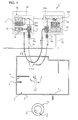
Figure 1 is a schematic illustration of a system for surveillance of an area within which people move provided according to the dictates of the present invention; and -
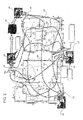
Figure 2 illustrates a variant to the system ofFigure 1 . - In
Figure 1 designated as a whole by (1) is a system for surveillance of a delimited area (2) within which people move (3). - The area (2) can be conveniently an airport or sea-port terminal, a railway station, a shopping centre, a large department store, or an industrial plant, and comprises at least one compartment (4) delimited by walls (5) (illustrated schematically) and provided with entrances (6) and exits (7).
- The system (1) comprises at least one hollow optical fibre (10) (of a commercially available type) configured to extend through the area (2). The hollow optical fibre (10), preferably with a circular cross section, defines an internal channel (11), the hollow optical fibre being provided throughout its length with a plurality of radial holes (12) spaced apart and designed to set the internal channel (11) in communication with the outside of the fibre (10). The radial holes (12) are conveniently provided obtained using technologies of a known type, typically laser drilling.
- The hollow optical fibre could also be flanked by a capillary tube CT, which is connected to one end of the fibre and is set alongside it and is provided throughout its length with a plurality of holes that set an internal channel of the tube in communication with the outside of the tube itself.
- An example of hollow optical fibre is described in the patent application No.
PCT WO 01/94915 WO2009157977 discloses an environmental sensor consisting of one hollow optical fibre provided with slots that set an internal channel of the fibre in communication with the outside of the fibre. - The optical fibre (10) can be rested on the ground, fixed to the walls (5) or else to the ceiling of the area (2), thus adapting to the shape of the compartment (4). Typically the optical fibre (10) can be set in a ventilation duct (not illustrated) of the area (2). The length of the fibre may range from a few metres up to some tens of metres, also by coupling several lengths of hollow optical fibre.
- Preferably, the transmittance of the fibre (10) must be such that the signal losses are less than 1 dB/m throughout the operating spectral bandwidth (3 to 15 µm).
- The losses due to any bending of the fibre should be less than 1 dB/turn for bends at 90° with radius of curvature greater than 10 cm. If the fibre is laid out, it enables a higher sensitivity of the sensor, as compared to other solutions, thanks to a lower optical loss.
- A first end (10a) of the optical fibre (10) is associated to a first connector (15) designed to enable supply of a flow of air within a hollow fibre via a micro-pump (16) of a known type and to enable passage of the optical signal entering the first end of the fibre.
- A second end (10b) of the optical fibre (10) is associated to a second connector (17) designed to enable inlet or outlet of the air conveyed in the internal channel (11) by the micro pump (16) and to enable passage of the signal leaving the second end of the fibre.
- There is thus obtained a flow of air drawn in from outside the hollow optical fibre along the internal channel (11) from the first end (10a) to the second end (10b) or vice versa. Transmission of the optical signal is moreover enabled from the source (20) to the sensor (24) through the inside of the hollow optical fibre.
- The micro-pump (16) is configured for enabling rather fast passage of the air within the
fibre 10 with uniform speed, thus minimizing the noise induced by the flow of air within the fibre. The hollow optical fibre (10) and/or the capillary tube CT (if provided) can be provided with a duct that contains them, said duct being able to filter the particulate or to contain the passage of possible interferents towards the inside of the hollow optical fibre and of the capillary tube CT (if present). - The system (1) comprises a generator device (20) for generating an optical signal designed to supply the signal produced to the first end (10a) of the hollow optical fibre (10). For example, the generator device (20) comprises a laser source such as to generate an optical signal with adjustable wavelength, which is guided, by means of two mirrors (22a), (22b) and a beam splitter (23) set between the mirrors, to the first connector (15).
- The system (1) further comprises a sensor (24) (of a known type) designed to detect the optical signal present at the second end (10b) of the fibre (10). Said signal is sent to the sensor (24) by means of a pair of mirrors (25a), (25b) that direct towards the sensor (24) the optical signal that exits from the second connector (17). The sensor (24) and the hollow optical fibre (10) preferably operate in the region of the electromagnetic radiation spectrum that ranges from 3 to 15 µm (MID-IR), where the majority of TICs (toxic industrial compounds) and CWAs (chemical war agents) present the most intense characteristic absorption bands (the so-called "fingerprints"). The sensor (24) (which is of a known type) is chosen with short response times.
- The system (1) further comprises a processing unit (30), which receives the measurement signal generated by the sensor (24) and a possible reference signal generated by the sensor (21) for processing the optical spectrum of the signal received from the sensor (24).
- The processing unit (30) is moreover designed to examine the spectrum of the optical signal (by means of known infrared-spectroscopy algorithms) in order to detect the presence of characteristic shapes of the spectrum that represent toxic agents that are present in the area (2) and are drawn into the channel (11).
- In this way, in the case of release of a toxic agent (gas or vapour) within the area (2), said agent is drawn in through the holes (12) of the hollow optical fibre or of the capillary tube CT set alongside it within the channel (11) of the optical fibre (10) where the conditions of light transmission are modified. Consequently, the spectrum of the signal received assumes a characteristic shape that indicates the presence of toxic agents. The electronic unit (30) can then issue an alarm warning on a dedicated line (32) in order to activate the procedures of evacuation of the area (2) and restoring safety conditions.
- From the above description the advantages of the system (1) emerge clearly, namely,
- as compared to point sensors, the system (1) enables a substantial reduction of the number of parts and hence of the costs, albeit providing an equivalent or even higher level of coverage;
- as compared to the majority of known systems, the system (1) guarantees a continuous monitoring, and a good sensitivity and selectivity, implementing a wide spectral coverage;
- as compared to point optical sensors, the system (1) is in principle more sensitive, thanks to the optical path provided by the optical fibre and thanks to the higher optical efficiency of transmission of the signal of the hollow optical fibre laid out as compared to point sensors that use the same hollow optical fibre, but wound in a roll, as described in the patent application No.
WO2008061949A1 ; it is estimated that the system (1) can achieve sensitivities in the region of a few ppm without using particularly intense or complex optical sources, and up to a few ppb in the case where laser sources are used; and - finally, the procedures of alignment and calibration of the system (1) are simpler as compared to those required for a system that uses a number of point sensors.
-
Figure 2 illustrates a plurality of hollow optical fibres that extend in the area (2) according to a grid structure. - In greater detail, the following are provided:
- a first de-multiplexer (40) set between the generator device (20) and the first ends (10a) of first fibres (10') for supplying in sequence the optical signal in the first fibres;
- a first optical multiplexer (44), which supplies the optical signals present at the second ends (10b) of the first fibres (10') to a first sensor (24); a possible implementation of the optical multiplexer is constituted by a waveguide system of optical switches;
- a second de-multiplexer (42) set between a second generator device (20) and the first ends (10a) of second fibres (10") for supplying in sequence the optical signal in the second fibres (10");
- the circuit of hollow optical fibres will be equipped with micropumps, one for each fibre, or for each set of fibres supplied by the laser source itself, for adjusting the flow of the air within the hollow optical fibres; a possible but not exclusive implementation consists in a system of pumps and solenoid valves that select the flow from a subset of the optical fibre, for speeding up the analysis of the analyte and/or for increasing the concentration of the gaseous analyte, and restricting the sampling region; and
- a second optical multiplexer 45 (of a known type), which supplies the optical signals present at the second ends (10b) of the second fibres (10") to a second sensor (24).
- The first and second hollow
optical fibres 10', 10" are arranged according to a grid structure in which the first fibres 10' intersect thesecond fibres 10" in different points A, B, C, etc. of the delimitedarea 2. - In the case where a toxic substance is released in a point A, B, C, etc. of the area (2) an alarm is detected for at least one first fibre (10') that passes through a given point and for at least one second fibre (10") that passes through the same point. In this way, the electronic unit (30) can recognize the fibres (10',10") involved to the alarm and trace back to the point of intersection of the fibres (10', 10") that is highly likely to correspond to the point of the area (2) in which the chemical attack has been made.
Claims (4)
- A system for surveillance of a delimited area (2) within which people move, characterized by comprising a plurality of hollow optical fibres (10', 10") that extend in said area according to a grid structure- each hollow optical fibre (10) being provided throughout its length with a plurality of holes (12) that set an internal channel (11) of the fibre in communication with the outside of the fibre;- conveyor means (16) designed to provide a forced flow of air along said internal channel (11) of the hollow optical fibre;- optical sources (20) configured for supplying said optical signal to a first end (10a) of said hollow optical fibre (10);- optical sensors (24) designed to detect the optical signal present at a second end (10b) of the fibre;- optical-coupling means (22a) (22b) (23) (25a) (25b) designed to guide an optical signal from the laser source to one end of the hollow optical fibre and from one end of the hollow optical fibre to the sensors (21) (24);- connection interfaces (15) (17) designed to convey the optical signal and the flow of air at input to and at output from the end of the hollow optical fibre;- a system for acquisition, digitalization, and processing of the signal (30) designed to examine the spectrum of the optical signal detected by said sensor means (24) in order to detect the presence of toxic agents present in the area and drawn into said internal channel (11).
- The system according to Claim 1, wherein multiplexer means or optical switches (40, 42) are provided set between the optical sources (20) and the first ends (10a) of said fibres (10', 10") for supplying in sequence said optical signal in said fibres; there being moreover provided optical-adder means (44, 45) that supply the optical signals present at the second ends of the fibres (10', 10") to said sensors (24).
- The system according to Claim 1, wherein there is provided:- a first plurality of first hollow optical fibres (10') that receive in sequence at their first ends (10a) said optical signal and have second ends (10b) communicating with first sensor means (24); and- a second plurality of second hollow optical fibres (10"), which receive in sequence at their first ends (10a) said optical signal and have second ends (10b) communicating with second sensor means (24);said first and second hollow optical fibres (10', 10") being arranged according to a grid structure in which the first fibres intersect the second fibres in different points of said delimited area;
a system for acquisition, digitalization, and processing of the signal (30) being provided for detecting the pairs of first optical fibres and second optical fibres for which the presence of a toxic agent has been detected and delimiting the point of said area in which said toxic agent is present. - The system according to any one of the preceding claims, wherein said hollow optical fibre is connected to a capillary tube (CT) flanked by the fibre, provided throughout its length with a plurality of holes that set an internal channel of the capillary tube in communication with the outside of the fibre itself.
Priority Applications (1)
| Application Number | Priority Date | Filing Date | Title |
|---|---|---|---|
| PL11717728T PL2542877T3 (en) | 2010-03-05 | 2011-03-04 | System for surveillance of an area within which people move |
Applications Claiming Priority (2)
| Application Number | Priority Date | Filing Date | Title |
|---|---|---|---|
| ITTO2010A000170A IT1398577B1 (en) | 2010-03-05 | 2010-03-05 | SYSTEM FOR SURVEILLANCE OF AN AREA WITHIN WHICH PEOPLE TRANSIT |
| PCT/IB2011/000460 WO2011107868A1 (en) | 2010-03-05 | 2011-03-04 | System for surveillance of an area within which people move |
Publications (2)
| Publication Number | Publication Date |
|---|---|
| EP2542877A1 EP2542877A1 (en) | 2013-01-09 |
| EP2542877B1 true EP2542877B1 (en) | 2015-07-08 |
Family
ID=42831554
Family Applications (1)
| Application Number | Title | Priority Date | Filing Date |
|---|---|---|---|
| EP11717728.7A Active EP2542877B1 (en) | 2010-03-05 | 2011-03-04 | System for surveillance of an area within which people move |
Country Status (10)
| Country | Link |
|---|---|
| US (1) | US8664604B2 (en) |
| EP (1) | EP2542877B1 (en) |
| CN (1) | CN103097874B (en) |
| BR (1) | BR112012022315B8 (en) |
| ES (1) | ES2548282T3 (en) |
| IL (1) | IL221756A (en) |
| IT (1) | IT1398577B1 (en) |
| PL (1) | PL2542877T3 (en) |
| RU (1) | RU2555470C2 (en) |
| WO (1) | WO2011107868A1 (en) |
Families Citing this family (5)
| Publication number | Priority date | Publication date | Assignee | Title |
|---|---|---|---|---|
| FR2981158A1 (en) * | 2011-10-06 | 2013-04-12 | Air Liquide Medical Systems | Gas analysis module for use in anesthesia ventilator for analyzing concentration of compounds present in e.g. inspiratory flow of patient, has hollow optical fiber guiding infra-red signal emitted by transmitter to detector |
| GB2525854B (en) * | 2014-05-02 | 2019-08-07 | Sensorhut Ltd | Sensing methods and apparatus |
| GB201508115D0 (en) * | 2015-05-12 | 2015-06-24 | Univ Cranfield | Hollow fibre waveguide gas cells |
| FR3054916B1 (en) * | 2016-08-02 | 2020-01-24 | Finsecur | SMOKE DETECTOR, SYSTEM AND METHOD FOR SMOKE DETECTION |
| FR3054883B1 (en) * | 2016-08-02 | 2022-11-25 | Finsecur | GAS OR PARTICLE DETECTOR, GAS OR PARTICLE DETECTION SYSTEM AND METHOD |
Family Cites Families (7)
| Publication number | Priority date | Publication date | Assignee | Title |
|---|---|---|---|---|
| US6527398B1 (en) * | 2000-06-08 | 2003-03-04 | Gregory J. Fetzer | Tubular-waveguide gas sample chamber for optical spectrometer, and related methods |
| JP3855153B2 (en) * | 2001-07-05 | 2006-12-06 | 株式会社日立製作所 | Security system |
| US20080262321A1 (en) * | 2004-08-06 | 2008-10-23 | Ramot At Tel Aviv University Ltd. | Early Detection of Harmful Agents: Method, System and Kit |
| CN1800828A (en) * | 2006-01-17 | 2006-07-12 | 杭州电子科技大学 | Infrared gas concentration analyzer |
| EP2035782A2 (en) * | 2006-06-29 | 2009-03-18 | The Board of Trustees of The Leland Stanford Junior University | Fiber optic sensor using a bragg fiber |
| DE102006055157B3 (en) * | 2006-11-22 | 2008-04-30 | Siemens Ag | Optical measuring cell for use in gas monitor, has light source for transferring light into measuring volume that is represented by inner volume of hollow fiber whose inner diameter is less than 1 millimeter |
| US8133593B2 (en) * | 2008-06-26 | 2012-03-13 | Corning Incorporated | Pre-form for and methods of forming a hollow-core slotted PBG optical fiber for an environmental sensor |
-
2010
- 2010-03-05 IT ITTO2010A000170A patent/IT1398577B1/en active
-
2011
- 2011-03-04 EP EP11717728.7A patent/EP2542877B1/en active Active
- 2011-03-04 WO PCT/IB2011/000460 patent/WO2011107868A1/en not_active Ceased
- 2011-03-04 PL PL11717728T patent/PL2542877T3/en unknown
- 2011-03-04 US US13/581,854 patent/US8664604B2/en active Active
- 2011-03-04 CN CN201180012532.1A patent/CN103097874B/en not_active Expired - Fee Related
- 2011-03-04 RU RU2012142340/28A patent/RU2555470C2/en active
- 2011-03-04 BR BR112012022315A patent/BR112012022315B8/en not_active IP Right Cessation
- 2011-03-04 ES ES11717728.7T patent/ES2548282T3/en active Active
-
2012
- 2012-09-03 IL IL221756A patent/IL221756A/en active IP Right Grant
Also Published As
| Publication number | Publication date |
|---|---|
| WO2011107868A9 (en) | 2012-01-19 |
| BR112012022315B8 (en) | 2020-10-27 |
| IT1398577B1 (en) | 2013-03-01 |
| US8664604B2 (en) | 2014-03-04 |
| RU2555470C2 (en) | 2015-07-10 |
| BR112012022315A2 (en) | 2017-10-03 |
| ES2548282T3 (en) | 2015-10-15 |
| BR112012022315B1 (en) | 2019-07-02 |
| CN103097874B (en) | 2015-06-10 |
| IL221756A (en) | 2016-06-30 |
| ITTO20100170A1 (en) | 2011-09-06 |
| PL2542877T3 (en) | 2016-01-29 |
| US20130206991A1 (en) | 2013-08-15 |
| CN103097874A (en) | 2013-05-08 |
| RU2012142340A (en) | 2014-04-10 |
| WO2011107868A1 (en) | 2011-09-09 |
| EP2542877A1 (en) | 2013-01-09 |
Similar Documents
| Publication | Publication Date | Title |
|---|---|---|
| US8664604B2 (en) | System for surveillance of an area within which people move | |
| EP1068686B1 (en) | Networked photonic distribution system for sensing ambient conditions | |
| CN108074368A (en) | The monitoring based on optical fiber of temperature and/or smoke condition at electronic unit | |
| EP3539104B1 (en) | High sensitivity fiber optic based detection | |
| US11067457B2 (en) | Fiber optic based smoke and/or overheat detection and monitoring for aircraft | |
| US11127270B2 (en) | High sensitivity fiber optic based detection | |
| EP3539108B1 (en) | High sensitivity fiber optic based detection | |
| EP3539105B1 (en) | High sensitivity fiber optic based detection | |
| EP3539100B1 (en) | High sensitivity fiber optic based detection | |
| EP3539109A2 (en) | High sensitivity fiber optic based detection | |
| JP4151530B2 (en) | Disaster prevention system for underground space | |
| EP3821415B1 (en) | Enhanced robustness for high sensitivity fiber optic smoke detection | |
| EP3539102B1 (en) | High sensitivity fiber optic based detection | |
| US11293865B2 (en) | High sensitivity fiber optic based detection | |
| US11087606B2 (en) | High sensitivity fiber optic based detection | |
| EP3539107B1 (en) | High sensitivity fiber optic based detection | |
| EP3539106B1 (en) | High sensitivity fiber optic based detection | |
| RU2315230C1 (en) | System for detecting gas leakage from the main pipeline | |
| Lang et al. | Modeling and experiment verification of non-line-of-sight ultraviolet overwater communication channel | |
| Chang et al. | An epidemic model for biological data fusion in ad hoc sensor networks |
Legal Events
| Date | Code | Title | Description |
|---|---|---|---|
| PUAI | Public reference made under article 153(3) epc to a published international application that has entered the european phase |
Free format text: ORIGINAL CODE: 0009012 |
|
| 17P | Request for examination filed |
Effective date: 20120920 |
|
| AK | Designated contracting states |
Kind code of ref document: A1 Designated state(s): AL AT BE BG CH CY CZ DE DK EE ES FI FR GB GR HR HU IE IS IT LI LT LU LV MC MK MT NL NO PL PT RO RS SE SI SK SM TR |
|
| DAX | Request for extension of the european patent (deleted) | ||
| GRAP | Despatch of communication of intention to grant a patent |
Free format text: ORIGINAL CODE: EPIDOSNIGR1 |
|
| INTG | Intention to grant announced |
Effective date: 20150120 |
|
| GRAS | Grant fee paid |
Free format text: ORIGINAL CODE: EPIDOSNIGR3 |
|
| GRAA | (expected) grant |
Free format text: ORIGINAL CODE: 0009210 |
|
| AK | Designated contracting states |
Kind code of ref document: B1 Designated state(s): AL AT BE BG CH CY CZ DE DK EE ES FI FR GB GR HR HU IE IS IT LI LT LU LV MC MK MT NL NO PL PT RO RS SE SI SK SM TR |
|
| REG | Reference to a national code |
Ref country code: GB Ref legal event code: FG4D |
|
| REG | Reference to a national code |
Ref country code: AT Ref legal event code: REF Ref document number: 735786 Country of ref document: AT Kind code of ref document: T Effective date: 20150715 Ref country code: CH Ref legal event code: EP |
|
| REG | Reference to a national code |
Ref country code: IE Ref legal event code: FG4D |
|
| REG | Reference to a national code |
Ref country code: DE Ref legal event code: R096 Ref document number: 602011017668 Country of ref document: DE |
|
| REG | Reference to a national code |
Ref country code: ES Ref legal event code: FG2A Ref document number: 2548282 Country of ref document: ES Kind code of ref document: T3 Effective date: 20151015 |
|
| REG | Reference to a national code |
Ref country code: SE Ref legal event code: TRGR |
|
| REG | Reference to a national code |
Ref country code: AT Ref legal event code: MK05 Ref document number: 735786 Country of ref document: AT Kind code of ref document: T Effective date: 20150708 |
|
| REG | Reference to a national code |
Ref country code: CH Ref legal event code: NV Representative=s name: ANDRE ROLAND S.A., CH |
|
| REG | Reference to a national code |
Ref country code: NL Ref legal event code: FP |
|
| REG | Reference to a national code |
Ref country code: LT Ref legal event code: MG4D |
|
| PG25 | Lapsed in a contracting state [announced via postgrant information from national office to epo] |
Ref country code: GR Free format text: LAPSE BECAUSE OF FAILURE TO SUBMIT A TRANSLATION OF THE DESCRIPTION OR TO PAY THE FEE WITHIN THE PRESCRIBED TIME-LIMIT Effective date: 20151009 Ref country code: LV Free format text: LAPSE BECAUSE OF FAILURE TO SUBMIT A TRANSLATION OF THE DESCRIPTION OR TO PAY THE FEE WITHIN THE PRESCRIBED TIME-LIMIT Effective date: 20150708 Ref country code: LT Free format text: LAPSE BECAUSE OF FAILURE TO SUBMIT A TRANSLATION OF THE DESCRIPTION OR TO PAY THE FEE WITHIN THE PRESCRIBED TIME-LIMIT Effective date: 20150708 Ref country code: NO Free format text: LAPSE BECAUSE OF FAILURE TO SUBMIT A TRANSLATION OF THE DESCRIPTION OR TO PAY THE FEE WITHIN THE PRESCRIBED TIME-LIMIT Effective date: 20151008 Ref country code: FI Free format text: LAPSE BECAUSE OF FAILURE TO SUBMIT A TRANSLATION OF THE DESCRIPTION OR TO PAY THE FEE WITHIN THE PRESCRIBED TIME-LIMIT Effective date: 20150708 |
|
| PG25 | Lapsed in a contracting state [announced via postgrant information from national office to epo] |
Ref country code: RS Free format text: LAPSE BECAUSE OF FAILURE TO SUBMIT A TRANSLATION OF THE DESCRIPTION OR TO PAY THE FEE WITHIN THE PRESCRIBED TIME-LIMIT Effective date: 20150708 Ref country code: AT Free format text: LAPSE BECAUSE OF FAILURE TO SUBMIT A TRANSLATION OF THE DESCRIPTION OR TO PAY THE FEE WITHIN THE PRESCRIBED TIME-LIMIT Effective date: 20150708 Ref country code: IS Free format text: LAPSE BECAUSE OF FAILURE TO SUBMIT A TRANSLATION OF THE DESCRIPTION OR TO PAY THE FEE WITHIN THE PRESCRIBED TIME-LIMIT Effective date: 20151108 Ref country code: HR Free format text: LAPSE BECAUSE OF FAILURE TO SUBMIT A TRANSLATION OF THE DESCRIPTION OR TO PAY THE FEE WITHIN THE PRESCRIBED TIME-LIMIT Effective date: 20150708 Ref country code: PT Free format text: LAPSE BECAUSE OF FAILURE TO SUBMIT A TRANSLATION OF THE DESCRIPTION OR TO PAY THE FEE WITHIN THE PRESCRIBED TIME-LIMIT Effective date: 20151109 |
|
| REG | Reference to a national code |
Ref country code: FR Ref legal event code: PLFP Year of fee payment: 6 |
|
| REG | Reference to a national code |
Ref country code: DE Ref legal event code: R097 Ref document number: 602011017668 Country of ref document: DE |
|
| PG25 | Lapsed in a contracting state [announced via postgrant information from national office to epo] |
Ref country code: CZ Free format text: LAPSE BECAUSE OF FAILURE TO SUBMIT A TRANSLATION OF THE DESCRIPTION OR TO PAY THE FEE WITHIN THE PRESCRIBED TIME-LIMIT Effective date: 20150708 Ref country code: SK Free format text: LAPSE BECAUSE OF FAILURE TO SUBMIT A TRANSLATION OF THE DESCRIPTION OR TO PAY THE FEE WITHIN THE PRESCRIBED TIME-LIMIT Effective date: 20150708 Ref country code: EE Free format text: LAPSE BECAUSE OF FAILURE TO SUBMIT A TRANSLATION OF THE DESCRIPTION OR TO PAY THE FEE WITHIN THE PRESCRIBED TIME-LIMIT Effective date: 20150708 Ref country code: DK Free format text: LAPSE BECAUSE OF FAILURE TO SUBMIT A TRANSLATION OF THE DESCRIPTION OR TO PAY THE FEE WITHIN THE PRESCRIBED TIME-LIMIT Effective date: 20150708 |
|
| PLBE | No opposition filed within time limit |
Free format text: ORIGINAL CODE: 0009261 |
|
| STAA | Information on the status of an ep patent application or granted ep patent |
Free format text: STATUS: NO OPPOSITION FILED WITHIN TIME LIMIT |
|
| PG25 | Lapsed in a contracting state [announced via postgrant information from national office to epo] |
Ref country code: RO Free format text: LAPSE BECAUSE OF FAILURE TO SUBMIT A TRANSLATION OF THE DESCRIPTION OR TO PAY THE FEE WITHIN THE PRESCRIBED TIME-LIMIT Effective date: 20150708 |
|
| 26N | No opposition filed |
Effective date: 20160411 |
|
| PG25 | Lapsed in a contracting state [announced via postgrant information from national office to epo] |
Ref country code: BE Free format text: LAPSE BECAUSE OF NON-PAYMENT OF DUE FEES Effective date: 20160331 Ref country code: SI Free format text: LAPSE BECAUSE OF FAILURE TO SUBMIT A TRANSLATION OF THE DESCRIPTION OR TO PAY THE FEE WITHIN THE PRESCRIBED TIME-LIMIT Effective date: 20150708 |
|
| PG25 | Lapsed in a contracting state [announced via postgrant information from national office to epo] |
Ref country code: MC Free format text: LAPSE BECAUSE OF FAILURE TO SUBMIT A TRANSLATION OF THE DESCRIPTION OR TO PAY THE FEE WITHIN THE PRESCRIBED TIME-LIMIT Effective date: 20150708 Ref country code: LU Free format text: LAPSE BECAUSE OF FAILURE TO SUBMIT A TRANSLATION OF THE DESCRIPTION OR TO PAY THE FEE WITHIN THE PRESCRIBED TIME-LIMIT Effective date: 20160304 |
|
| REG | Reference to a national code |
Ref country code: IE Ref legal event code: MM4A |
|
| PG25 | Lapsed in a contracting state [announced via postgrant information from national office to epo] |
Ref country code: BE Free format text: LAPSE BECAUSE OF FAILURE TO SUBMIT A TRANSLATION OF THE DESCRIPTION OR TO PAY THE FEE WITHIN THE PRESCRIBED TIME-LIMIT Effective date: 20150708 |
|
| PG25 | Lapsed in a contracting state [announced via postgrant information from national office to epo] |
Ref country code: IE Free format text: LAPSE BECAUSE OF NON-PAYMENT OF DUE FEES Effective date: 20160304 |
|
| REG | Reference to a national code |
Ref country code: FR Ref legal event code: PLFP Year of fee payment: 7 |
|
| PG25 | Lapsed in a contracting state [announced via postgrant information from national office to epo] |
Ref country code: MT Free format text: LAPSE BECAUSE OF FAILURE TO SUBMIT A TRANSLATION OF THE DESCRIPTION OR TO PAY THE FEE WITHIN THE PRESCRIBED TIME-LIMIT Effective date: 20150708 |
|
| REG | Reference to a national code |
Ref country code: FR Ref legal event code: PLFP Year of fee payment: 8 |
|
| PG25 | Lapsed in a contracting state [announced via postgrant information from national office to epo] |
Ref country code: CY Free format text: LAPSE BECAUSE OF FAILURE TO SUBMIT A TRANSLATION OF THE DESCRIPTION OR TO PAY THE FEE WITHIN THE PRESCRIBED TIME-LIMIT Effective date: 20150708 Ref country code: HU Free format text: LAPSE BECAUSE OF FAILURE TO SUBMIT A TRANSLATION OF THE DESCRIPTION OR TO PAY THE FEE WITHIN THE PRESCRIBED TIME-LIMIT; INVALID AB INITIO Effective date: 20110304 Ref country code: SM Free format text: LAPSE BECAUSE OF FAILURE TO SUBMIT A TRANSLATION OF THE DESCRIPTION OR TO PAY THE FEE WITHIN THE PRESCRIBED TIME-LIMIT Effective date: 20150708 |
|
| PG25 | Lapsed in a contracting state [announced via postgrant information from national office to epo] |
Ref country code: MT Free format text: LAPSE BECAUSE OF FAILURE TO SUBMIT A TRANSLATION OF THE DESCRIPTION OR TO PAY THE FEE WITHIN THE PRESCRIBED TIME-LIMIT Effective date: 20160331 Ref country code: MK Free format text: LAPSE BECAUSE OF FAILURE TO SUBMIT A TRANSLATION OF THE DESCRIPTION OR TO PAY THE FEE WITHIN THE PRESCRIBED TIME-LIMIT Effective date: 20150708 |
|
| PG25 | Lapsed in a contracting state [announced via postgrant information from national office to epo] |
Ref country code: BG Free format text: LAPSE BECAUSE OF FAILURE TO SUBMIT A TRANSLATION OF THE DESCRIPTION OR TO PAY THE FEE WITHIN THE PRESCRIBED TIME-LIMIT Effective date: 20150708 |
|
| PG25 | Lapsed in a contracting state [announced via postgrant information from national office to epo] |
Ref country code: AL Free format text: LAPSE BECAUSE OF FAILURE TO SUBMIT A TRANSLATION OF THE DESCRIPTION OR TO PAY THE FEE WITHIN THE PRESCRIBED TIME-LIMIT Effective date: 20150708 |
|
| REG | Reference to a national code |
Ref country code: CH Ref legal event code: U11 Free format text: ST27 STATUS EVENT CODE: U-0-0-U10-U11 (AS PROVIDED BY THE NATIONAL OFFICE) Effective date: 20260401 |
|
| PGFP | Annual fee paid to national office [announced via postgrant information from national office to epo] |
Ref country code: SE Payment date: 20260323 Year of fee payment: 16 |
|
| PGFP | Annual fee paid to national office [announced via postgrant information from national office to epo] |
Ref country code: GB Payment date: 20260304 Year of fee payment: 16 |
|
| PGFP | Annual fee paid to national office [announced via postgrant information from national office to epo] |
Ref country code: DE Payment date: 20260320 Year of fee payment: 16 |
|
| PGFP | Annual fee paid to national office [announced via postgrant information from national office to epo] |
Ref country code: IT Payment date: 20260304 Year of fee payment: 16 |
|
| PGFP | Annual fee paid to national office [announced via postgrant information from national office to epo] |
Ref country code: NL Payment date: 20260323 Year of fee payment: 16 |
|
| PGFP | Annual fee paid to national office [announced via postgrant information from national office to epo] |
Ref country code: FR Payment date: 20260323 Year of fee payment: 16 |
|
| PGFP | Annual fee paid to national office [announced via postgrant information from national office to epo] |
Ref country code: TR Payment date: 20260213 Year of fee payment: 16 |
|
| PGFP | Annual fee paid to national office [announced via postgrant information from national office to epo] |
Ref country code: PL Payment date: 20260217 Year of fee payment: 16 |
|
| PGFP | Annual fee paid to national office [announced via postgrant information from national office to epo] |
Ref country code: ES Payment date: 20260414 Year of fee payment: 16 |
|
| PGFP | Annual fee paid to national office [announced via postgrant information from national office to epo] |
Ref country code: CH Payment date: 20260401 Year of fee payment: 16 |