EP2542815B1 - Connecteur à emboîtement pour conduites de fluide - Google Patents
Connecteur à emboîtement pour conduites de fluide Download PDFInfo
- Publication number
- EP2542815B1 EP2542815B1 EP10800901.0A EP10800901A EP2542815B1 EP 2542815 B1 EP2542815 B1 EP 2542815B1 EP 10800901 A EP10800901 A EP 10800901A EP 2542815 B1 EP2542815 B1 EP 2542815B1
- Authority
- EP
- European Patent Office
- Prior art keywords
- plug
- release
- arms
- latching
- release element
- Prior art date
- Legal status (The legal status is an assumption and is not a legal conclusion. Google has not performed a legal analysis and makes no representation as to the accuracy of the status listed.)
- Active
Links
- 238000003892 spreading Methods 0.000 claims description 16
- 238000003780 insertion Methods 0.000 claims description 14
- 230000037431 insertion Effects 0.000 claims description 14
- 238000006073 displacement reaction Methods 0.000 claims description 8
- 238000000034 method Methods 0.000 claims description 3
- 230000007704 transition Effects 0.000 claims 1
- 239000000463 material Substances 0.000 description 6
- 238000013461 design Methods 0.000 description 4
- 230000000977 initiatory effect Effects 0.000 description 3
- 238000009434 installation Methods 0.000 description 3
- 230000002093 peripheral effect Effects 0.000 description 3
- 230000002349 favourable effect Effects 0.000 description 2
- 238000013459 approach Methods 0.000 description 1
- 230000003750 conditioning effect Effects 0.000 description 1
- 230000001419 dependent effect Effects 0.000 description 1
- 238000011161 development Methods 0.000 description 1
- 230000018109 developmental process Effects 0.000 description 1
- 210000005224 forefinger Anatomy 0.000 description 1
- 239000007789 gas Substances 0.000 description 1
- 238000001746 injection moulding Methods 0.000 description 1
- 239000007788 liquid Substances 0.000 description 1
- 238000004519 manufacturing process Methods 0.000 description 1
- 230000013011 mating Effects 0.000 description 1
- 238000002844 melting Methods 0.000 description 1
- 230000008018 melting Effects 0.000 description 1
- 238000005457 optimization Methods 0.000 description 1
- 210000003813 thumb Anatomy 0.000 description 1
Images


Classifications
-
- F—MECHANICAL ENGINEERING; LIGHTING; HEATING; WEAPONS; BLASTING
- F16—ENGINEERING ELEMENTS AND UNITS; GENERAL MEASURES FOR PRODUCING AND MAINTAINING EFFECTIVE FUNCTIONING OF MACHINES OR INSTALLATIONS; THERMAL INSULATION IN GENERAL
- F16L—PIPES; JOINTS OR FITTINGS FOR PIPES; SUPPORTS FOR PIPES, CABLES OR PROTECTIVE TUBING; MEANS FOR THERMAL INSULATION IN GENERAL
- F16L37/00—Couplings of the quick-acting type
- F16L37/08—Couplings of the quick-acting type in which the connection between abutting or axially overlapping ends is maintained by locking members
- F16L37/084—Couplings of the quick-acting type in which the connection between abutting or axially overlapping ends is maintained by locking members combined with automatic locking
- F16L37/098—Couplings of the quick-acting type in which the connection between abutting or axially overlapping ends is maintained by locking members combined with automatic locking by means of flexible hooks
- F16L37/0982—Couplings of the quick-acting type in which the connection between abutting or axially overlapping ends is maintained by locking members combined with automatic locking by means of flexible hooks with a separate member for releasing the coupling
Definitions
- the present invention relates to a connector for media lines (tubing or pipes for any pneumatic or hydraulic flow and / or pressure media, such as gases or liquids), having the features defined in the preamble of claim 1.
- the present invention is based on the object to provide a connector of the type described, which ensures improved performance in a compact design in particular with respect to the handling and spreading force initiation when loosening.
- the release element has axial release arms which extend in the axial direction between the latching arms and the plug shank in the axial direction at least up to the region of the locking cam, wherein the actuating portions are arranged with the inclined surfaces for spreading the latching arms on the release arms, that the Locking arms for releasing be applied in the immediate vicinity of the locking cams with the spreading force.
- the point of initiation of the radial spreading force is displaced axially into the free end region of the latching arms, so that there is a more favorable relationship between the lever arm and the force.
- the latching cam of each latching arm has a central interruption, through which the respective release arm extends, wherein the actuating sections act with the inclined surfaces in the region of the interruptions of the latching cam against the latching arms.
- each latching arm in the region of the locking cam interruption also has a corresponding counter-inclined surface which acts against the inclined surface of the associated release arm.
- each locking arm on its side facing the plug shank have an axial, channel-like guide recess for the respective release arm of the release element.
- This guide recess is constantly in the interruption of the respective locking cam.
- each latching arm in a its free, the locking cams end having axially opposite, integrally connected to the plug part base portion a passage opening for the respective release arm of the release element on.
- the handle portion is arranged on the plug shaft axially opposite side so that it can be easily grasped even in tight installation situations, namely manually with thumb and forefinger or by means of a suitable (commercially available) tool (eg ).
- the design of the invention results in a favorable slim design, wherein the axial displacement of the release element can be chosen almost arbitrarily large, because there is no restriction, such as by the length of the latching arms.
- the handling of the connector according to the invention is simple and convenient.
- the plug part can be taken from a locked into a receiving part and locked against unintentional release position for releasing quite easy in the release element, and by train with a certain unlocking force in the axial direction is initially unlocking by moving the release element and thereby conditional spreading the locking arms.
- train with a rectified removal force then the plug part is released from the receiving part, ie the plug shank is pulled out of the insertion opening, because the release element according to the invention preferably passes in a certain displacement position of a train end stop, so that the force exerted on the release element Switzerland-.
- the release element can be gripped in the region of its handle portion for insertion and thus the entire plug part are inserted, because the release element is preferably limited in plug part insertion direction by a pressure end stop in its axial displacement movement, in a certain relative position, in the the locking arms in an unspread and ready for locking the locking cam starting position.
- the connector shank 4 is in the direction of a connector longitudinal axis X in a plug-in opening 6 of a receiving part 8 inserted, and the plug part 2 is releasably lockable in this inserted position of the plug shank 4 via locking means, ie the connector is locked against accidental release (secured), but the lock can be released (unlocked) to release the connector if necessary.
- a peripheral seal 10 is provided, which is preferably arranged in an outer annular groove on the connector shaft 4.
- the plug part 2 is used to connect (at least) a non-illustrated media line (hose or pipe) to the receiving part 8.
- the plug part 2 consists of a connecting portion which merges on one side into the plug shank 4, and the other side at least one line connection 12 in particular Having a form of a so-called connection mandrel.
- the line connection 12 may also be analogous to the receiving part 8 with a corresponding plug-in opening 6 and an embodiment described further below (see, in particular, the reference numerals 20, 22), so that the plug-in connector 1 z. B. forms an angle adapter.
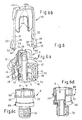
- the connector 1 is formed as an angle connector, wherein the line connection 12 at an angle ⁇ (see Fig.
- the connector 1 may also be a passage connector, wherein the line connection 12 is arranged in the opposite direction according to the longitudinal axis of the plug shank 4. Through the line connection 12, the connecting portion and the plug shank 4 extends an inner continuous channel 14 (see. Fig. 3 . 4 . 5 . 6a and 7 ).
- the plug part 2 as a locking means preferably two diametrically opposed, resilient latching arms 16 which extend in the insertion direction each with a radial distance from the plug shank 4 and radially at their free ends have inwardly projecting locking cam 18.
- the plug part 2 When plugged in - see in particular Fig. 1 . 4 . 7 and 8 - engage behind the locking arms 16 with the locking cams 18 a radial latching step 20 of the receiving part 8; it is a so-called snap-fit positive connection, because the locking cams 18 cooperate with the latching step 20 via effective surfaces with an undercut angle ⁇ 90 °.
- the latching step 20 of the receiving part 8 is preferably formed by a circumferential, radially outwardly extending annular web 22.
- the locking cams 18 have such inclined surfaces that upon insertion of the plug shank 4 in the insertion opening 6 by conditioning on Ring web 22 of the receiving part 8, the latching arms 16 are automatically spring-elastically spread radially outwards until the locking cam 18 snap behind the latching step 20.
- the plug part 2 is thereby secured against accidental loosening. However, the plug part 2 can subsequently also be loosened again, ie pulled out, for which purpose the latching arms 16 can be spread radially outward by means of a release element 24.
- the release element 24 is axially displaceably and captively guided on the plug part 2, and the release element 24 acts in this case with the latching arms 16 together that the latching arms 16 by a - corresponding to the connector longitudinal axis X - axial displacement of the release element 24 in the pull-out direction (arrow 26) of the plug part 2 are radially spread by the release element 24, each with an actuating portion 28 radially from the inside via inclined surfaces 30 with a - acting on the principle of inclined planes-radial spreading force F against the latching arms 16 acts.
- the inclined surfaces 30 of the release element 24 are aligned obliquely to the longitudinal axis, that the operating portions 28 widen in the insertion direction on the inclined surfaces 30 radially outward.
- the release element 24 now has release arms 32, which in the region lying radially between the latching arms 16 and the plug shank 4 extend in the axial direction at least into the region of the latching cams 18.
- the already mentioned actuating portions 28 with the inclined surfaces 30 for spreading the latching arms 16 are arranged on the release arms 32 such that the latching arms 16 are acted upon for releasing in the region of the latching cam 18 with the spreading force F. This is in particular to the sectional views in Fig. 4 and 7 directed.
- each locking cam 18 which extends over a total of a certain peripheral area, a central interruption 34, through which the respective release arm 32 extends.
- the actuating portions 28 of the release arms 32 act with the inclined surfaces 30 in the region of these interruptions 34 of the locking cam 18 against the latching arms sixteenth
- each latching arm 16 also has a corresponding counter-inclined surface (see also in particular the illustration in FIG Fig. 5 ).
- Each locking arm 16 has on its the plug shank 4 facing inside an axial, channel-like guide recess 36 for the respective release arm 32 of the release element 24.
- the guide recess 36 is continuously in the interruption 34 between the locking cam 18 via.
- each release arm 32 extends through the respective guide recess 36 and then further through the interruption 34 of the locking cam 18.
- the channel-like guide grooves 36 may be designed as guide grooves so that the release arms 32 are positively guided.
- the release arms 32 can cause the spreading force F for the locking arms 16 on the inclined surfaces 30 when moving in the direction of arrow 26, they must be supported radially inward.
- the release arms 32 radially inner support surfaces 38 for radially inner support by contact with the plug part 2 and / or on the receiving part 8 during the spreading of the latching arms 16.
- the support surfaces 38 only cooperate with the receiving part 8, in particular by abutting against the annular web 22; see in particular Fig. 4 ,
- Fig. 7 exemplified that the support surfaces 38 abut both on the receiving part in the region of the latching step 20 forming annular web 22 and in addition to the plug part 2 in the region of a radial approach.
- a bearing of the support surfaces 38 may be provided only at suitable portions of the plug part 2.
- each locking arm 16 is in its the locking cam 18 axially opposite region via a base portion 40 integrally connected to the connector part 2.
- a window-like opening 42 for the respective release arm 32 of the release element 24 is now formed.
- the release element 24 is formed as a total of approximately U-shaped slide with two parallel release arms 32 and acting as a handle portion 44 connecting web.
- the release element 24 - see in particular Fig. 6b -
- An inner, web-like guide portion 46 which is slidably guided in a groove-like guide contour 48 of the male part 2 and secured against tilting.
- the guide contour 48 is rounded in the region of the inner angle of the U-shaped guide portion 46.
- a rectangular contour 48a of the groove-like guide 48 and a corresponding rectangular mating contour 46a of the guide portion 46 an extension of the effective guide length.
- the U-shaped configuration of the release element 24 is especially for the angle connector according to Fig. 1 to 6 suitable, since in this case the handle portion 44, the plug part 2 can overlap diametrically to the longitudinal axis of the plug shank 4.
- the passage section 44 connecting the release arms 32 is formed by a ring part enclosing the line connection 12 by a distance concentrically complete (eg closed circular) or partially circumferentially open (eg semicircular).
- the radial distance between the line connection 12 and the annular grip portion 44 is dimensioned such that a line can be plugged onto the connection 12.
- a release element similar to the embodiment according to Fig. 1 to 6 be used when the handle portion 44 relative to the release arms 32 and the center plane defined by these offset to one side, that is cranked so that it is at a sufficient distance next to the Line connection 12 is arranged.
- an offset between the grip portion 44 and the line connection 12 is designed and dimensioned such that a line can be plugged onto the connection 12.
- the release element 24 can also be produced together with the plug part 2 by the method of so-called assembly injection molding.
- the plug part 2 is preferably produced in a first step from a first material, preferably PA, and in a second step the release element 24 is injected from a second material.
- This second material for example PP, PE, POM, has a lower melting temperature than the first material of the plug part 2 and therefore does not enter into a material connection with the first material of the plug part 2.
- the manufacturing process is qualitatively improved because the assembly is simplified and the logistics costs are reduced.
- each release arm 32 of the release element 24 has an axially over the free end of the respective latching arm 16 and the locking cam 18 also extending guide portion 50 with radially inner and outer inclined surfaces 52, 54.
- the outer inclined surfaces 52 serve as insertion bevels in the assembly of the release element 24, d. H. when inserting the release arms 32 through the lead-through openings 42 of the base portions 40 of the latching arms 16.
- the inner inclined surfaces 54 ensures that the release arms 32 can not hinder the insertion process, but that they over the inclined surfaces 54 with their support surfaces 38 for support on the peripheral contour , in particular the annular web 22, the receiving part 8 are guided.
- the release element 24 in plug release direction (arrows 26) by a train stop 56 in his axial displacement movement is limited, in a relative position in which the Locking arms 16 are in a spread release position.
- the train end stop 56 between about T-shaped widened portions 58 in the region of the guide portions 50 of the release arms 32 and free end surfaces of the latching arms 16 is formed.
- Fig. 3 and 5 results after a pulling movement in the direction of arrow 26, the widened portions 58 to rest against the lower end surfaces of the latching arms sixteenth
- the release element 24 is limited in plug insertion direction (arrows 60) by a pressure end stop 62 in its axial displacement movement, in a relative position in which the latching arms 16 are in an unspread and ready for spring latching starting position.
- the pressure end stop 62 is formed on the handle portion 44 facing side of the male part 2 by the engaging in the guide contour 48 guide portion 46.
- the receiving part 8 is formed as a connection adapter 66, wherein this adapter 66 preferably adjacent to the mouth side of the insertion opening 6 first a hexagon 68 and adjacent to the latching step 20 and the insertion opening 6 opposite a Verschraubungsabrough 70.
- this embodiment facilitates the installation of the adapter 66, since the screwing can be done by means of a conventional socket wrench.
- the Verschraubungsabêt 70 is designed as a screw-in with an external thread. This arrangement leads to an advantageous space optimization, since the hexagon 68 is covered by the plug part 2 and thus the space height of the connector 1 is reduced.
- the plug part 2 is formed together with the latching arms 16 as a one-piece molded part made of plastic. The same applies to the release element 24 with its release arms 32nd
- a corrugation or similar contour may be provided on both sides for a better "grip" for a manual assembly.
- the release element 24 can also each have an opening in order to be able to apply a suitable auxiliary tool during assembly and disassembly.
- the connector 1 according to the invention can also have more than two latching arms 16 with a corresponding number of release arms 32.
Landscapes
- Engineering & Computer Science (AREA)
- General Engineering & Computer Science (AREA)
- Mechanical Engineering (AREA)
- Quick-Acting Or Multi-Walled Pipe Joints (AREA)
Claims (15)
- Raccord par emboîtement (1) pour conduites de fluide, constitué d'un élément de déblocage (24) et d'une partie à emboîter (2) dotée d'une tige à emboîter (4) pouvant être insérée dans une ouverture d'emboîtement (6) d'une partie de réception (8) et pouvant être bloquée de manière amovible par l'intermédiaire de moyens de verrouillage, dans lequel la partie à emboîter (2) présente, en tant que moyens de verrouillage, au moins deux bras d'enclenchement (16) élastiques, qui s'étendent dans la direction d'emboîtement respectivement à une distance radiale par rapport à la tige à emboîter (4) et qui présentent, au niveau de leurs extrémités libres, des cames d'enclenchement (18) faisant saillie radialement vers l'intérieur servant à revenir en prise par l'arrière par enclenchement avec un cran d'enclenchement (20) de la partie de réception (8), dans lequel les bras d'enclenchement (16) peuvent être écartés radialement vers l'extérieur au moyen de l'élément de déblocage (24) afin de débloquer le blocage de la partie à emboîter (2), dans lequel l'élément de déblocage (24) est disposé au niveau de la partie à emboîter (2) de manière à pouvoir être déplacé axialement par coulissement et coopère avec les bras d'enclenchement (16) de telle manière que les bras d'enclenchement (16) sont écartés radialement du fait d'un déplacement par coulissement de l'élément de déblocage (24) en ce que l'élément de déblocage (24) doté respectivement d'une section d'actionnement (28) agit radialement de l'intérieur par l'intermédiaire de faces obliques (30) avec une force d'écartement (F) à l'encontre des bras d'enclenchement (16), dans lequel l'élément de déblocage (24) présente, dans la zone se trouvant radialement entre les bras d'enclenchement (16) et la tige à emboîter (4), des bras de déblocage (32) s'étendant axialement au moins jusque dans la zone des cames d'enclenchement (18), dans lequel les sections d'actionnement (28) dotées des faces obliques (30) servant à écarter les bras d'enclenchement (16) sont disposées au niveau des bras de déblocage (32) de telle manière que les bras d'enclenchement (16) destinés à être débloqués dans la zone des cames d'enclenchement (18) sont soumis à l'action de la force d'écartement (F), caractérisé en ce que la came d'enclenchement (18) de chaque bras d'enclenchement (16) présente une zone d'interruption (34) centrale, à travers laquelle le bras de déblocage respectif (32) s'étend, dans lequel les sections d'actionnement (28) dotées des faces obliques (30) agissent à proximité des zones d'interruption (34) des cames d'enclenchement (18) à l'encontre des bras d'enclenchement (16).
- Raccord par emboîtement selon la revendication 1,
caractérisé en ce que chaque bras d'enclenchement (16) présente, sur son côté intérieur tourné vers la tige à emboîter (4), un creux de guidage (36) axiale de type canal pour le bras de déblocage (32) respectif de l'élément de déblocage (24). - Raccord par emboîtement selon la revendication 1 ou 2,
caractérisé en ce que les bras de déblocage (32) présentent des faces d'appui (38) radialement intérieures destinées à venir en appui radialement au niveau de la partie à emboîter (2) et/ou au niveau de la partie de réception (8) au cours de l'opération d'écartement des bras d'enclenchement (16). - Raccord par emboîtement selon l'une quelconque des revendications 1 à 3,
caractérisé en ce que chaque bras d'enclenchement (16) présente, dans une section de base (40), faisant face axialement à son extrémité libre présentant la came d'enclenchement (18), reliée d'un seul tenant à la partie à emboîter (2), une ouverture de passage (42) pour le bras de déblocage (32) respectif de l'élément de déblocage (24). - Raccord par emboîtement selon l'une quelconque des revendications 1 à 4,
caractérisé en ce que les bras de déblocage (32) s'étendant les uns par rapport aux autres de manière parallèle sont reliés d'un seul tenant par l'intermédiaire d'une section de préhension (44) dans la zone faisant face axialement aux cames d'enclenchement (18) à l'extérieur des bras d'enclenchement (16). - Raccord par emboîtement selon l'une quelconque des revendications 1 à 5,
caractérisé en ce que l'élément de déblocage (24) est réalisé de manière à présenter approximativement une forme de U avec deux bras de déblocage (32) et une barrette d'assemblage reliant lesdits deux bras de déblocage, faisant office de section de préhension (44). - Raccord par emboîtement selon l'une quelconque des revendications 1 à 6,
caractérisé en ce que l'élément de déblocage (24) présente une section de guidage (46) intérieure de type barrette, qui est guidée dans un contour de guidage (48) de type rainure de la partie à emboîter (2) de manière à pouvoir être déplacé par coulissement et sans basculement. - Raccord par emboîtement selon l'une quelconque des revendications 6 ou 7,
caractérisé en ce que la partie à emboîter (2) est réalisée sous la forme d'un raccord d'angle et présente au moins un raccordement de conduite (12), qui s'étend par rapport à l'axe longitudinal de la tige à emboîter (4) selon un angle (α) inférieur à 180°, en particulier selon un angle d'environ 90°, dans lequel la barrette d'assemblage, formant la section de préhension (44), de l'élément de déblocage (24) chevauche la zone de transition entre la tige à emboîter (4) et le raccordement de conduite (12) de manière diamétrale par rapport à l'axe longitudinal de la tige à emboîter. - Raccord par emboîtement selon la revendication 5,
caractérisé en ce que la partie à emboîter (2) est réalisée sous la forme d'un raccord de passage doté d'un raccordement de conduite (12), qui s'étend dans une direction opposée selon l'axe longitudinal de la tige à emboîter (4), dans lequel la section de préhension (44), reliant les bras de déblocage (32), de l'élément de déblocage (24) est soit formée par une partie annulaire entourant de manière concentrique à une certaine distance radiale le raccordement de conduite (12) soit disposée de manière décalée par rapport aux bras de déblocage (32) et à un axe longitudinal de raccord (X) dans une zone espacée à proximité du raccordement de conduite (12). - Raccord par emboîtement selon l'une quelconque des revendications 1 à 9,
caractérisé en ce que chaque bras de déblocage (32) de l'élément de déblocage (24) présente une section de guidage (50) s'étendant axialement au-delà de l'extrémité libre du bras d'enclenchement (16) et de la came d'enclenchement (18), dotée de faces obliques (52, 54) radialement intérieures et extérieures. - Raccord par emboîtement selon l'une quelconque des revendications 1 à 10,
caractérisé en ce que le mouvement de déplacement par coulissement de l'élément de déblocage (24) est limité, dans la direction de déblocage (26) de la partie à emboîter, par une butée de traction-de fin de course (56), à savoir dans une position relative, dans laquelle les bras d'enclenchement (16) se trouvent dans une position de déblocage à l'état écarté. - Raccord par emboîtement selon la revendication 11,
caractérisé en ce que la butée de traction-de fin de course (56) est formée entre des extrémités (58), s'élargissant de manière à présenter approximativement une forme de T, dépassant axialement les bras d'enclenchement (16), des bras de déblocage (32) et des faces d'extrémité libres des bras d'enclenchement (16). - Raccord par emboîtement selon l'une quelconque des revendications 1 à 12,
caractérisé en ce que le mouvement de déplacement par coulissement de l'élément de déblocage (24) est limité dans la direction d'insertion (60) de la partie à emboîter par une butée de pression-de fin de course (62), c'est à dire dans une position relative, dans laquelle les bras d'enclenchement (16) se trouvent dans une position de départ à l'état non écarté et appropriée pour l'enclenchement des cames d'enclenchement (18). - Raccord par emboîtement selon la revendication 13,
caractérisé en ce que la butée de pression-fin de course (62) est formée par des faces d'appui de l'élément de déblocage (24) et de la partie à emboîter (2) en particulier dans la zone se trouvant à l'extérieur des bras d'enclenchement (16) sur le côté faisant face aux cames d'enclenchement (18). - Raccord par emboîtement selon l'une quelconque des revendications 1 à 14,
caractérisé en ce que la partie de réception (8) est réalisée sous la forme d'une composante d'un groupe quelconque ou sous la forme d'un adaptateur d'assemblage (66), dans lequel l'adaptateur (66) présente, de préférence dans le prolongement du côté d'embouchure de l'ouverture d'emboîtement (6), en premier lieu un dispositif d'application de force pour outil réalisé de préférence sous la forme d'un hexagone mâle (68) et un cran d'arrêt (20) adjacent audit dispositif d'application de force ainsi qu'une section de vissage (70) faisant face à l'ouverture d'emboîtement (6).
Applications Claiming Priority (2)
| Application Number | Priority Date | Filing Date | Title |
|---|---|---|---|
| DE102010010522A DE102010010522B4 (de) | 2010-03-05 | 2010-03-05 | Steckverbinder für Medienleitungen |
| PCT/EP2010/068806 WO2011107174A1 (fr) | 2010-03-05 | 2010-12-03 | Connecteur à emboîtement pour conduites de fluide |
Publications (2)
| Publication Number | Publication Date |
|---|---|
| EP2542815A1 EP2542815A1 (fr) | 2013-01-09 |
| EP2542815B1 true EP2542815B1 (fr) | 2014-03-05 |
Family
ID=43919767
Family Applications (1)
| Application Number | Title | Priority Date | Filing Date |
|---|---|---|---|
| EP10800901.0A Active EP2542815B1 (fr) | 2010-03-05 | 2010-12-03 | Connecteur à emboîtement pour conduites de fluide |
Country Status (4)
| Country | Link |
|---|---|
| US (1) | US8662543B2 (fr) |
| EP (1) | EP2542815B1 (fr) |
| DE (1) | DE102010010522B4 (fr) |
| WO (1) | WO2011107174A1 (fr) |
Families Citing this family (10)
| Publication number | Priority date | Publication date | Assignee | Title |
|---|---|---|---|---|
| JP5761931B2 (ja) * | 2010-06-15 | 2015-08-12 | 株式会社ニフコ | コネクタ |
| DE102012104288A1 (de) * | 2012-05-16 | 2013-11-21 | Voss Automotive Gmbh | "Steckverbindung für Fluid-Leitungen und Halteteil für eine derartige Steckverbindung" |
| DE102014107655B4 (de) * | 2014-05-30 | 2024-07-11 | Voss Automotive Gmbh | Steckverbinder für Fluidleitungen mit innenliegender Adapterhülse |
| US10337656B2 (en) * | 2015-10-27 | 2019-07-02 | Ford Global Technologies, Llc | Quick connect with visual indicator |
| US10240701B2 (en) * | 2017-02-02 | 2019-03-26 | Caterpillar Inc. | Hose coupler for transferring fluids from a machine |
| DE102017122309A1 (de) * | 2017-09-26 | 2019-03-28 | Voss Automotive Gmbh | Konfektionierte Medienleitung |
| FR3073598B1 (fr) | 2017-11-10 | 2019-10-25 | A. Raymond Et Cie | Raccord a deconnexion par traction sur une bague |
| DE102018208826A1 (de) * | 2018-06-05 | 2019-12-05 | Inficon Gmbh | Verbindungsvorrichtung zum Verbinden eines Gassensors |
| DE102019107909A1 (de) * | 2019-03-27 | 2020-10-01 | Voss Fluid Gmbh | Steckverbindung für Fluid-Leitungen |
| US11498087B2 (en) * | 2019-06-28 | 2022-11-15 | Medmix Switzerland Ag | Connecting device |
Family Cites Families (18)
| Publication number | Priority date | Publication date | Assignee | Title |
|---|---|---|---|---|
| US2899215A (en) * | 1959-08-11 | ardito | ||
| US940678A (en) * | 1909-04-24 | 1909-11-23 | William A Mackenzie | Automatic pipe-coupling. |
| US1966718A (en) * | 1933-05-29 | 1934-07-17 | Ideal Hose Coupling Co Inc | Hose coupling |
| US4101149A (en) * | 1974-06-17 | 1978-07-18 | Henry Fleischer | Coupling device |
| US4875711A (en) * | 1988-04-25 | 1989-10-24 | Usui Kokusai Sangyo Kaisha Ltd. | Slender tube connector |
| US5131687A (en) * | 1989-05-29 | 1992-07-21 | Autobrevets | Device for making a sealed connection between a tube and a flexible hose |
| DE9411111U1 (de) | 1994-07-08 | 1994-09-08 | Armaturenfabrik Hermann Voss GmbH + Co, 51688 Wipperfürth | Steckverbinder für Schlauch- und/oder Rohrleitungen |
| US5799986A (en) * | 1994-12-21 | 1998-09-01 | Flex Technologies, Inc. | Connector assembly and method of manufacture |
| JP2001032985A (ja) * | 1999-07-21 | 2001-02-06 | Tokyo Gas Co Ltd | 配管継手 |
| DE20212488U1 (de) * | 2002-08-14 | 2003-12-24 | Voss Automotive Gmbh | Steckkupplung für fluidische Systeme |
| US7044506B2 (en) * | 2003-08-07 | 2006-05-16 | Xiamen Lota International Co., Ltd. | Quick connector assembly |
| DE102004004364B3 (de) * | 2004-01-29 | 2005-01-27 | Rasmussen Gmbh | Steckkupplung zum Verbinden einer Fluidleitung mit einem Rohr |
| DE102005011777B4 (de) * | 2005-03-11 | 2008-04-17 | Pass Gmbh & Co. Kg | Schnellkupplung für ein Rohrsystem |
| DE202005015966U1 (de) | 2005-10-10 | 2007-02-15 | Voss Automotive Gmbh | Steckverbinder für Medienleitungen |
| DE102006013899B3 (de) * | 2006-03-25 | 2006-11-30 | Rasmussen Gmbh | Steckkupplung |
| US7658420B2 (en) * | 2006-07-13 | 2010-02-09 | Parker-Hannifin Corporation | Quick-connect fitting with unlocking ring |
| DE102007032324B4 (de) * | 2007-07-11 | 2012-10-31 | A. Raymond Et Cie | Fluidleitungskupplung |
| FR2929679B1 (fr) * | 2008-04-07 | 2010-04-23 | Raymond A & Cie | Raccord de connecteur pour conduits de fluide avec un ressort en fil metallique |
-
2010
- 2010-03-05 DE DE102010010522A patent/DE102010010522B4/de not_active Expired - Fee Related
- 2010-12-03 WO PCT/EP2010/068806 patent/WO2011107174A1/fr active Application Filing
- 2010-12-03 EP EP10800901.0A patent/EP2542815B1/fr active Active
- 2010-12-03 US US13/582,812 patent/US8662543B2/en not_active Expired - Fee Related
Also Published As
| Publication number | Publication date |
|---|---|
| US8662543B2 (en) | 2014-03-04 |
| DE102010010522B4 (de) | 2012-10-25 |
| DE102010010522A1 (de) | 2011-10-06 |
| EP2542815A1 (fr) | 2013-01-09 |
| WO2011107174A1 (fr) | 2011-09-09 |
| US20120326436A1 (en) | 2012-12-27 |
Similar Documents
| Publication | Publication Date | Title |
|---|---|---|
| EP2542815B1 (fr) | Connecteur à emboîtement pour conduites de fluide | |
| EP2224156B1 (fr) | Raccord à emboitement pour conduites de fluide | |
| EP3149384B1 (fr) | Raccord enfichable pour conduites de fluide, muni d'une douille d'adaptation intérieure | |
| EP2864685B1 (fr) | Dispositif de raccordement pour conduites | |
| EP1781979B1 (fr) | Raccord emboitable pour conduites fluidiques | |
| EP2724065B1 (fr) | Raccord de tuyau flexible et système de tuyau flexible correspondant | |
| DE102014102662B4 (de) | Steckverbindung für Fluid-Leitungen und Halteteil für eine derartige Steckverbindung | |
| EP2606270B1 (fr) | Organe de verrouillage pour un élément d'accouplement et élément d'accouplement doté d'un tel organe de verrouillage | |
| EP1567800B1 (fr) | Raccord de conduite emboitable et blocable | |
| DE102013100772A1 (de) | Steckverbindung für Fluid-Leitungen und Halteteil für eine derartige Steckverbindung | |
| DE102005038439A1 (de) | Steckverbindung für Fluid-Leitungen | |
| EP2281136B1 (fr) | Raccord à emboîtement pour conduites de fluide | |
| EP1549873B1 (fr) | Element de reception de connecteur enfichable pour fluides | |
| EP0691501B1 (fr) | Raccord à fiche pour tuyaux flexibles et/ou tuyaux rigides | |
| EP1233227B9 (fr) | Raccord enfichable pour tuyaux pour fluide | |
| DE102009008609B4 (de) | Steckverbindung für Fluid-Leitungen | |
| DE102006026162B4 (de) | Anschlussvorrichtung für Medienleitungen | |
| DE202004012794U1 (de) | Steckverbindung für Fluid-Leitungen |
Legal Events
| Date | Code | Title | Description |
|---|---|---|---|
| PUAI | Public reference made under article 153(3) epc to a published international application that has entered the european phase |
Free format text: ORIGINAL CODE: 0009012 |
|
| 17P | Request for examination filed |
Effective date: 20120720 |
|
| AK | Designated contracting states |
Kind code of ref document: A1 Designated state(s): AL AT BE BG CH CY CZ DE DK EE ES FI FR GB GR HR HU IE IS IT LI LT LU LV MC MK MT NL NO PL PT RO RS SE SI SK SM TR |
|
| DAX | Request for extension of the european patent (deleted) | ||
| GRAP | Despatch of communication of intention to grant a patent |
Free format text: ORIGINAL CODE: EPIDOSNIGR1 |
|
| INTG | Intention to grant announced |
Effective date: 20130924 |
|
| GRAS | Grant fee paid |
Free format text: ORIGINAL CODE: EPIDOSNIGR3 |
|
| GRAA | (expected) grant |
Free format text: ORIGINAL CODE: 0009210 |
|
| AK | Designated contracting states |
Kind code of ref document: B1 Designated state(s): AL AT BE BG CH CY CZ DE DK EE ES FI FR GB GR HR HU IE IS IT LI LT LU LV MC MK MT NL NO PL PT RO RS SE SI SK SM TR |
|
| REG | Reference to a national code |
Ref country code: GB Ref legal event code: FG4D Free format text: NOT ENGLISH |
|
| REG | Reference to a national code |
Ref country code: CH Ref legal event code: EP |
|
| REG | Reference to a national code |
Ref country code: AT Ref legal event code: REF Ref document number: 655131 Country of ref document: AT Kind code of ref document: T Effective date: 20140315 |
|
| RIN2 | Information on inventor provided after grant (corrected) |
Inventor name: LECHNER, MARTIN Inventor name: ZENSES, FRANK Inventor name: ROSOWSKI, EVELIN |
|
| REG | Reference to a national code |
Ref country code: IE Ref legal event code: FG4D Free format text: LANGUAGE OF EP DOCUMENT: GERMAN |
|
| REG | Reference to a national code |
Ref country code: DE Ref legal event code: R096 Ref document number: 502010006312 Country of ref document: DE Effective date: 20140410 |
|
| REG | Reference to a national code |
Ref country code: DE Ref legal event code: R083 Ref document number: 502010006312 Country of ref document: DE |
|
| REG | Reference to a national code |
Ref country code: NL Ref legal event code: VDEP Effective date: 20140305 |
|
| PG25 | Lapsed in a contracting state [announced via postgrant information from national office to epo] |
Ref country code: LT Free format text: LAPSE BECAUSE OF FAILURE TO SUBMIT A TRANSLATION OF THE DESCRIPTION OR TO PAY THE FEE WITHIN THE PRESCRIBED TIME-LIMIT Effective date: 20140305 Ref country code: NO Free format text: LAPSE BECAUSE OF FAILURE TO SUBMIT A TRANSLATION OF THE DESCRIPTION OR TO PAY THE FEE WITHIN THE PRESCRIBED TIME-LIMIT Effective date: 20140605 |
|
| REG | Reference to a national code |
Ref country code: LT Ref legal event code: MG4D |
|
| PG25 | Lapsed in a contracting state [announced via postgrant information from national office to epo] |
Ref country code: FI Free format text: LAPSE BECAUSE OF FAILURE TO SUBMIT A TRANSLATION OF THE DESCRIPTION OR TO PAY THE FEE WITHIN THE PRESCRIBED TIME-LIMIT Effective date: 20140305 Ref country code: CY Free format text: LAPSE BECAUSE OF FAILURE TO SUBMIT A TRANSLATION OF THE DESCRIPTION OR TO PAY THE FEE WITHIN THE PRESCRIBED TIME-LIMIT Effective date: 20140305 Ref country code: SE Free format text: LAPSE BECAUSE OF FAILURE TO SUBMIT A TRANSLATION OF THE DESCRIPTION OR TO PAY THE FEE WITHIN THE PRESCRIBED TIME-LIMIT Effective date: 20140305 |
|
| PG25 | Lapsed in a contracting state [announced via postgrant information from national office to epo] |
Ref country code: RS Free format text: LAPSE BECAUSE OF FAILURE TO SUBMIT A TRANSLATION OF THE DESCRIPTION OR TO PAY THE FEE WITHIN THE PRESCRIBED TIME-LIMIT Effective date: 20140305 Ref country code: LV Free format text: LAPSE BECAUSE OF FAILURE TO SUBMIT A TRANSLATION OF THE DESCRIPTION OR TO PAY THE FEE WITHIN THE PRESCRIBED TIME-LIMIT Effective date: 20140305 Ref country code: HR Free format text: LAPSE BECAUSE OF FAILURE TO SUBMIT A TRANSLATION OF THE DESCRIPTION OR TO PAY THE FEE WITHIN THE PRESCRIBED TIME-LIMIT Effective date: 20140305 |
|
| PG25 | Lapsed in a contracting state [announced via postgrant information from national office to epo] |
Ref country code: IS Free format text: LAPSE BECAUSE OF FAILURE TO SUBMIT A TRANSLATION OF THE DESCRIPTION OR TO PAY THE FEE WITHIN THE PRESCRIBED TIME-LIMIT Effective date: 20140705 Ref country code: CZ Free format text: LAPSE BECAUSE OF FAILURE TO SUBMIT A TRANSLATION OF THE DESCRIPTION OR TO PAY THE FEE WITHIN THE PRESCRIBED TIME-LIMIT Effective date: 20140305 Ref country code: BG Free format text: LAPSE BECAUSE OF FAILURE TO SUBMIT A TRANSLATION OF THE DESCRIPTION OR TO PAY THE FEE WITHIN THE PRESCRIBED TIME-LIMIT Effective date: 20140605 Ref country code: EE Free format text: LAPSE BECAUSE OF FAILURE TO SUBMIT A TRANSLATION OF THE DESCRIPTION OR TO PAY THE FEE WITHIN THE PRESCRIBED TIME-LIMIT Effective date: 20140305 Ref country code: NL Free format text: LAPSE BECAUSE OF FAILURE TO SUBMIT A TRANSLATION OF THE DESCRIPTION OR TO PAY THE FEE WITHIN THE PRESCRIBED TIME-LIMIT Effective date: 20140305 Ref country code: RO Free format text: LAPSE BECAUSE OF FAILURE TO SUBMIT A TRANSLATION OF THE DESCRIPTION OR TO PAY THE FEE WITHIN THE PRESCRIBED TIME-LIMIT Effective date: 20140305 |
|
| PG25 | Lapsed in a contracting state [announced via postgrant information from national office to epo] |
Ref country code: SK Free format text: LAPSE BECAUSE OF FAILURE TO SUBMIT A TRANSLATION OF THE DESCRIPTION OR TO PAY THE FEE WITHIN THE PRESCRIBED TIME-LIMIT Effective date: 20140305 Ref country code: PL Free format text: LAPSE BECAUSE OF FAILURE TO SUBMIT A TRANSLATION OF THE DESCRIPTION OR TO PAY THE FEE WITHIN THE PRESCRIBED TIME-LIMIT Effective date: 20140305 Ref country code: ES Free format text: LAPSE BECAUSE OF FAILURE TO SUBMIT A TRANSLATION OF THE DESCRIPTION OR TO PAY THE FEE WITHIN THE PRESCRIBED TIME-LIMIT Effective date: 20140305 |
|
| REG | Reference to a national code |
Ref country code: DE Ref legal event code: R097 Ref document number: 502010006312 Country of ref document: DE |
|
| PG25 | Lapsed in a contracting state [announced via postgrant information from national office to epo] |
Ref country code: PT Free format text: LAPSE BECAUSE OF FAILURE TO SUBMIT A TRANSLATION OF THE DESCRIPTION OR TO PAY THE FEE WITHIN THE PRESCRIBED TIME-LIMIT Effective date: 20140707 |
|
| PLBE | No opposition filed within time limit |
Free format text: ORIGINAL CODE: 0009261 |
|
| STAA | Information on the status of an ep patent application or granted ep patent |
Free format text: STATUS: NO OPPOSITION FILED WITHIN TIME LIMIT |
|
| PG25 | Lapsed in a contracting state [announced via postgrant information from national office to epo] |
Ref country code: DK Free format text: LAPSE BECAUSE OF FAILURE TO SUBMIT A TRANSLATION OF THE DESCRIPTION OR TO PAY THE FEE WITHIN THE PRESCRIBED TIME-LIMIT Effective date: 20140305 |
|
| 26N | No opposition filed |
Effective date: 20141208 |
|
| REG | Reference to a national code |
Ref country code: DE Ref legal event code: R097 Ref document number: 502010006312 Country of ref document: DE Effective date: 20141208 |
|
| PG25 | Lapsed in a contracting state [announced via postgrant information from national office to epo] |
Ref country code: SI Free format text: LAPSE BECAUSE OF FAILURE TO SUBMIT A TRANSLATION OF THE DESCRIPTION OR TO PAY THE FEE WITHIN THE PRESCRIBED TIME-LIMIT Effective date: 20140305 |
|
| PG25 | Lapsed in a contracting state [announced via postgrant information from national office to epo] |
Ref country code: BE Free format text: LAPSE BECAUSE OF NON-PAYMENT OF DUE FEES Effective date: 20141231 |
|
| PG25 | Lapsed in a contracting state [announced via postgrant information from national office to epo] |
Ref country code: LU Free format text: LAPSE BECAUSE OF FAILURE TO SUBMIT A TRANSLATION OF THE DESCRIPTION OR TO PAY THE FEE WITHIN THE PRESCRIBED TIME-LIMIT Effective date: 20141203 |
|
| REG | Reference to a national code |
Ref country code: CH Ref legal event code: PL |
|
| GBPC | Gb: european patent ceased through non-payment of renewal fee |
Effective date: 20141203 |
|
| REG | Reference to a national code |
Ref country code: IE Ref legal event code: MM4A |
|
| PG25 | Lapsed in a contracting state [announced via postgrant information from national office to epo] |
Ref country code: CH Free format text: LAPSE BECAUSE OF NON-PAYMENT OF DUE FEES Effective date: 20141231 Ref country code: IE Free format text: LAPSE BECAUSE OF NON-PAYMENT OF DUE FEES Effective date: 20141203 Ref country code: LI Free format text: LAPSE BECAUSE OF NON-PAYMENT OF DUE FEES Effective date: 20141231 Ref country code: GB Free format text: LAPSE BECAUSE OF NON-PAYMENT OF DUE FEES Effective date: 20141203 |
|
| REG | Reference to a national code |
Ref country code: FR Ref legal event code: PLFP Year of fee payment: 6 |
|
| PG25 | Lapsed in a contracting state [announced via postgrant information from national office to epo] |
Ref country code: SM Free format text: LAPSE BECAUSE OF FAILURE TO SUBMIT A TRANSLATION OF THE DESCRIPTION OR TO PAY THE FEE WITHIN THE PRESCRIBED TIME-LIMIT Effective date: 20140305 |
|
| PG25 | Lapsed in a contracting state [announced via postgrant information from national office to epo] |
Ref country code: GR Free format text: LAPSE BECAUSE OF FAILURE TO SUBMIT A TRANSLATION OF THE DESCRIPTION OR TO PAY THE FEE WITHIN THE PRESCRIBED TIME-LIMIT Effective date: 20140606 |
|
| PG25 | Lapsed in a contracting state [announced via postgrant information from national office to epo] |
Ref country code: TR Free format text: LAPSE BECAUSE OF FAILURE TO SUBMIT A TRANSLATION OF THE DESCRIPTION OR TO PAY THE FEE WITHIN THE PRESCRIBED TIME-LIMIT Effective date: 20140305 Ref country code: HU Free format text: LAPSE BECAUSE OF FAILURE TO SUBMIT A TRANSLATION OF THE DESCRIPTION OR TO PAY THE FEE WITHIN THE PRESCRIBED TIME-LIMIT; INVALID AB INITIO Effective date: 20101203 Ref country code: MT Free format text: LAPSE BECAUSE OF FAILURE TO SUBMIT A TRANSLATION OF THE DESCRIPTION OR TO PAY THE FEE WITHIN THE PRESCRIBED TIME-LIMIT Effective date: 20140305 |
|
| REG | Reference to a national code |
Ref country code: FR Ref legal event code: PLFP Year of fee payment: 7 |
|
| REG | Reference to a national code |
Ref country code: AT Ref legal event code: MM01 Ref document number: 655131 Country of ref document: AT Kind code of ref document: T Effective date: 20151203 |
|
| PGFP | Annual fee paid to national office [announced via postgrant information from national office to epo] |
Ref country code: IT Payment date: 20161220 Year of fee payment: 7 |
|
| PG25 | Lapsed in a contracting state [announced via postgrant information from national office to epo] |
Ref country code: AT Free format text: LAPSE BECAUSE OF NON-PAYMENT OF DUE FEES Effective date: 20151203 |
|
| REG | Reference to a national code |
Ref country code: FR Ref legal event code: PLFP Year of fee payment: 8 |
|
| PG25 | Lapsed in a contracting state [announced via postgrant information from national office to epo] |
Ref country code: MK Free format text: LAPSE BECAUSE OF FAILURE TO SUBMIT A TRANSLATION OF THE DESCRIPTION OR TO PAY THE FEE WITHIN THE PRESCRIBED TIME-LIMIT Effective date: 20140305 |
|
| PG25 | Lapsed in a contracting state [announced via postgrant information from national office to epo] |
Ref country code: AL Free format text: LAPSE BECAUSE OF FAILURE TO SUBMIT A TRANSLATION OF THE DESCRIPTION OR TO PAY THE FEE WITHIN THE PRESCRIBED TIME-LIMIT Effective date: 20140305 Ref country code: IT Free format text: LAPSE BECAUSE OF NON-PAYMENT OF DUE FEES Effective date: 20171203 |
|
| PGFP | Annual fee paid to national office [announced via postgrant information from national office to epo] |
Ref country code: MC Payment date: 20211130 Year of fee payment: 12 Ref country code: FR Payment date: 20211216 Year of fee payment: 12 |
|
| PG25 | Lapsed in a contracting state [announced via postgrant information from national office to epo] |
Ref country code: FR Free format text: LAPSE BECAUSE OF NON-PAYMENT OF DUE FEES Effective date: 20221231 |
|
| PGFP | Annual fee paid to national office [announced via postgrant information from national office to epo] |
Ref country code: DE Payment date: 20240226 Year of fee payment: 14 |
|
| PG25 | Lapsed in a contracting state [announced via postgrant information from national office to epo] |
Ref country code: MC Free format text: LAPSE BECAUSE OF NON-PAYMENT OF DUE FEES Effective date: 20230103 |
|
| PG25 | Lapsed in a contracting state [announced via postgrant information from national office to epo] |
Ref country code: MC Free format text: LAPSE BECAUSE OF NON-PAYMENT OF DUE FEES Effective date: 20230103 |