EP2542016A2 - Appareil et procédé d'amélioration des communications de réseau maillé sans fil - Google Patents
Appareil et procédé d'amélioration des communications de réseau maillé sans fil Download PDFInfo
- Publication number
- EP2542016A2 EP2542016A2 EP12173248A EP12173248A EP2542016A2 EP 2542016 A2 EP2542016 A2 EP 2542016A2 EP 12173248 A EP12173248 A EP 12173248A EP 12173248 A EP12173248 A EP 12173248A EP 2542016 A2 EP2542016 A2 EP 2542016A2
- Authority
- EP
- European Patent Office
- Prior art keywords
- directional antennas
- antennas
- directional
- wireless mesh
- omnidirectional
- Prior art date
- Legal status (The legal status is an assumption and is not a legal conclusion. Google has not performed a legal analysis and makes no representation as to the accuracy of the status listed.)
- Withdrawn
Links
Images



Classifications
-
- H—ELECTRICITY
- H04—ELECTRIC COMMUNICATION TECHNIQUE
- H04W—WIRELESS COMMUNICATION NETWORKS
- H04W84/00—Network topologies
- H04W84/18—Self-organising networks, e.g. ad-hoc networks or sensor networks
-
- H—ELECTRICITY
- H04—ELECTRIC COMMUNICATION TECHNIQUE
- H04W—WIRELESS COMMUNICATION NETWORKS
- H04W16/00—Network planning, e.g. coverage or traffic planning tools; Network deployment, e.g. resource partitioning or cells structures
- H04W16/24—Cell structures
- H04W16/28—Cell structures using beam steering
Definitions
- the embodiments described herein relate generally to wireless communications and, more particularly, to methods and apparatus for enhancing communications transmitted via wireless mesh networks.
- Wi-Fi networks are wireless broadband networks, sometimes referred to as Wi-Fi networks, that use the Institute of Electrical and Electronics Engineers (IEEE) standard 802.16 TM .
- IEEE Institute of Electrical and Electronics Engineers
- Wi-Fi networks transmit large volumes of information in excess of 10 Megabits per second (Mbits/sec) and operate in frequency ranges in excess of 2.4 GigaHertz (GHz).
- Mbits/sec Megabits per second
- GHz GigaHertz
- Wi-Fi networks use omnidirectional antennas, directional antennas, or a combination thereof, and are known to have a relatively high rate of power consumption, e.g., in excess of 400 milliamperes (mA) per network device.
- At least some known WMNs use either the ZigBee ® specification or the WirelessHART TM standard, both based on the IEEE standard 802.15.4 TM for low-rate wireless networks.
- Such low-rate wireless networks transmit relatively small volumes of information, e.g., approximately 250 Kilobits per second (Kbits/sec) or less.
- Such low-rate wireless networks operate with frequencies of approximately 2.4 GigaHertz (GHz) or less.
- GHz GigaHertz
- such low-rate wireless networks have a relatively low rate of power consumption as compared to the Wi-Fi networks, e.g., less than 50 mA per device.
- Such low-rate wireless networks are less complex, cost-effective substitutes for the more expensive Wi-Fi networks, and are used in industrial facilities where network traffic is typically limited to sensor information.
- such known low-rate wireless networks use omnidirectional antennas exclusively.
- Such omnidirectional antennas have a range of approximately 25 meters (m) (82 feet (ft)).
- m meters
- ft feet
- many industrial facilities are positioned in regions with rugged landscapes and may require a large number of omnidirectional antennas, each placed within 50 m of each other, thereby increasing costs and complexity of installation.
- some extremely rugged terrain may substantially exclude the use of omnidirectional antennas.
- a wireless mesh network includes at least one data collection device.
- the wireless mesh network also includes a plurality of directional antennas operatively coupled to each other and the at least one data collection device.
- the wireless mesh network is configured to transmit information with a data rate of approximately 250 Kilobits per second (Kbits/sec) or less, and at a frequency of approximately 2.4 GigaHertz (GHz) or less.
- a method of assembling a network includes providing at least one data collection device and providing a plurality of directional antennas. The method also includes operatively coupling at least one of the plurality of directional antennas to the at least one data collection device.
- the network is configured to transmit information with a data rate of approximately 250 Kilobits per second (Kbits/sec) or less, and at a frequency of approximately 2.4 GigaHertz (GHz) or less.
- a monitoring system in yet another aspect, includes at least one sensor measurement device and at least one data collection device.
- the monitoring system also includes a wireless mesh network coupled to the at least one data collection device and the at least one sensor measurement device.
- the wireless mesh network includes a plurality of directional antennas operatively coupled to each other and to the at least one data collection device.
- the wireless mesh network is configured to transmit information with a data rate of approximately 250 Kilobits per second (Kbits/sec) or less, and at a frequency of approximately 2.4 GigaHertz (GHz) or less.
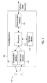
- FIG. 1 is a block diagram of an example computing device 105 that may be used to monitor and/or control the operation of a machine (not shown in FIG. 1 ).
- computing device 105 is a data collection device.
- Computing device 105 includes a memory device 110 and a processor 115 operatively coupled to memory device 110 for executing instructions.
- executable instructions are stored in memory device 110.
- Computing device 105 is configurable to perform one or more operations described herein by programming processor 115.
- processor 115 may be programmed by encoding an operation as one or more executable instructions and providing the executable instructions in memory device 110.
- Processor 115 may include one or more processing units (e.g., in a multicore configuration).
- memory device 110 is one or more devices that enable storage and retrieval of information such as executable instructions and/or other data.
- Memory device 110 may include one or more computer readable media, such as, without limitation, random access memory (RAM), dynamic random access memory (DRAM), static random access memory (SRAM), a solid state disk, a hard disk, read-only memory (ROM), erasable programmable ROM (EPROM), electrically erasable programmable ROM (EEPROM), and/or non-volatile RAM (NVRAM) memory.
- RAM random access memory
- DRAM dynamic random access memory
- SRAM static random access memory
- SSD solid state disk
- ROM read-only memory
- EPROM erasable programmable ROM
- EEPROM electrically erasable programmable ROM
- NVRAM non-volatile RAM
- the terms "software” and “firmware” are interchangeable, and include any computer program stored in memory for execution by personal computers, workstations, clients and servers.
- Memory device 110 may be configured to store operational measurements including, without limitation, vibration readings, field voltage and current readings, field reference setpoints, stator voltage and current readings, rotor speed readings, maintenance tasks, and/or any other type of data.
- processor 115 removes or "purges" data from memory device 110 based on the age of the data. For example, processor 115 may overwrite previously recorded and stored data associated with a subsequent time and/or event. In addition, or alternatively, processor 115 may remove data that exceeds a predetermined time interval.
- computing device 105 includes a presentation interface 120 coupled to processor 115.
- Presentation interface 120 presents information, such as a user interface and/or an alarm, to a user 125.
- presentation interface 120 may include a display adapter (not shown) that may be coupled to a display device (not shown), such as a cathode ray tube (CRT), a liquid crystal display (LCD), an organic LED (OLED) display, and/or an "electronic ink" display.
- presentation interface 120 includes one or more display devices.
- presentation interface 120 may include an audio output device (not shown) (e.g., an audio adapter and/or a speaker) and/or a printer (not shown).
- presentation interface 120 presents an alarm associated with a synchronous machine (not shown in FIG. 1 ), such as by using a human machine interface (HMI) (not shown).
- HMI human machine interface
- computing device 105 includes a user input interface 130.
- user input interface 130 is coupled to processor 115 and receives input from user 125.
- User input interface 130 may include, for example, a keyboard, a pointing device, a mouse, a stylus, a touch sensitive panel (e.g., a touch pad or a touch screen), a gyroscope, an accelerometer, a position detector, and/or an audio input interface (e.g., including a microphone).
- a single component, such as a touch screen may function as both a display device of presentation interface 120 and user input interface 130.
- a communication interface 135 is coupled to processor 115 and is configured to be coupled in communication with one or more other devices, such as a sensor or another computing device 105, and to perform input and output operations with respect to such devices.
- communication interface 135 may include, without limitation, a wired network adapter, a wireless network adapter, a mobile telecommunications adapter, a serial communication adapter, and/or a parallel communication adapter.
- Communication interface 135 may receive data from and/or transmit data to one or more remote devices. For example, a communication interface 135 of one computing device 105 may transmit an alarm to the communication interface 135 of another computing device 105.
- Presentation interface 120 and/or communication interface 135 are both capable of providing information suitable for use with the methods described herein (e.g., to user 125 or another device). Accordingly, presentation interface 120 and communication interface 135 may be referred to as output devices. Similarly, user input interface 130 and communication interface 135 are capable of receiving information suitable for use with the methods described herein and may be referred to as input devices.
- FIG. 2 is block diagram of an example system 200 that may be used to monitor and/or operate a machine 205.
- system 200 is one of a data acquisition system (DAS) and/or a supervisory control and data acquisition system (SCADA).
- Machine 205 may be any industrial equipment for any industrial process, including, without limitation, a chemical process reactor, a heat recovery steam generator, a steam turbine, a gas turbine, a switchyard circuit breaker, and a switchyard transformer.
- machine 205 is a portion of a larger, integrated industrial facility 208.
- Facility 208 may include, without limitation, multiple units of machine 205.
- facility 208 includes rugged geographic terrain including, without limitation, mountainous terrain and extended waterways (not shown).
- system 200 includes a machine controller 210 and a facility controller 215 coupled in communication with each other via a network 220.
- network 220 is a radio mesh network, or more specifically, a low-rate wireless mesh network (WMN) that uses the ZigBee ® specification.
- WSN wireless mesh network
- ZigBee ® is a registered trademark of the ZigBee Alliance, San Ramon, California, U.S.A.
- network 220 is a low-rate WMN that uses the WirelessHART TM standard based on the Highway Addressable Remote Transducer (HART ® ) protocol.
- WirelessHART TM is a trademark and HART ® is a registered trademark of the HART Communication Foundation, Austin, Texas, U.S.A.
- WirelessHART TM Both the WirelessHART TM standard and the ZigBee ® specification are based on the Institute of Electrical and Electronics Engineers (IEEE) standard 802.15.4 TM .
- IEEE Institute of Electrical and Electronics Engineers
- IEEE standard 802.15.4 TM is a trademark of the IEEE Standards Association, Piscataway, New Jersey, U.S.A.
- Low-rate wireless network 220 transmits relatively small volumes of information, i.e., approximately, or less than, 250 Kilobits per second (Kbits/sec) and at a frequency of approximately, or less than, 2.4 GHz.
- Embodiments of network 220 may include, without limitation, the Internet, a local area network (LAN), a wide area network (WAN), a wireless LAN (WLAN), and/or a virtual private network (VPN). While certain operations are described below with respect to particular computing devices 105, it is contemplated that any computing device 105 may perform one or more of the described operations. For example, controller 210 and controller 215 may perform all of the operations below.
- machine controller 210 and facility controller 215 are computing devices 105.
- each computing device 105 is coupled to network 220 via communication interface 135.
- controller 210 is integrated with controller 215.
- Controller 210 interacts with a first operator 225 (e.g., via user input interface 130 and/or presentation interface 120). For example, controller 210 may present information about machine 205, such as alarms, to operator 225.
- Facility controller 215 interacts with a second operator 230 (e.g., via user input interface 130 and/or presentation interface 120). For example, facility controller 215 may present alarms and/or maintenance tasks to second operator 230.
- the term "operator” includes any person in any capacity associated with operating and maintaining facility 208, including, without limitation, shift operations personnel, maintenance technicians, and facility supervisors.
- Machine 205 includes one or more monitoring sensors 235.
- monitoring sensors 235 collect operational measurements including, without limitation, vibration readings, field voltage and current readings, field reference setpoints, stator voltage and current readings, rotor speed readings, maintenance tasks, and/or any other type of data.
- Monitoring sensors 235 repeatedly (e.g., periodically, continuously, and/or upon request) transmits operational measurement readings at the current time.
- monitoring sensors 235 may produce an electrical current between a minimum value (e.g., 4 milliamps (ma)) and a maximum value (e.g., 20 ma).
- the minimum value is representative of an indication that no field current is detected.
- the maximum value is representative of an indication that the highest detectable amount of field current is detected.
- Controller 210 receives and processes the operational measurement readings.
- Facility 208 includes additional monitoring sensors (not shown) similar to monitoring sensors 235 that collect operational data measurements associated with the remainder of facility 208 including, without limitation, data from redundant machines 205 and facility environmental data, including, without limitation, local wind speed, local wind velocity, and local outside temperatures.
- operational data measurements associated with the remainder of facility 208 including, without limitation, data from redundant machines 205 and facility environmental data, including, without limitation, local wind speed, local wind velocity, and local outside temperatures.
- data is transmitted across network 220 and may be accessed by any device capable of accessing network 220 including, without limitation, desktop computers, laptop computers, and personal digital assistants (PDAs) (neither shown).
- PDAs personal digital assistants
- FIG. 3 is a schematic view of machine monitoring system 200.
- computing device 105 is one of machine controller 210 and/or facility controller 215.
- each computing device 105 is coupled to network 220 via communication interface 135.
- Network 220 includes a gateway device 250, wherein device 250 is any gateway device that enables communication within network 220 as described herein, including, without limitation, a router, a modem, and a switch.
- Network 220 also includes a first portion 260 of wireless mesh network 220.
- First portion 260 includes a plurality of radio data nodes with at least one omnidirectional antenna 265, i.e., an OARDN 265.
- Each OARDN 265 is a communication node, and more specifically, is one of a repeater device and, in the example embodiment, is an omnidirectional wireless sensor interface module (wSIM). Alternatively, each OARDN 265 is any omnidirectional wireless sensor interface device. At least one OARDN 265 is operatively coupled in communication with gateway device 250.
- wSIM omnidirectional wireless sensor interface module
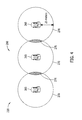
- FIG. 4 is a schematic view of a plurality of OARDNs 265 that may be used with monitoring system 200.
- Each OARDN 265 is operatively coupled in communication with at least one adjacent OARDN 265.
- each OARDN 265 has a range of approximately 25 meters (m) (82 feet (ft)) as indicated by range circles 270 such that an overlap region 275 is defined. Therefore, an operational distance between adjacent OARDNs 265 is approximately 50 m (164 ft) or less.
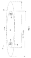
- FIG. 5 is a schematic view of a plurality of radio data nodes with at least one directional antenna 280, i.e., a DARDN 280 that may be used with monitoring system 200.
- DARDNs 280 define a second portion 285 of network 220.
- Each DARDN 280 is operatively coupled in communication with an opposing and adjacent DARDN 280.
- each DARDN 280 has a range of approximately 100 m (328 ft) to 175 m (574 ft) as indicated by range ellipses 290 such that an overlap region 295 is defined.
- ranges are associated with adjacent DARDNs 280 and may vary with other configurations that include adjacent OARDNs 265 (shown in FIG. 4 ).
- each DARDN 280 is a communication node, and more specifically, in the example embodiment, is a directional wSIM.
- each DARDN 280 is any directional wireless sensor interface device.
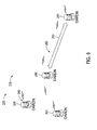
- FIG. 6 is a schematic view of OARDNs 265 and DARDNs 280 integrated in monitoring system 200.
- First portion 260 and second portion 285 of wireless mesh network 220 are coupled such that each OARDN 265 adjacent to a first DARDN 280 are operatively coupled in communication.
- first DARDN 280 and second DARDN 280 are operatively coupled in communication with each other.
- second DARDN 280 is operatively coupled in communication with additional OARDNs 265 (not shown in FIG. 6 ). Therefore, facility 208 (shown in FIG. 2 ) that includes regions with rugged landscapes that exclude use of OARDNs 265 may extend network 220 through those geographically rugged regions with use of DARDNs 280. Use of such DARDNs 280 also decreases costs and complexity of installation of network 220.
- FIG. 7 is a flow chart of an example method 300 of assembling network 220 (shown in FIG. 6 ).
- at least one computing device 105/210/215 (shown in FIGs. 1 , 2 , and 3 ) is provided 302.
- Programmed computer instructions compliant with IEEE standard 802.15.4 TM are installed 304 on at least a portion of computing device 105/210/215.
- network 220 is a low-rate wireless mesh network that uses the ZigBee ® specification., or alternatively, the WirelessHART TM standard based on the IEEE standard 802.15.4 TM .
- At least one omnidirectional antenna, i.e., OARDN 265 (shown in FIGs.
- DARDNs 280 (shown in FIGs. 5 and 6 ) and a plurality of directional antennas, or DARDNs 280 (shown in FIGs. 5 and 6 ) are provided 306. At least one of the OARDNs 265 and at least one of the plurality of DARDNs 280 are operatively coupled 308 to the computing device 105/210/215.
- the methods, systems, and apparatus described herein provide low cost transmission of monitoring data. Specifically, in contrast to known wireless mesh networks, the monitoring methods, systems, and apparatus described herein facilitate transmitting operational data associated with a facility to remote and/or difficult-to-access regions of the facility. More specifically, in contrast to known wireless mesh networks, the monitoring methods, systems, and apparatus described herein facilitate using transmission and receiving devices that have a low data rate and a low power usage.
- An example technical effect of the methods, systems, and apparatus described herein includes at least one of (a) enabling transmission and receipt of monitoring data in remote areas of a facility that would otherwise be inaccessible with omnidirectional antennas; (b) enabling the use of low power/low data rate devices in remote and/or difficult-to-access regions of a facility such that use of such low power devices for extended periods of time is facilitated, thereby increasing the reliability of such devices and decreasing a need for fully charged backup devices; and (c) decreasing the number of, and the associated costs of, additional omnidirectional antennas.
- wireless mesh networks and monitoring systems that facilitate enabling transmission and receipt of monitoring data in remote and/or difficult-to-access regions of a facility.
- the wireless mesh networks and monitoring systems described herein use directional antennas to facilitate extending such networks and monitoring systems through regions with rugged landscapes that exclude use of omnidirectional antennas.
- the wireless mesh networks and monitoring systems described herein use directional antennas with low power/low data rate networks and systems to replace a greater number of omnidirectional antennas, thereby facilitating a decrease of complexity and costs of installation and operation of such of wireless mesh networks and monitoring systems.
- Some embodiments involve the use of one or more electronic or computing devices.
- Such devices typically include a processor or controller, such as a general purpose central processing unit (CPU), a graphics processing unit (GPU), a microcontroller, a reduced instruction set computer (RISC) processor, an application specific integrated circuit (ASIC), a programmable logic circuit (PLC), and/or any other circuit or processor capable of executing the functions described herein.
- the methods described herein may be encoded as executable instructions embodied in a computer readable medium, including, without limitation, a storage device and/or a memory device. Such instructions, when executed by a processor, cause the processor to perform at least a portion of the methods described herein.
- the above represent examples only, and thus are not intended to limit in any way the definition and/or meaning of the term processor.
Landscapes
- Engineering & Computer Science (AREA)
- Computer Networks & Wireless Communication (AREA)
- Signal Processing (AREA)
- Mobile Radio Communication Systems (AREA)
- Arrangements For Transmission Of Measured Signals (AREA)
- Radio Relay Systems (AREA)
Applications Claiming Priority (1)
| Application Number | Priority Date | Filing Date | Title |
|---|---|---|---|
| US13/169,657 US20120326927A1 (en) | 2011-06-27 | 2011-06-27 | Apparatus and method for enhancing wireless mesh network communications |
Publications (1)
| Publication Number | Publication Date |
|---|---|
| EP2542016A2 true EP2542016A2 (fr) | 2013-01-02 |
Family
ID=46704450
Family Applications (1)
| Application Number | Title | Priority Date | Filing Date |
|---|---|---|---|
| EP12173248A Withdrawn EP2542016A2 (fr) | 2011-06-27 | 2012-06-22 | Appareil et procédé d'amélioration des communications de réseau maillé sans fil |
Country Status (4)
| Country | Link |
|---|---|
| US (1) | US20120326927A1 (fr) |
| EP (1) | EP2542016A2 (fr) |
| JP (1) | JP2013013076A (fr) |
| CN (1) | CN102857935A (fr) |
Families Citing this family (8)
| Publication number | Priority date | Publication date | Assignee | Title |
|---|---|---|---|---|
| US9426716B2 (en) * | 2013-06-28 | 2016-08-23 | Cisco Technology, Inc. | Optimizing communication for mesh routing protocols using directional beam forming |
| US9860782B2 (en) | 2015-11-05 | 2018-01-02 | International Business Machines Corporation | Routing of signals in a mesh network to reduce burden on intermediary nodes |
| US10338193B2 (en) * | 2016-10-07 | 2019-07-02 | Marko Beko | Apparatus and method for RSS/AoA target 3-D localization in wireless networks |
| US11503479B2 (en) * | 2019-05-10 | 2022-11-15 | Parallel Wireless, Inc. | Backhaul dynamic link distance |
| JP7336301B2 (ja) * | 2019-07-31 | 2023-08-31 | 国際衛生株式会社 | 倉庫関連情報管理システム、倉庫関連情報管理システムの制御方法、倉庫関連情報管理プログラム |
| US12511410B1 (en) | 2025-03-06 | 2025-12-30 | Qdacomm Llc | Physical layer security |
| US12395128B1 (en) | 2025-03-06 | 2025-08-19 | Qdacomm Llc | Decomposition of signals into a sum of truncated fourier series |
| US12401997B1 (en) | 2025-03-06 | 2025-08-26 | Qdacomm Llc | Physical layer security |
Family Cites Families (7)
| Publication number | Priority date | Publication date | Assignee | Title |
|---|---|---|---|---|
| US7151938B2 (en) * | 2002-04-15 | 2006-12-19 | America Online, Inc. | Dynamically managing and reconfiguring wireless mesh networks |
| US7664054B2 (en) * | 2005-03-28 | 2010-02-16 | Microsoft Corporation | Neighbor location discovery with directional antennas in a mesh network |
| US20070115116A1 (en) * | 2005-11-21 | 2007-05-24 | General Electric Company | System and method for wireless communication of facility data |
| CA2643254C (fr) * | 2006-03-14 | 2014-02-11 | Jamie Hackett | Module recepteur-controleur radio frequence longue portee et systeme de controle sans fil comprenant le meme |
| US8112381B2 (en) * | 2007-11-02 | 2012-02-07 | Siemens Corporation | Multivariate analysis of wireless sensor network data for machine condition monitoring |
| WO2009132425A1 (fr) * | 2008-04-29 | 2009-11-05 | Jamie Hackett | Système de commande sans fil utilisant des émetteurs-récepteurs à double modulation à puissance variable |
| US8326322B2 (en) * | 2008-11-28 | 2012-12-04 | Canon Kabushiki Kaisha | Methods for managing communications of a wireless communications network, corresponding storage means and devices |
-
2011
- 2011-06-27 US US13/169,657 patent/US20120326927A1/en not_active Abandoned
-
2012
- 2012-06-22 EP EP12173248A patent/EP2542016A2/fr not_active Withdrawn
- 2012-06-26 JP JP2012142550A patent/JP2013013076A/ja active Pending
- 2012-06-27 CN CN2012103387089A patent/CN102857935A/zh active Pending
Non-Patent Citations (1)
| Title |
|---|
| None |
Also Published As
| Publication number | Publication date |
|---|---|
| US20120326927A1 (en) | 2012-12-27 |
| CN102857935A (zh) | 2013-01-02 |
| JP2013013076A (ja) | 2013-01-17 |
Similar Documents
| Publication | Publication Date | Title |
|---|---|---|
| EP2542016A2 (fr) | Appareil et procédé d'amélioration des communications de réseau maillé sans fil | |
| Zakaria et al. | Development of a smart sensing unit for LoRaWAN-based IoT flood monitoring and warning system in catchment areas | |
| Civerchia et al. | Industrial Internet of Things monitoring solution for advanced predictive maintenance applications | |
| Dohare et al. | Wireless communication and environment monitoring in underground coal mines–review | |
| EP2941708B1 (fr) | Système et procédé de développement, de déploiement et d'implémentation d'applications informatiques de système d'alimentation | |
| CN202394086U (zh) | 过程控制系统 | |
| Catenazzo et al. | On the use of wireless sensor networks in preventative maintenance for industry 4.0 | |
| CN103065210A (zh) | 过程控制环境中的资产跟踪 | |
| CN111174905B (zh) | 低功耗物联网振动异常检测装置及其检测方法 | |
| US9668196B2 (en) | Network administrator interface systems and methods for monitoring industrial wireless, self-organizing mesh communication networks | |
| Gliga et al. | A survey of wireless communication technologies for an IoT-connected wind farm | |
| US20130214970A1 (en) | Apparatus and method for enhancing wireless mesh network communications | |
| Bhavanam et al. | LoRa Sense: Sensing and Optimization of LoRa Link Behavior Using Path-Loss Models in Open-Cast Mines. | |
| EP2725842A2 (fr) | Appareil et procédé de communications de réseau maillé sans fil | |
| EP2542017A2 (fr) | Appareil et procédé d'amélioration des communications de réseau maillé sans fil | |
| Xiang-li et al. | A remote manufacturing monitoring system based on the Internet of Things | |
| Ahmed et al. | Case study: Application of wireless condition based monitoring by applying machine learning models | |
| CN210927996U (zh) | 基于自组网的设备监测管理平台 | |
| CN111010309A (zh) | 基于自组网的设备监测管理方法、电子设备及存储介质 | |
| Śliwa et al. | The Latest Advances in Wireless Communication in Aviation, Wind Turbines and Bridges. Inventions 2022; 7 (18) | |
| Kovalev et al. | Innovative, semi-permanent sensors in the era of Industry 4.0: Technological solutions for efficient monitoring and automation | |
| Fuhr | Wireless sensor networks for the monitoring and control of nuclear power plants | |
| Ahmed et al. | Pilot Deployment of IIoT-SCADA by Leveraging Low Power Communication Technologies, Sensors, and Legacy Scada Controllers | |
| Ranaware et al. | Wireless Sensor Network for Performance Monitoring of Electrical Machine | |
| Usman et al. | Low-Cost LoRaWAN Solution for Groundwater Monitoring in Peatlands |
Legal Events
| Date | Code | Title | Description |
|---|---|---|---|
| PUAI | Public reference made under article 153(3) epc to a published international application that has entered the european phase |
Free format text: ORIGINAL CODE: 0009012 |
|
| AK | Designated contracting states |
Kind code of ref document: A2 Designated state(s): AL AT BE BG CH CY CZ DE DK EE ES FI FR GB GR HR HU IE IS IT LI LT LU LV MC MK MT NL NO PL PT RO RS SE SI SK SM TR |
|
| AX | Request for extension of the european patent |
Extension state: BA ME |
|
| STAA | Information on the status of an ep patent application or granted ep patent |
Free format text: STATUS: THE APPLICATION IS DEEMED TO BE WITHDRAWN |
|
| 18D | Application deemed to be withdrawn |
Effective date: 20150106 |