EP2541687B1 - Cable connection assembly - Google Patents
Cable connection assembly Download PDFInfo
- Publication number
- EP2541687B1 EP2541687B1 EP12185133.1A EP12185133A EP2541687B1 EP 2541687 B1 EP2541687 B1 EP 2541687B1 EP 12185133 A EP12185133 A EP 12185133A EP 2541687 B1 EP2541687 B1 EP 2541687B1
- Authority
- EP
- European Patent Office
- Prior art keywords
- cable
- main body
- seal
- connection assembly
- cable connection
- Prior art date
- Legal status (The legal status is an assumption and is not a legal conclusion. Google has not performed a legal analysis and makes no representation as to the accuracy of the status listed.)
- Not-in-force
Links
Images


Classifications
-
- H—ELECTRICITY
- H01—ELECTRIC ELEMENTS
- H01R—ELECTRICALLY-CONDUCTIVE CONNECTIONS; STRUCTURAL ASSOCIATIONS OF A PLURALITY OF MUTUALLY-INSULATED ELECTRICAL CONNECTING ELEMENTS; COUPLING DEVICES; CURRENT COLLECTORS
- H01R4/00—Electrically-conductive connections between two or more conductive members in direct contact, i.e. touching one another; Means for effecting or maintaining such contact; Electrically-conductive connections having two or more spaced connecting locations for conductors and using contact members penetrating insulation
- H01R4/58—Electrically-conductive connections between two or more conductive members in direct contact, i.e. touching one another; Means for effecting or maintaining such contact; Electrically-conductive connections having two or more spaced connecting locations for conductors and using contact members penetrating insulation characterised by the form or material of the contacting members
- H01R4/60—Connections between or with tubular conductors
-
- H—ELECTRICITY
- H01—ELECTRIC ELEMENTS
- H01R—ELECTRICALLY-CONDUCTIVE CONNECTIONS; STRUCTURAL ASSOCIATIONS OF A PLURALITY OF MUTUALLY-INSULATED ELECTRICAL CONNECTING ELEMENTS; COUPLING DEVICES; CURRENT COLLECTORS
- H01R13/00—Details of coupling devices of the kinds covered by groups H01R12/70 or H01R24/00 - H01R33/00
- H01R13/46—Bases; Cases
- H01R13/52—Dustproof, splashproof, drip-proof, waterproof, or flameproof cases
- H01R13/5216—Dustproof, splashproof, drip-proof, waterproof, or flameproof cases characterised by the sealing material, e.g. gels or resins
-
- H—ELECTRICITY
- H01—ELECTRIC ELEMENTS
- H01B—CABLES; CONDUCTORS; INSULATORS; SELECTION OF MATERIALS FOR THEIR CONDUCTIVE, INSULATING OR DIELECTRIC PROPERTIES
- H01B7/00—Insulated conductors or cables characterised by their form
- H01B7/17—Protection against damage caused by external factors, e.g. sheaths or armouring
- H01B7/28—Protection against damage caused by moisture, corrosion, chemical attack or weather
- H01B7/282—Preventing penetration of fluid, e.g. water or humidity, into conductor or cable
- H01B7/285—Preventing penetration of fluid, e.g. water or humidity, into conductor or cable by completely or partially filling interstices in the cable
-
- H—ELECTRICITY
- H01—ELECTRIC ELEMENTS
- H01R—ELECTRICALLY-CONDUCTIVE CONNECTIONS; STRUCTURAL ASSOCIATIONS OF A PLURALITY OF MUTUALLY-INSULATED ELECTRICAL CONNECTING ELEMENTS; COUPLING DEVICES; CURRENT COLLECTORS
- H01R13/00—Details of coupling devices of the kinds covered by groups H01R12/70 or H01R24/00 - H01R33/00
- H01R13/46—Bases; Cases
- H01R13/52—Dustproof, splashproof, drip-proof, waterproof, or flameproof cases
- H01R13/5202—Sealing means between parts of housing or between housing part and a wall, e.g. sealing rings
-
- H—ELECTRICITY
- H01—ELECTRIC ELEMENTS
- H01R—ELECTRICALLY-CONDUCTIVE CONNECTIONS; STRUCTURAL ASSOCIATIONS OF A PLURALITY OF MUTUALLY-INSULATED ELECTRICAL CONNECTING ELEMENTS; COUPLING DEVICES; CURRENT COLLECTORS
- H01R13/00—Details of coupling devices of the kinds covered by groups H01R12/70 or H01R24/00 - H01R33/00
- H01R13/46—Bases; Cases
- H01R13/52—Dustproof, splashproof, drip-proof, waterproof, or flameproof cases
- H01R13/5205—Sealing means between cable and housing, e.g. grommet
-
- H—ELECTRICITY
- H01—ELECTRIC ELEMENTS
- H01R—ELECTRICALLY-CONDUCTIVE CONNECTIONS; STRUCTURAL ASSOCIATIONS OF A PLURALITY OF MUTUALLY-INSULATED ELECTRICAL CONNECTING ELEMENTS; COUPLING DEVICES; CURRENT COLLECTORS
- H01R13/00—Details of coupling devices of the kinds covered by groups H01R12/70 or H01R24/00 - H01R33/00
- H01R13/46—Bases; Cases
- H01R13/52—Dustproof, splashproof, drip-proof, waterproof, or flameproof cases
- H01R13/521—Sealing between contact members and housing, e.g. sealing insert
-
- H—ELECTRICITY
- H01—ELECTRIC ELEMENTS
- H01R—ELECTRICALLY-CONDUCTIVE CONNECTIONS; STRUCTURAL ASSOCIATIONS OF A PLURALITY OF MUTUALLY-INSULATED ELECTRICAL CONNECTING ELEMENTS; COUPLING DEVICES; CURRENT COLLECTORS
- H01R4/00—Electrically-conductive connections between two or more conductive members in direct contact, i.e. touching one another; Means for effecting or maintaining such contact; Electrically-conductive connections having two or more spaced connecting locations for conductors and using contact members penetrating insulation
- H01R4/70—Insulation of connections
-
- H—ELECTRICITY
- H02—GENERATION; CONVERSION OR DISTRIBUTION OF ELECTRIC POWER
- H02G—INSTALLATION OF ELECTRIC CABLES OR LINES, OR OF COMBINED OPTICAL AND ELECTRIC CABLES OR LINES
- H02G15/00—Cable fittings
- H02G15/02—Cable terminations
- H02G15/04—Cable-end sealings
- H02G15/043—Cable-end sealings with end caps, e.g. sleeve closed at one end
- H02G15/046—Cable-end sealings with end caps, e.g. sleeve closed at one end with bores or protruding portions allowing passage of cable conductors
-
- H—ELECTRICITY
- H02—GENERATION; CONVERSION OR DISTRIBUTION OF ELECTRIC POWER
- H02G—INSTALLATION OF ELECTRIC CABLES OR LINES, OR OF COMBINED OPTICAL AND ELECTRIC CABLES OR LINES
- H02G15/00—Cable fittings
- H02G15/02—Cable terminations
- H02G15/06—Cable terminating boxes, frames or other structures
-
- H—ELECTRICITY
- H02—GENERATION; CONVERSION OR DISTRIBUTION OF ELECTRIC POWER
- H02G—INSTALLATION OF ELECTRIC CABLES OR LINES, OR OF COMBINED OPTICAL AND ELECTRIC CABLES OR LINES
- H02G15/00—Cable fittings
- H02G15/20—Cable fittings for cables filled with or surrounded by gas or oil
- H02G15/22—Cable terminations
- H02G15/23—Cable-end sealings
-
- Y—GENERAL TAGGING OF NEW TECHNOLOGICAL DEVELOPMENTS; GENERAL TAGGING OF CROSS-SECTIONAL TECHNOLOGIES SPANNING OVER SEVERAL SECTIONS OF THE IPC; TECHNICAL SUBJECTS COVERED BY FORMER USPC CROSS-REFERENCE ART COLLECTIONS [XRACs] AND DIGESTS
- Y02—TECHNOLOGIES OR APPLICATIONS FOR MITIGATION OR ADAPTATION AGAINST CLIMATE CHANGE
- Y02A—TECHNOLOGIES FOR ADAPTATION TO CLIMATE CHANGE
- Y02A30/00—Adapting or protecting infrastructure or their operation
- Y02A30/14—Extreme weather resilient electric power supply systems, e.g. strengthening power lines or underground power cables
Definitions
- the illustrated embodiments of the present invention generally relate to cable connection assemblies, and more specifically, to cable connection assemblies for connecting a cable to an apparatus while permitting a fluid to be injected into the cable.
- Typical cables include a conductor, such as a number of copper or aluminum strands, surrounded by an insulation layer.
- a conductor such as a number of copper or aluminum strands
- the life span of a cable is shortened when water enters the cable and forms micro-voids in the insulation layer. These micro-voids spread throughout the insulation layer in a tree like shape, collections of which are sometimes referred to as water trees.
- Water trees are known to form in the insulation layer of electrical cables when voltage is applied to the cable in the presence of water and ions. As water trees grow, they compromise the dielectric properties of the insulation layer until failure occurs. Many large water trees initiate at the site of an imperfection or a contaminant, but contamination is not a necessary condition for water trees to propagate.
- Water tree growth can be eliminated or retarded by removing or minimizing the water or ions, or by reducing the voltage stress.
- Another approach requires the injection of a dielectric enhancement fluid into interstices located between the strands of the cables.
- injecting the dielectric enhancement fluid into the cable is difficult, especially if the cable is to remain in service during treatment. Accordingly, there exists a need for a device which permits a cable to be injected with restorative fluids, such as dielectric enhancement fluids, while permitting the cable to remain in use.
- an electrical connector comprising an outer body member including an inner cylinder portion, and a central conductive contact member which is adapted to have a piston-ring assembly secured thereto by means of a snap-ring.
- a sealing washer and the piston-ring assembly form, between them, an expansible chamber bounded by the inner wall of the cylinder and the main body portion of the contact member.
- restorative fluids such as dielectric enhancement fluids
- the cable connection assembly includes a main body defining an inner cavity adapted to receive a pressurized fluid and receive at least a portion of the cable therein.
- the cable connection assembly also includes an attachment mechanism adapted to couple the main body to the cable and a seal assembly adapted to sealingly couple the main body to the apparatus.
- the cable connection assembly also includes an inlet port passing through the main body for permitting the pressurized fluid to be injected into the inner cavity.
- the cable connection assembly includes a main body defining an inner cavity adapted to receive a pressurized fluid and receive at least a portion of the cable therein and a threaded portion disposed on a first end of the main body for coupling the main body to the cable.
- the cable connection assembly also includes a seal disposed on the second end of the main body for sealing the main body to the apparatus and an inlet port. The inlet port passes through the main body for permitting the pressurized fluid to be injected into the inner cavity of the main body.
- the cable connection assembly further includes a fastening mechanism disposed on a second end of the main body for coupling the main body to the apparatus.
- the cable connection assembly includes a main body defining an inner cavity adapted to receive a pressurized fluid and receive at least a portion of the cable.
- the cable connection assembly also includes a coupling assembly for coupling a first end of the main body to the cable and a seal assembly for sealing a second end of the main body to the apparatus.
- the cable connection assembly further includes an inlet port passing through the main body for permitting the pressurized fluid to be injected into the inner cavity of the main body and a sealing member.
- the sealing member is coupled to the main body. The sealing member is moveable between a closed position in which the sealing member impedes fluid from flowing through the inlet port and an open position in which the sealing member permits fluid to flow through the inlet port for receipt by the cable.
- the cable connection assembly 100 is adapted to couple a cable 102 to an apparatus 104 while permitting a fluid, one suitable example being a restorative fluid, such as a dielectric enhancement fluid, to be injected into the cable 102.
- a fluid one suitable example being a restorative fluid, such as a dielectric enhancement fluid
- the cable 102 may be any well known or to be developed cable, such as the cable 102 illustrated, having a plurality of conductors 103 surrounded by an insulation layer 120.
- the apparatus 104 may be any well known or to be developed component requiring connection to the cable 102, a few suitable examples being a termination connector, such as shown, for connecting the cable 102 to a device requiring to be in electrical communication with the cable 102, such as a junction box, transformer, etc.
- the cable connection assembly 100 includes a main body 106, an attachment mechanism 108, a fastening mechanism 109, a cable seal mechanism 110, a valve assembly 112, and an apparatus seal assembly 114.
- the main body 106 is suitably a cylindrically shaped structure, such as a collar, defining an inner cavity 116.
- the inner cavity 116 may be sized and shaped to receive at least a portion of the cable 102 and at least a portion of the apparatus 104. Further, the inner cavity 116 is adapted to receive the fluid mentioned above for treating the cable 102.
- the attachment mechanism 108 removably attaches a first end of the main body 106 to the cable 102.
- the attachment mechanism 108 includes a threaded portion 118 to engage corresponding threads 156 disposed on an insulation layer 120 of the cable 102.
- the attachment mechanism 108 is illustrated and described as utilizing threads to couple the cable connection assembly 100 to the cable 102, the attachment mechanism 108 may use various other means for coupling the cable connection assembly 100 to the cable 102, a few suitable examples being mechanical fasteners, self tapping threads, push on style barbed fittings, ferrule style connectors, quick-to-connect devices, and crimping devices that are capable of holding cable 102 in contact with main body 106.
- the fastening mechanism 109 removably attaches a second end of the main body 106 to the apparatus 104.
- the fastening mechanism 109 includes one or more fasteners 122, such as set screws, which pass radially through the main body 106.
- the fasteners 122 engage the apparatus 104, thereby mechanically and electrically coupling or locking the apparatus 104 to the main body 106.
- other types of fastening mechanisms 109 such as threads disposed on the main body 106, adhesives, quick-to-connect devices, crimping devices, self-locking retaining rings, welding, and chemical adhesives, are also within the scope of the present invention.
- the cable seal mechanism 110 is adapted to seal the main body 106 to the cable 102.
- the cable seal mechanism 110 includes a sealing surface 124 ( FIGURE 1 ) disposed on the main body 106 and a seal 126.
- the sealing surface 124 is an annularly shaped surface formed in the main body 106 and is adapted to sandwich the seal 126 against an end face 199 of the cable 102, thereby creating an end seal between the sealing surface 124 and the end face 199. Further, because of the threaded engagement between the cable 102 and the main body 106, the resulting attachment is more secure than existing designs.
- the end seal between the sealing surface 124 and the end face 199 is maintained during dynamic changes, such as thermal changes, in the insulation layer 120. Because the main body 106 is threadably connected to the insulation layer 120, any changes or movement of the insulation layer results in a corresponding movement of the main body 106. This maintains a secure end seal between the sealing surface 124 and the end face 199.
- the apparatus seal assembly 114 is adapted to seal the main body 106 to the apparatus 104.
- the apparatus seal assembly 114 includes an annular shaped sealing recess 132 or groove formed on the inner surface of the main body 106 and a seal 130.
- the sealing recess 132 is adapted to at least partially receive the seal 130 and sandwich the seal against the apparatus 104 to seal the main body 106 to the apparatus 104. It should be apparent that the main body 106 may be sealed to the apparatus 104 in any number of ways, including gaskets, a seal disposed against an endface of the apparatus 104, threading of the main body 106 upon the apparatus, liquid gasket compounds, etc.
- the valve assembly 112 includes a sealing member 132, an injection port 134, an inlet port 136, a valve seal assembly 138, and a locking assembly 140.
- the sealing member 132 of the illustrated embodiment is in the form of a sleeve which may be linearly moved in the direction of the longitudinal length of the cable connection assembly 100 as indicated by arrow 158 in FIGURE 2 .
- the sealing member 132 is adapted to slidingly receive the main body 106 within an inner passageway defined by the sealing member 132.
- the sealing member 132 includes the injection port 134.
- the injection port 134 is adapted to interface with a fluid injection source to permit a fluid to pass through the sealing member 132 and into the inner cavity 116 of the main body 106.
- the valve assembly 112 may include one or more inlet ports 136.
- the inlet ports 136 may pass through the main body 106 for permitting a fluid to pass through the main body 106 and into the inner cavity 116.
- the inlet ports 136 may pass through the main body 106 in a radial direction. In the illustrated embodiment, there are multiple inlet ports 136 spaced equidistant about the circumference of the main body 106. Although multiple inlet ports 136 are illustrated and described, it should be noted that a single inlet port 136 is also suitable for use with the present invention.
- the sealing member 132 is moveable relative to the main body 106.
- the sealing member 132 may be linearly moved between at least a closed position and an open position.
- the injection port 134 associated with the sealing member 132 is selectively positioned such that the fluid may flow through the injection port 134, through the inlet ports 136, and into the inner cavity 116.
- the injection port 134 associated with the sealing member 132 is aligned such that the injection port 134 is no longer in fluid communication with the inlet ports 136.
- fluid is impeded from flowing through the injection port 134 and into the inner cavity 116 via the inlet ports 136.
- the valve assembly 112 may further include a valve seal assembly 138.
- the valve seal assembly 138 includes a pair of seals 142 and 144 disposed on each side of the inlet ports 136.
- the seals 142 and 144 may be annular in shape and may circumferentially engage both the sealing member 132 and the main body 106, sealing the sealing member 132 to the main body 106.
- the seals 142 and 144 help define a fluid passageway 146 defined by the space between the seals 142 and 144, an inner surface of the sealing member 132, and an outer surface of the main body 106.
- the sealing member 132 may have a channel disposed on the inner surface of the sealing member 132 to increase the cross-sectional area of the fluid passageway 146.
- the fluid may pass circumferentially along the annular shaped fluid passageway 146 and enter the inner cavity 116 through the inlet ports 136.
- the locking assembly 140 may be used to lock the sealing member 132 of the valve assembly 112 in either the open position or the closed position.
- the locking assembly 140 may include a locking channel 148 disposed circumferentially about the outer surface of the main body 106.
- the locking channel 148 is sized and shape to receive a locking member 150, a few suitable examples being a snap ring or clip.
- the locking member 150 is sized and shaped to extend radially outward of the locking channel 148 so as to block movement of the sealing member 132 from the closed position depicted in FIGURE 2 , to the open position shown in FIGURE 1 .
- the locking member 150 is simply removed from the locking channel 148 as shown in FIGURE 1 , permitting the sealing member 132 to slide past the locking channel 148.
- the locking assembly 140 may include a locking flange 152.
- the locking flange 152 may extend radially outward of the outer surface of the main body 106.
- the locking flange 152 may be sized and shaped to be a limit stop for a locking member 154, a few suitable examples being a wide snap ring or wide clip.
- the locking member 154 is sized and shaped to abut the locking flange 152 and the sealing member 132 when the sealing member 132 is in the open position as shown in FIGURE 1 .
- the sealing member 132 is impeded from moving back towards the locking flange 152 to the closed position depicted in FIGURE 2 .
- the locking member 154 is simply removed as shown in FIGURE 2 , permitting the sealing member 132 to slide toward the locking flange 152.
- locking flange 152 is illustrated and described as being used in locking the sealing member 132 in the open position, and the locking channel 148 used in locking the sealing member 132 in the closed position, it should be noted that in other embodiments, a locking flange may be used in locking the sealing member 132 in the closed position, and a locking channel may be used to lock the sealing member 132 in the open position.
- the locking assembly 140 is shown and illustrated with specific structures for locking the sealing member 132 in either the open position or the closed position, other structures may be used to hold the sealing member 132 in either the open or closed position, a few suitable examples being ball and detent systems, twist-to-lock structures, bayonet style locking mechanisms, fasteners, etc.
- the insulation layer 120 of the cable 102 may be cut back exposing the conductors 103.
- the insulation layer 120 may then be threaded to form external threads 156 sized and shaped to interface with the threaded portion 118 of the main body 106.
- the main body 106 is then threaded onto the cable 106.
- the seal 126 is sandwiched between the sealing surface 124 and the endface 199 providing a fluid seal therebetween, in addition to the seal caused by the interfacing of threads 156 of the insulation layer 120 with the threaded portion 118 of the main body 106.
- the distal end of the apparatus 104 may then be slid within the inner cavity 116 of the main body 106 with the conductors 103 of the cable 102 extending within the apparatus 104.
- the apparatus 104 may then be crimped upon the conductors 103 to retain the apparatus 104 to the cable 102.
- Seal 130 seals the main body 106 to the apparatus 104.
- Fasteners 122 are then driven to engage the apparatus 104 to mechanically couple the cable connection assembly 100 to the apparatus 104.
- Locking member 154 is placed in position to retain the sealing member 132 in the open position.
- a restorative fluid is injected through the injection port 134 to pass through the fluid passageway 146 and enter the inner cavity 116 through one or more of the inlet ports 136.
- the sealing member 132 may be placed in the closed position by removing the locking member 154 and sliding the sealing member 132 in the direction of arrow 158. Locking member 150 may then be inserted in locking channel 148 to retain the sealing member 132 in the closed position.
- the injection port 134 is out of alignment with the fluid passageway 146, and the inner cavity 116 is now a sealed pressure vessel able to hold a fluid under pressure within the cavity.
- FIGURES 4 and 5 an alternate embodiment of a cable connection assembly 200 formed in accordance with the present invention is illustrated.
- the cable connection assembly 200 is substantially similar in construction and operation to the cable connection assembly 100 of FIGURES 1-3 described above. Therefore, for the sake of brevity, this detailed description will focus upon the aspects of the cable connection assembly 200 of FIGURES 4 and 5 which depart from the previously described embodiment, which is the construction and operation of the valve assembly.
- valve assembly 212 of this embodiment differs from the valve assembly of the previously described embodiment in that sealing member 232 is rotatable between the open position shown in FIGURE 4 and the closed position shown in FIGURE 5 , rather than linearly moveable between the open and closed positions as shown and described for the previous embodiment.
- valve assembly 212 is rotated into the open position by rotating the sealing member 232 about the longitudinal axis of the cable connection assembly 200 and about the outer surface of the main body 206.
- the sealing member 232 is in the open position when the injection port 234 of the sealing member 232 is aligned with one of the inlet ports 236 of the main body 206 as shown in FIGURE 4 .
- a seal 260 may be used to seal the inlet port 236 to the injection port 234.
- the valve assembly 212 is rotated to the closed position by rotating the sealing member 232 about the longitudinal axis of the cable connection assembly 200 and about the outer surface of the main body 206.
- the sealing member 232 is in the closed position when the injection port 234 of the sealing member 232 is not aligned with any one of the inlet ports 236 of the main body 206 as shown in FIGURE 5 .
- the seal 260 seals against the sealing member 232, thereby forming the inner cavity 216 into a pressure vessel able to hold a fluid under pressure.
- the sealing member 232 is impeded from moving linearly along the length of the cable connection assembly 200 via the locking flange 252 and the locking member 250 disposed on each side of the sealing member.
- FIGURES 6 and 7 an alternate embodiment of a cable connection assembly 300 formed in accordance with the present invention is illustrated.
- the cable connection assembly 300 is substantially similar in construction and operation to the cable connection assembly 100 of FIGURES 1-3 described above. Therefore, for the sake of brevity, this detailed description will focus upon the aspects of the cable connection assembly 300 of FIGURES 6 and 7 which depart from the previously described embodiments, which is the construction and operation of the valve assembly.
- valve assembly 312 of this embodiment differs from the valve assembly of the previously described embodiment in that sealing member 332 is linearly moveable, preferably in a radial direction 362, between the open position shown in FIGURE 6 and the closed position shown in FIGURE 7 , rather than linearly moveable in a longitudinal direction between the open and closed positions are shown and described for the embodiment of FIGURES 1-3 .
- valve assembly 312 is moved into the open position by linearly moving the sealing member 332 in the direction of a radial oriented axis 362 oriented perpendicular to the longitudinal axis of the cable connection assembly 300. More specifically, the valve assembly 312 of this embodiment may act as a check valve permitting flow into the inner cavity 316, unless held open.
- the valve assembly 312 may include a valve body 364, a biasing member 366, a valve seat 368, and a retaining assembly 370.
- the valve body 364 may house the sealing member 332, biasing member 366, and the retaining assembly 370.
- the biasing member 366 which may be a valve spring, biases the sealing member 332 into sealing engagement with the valve seat 368, thereby sealing the injection port 334, preventing the entrance or exit of fluid into the inner cavity 316.
- the retaining assembly 370 retains the biasing member 366 in the valve body 364.
- the retaining assembly 370 includes a base plate 372 and a retaining clip 374. The base plate 372 is retained in the valve body 364 via the retaining clip 374 and supports/retains the biasing member 366 in the valve body 364.
- the biasing force applied upon the sealing member 332 by the biasing member 366 is overcome. Once overcome, the sealing member 332 moves away from the valve seat 368, permitting the fluid to enter the fluid injection port 334, travel through the valve body 364, and out the inlet port 336 in the base plate 372 to enter the inner cavity 316 as shown in FIGURE 6 .
- the biasing force applied by the biasing member 366 is no longer overcome, thereby resulting in the sealing member 332 moving linearly outward in a radial direction to sealingly engage the valve seat 368, thereby forming the inner cavity 316 into a pressure vessel able to hold a fluid under pressure as shown in FIGURE 7 .
- the sealing member 332 is impeded from moving from the closed position by the biasing member 366 until once again a fluid is injected through the injection port 334 and the biasing force of the biasing member 366 overcome.
Description
- The illustrated embodiments of the present invention generally relate to cable connection assemblies, and more specifically, to cable connection assemblies for connecting a cable to an apparatus while permitting a fluid to be injected into the cable.
- Typical cables include a conductor, such as a number of copper or aluminum strands, surrounded by an insulation layer. In some instances, the life span of a cable is shortened when water enters the cable and forms micro-voids in the insulation layer. These micro-voids spread throughout the insulation layer in a tree like shape, collections of which are sometimes referred to as water trees.
- Water trees are known to form in the insulation layer of electrical cables when voltage is applied to the cable in the presence of water and ions. As water trees grow, they compromise the dielectric properties of the insulation layer until failure occurs. Many large water trees initiate at the site of an imperfection or a contaminant, but contamination is not a necessary condition for water trees to propagate.
- Water tree growth can be eliminated or retarded by removing or minimizing the water or ions, or by reducing the voltage stress. Another approach requires the injection of a dielectric enhancement fluid into interstices located between the strands of the cables. However, injecting the dielectric enhancement fluid into the cable is difficult, especially if the cable is to remain in service during treatment. Accordingly, there exists a need for a device which permits a cable to be injected with restorative fluids, such as dielectric enhancement fluids, while permitting the cable to remain in use.
- In
US 3,444, 507 A , an electrical connector is disclosed. The connector comprises an outer body member including an inner cylinder portion, and a central conductive contact member which is adapted to have a piston-ring assembly secured thereto by means of a snap-ring. When the elements of the connector have been assembled together, a sealing washer and the piston-ring assembly form, between them, an expansible chamber bounded by the inner wall of the cylinder and the main body portion of the contact member. By means of an inlet passage, it is possible to introduce flowable fluid material into the expansible chamber. Introduction of the fluid, under pressure, will displace the contact element relative to the body member. - It is an objective of the present invention to provide a device which permits a cable to be injected with restorative fluids, such as dielectric enhancement fluids, while permitting the cable to remain in use. This problem is solved by the combination of a cable and a cable connection assembly of claim 1. Preferred embodiments are described in the depending claims.
- One embodiment of a cable connection assembly formed in accordance with the present invention for coupling a cable to an apparatus is disclosed. The cable connection assembly includes a main body defining an inner cavity adapted to receive a pressurized fluid and receive at least a portion of the cable therein. The cable connection assembly also includes an attachment mechanism adapted to couple the main body to the cable and a seal assembly adapted to sealingly couple the main body to the apparatus. The cable connection assembly also includes an inlet port passing through the main body for permitting the pressurized fluid to be injected into the inner cavity.
- An alternate embodiment of a cable connection assembly formed in accordance with the present invention for coupling a cable to an apparatus is disclosed. The cable connection assembly includes a main body defining an inner cavity adapted to receive a pressurized fluid and receive at least a portion of the cable therein and a threaded portion disposed on a first end of the main body for coupling the main body to the cable. The cable connection assembly also includes a seal disposed on the second end of the main body for sealing the main body to the apparatus and an inlet port. The inlet port passes through the main body for permitting the pressurized fluid to be injected into the inner cavity of the main body. The cable connection assembly further includes a fastening mechanism disposed on a second end of the main body for coupling the main body to the apparatus.
- Still another alternate embodiment of a cable connection assembly formed in accordance with the present invention for coupling a cable to an apparatus is disclosed. The cable connection assembly includes a main body defining an inner cavity adapted to receive a pressurized fluid and receive at least a portion of the cable. The cable connection assembly also includes a coupling assembly for coupling a first end of the main body to the cable and a seal assembly for sealing a second end of the main body to the apparatus. The cable connection assembly further includes an inlet port passing through the main body for permitting the pressurized fluid to be injected into the inner cavity of the main body and a sealing member. The sealing member is coupled to the main body. The sealing member is moveable between a closed position in which the sealing member impedes fluid from flowing through the inlet port and an open position in which the sealing member permits fluid to flow through the inlet port for receipt by the cable.
- The foregoing aspects and many of the attendant advantages of this invention will become better understood by reference to the following detailed description, when taken in conjunction with the accompanying drawings, wherein:
-
FIGURE 1 is a perspective, partial cut-away view of one embodiment of a cable connection assembly formed in accordance with the present invention, the cable connection assembly shown with a valve assembly of the cable connection assembly in an open position permitting fluid to enter the cable connection assembly through the valve assembly; -
FIGURE 2 is a perspective, partial cut-away view of the cable connection assembly ofFIGURE 1 , the cable connection assembly illustrated with the valve assembly in a closed position blocking fluid from exiting and/or entering the cable connection assembly through the valve assembly; -
FIGURE 3 , is a perspective, exploded view of the cable connection assembly ofFIGURE 1 ; -
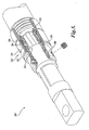
FIGURE 4 is a perspective, partial cut-away view of an alternate embodiment of a cable connection assembly formed in accordance with the present invention, the cable connection assembly shown with a valve assembly of the cable connection assembly in an open position permitting fluid to enter the cable connection assembly through the valve assembly; -
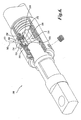
FIGURE 5 is a perspective, partial cut-away view of the cable connection assembly ofFIGURE 4 , the cable connection assembly illustrated with the valve assembly in a closed position blocking fluid from exiting the cable connection assembly through the valve assembly; -
FIGURE 6 is a perspective, partial cut-away view of still yet another embodiment of a cable connection assembly formed in accordance with the present invention, the cable connection assembly shown with a valve assembly of the cable connection assembly in an open position permitting fluid to enter the cable connection assembly through the valve assembly; and -
FIGURE 7 is a perspective, partial cut-away view of the cable connection assembly ofFIGURE 6 , the cable connection assembly illustrated with the valve assembly in a closed position blocking fluid from exiting the cable connection assembly through the valve assembly. - Referring to
FIGURES 1-3 , one embodiment of acable connection assembly 100 formed in accordance with the present invention is shown. Generally described, thecable connection assembly 100 is adapted to couple acable 102 to anapparatus 104 while permitting a fluid, one suitable example being a restorative fluid, such as a dielectric enhancement fluid, to be injected into thecable 102. Thecable 102 may be any well known or to be developed cable, such as thecable 102 illustrated, having a plurality ofconductors 103 surrounded by aninsulation layer 120. Theapparatus 104 may be any well known or to be developed component requiring connection to thecable 102, a few suitable examples being a termination connector, such as shown, for connecting thecable 102 to a device requiring to be in electrical communication with thecable 102, such as a junction box, transformer, etc. - Referring to
FIGURES 1 and3 , thecable connection assembly 100 includes amain body 106, anattachment mechanism 108, afastening mechanism 109, acable seal mechanism 110, avalve assembly 112, and anapparatus seal assembly 114. Themain body 106 is suitably a cylindrically shaped structure, such as a collar, defining aninner cavity 116. Theinner cavity 116 may be sized and shaped to receive at least a portion of thecable 102 and at least a portion of theapparatus 104. Further, theinner cavity 116 is adapted to receive the fluid mentioned above for treating thecable 102. - The
attachment mechanism 108 removably attaches a first end of themain body 106 to thecable 102. In the illustrated embodiment, theattachment mechanism 108 includes a threadedportion 118 to engagecorresponding threads 156 disposed on aninsulation layer 120 of thecable 102. Although theattachment mechanism 108 is illustrated and described as utilizing threads to couple thecable connection assembly 100 to thecable 102, theattachment mechanism 108 may use various other means for coupling thecable connection assembly 100 to thecable 102, a few suitable examples being mechanical fasteners, self tapping threads, push on style barbed fittings, ferrule style connectors, quick-to-connect devices, and crimping devices that are capable of holdingcable 102 in contact withmain body 106. - The
fastening mechanism 109 removably attaches a second end of themain body 106 to theapparatus 104. Thefastening mechanism 109 includes one ormore fasteners 122, such as set screws, which pass radially through themain body 106. Thefasteners 122 engage theapparatus 104, thereby mechanically and electrically coupling or locking theapparatus 104 to themain body 106. It should be apparent to one of ordinary skill that other types offastening mechanisms 109, such as threads disposed on themain body 106, adhesives, quick-to-connect devices, crimping devices, self-locking retaining rings, welding, and chemical adhesives, are also within the scope of the present invention. - The
cable seal mechanism 110 is adapted to seal themain body 106 to thecable 102. Thecable seal mechanism 110 includes a sealing surface 124 (FIGURE 1 ) disposed on themain body 106 and aseal 126. The sealing surface 124 is an annularly shaped surface formed in themain body 106 and is adapted to sandwich theseal 126 against anend face 199 of thecable 102, thereby creating an end seal between the sealing surface 124 and theend face 199. Further, because of the threaded engagement between thecable 102 and themain body 106, the resulting attachment is more secure than existing designs. - Specifically, the end seal between the sealing surface 124 and the
end face 199 is maintained during dynamic changes, such as thermal changes, in theinsulation layer 120. Because themain body 106 is threadably connected to theinsulation layer 120, any changes or movement of the insulation layer results in a corresponding movement of themain body 106. This maintains a secure end seal between the sealing surface 124 and theend face 199. - The
apparatus seal assembly 114 is adapted to seal themain body 106 to theapparatus 104. Theapparatus seal assembly 114 includes an annular shaped sealingrecess 132 or groove formed on the inner surface of themain body 106 and aseal 130. The sealingrecess 132 is adapted to at least partially receive theseal 130 and sandwich the seal against theapparatus 104 to seal themain body 106 to theapparatus 104. It should be apparent that themain body 106 may be sealed to theapparatus 104 in any number of ways, including gaskets, a seal disposed against an endface of theapparatus 104, threading of themain body 106 upon the apparatus, liquid gasket compounds, etc. - The
valve assembly 112 includes a sealingmember 132, aninjection port 134, aninlet port 136, avalve seal assembly 138, and a lockingassembly 140. The sealingmember 132 of the illustrated embodiment is in the form of a sleeve which may be linearly moved in the direction of the longitudinal length of thecable connection assembly 100 as indicated byarrow 158 inFIGURE 2 . The sealingmember 132 is adapted to slidingly receive themain body 106 within an inner passageway defined by the sealingmember 132. The sealingmember 132 includes theinjection port 134. Theinjection port 134 is adapted to interface with a fluid injection source to permit a fluid to pass through the sealingmember 132 and into theinner cavity 116 of themain body 106. - The
valve assembly 112 may include one ormore inlet ports 136. Theinlet ports 136 may pass through themain body 106 for permitting a fluid to pass through themain body 106 and into theinner cavity 116. Theinlet ports 136 may pass through themain body 106 in a radial direction. In the illustrated embodiment, there aremultiple inlet ports 136 spaced equidistant about the circumference of themain body 106. Althoughmultiple inlet ports 136 are illustrated and described, it should be noted that asingle inlet port 136 is also suitable for use with the present invention. - Returning the focus to the sealing
member 132, as noted above, the sealingmember 132 is moveable relative to themain body 106. The sealingmember 132 may be linearly moved between at least a closed position and an open position. In the open position shown inFIGURE 1 , theinjection port 134 associated with the sealingmember 132 is selectively positioned such that the fluid may flow through theinjection port 134, through theinlet ports 136, and into theinner cavity 116. In the closed position shown inFIGURE 2 , theinjection port 134 associated with the sealingmember 132 is aligned such that theinjection port 134 is no longer in fluid communication with theinlet ports 136. Thus, in the closed position, fluid is impeded from flowing through theinjection port 134 and into theinner cavity 116 via theinlet ports 136. - The
valve assembly 112 may further include avalve seal assembly 138. In the illustrated embodiment, thevalve seal assembly 138 includes a pair ofseals inlet ports 136. Theseals member 132 and themain body 106, sealing the sealingmember 132 to themain body 106. Theseals fluid passageway 146 defined by the space between theseals member 132, and an outer surface of themain body 106. As best shown inFIGURE 2 , the sealingmember 132 may have a channel disposed on the inner surface of the sealingmember 132 to increase the cross-sectional area of thefluid passageway 146. When a fluid is injected in theinjection port 134, the fluid may pass circumferentially along the annular shapedfluid passageway 146 and enter theinner cavity 116 through theinlet ports 136. - The locking
assembly 140 may be used to lock the sealingmember 132 of thevalve assembly 112 in either the open position or the closed position. For instance, the lockingassembly 140 may include a lockingchannel 148 disposed circumferentially about the outer surface of themain body 106. The lockingchannel 148 is sized and shape to receive a lockingmember 150, a few suitable examples being a snap ring or clip. The lockingmember 150 is sized and shaped to extend radially outward of the lockingchannel 148 so as to block movement of the sealingmember 132 from the closed position depicted inFIGURE 2 , to the open position shown inFIGURE 1 . To transition the sealingmember 132 from the closed position to the open position, the lockingmember 150 is simply removed from the lockingchannel 148 as shown inFIGURE 1 , permitting the sealingmember 132 to slide past the lockingchannel 148. - The locking
assembly 140 may include a lockingflange 152. The lockingflange 152 may extend radially outward of the outer surface of themain body 106. The lockingflange 152 may be sized and shaped to be a limit stop for a lockingmember 154, a few suitable examples being a wide snap ring or wide clip. The lockingmember 154 is sized and shaped to abut the lockingflange 152 and the sealingmember 132 when the sealingmember 132 is in the open position as shown inFIGURE 1 . When the lockingmember 154 is in place, the sealingmember 132 is impeded from moving back towards the lockingflange 152 to the closed position depicted inFIGURE 2 . To transition the sealingmember 132 from the open position to the closed position, the lockingmember 154 is simply removed as shown inFIGURE 2 , permitting the sealingmember 132 to slide toward the lockingflange 152. - Although the locking
flange 152 is illustrated and described as being used in locking the sealingmember 132 in the open position, and the lockingchannel 148 used in locking the sealingmember 132 in the closed position, it should be noted that in other embodiments, a locking flange may be used in locking the sealingmember 132 in the closed position, and a locking channel may be used to lock the sealingmember 132 in the open position. Further, it should also be noted, although the lockingassembly 140 is shown and illustrated with specific structures for locking the sealingmember 132 in either the open position or the closed position, other structures may be used to hold the sealingmember 132 in either the open or closed position, a few suitable examples being ball and detent systems, twist-to-lock structures, bayonet style locking mechanisms, fasteners, etc. - In light of the above description of the components of the
cable connection assembly 100, the operation of thecable connection assembly 100 will now be described. Referring toFIGURE 1 , prior to installation, theinsulation layer 120 of thecable 102 may be cut back exposing theconductors 103. Theinsulation layer 120 may then be threaded to formexternal threads 156 sized and shaped to interface with the threadedportion 118 of themain body 106. Themain body 106 is then threaded onto thecable 106. Theseal 126 is sandwiched between the sealing surface 124 and theendface 199 providing a fluid seal therebetween, in addition to the seal caused by the interfacing ofthreads 156 of theinsulation layer 120 with the threadedportion 118 of themain body 106. - The distal end of the
apparatus 104 may then be slid within theinner cavity 116 of themain body 106 with theconductors 103 of thecable 102 extending within theapparatus 104. Theapparatus 104 may then be crimped upon theconductors 103 to retain theapparatus 104 to thecable 102. Seal 130 seals themain body 106 to theapparatus 104.Fasteners 122 are then driven to engage theapparatus 104 to mechanically couple thecable connection assembly 100 to theapparatus 104. Lockingmember 154 is placed in position to retain the sealingmember 132 in the open position. A restorative fluid is injected through theinjection port 134 to pass through thefluid passageway 146 and enter theinner cavity 116 through one or more of theinlet ports 136. - Referring to
FIGURE 2 , the sealingmember 132 may be placed in the closed position by removing the lockingmember 154 and sliding the sealingmember 132 in the direction ofarrow 158. Lockingmember 150 may then be inserted in lockingchannel 148 to retain the sealingmember 132 in the closed position. When the sealingmember 132 is in the closed position, theinjection port 134 is out of alignment with thefluid passageway 146, and theinner cavity 116 is now a sealed pressure vessel able to hold a fluid under pressure within the cavity. - Referring to
FIGURES 4 and5 , an alternate embodiment of acable connection assembly 200 formed in accordance with the present invention is illustrated. Thecable connection assembly 200 is substantially similar in construction and operation to thecable connection assembly 100 ofFIGURES 1-3 described above. Therefore, for the sake of brevity, this detailed description will focus upon the aspects of thecable connection assembly 200 ofFIGURES 4 and5 which depart from the previously described embodiment, which is the construction and operation of the valve assembly. - The
valve assembly 212 of this embodiment differs from the valve assembly of the previously described embodiment in that sealingmember 232 is rotatable between the open position shown inFIGURE 4 and the closed position shown inFIGURE 5 , rather than linearly moveable between the open and closed positions as shown and described for the previous embodiment. - Moreover, the
valve assembly 212 is rotated into the open position by rotating the sealingmember 232 about the longitudinal axis of thecable connection assembly 200 and about the outer surface of themain body 206. The sealingmember 232 is in the open position when theinjection port 234 of the sealingmember 232 is aligned with one of theinlet ports 236 of themain body 206 as shown inFIGURE 4 . Aseal 260 may be used to seal theinlet port 236 to theinjection port 234. - The
valve assembly 212 is rotated to the closed position by rotating the sealingmember 232 about the longitudinal axis of thecable connection assembly 200 and about the outer surface of themain body 206. The sealingmember 232 is in the closed position when theinjection port 234 of the sealingmember 232 is not aligned with any one of theinlet ports 236 of themain body 206 as shown inFIGURE 5 . Theseal 260 seals against the sealingmember 232, thereby forming theinner cavity 216 into a pressure vessel able to hold a fluid under pressure. The sealingmember 232 is impeded from moving linearly along the length of thecable connection assembly 200 via the lockingflange 252 and the lockingmember 250 disposed on each side of the sealing member. - Referring to
FIGURES 6 and7 , an alternate embodiment of acable connection assembly 300 formed in accordance with the present invention is illustrated. Thecable connection assembly 300 is substantially similar in construction and operation to thecable connection assembly 100 ofFIGURES 1-3 described above. Therefore, for the sake of brevity, this detailed description will focus upon the aspects of thecable connection assembly 300 ofFIGURES 6 and7 which depart from the previously described embodiments, which is the construction and operation of the valve assembly. - The
valve assembly 312 of this embodiment differs from the valve assembly of the previously described embodiment in that sealingmember 332 is linearly moveable, preferably in aradial direction 362, between the open position shown inFIGURE 6 and the closed position shown inFIGURE 7 , rather than linearly moveable in a longitudinal direction between the open and closed positions are shown and described for the embodiment ofFIGURES 1-3 . - Moreover, the
valve assembly 312 is moved into the open position by linearly moving the sealingmember 332 in the direction of a radial orientedaxis 362 oriented perpendicular to the longitudinal axis of thecable connection assembly 300. More specifically, thevalve assembly 312 of this embodiment may act as a check valve permitting flow into theinner cavity 316, unless held open. Thevalve assembly 312 may include avalve body 364, a biasingmember 366, avalve seat 368, and a retainingassembly 370. Thevalve body 364 may house the sealingmember 332, biasingmember 366, and the retainingassembly 370. - The biasing
member 366, which may be a valve spring, biases the sealingmember 332 into sealing engagement with thevalve seat 368, thereby sealing theinjection port 334, preventing the entrance or exit of fluid into theinner cavity 316. The retainingassembly 370 retains the biasingmember 366 in thevalve body 364. The retainingassembly 370 includes abase plate 372 and aretaining clip 374. Thebase plate 372 is retained in thevalve body 364 via the retainingclip 374 and supports/retains the biasingmember 366 in thevalve body 364. - When a fluid is injected in the
injection port 334 and the pressure acting upon the sealingmember 332 exceeds a predetermined value, the biasing force applied upon the sealingmember 332 by the biasingmember 366 is overcome. Once overcome, the sealingmember 332 moves away from thevalve seat 368, permitting the fluid to enter thefluid injection port 334, travel through thevalve body 364, and out theinlet port 336 in thebase plate 372 to enter theinner cavity 316 as shown inFIGURE 6 . When the fluid is no longer injected into theinjection port 334, the biasing force applied by the biasingmember 366 is no longer overcome, thereby resulting in the sealingmember 332 moving linearly outward in a radial direction to sealingly engage thevalve seat 368, thereby forming theinner cavity 316 into a pressure vessel able to hold a fluid under pressure as shown inFIGURE 7 . The sealingmember 332 is impeded from moving from the closed position by the biasingmember 366 until once again a fluid is injected through theinjection port 334 and the biasing force of the biasingmember 366 overcome. - While the preferred embodiment of the invention has been illustrated and described, it will be appreciated that various changes can be made therein without departing from the spirit and scope of the invention.
- Embodiments of the invention may also refer to one or more of the following Examples:
- 1. A cable connection assembly for coupling a cable to an apparatus, the cable connection assembly comprising:
- (a) a main body defining an inner cavity adapted to receive a pressurized fluid and receive at least a portion of the cable therein;
- (b) an attachment mechanism adapted to couple the main body to the cable; and
- (c) a seal assembly adapted to sealingly couple the main body to the apparatus;
- (d) an inlet port passing through the main body for permitting the pressurized fluid to be injected into the inner cavity; and
- (e) a valve assembly coupled to the main body, the valve assembly having a sealing member moveable between a closed position in which the sealing member impedes fluid from flowing through the inlet port and an open position in which the sealing member permits fluid to flow through the inlet port for receipt by the cable, wherein the sealing member is a sleeve having an injection port, wherein when the sealing member is in the closed position, the injection port is not disposed in fluid communication with the inlet port, and wherein when the sealing member is in the open position, the injection port is disposed in fluid communication with the inlet port.
- 2. The cable connection assembly of Example 1, further comprising a fastening mechanism for coupling the main body to the apparatus.
- 3. The cable connection assembly of Example 1, wherein the seal assembly includes a seal adapted to be sandwiched between the apparatus and the main body.
- 4. The cable connection assembly of Example 1, wherein the main body further includes a sealing surface, the sealing surface adapted to engage and sandwich a seal between the sealing surface and the cable to seal the main body to the cable.
- 5. The cable connection assembly of Example 1, wherein the sealing member is adapted to be rotated between the closed position and the open position.
- 6. The cable connection assembly of Example 1, wherein the sealing member is adapted to move linearly between the closed position and the open position.
- 7. The cable connection assembly of Example 1, further comprising a locking member removably coupled to the main body, the locking member adapted to block the movement of the sealing member from either the closed position or the open position.
- 8. The cable connection assembly of Example 1, further comprising a first annular seal and a second annular seal, the first and second annular seals adapted to circumferentially engage an inner surface of the sleeve on each side of the injection port.
- 9. The cable connection assembly of Example 6, further comprising a locking member removably coupled to the main body, the locking member adapted to block the movement of the sealing member from either the closed position or the open position.
- 10. The cable connection assembly of Example 6, wherein the sealing member is a sleeve having an injection port, wherein when the sealing member is in the closed position, the injection port is not disposed in fluid communication with the inlet port, and wherein when the sealing member is in the open position, the injection port is disposed in fluid communication with the inlet port.
- 11. The cable connection assembly of Example 10, further comprising a first annular seal and a second annular seal, the first and second annular seals adapted to circumferentially engage an inner surface of the sleeve on each side of the injection port.
- 12. The cable connection assembly of Example 1, wherein the attachment mechanism includes a threaded portion adapted to sealingly couple to a threaded portion of an insulation layer of the cable.
- 13. A cable connection assembly for coupling a cable to an apparatus, the cable connection assembly comprising:
- (a) a main body defining an inner cavity adapted to receive a pressurized fluid and receive at least a portion of the cable therein;
- (b) a threaded portion disposed on a first end of the main body for coupling the main body to the cable;
- (c) a seal disposed on the second end of the main body for sealing the main body to the apparatus;
- (d) an inlet port passing through the main body for permitting the pressurized fluid to be injected into the inner cavity of the main body; and
- (e) a fastening mechanism disposed on a second end of the main body for coupling the main body to the apparatus.
- 14. The cable connection assembly of Example 13, further comprising an annular shaped recessed disposed on an inner surface of the main body, the annular shaped recess sized and shaped to receive the seal therein.
- 15. The cable connection assembly of Example 13, further comprising a valve assembly interfaced with the inlet port, the valve assembly configurable between a closed position impeding fluid flow through the inlet port and an open position permitting fluid flow through the inlet port.
- 16. The cable connection assembly of Example 13, wherein the threaded portion is comprised of internal threads disposed upon an inner surface of the main body.
- 17. The cable connection assembly of Example 13, wherein the main body further includes a sealing surface, the sealing surface adapted to engage a seal to sandwich the seal between the sealing surface and the cable to seal the main body to the cable.
- 18. A cable connection assembly for coupling a cable to an apparatus, the cable connection assembly comprising:
- (a) a main body defining an inner cavity adapted to receive a pressurized fluid and receive at least a portion of the cable therein;
- (b) a coupling assembly for coupling a first end of the main body to the cable;
- (c) a seal assembly for sealing a second end of the main body to the apparatus;
- (d) an inlet port passing through the main body for permitting the pressurized fluid to be injected into the inner cavity of the main body; and
- (e) a sealing member coupled to the main body, the sealing member moveable between a closed position in which the sealing member impedes fluid from flowing through the inlet port and an open position in which the sealing member permits fluid to flow through the inlet port for receipt by the cable.
- 19. The cable connection assembly of Example 18, wherein the sealing member is adapted to be rotated between the closed position and the open position.
- 20. The cable connection assembly of Example 18, wherein the sealing member is adapted to move linearly between the closed position and the open position.
- 21. The cable connection assembly of Example 18, wherein the sealing member is adapted to move linearly in a direction parallel to a longitudinal axis of the cable connection assembly between the closed position and the open position.
- 22. The cable connection assembly of Example 18, wherein the sealing member is a sleeve having an injection port, wherein when the sealing member is in the closed position, the injection port is not in fluid communication with the inlet port, and wherein when the sealing member is in the open position, the injection port is in fluid communication with the inlet port.
Claims (4)
- A combination of a cable (102) and a cable connection assembly (100; 200; 300) for coupling the cable (102) to an apparatus (104), the cable connection assembly comprising:(a) a main body (106; 206);(b) an attachment mechanism (108); and(c) a seal assembly (114) adapted to sealingly couple the main body (106; 206) to the apparatus (104), wherein the seal assembly (114) includes a seal (130) adapted to be sandwiched between the apparatus (104) and the main body (106; 206); and
wherein the main body (106; 206) defines an inner cavity (116; 216; 316) adapted to receive a pressurized fluid and receive at least a portion of the cable (102) therein; and wherein the attachment mechanism (108) includes a threaded portion (118) adapted to sealingly couple to a threaded portion of an insulation layer (120) of the cable (102), and characterized in that the cable connection assembly further comprises a cable seal mechanism (110) adapted to seal the main body (106) to the cable (102), wherein the cable seal mechanism (110) includes a sealing surface (124) disposed on the main body (106) and a second seal (126), wherein the sealing surface (124) is adapted to engage and sandwich the second seal (126) between the sealing surface (124) and the cable (102) to seal the main body (106) to the cable (102). - The combination of Claim 1, wherein the cable connection assembly further comprises an annular shaped recess (132) disposed on an inner surface of the main body (106; 206), the annular shaped recess (132) sized and shaped to receive a portion of the seal assembly (114) therein.
- The combination of Claim 1, wherein the cable connection assembly further comprises an inlet port (136; 236; 336) passing through the main body (106; 206) for permitting the pressurized fluid to be injected into the inner cavity (116; 216; 316) of the main body (106; 206) and a valve assembly (112; 212; 312) interfaced with the inlet port (136; 236; 363), the valve assembly configurable between a closed position impeding fluid flow through the inlet port (136; 236; 363) and an open position permitting fluid flow through the inlet port (136; 236; 363).
- The combination of claim 1, wherein the sealing surface (124) is an annular shaped surface formed in the main body (106) and is adapted to sandwich the seal (126) against an end face (199) of the cable (102), thereby creating an end seal between the sealing surface (124) and the end face (199).
Priority Applications (1)
| Application Number | Priority Date | Filing Date | Title |
|---|---|---|---|
| EP14183159.4A EP2824766A1 (en) | 2005-08-23 | 2006-04-18 | Cable connection assembly |
Applications Claiming Priority (2)
| Application Number | Priority Date | Filing Date | Title |
|---|---|---|---|
| US11/210,254 US7344396B2 (en) | 2005-08-23 | 2005-08-23 | Cable connection assembly |
| EP06750632A EP1929582B1 (en) | 2005-08-23 | 2006-04-18 | Cable connection assembly |
Related Parent Applications (2)
| Application Number | Title | Priority Date | Filing Date |
|---|---|---|---|
| EP06750632.9 Division | 2006-04-18 | ||
| EP06750632A Division EP1929582B1 (en) | 2005-08-23 | 2006-04-18 | Cable connection assembly |
Related Child Applications (1)
| Application Number | Title | Priority Date | Filing Date |
|---|---|---|---|
| EP14183159.4A Division EP2824766A1 (en) | 2005-08-23 | 2006-04-18 | Cable connection assembly |
Publications (2)
| Publication Number | Publication Date |
|---|---|
| EP2541687A1 EP2541687A1 (en) | 2013-01-02 |
| EP2541687B1 true EP2541687B1 (en) | 2014-09-03 |
Family
ID=37772057
Family Applications (3)
| Application Number | Title | Priority Date | Filing Date |
|---|---|---|---|
| EP06750632A Not-in-force EP1929582B1 (en) | 2005-08-23 | 2006-04-18 | Cable connection assembly |
| EP14183159.4A Withdrawn EP2824766A1 (en) | 2005-08-23 | 2006-04-18 | Cable connection assembly |
| EP12185133.1A Not-in-force EP2541687B1 (en) | 2005-08-23 | 2006-04-18 | Cable connection assembly |
Family Applications Before (2)
| Application Number | Title | Priority Date | Filing Date |
|---|---|---|---|
| EP06750632A Not-in-force EP1929582B1 (en) | 2005-08-23 | 2006-04-18 | Cable connection assembly |
| EP14183159.4A Withdrawn EP2824766A1 (en) | 2005-08-23 | 2006-04-18 | Cable connection assembly |
Country Status (9)
| Country | Link |
|---|---|
| US (3) | US7344396B2 (en) |
| EP (3) | EP1929582B1 (en) |
| JP (2) | JP4814325B2 (en) |
| KR (1) | KR100947585B1 (en) |
| AU (3) | AU2006282082C1 (en) |
| CA (3) | CA2745002C (en) |
| ES (1) | ES2526931T3 (en) |
| TW (1) | TWI326950B (en) |
| WO (1) | WO2007024285A2 (en) |
Families Citing this family (22)
| Publication number | Priority date | Publication date | Assignee | Title |
|---|---|---|---|---|
| GB2422966A (en) * | 2005-02-04 | 2006-08-09 | Tyco Electronics Ltd Uk | Electrical connector with longitudinally-moving fastener |
| US7344396B2 (en) * | 2005-08-23 | 2008-03-18 | Utilx Corporation | Cable connection assembly |
| DE102009038271B4 (en) | 2008-08-20 | 2014-08-28 | Utilx Corp. | Cable Termination connection |
| DE102009038270A1 (en) | 2008-08-20 | 2010-04-01 | Utilx Corp., Kent | Kabelspleissverbindungsaufbau |
| JP2010061891A (en) * | 2008-09-02 | 2010-03-18 | Hitachi Cable Ltd | Connector |
| US7959454B2 (en) * | 2009-07-23 | 2011-06-14 | Teledyne Odi, Inc. | Wet mate connector |
| JP5421064B2 (en) * | 2009-10-26 | 2014-02-19 | 後藤電子 株式会社 | High frequency high voltage high current wire |
| KR101033246B1 (en) * | 2010-01-21 | 2011-05-06 | 주식회사 인팩 | Socket for car control cable to rotation is possible |
| US8833158B2 (en) | 2011-03-16 | 2014-09-16 | Arthur W. Lauder | Sealing system and level monitor for a tank |
| US9190822B2 (en) | 2012-01-20 | 2015-11-17 | Whirlpool Corporation | Electrical cord attachment assembly for a hand mixer |
| DE202012002736U1 (en) * | 2012-03-13 | 2012-05-23 | Markus Hartmann | Folding |
| EP2779313B1 (en) * | 2013-03-14 | 2019-07-31 | Siemens Aktiengesellschaft | Electrical connection and termination assembly |
| CN103337765A (en) * | 2013-07-16 | 2013-10-02 | 镇江中信电子有限公司 | Manufacture method of built-in sealing connector |
| US20170085026A1 (en) * | 2015-09-21 | 2017-03-23 | Amphenol Corporation | High power electrical connector with strain relief |
| DE102015119338B4 (en) * | 2015-11-10 | 2018-01-25 | Phoenix Contact E-Mobility Gmbh | Contact assembly and connector part e.g. for a charging plug |
| JP6497302B2 (en) * | 2015-11-19 | 2019-04-10 | 株式会社オートネットワーク技術研究所 | Wiring member with mold part |
| CA3199620A1 (en) | 2016-04-28 | 2017-11-02 | Novinium, Llc | Injection electrical connector |
| WO2018073001A1 (en) * | 2016-10-17 | 2018-04-26 | Huber+Suhner Ag | Cable gland comprising a slip on grommet |
| US10139567B1 (en) * | 2017-10-10 | 2018-11-27 | The United States Of America As Represented By The Secretary Of The Navy | Dematable expanded beam fiber optic connector |
| DE102018204790A1 (en) * | 2018-03-28 | 2019-10-02 | Robert Bosch Gmbh | Electric drive |
| GB2591775A (en) * | 2020-02-06 | 2021-08-11 | Hubbell Ltd | Cable glands |
| CN112769089B (en) * | 2021-01-09 | 2023-05-12 | 台州腾标电子有限公司 | Stainless steel motor cable end |
Family Cites Families (31)
| Publication number | Priority date | Publication date | Assignee | Title |
|---|---|---|---|---|
| US2825039A (en) * | 1954-03-24 | 1958-02-25 | California Research Corp | Connector for detector cable |
| US3444507A (en) * | 1967-10-23 | 1969-05-13 | Burndy Corp | Electrical connectors for semi-solid conductors |
| US3508188A (en) * | 1968-08-27 | 1970-04-21 | Jon R Buck | Underwater electrical quick disconnect |
| US3633155A (en) * | 1970-04-13 | 1972-01-04 | Us Navy | Pressure-balanced electrical assembly |
| US4003620A (en) * | 1970-10-12 | 1977-01-18 | D. G. O'brien, Inc. | Pressure compensated marine electrical cable apparatus |
| US3845450A (en) * | 1972-12-26 | 1974-10-29 | Bendix Corp | Underwater electrical connector |
| US4192569A (en) * | 1978-12-07 | 1980-03-11 | International Standard Electric Corporation | Underwater connector |
| JPS609406B2 (en) * | 1979-03-20 | 1985-03-09 | 芝浦メカトロニクス株式会社 | Underwater cable connection equipment and assembly method |
| US4875952A (en) * | 1984-06-11 | 1989-10-24 | American Telephone And Telegraph Company, At&T Bell Laboratories | Forced encapsulation means for a cable |
| GB2168500B (en) * | 1984-12-12 | 1988-09-07 | Stc Plc | Optical fibre connector |
| US4752252A (en) | 1986-09-29 | 1988-06-21 | Amp Incorporated | Axial grip connector having eccentric jaws |
| US4880390A (en) * | 1987-08-06 | 1989-11-14 | Hughes Aircraft Company | Pressure compensated intermodule towed array connector |
| US4927386A (en) * | 1988-08-22 | 1990-05-22 | Hubbell Incorporated | Electrical cable connector for use in oil wells |
| US5035660A (en) | 1988-11-29 | 1991-07-30 | Amp Incorporated | Eccentric electrical cable connecting device |
| US5051103A (en) * | 1990-10-09 | 1991-09-24 | Hubbell Incorporated | Electrical coupling assembly for hot, high pressure service |
| US5573423A (en) | 1995-01-18 | 1996-11-12 | Lin; Kuang-Ts'an | Innovative distribution cable mounting device |
| US5645438A (en) * | 1995-01-20 | 1997-07-08 | Ocean Design, Inc. | Underwater-mateable connector for high pressure application |
| US5738535A (en) * | 1996-03-07 | 1998-04-14 | Ocean Design, Inc. | Underwater connector |
| US6848934B1 (en) | 1996-05-14 | 2005-02-01 | Centerpin Technology, Inc. | Battery terminal |
| US5775934A (en) | 1996-05-15 | 1998-07-07 | Centerpin Technology, Inc. | Coaxial cable connector |
| US5907128A (en) | 1997-02-13 | 1999-05-25 | Utilx Corporation | Cable connector with fluid injection port |
| NO975959A (en) * | 1997-12-18 | 1999-01-11 | Abb Research Ltd | Device when terminating cable |
| US6227866B1 (en) * | 1999-07-26 | 2001-05-08 | The United States Of America As Represented By The Secretary Of The Navy | Towed array handling system rotary joint |
| US6736545B2 (en) * | 1999-10-14 | 2004-05-18 | Ocean Design, Inc. | Wet mateable connector |
| US6332787B1 (en) * | 2000-08-18 | 2001-12-25 | Ocean Design, Inc. | Wet-mateable electro-optical connector |
| US6511335B1 (en) * | 2000-09-07 | 2003-01-28 | Schlumberger Technology Corporation | Multi-contact, wet-mateable, electrical connector |
| US6796821B2 (en) * | 2002-06-06 | 2004-09-28 | Ocean Design, Inc. | Field installable cable termination assembly |
| US7014513B2 (en) | 2002-10-09 | 2006-03-21 | Swenco Products, Inc. | Weathertight electrical connector |
| US7615247B2 (en) | 2004-03-01 | 2009-11-10 | Novinium, Inc. | Method for treating electrical cable at sustained elevated pressure |
| CA2557169C (en) | 2004-03-01 | 2014-07-15 | Novinium, Inc. | High-pressure power cable connector |
| US7344396B2 (en) * | 2005-08-23 | 2008-03-18 | Utilx Corporation | Cable connection assembly |
-
2005
- 2005-08-23 US US11/210,254 patent/US7344396B2/en active Active
-
2006
- 2006-04-18 EP EP06750632A patent/EP1929582B1/en not_active Not-in-force
- 2006-04-18 JP JP2008527900A patent/JP4814325B2/en not_active Expired - Fee Related
- 2006-04-18 AU AU2006282082A patent/AU2006282082C1/en not_active Ceased
- 2006-04-18 CA CA2745002A patent/CA2745002C/en active Active
- 2006-04-18 ES ES12185133.1T patent/ES2526931T3/en active Active
- 2006-04-18 CA CA2617417A patent/CA2617417C/en active Active
- 2006-04-18 WO PCT/US2006/014637 patent/WO2007024285A2/en active Search and Examination
- 2006-04-18 EP EP14183159.4A patent/EP2824766A1/en not_active Withdrawn
- 2006-04-18 KR KR1020087004278A patent/KR100947585B1/en not_active IP Right Cessation
- 2006-04-18 CA CA2744829A patent/CA2744829C/en active Active
- 2006-04-18 EP EP12185133.1A patent/EP2541687B1/en not_active Not-in-force
- 2006-04-26 TW TW095114878A patent/TWI326950B/en not_active IP Right Cessation
-
2008
- 2008-02-08 US US12/028,709 patent/US7621767B2/en active Active
- 2008-03-17 US US12/050,069 patent/US7658629B2/en active Active
-
2010
- 2010-03-25 AU AU2010201195A patent/AU2010201195B2/en not_active Ceased
- 2010-03-25 AU AU2010201196A patent/AU2010201196B2/en not_active Ceased
- 2010-10-13 JP JP2010230528A patent/JP5362672B2/en not_active Expired - Fee Related
Also Published As
Similar Documents
| Publication | Publication Date | Title |
|---|---|---|
| EP2541687B1 (en) | Cable connection assembly | |
| CA2617412C (en) | Cable and cable connection assembly | |
| US7959477B2 (en) | Cable termination connection assembly | |
| KR20150073590A (en) | Pipe connector having insulating member | |
| KR102075113B1 (en) | Variable angle valve | |
| KR20140071020A (en) | Finishing device for piping |
Legal Events
| Date | Code | Title | Description |
|---|---|---|---|
| PUAI | Public reference made under article 153(3) epc to a published international application that has entered the european phase |
Free format text: ORIGINAL CODE: 0009012 |
|
| 17P | Request for examination filed |
Effective date: 20120920 |
|
| AC | Divisional application: reference to earlier application |
Ref document number: 1929582 Country of ref document: EP Kind code of ref document: P |
|
| AK | Designated contracting states |
Kind code of ref document: A1 Designated state(s): AT BE BG CH CY CZ DE DK EE ES FI FR GB GR HU IE IS IT LI LT LU LV MC NL PL PT RO SE SI SK TR |
|
| RIN1 | Information on inventor provided before grant (corrected) |
Inventor name: STAGI, WILLIAM Inventor name: STEELE, JAMES |
|
| 17Q | First examination report despatched |
Effective date: 20130814 |
|
| GRAP | Despatch of communication of intention to grant a patent |
Free format text: ORIGINAL CODE: EPIDOSNIGR1 |
|
| INTG | Intention to grant announced |
Effective date: 20140321 |
|
| GRAS | Grant fee paid |
Free format text: ORIGINAL CODE: EPIDOSNIGR3 |
|
| GRAA | (expected) grant |
Free format text: ORIGINAL CODE: 0009210 |
|
| AC | Divisional application: reference to earlier application |
Ref document number: 1929582 Country of ref document: EP Kind code of ref document: P |
|
| AK | Designated contracting states |
Kind code of ref document: B1 Designated state(s): AT BE BG CH CY CZ DE DK EE ES FI FR GB GR HU IE IS IT LI LT LU LV MC NL PL PT RO SE SI SK TR |
|
| REG | Reference to a national code |
Ref country code: GB Ref legal event code: FG4D |
|
| REG | Reference to a national code |
Ref country code: CH Ref legal event code: EP Ref country code: AT Ref legal event code: REF Ref document number: 686012 Country of ref document: AT Kind code of ref document: T Effective date: 20140915 |
|
| REG | Reference to a national code |
Ref country code: IE Ref legal event code: FG4D |
|
| REG | Reference to a national code |
Ref country code: DE Ref legal event code: R096 Ref document number: 602006042981 Country of ref document: DE Effective date: 20141016 |
|
| REG | Reference to a national code |
Ref country code: NL Ref legal event code: T3 |
|
| REG | Reference to a national code |
Ref country code: ES Ref legal event code: FG2A Ref document number: 2526931 Country of ref document: ES Kind code of ref document: T3 Effective date: 20150116 |
|
| PG25 | Lapsed in a contracting state [announced via postgrant information from national office to epo] |
Ref country code: GR Free format text: LAPSE BECAUSE OF FAILURE TO SUBMIT A TRANSLATION OF THE DESCRIPTION OR TO PAY THE FEE WITHIN THE PRESCRIBED TIME-LIMIT Effective date: 20141204 Ref country code: FI Free format text: LAPSE BECAUSE OF FAILURE TO SUBMIT A TRANSLATION OF THE DESCRIPTION OR TO PAY THE FEE WITHIN THE PRESCRIBED TIME-LIMIT Effective date: 20140903 Ref country code: LT Free format text: LAPSE BECAUSE OF FAILURE TO SUBMIT A TRANSLATION OF THE DESCRIPTION OR TO PAY THE FEE WITHIN THE PRESCRIBED TIME-LIMIT Effective date: 20140903 Ref country code: SE Free format text: LAPSE BECAUSE OF FAILURE TO SUBMIT A TRANSLATION OF THE DESCRIPTION OR TO PAY THE FEE WITHIN THE PRESCRIBED TIME-LIMIT Effective date: 20140903 |
|
| REG | Reference to a national code |
Ref country code: LT Ref legal event code: MG4D |
|
| PG25 | Lapsed in a contracting state [announced via postgrant information from national office to epo] |
Ref country code: CY Free format text: LAPSE BECAUSE OF FAILURE TO SUBMIT A TRANSLATION OF THE DESCRIPTION OR TO PAY THE FEE WITHIN THE PRESCRIBED TIME-LIMIT Effective date: 20140903 Ref country code: LV Free format text: LAPSE BECAUSE OF FAILURE TO SUBMIT A TRANSLATION OF THE DESCRIPTION OR TO PAY THE FEE WITHIN THE PRESCRIBED TIME-LIMIT Effective date: 20140903 |
|
| PG25 | Lapsed in a contracting state [announced via postgrant information from national office to epo] |
Ref country code: RO Free format text: LAPSE BECAUSE OF FAILURE TO SUBMIT A TRANSLATION OF THE DESCRIPTION OR TO PAY THE FEE WITHIN THE PRESCRIBED TIME-LIMIT Effective date: 20140903 Ref country code: SK Free format text: LAPSE BECAUSE OF FAILURE TO SUBMIT A TRANSLATION OF THE DESCRIPTION OR TO PAY THE FEE WITHIN THE PRESCRIBED TIME-LIMIT Effective date: 20140903 Ref country code: EE Free format text: LAPSE BECAUSE OF FAILURE TO SUBMIT A TRANSLATION OF THE DESCRIPTION OR TO PAY THE FEE WITHIN THE PRESCRIBED TIME-LIMIT Effective date: 20140903 Ref country code: PT Free format text: LAPSE BECAUSE OF FAILURE TO SUBMIT A TRANSLATION OF THE DESCRIPTION OR TO PAY THE FEE WITHIN THE PRESCRIBED TIME-LIMIT Effective date: 20150105 Ref country code: IS Free format text: LAPSE BECAUSE OF FAILURE TO SUBMIT A TRANSLATION OF THE DESCRIPTION OR TO PAY THE FEE WITHIN THE PRESCRIBED TIME-LIMIT Effective date: 20150103 Ref country code: CZ Free format text: LAPSE BECAUSE OF FAILURE TO SUBMIT A TRANSLATION OF THE DESCRIPTION OR TO PAY THE FEE WITHIN THE PRESCRIBED TIME-LIMIT Effective date: 20140903 |
|
| PGFP | Annual fee paid to national office [announced via postgrant information from national office to epo] |
Ref country code: ES Payment date: 20150310 Year of fee payment: 10 |
|
| PG25 | Lapsed in a contracting state [announced via postgrant information from national office to epo] |
Ref country code: PL Free format text: LAPSE BECAUSE OF FAILURE TO SUBMIT A TRANSLATION OF THE DESCRIPTION OR TO PAY THE FEE WITHIN THE PRESCRIBED TIME-LIMIT Effective date: 20140903 |
|
| REG | Reference to a national code |
Ref country code: DE Ref legal event code: R097 Ref document number: 602006042981 Country of ref document: DE |
|
| PLBE | No opposition filed within time limit |
Free format text: ORIGINAL CODE: 0009261 |
|
| STAA | Information on the status of an ep patent application or granted ep patent |
Free format text: STATUS: NO OPPOSITION FILED WITHIN TIME LIMIT |
|
| PG25 | Lapsed in a contracting state [announced via postgrant information from national office to epo] |
Ref country code: DK Free format text: LAPSE BECAUSE OF FAILURE TO SUBMIT A TRANSLATION OF THE DESCRIPTION OR TO PAY THE FEE WITHIN THE PRESCRIBED TIME-LIMIT Effective date: 20140903 |
|
| 26N | No opposition filed |
Effective date: 20150604 |
|
| PG25 | Lapsed in a contracting state [announced via postgrant information from national office to epo] |
Ref country code: IT Free format text: LAPSE BECAUSE OF FAILURE TO SUBMIT A TRANSLATION OF THE DESCRIPTION OR TO PAY THE FEE WITHIN THE PRESCRIBED TIME-LIMIT Effective date: 20140903 |
|
| PGFP | Annual fee paid to national office [announced via postgrant information from national office to epo] |
Ref country code: AT Payment date: 20150325 Year of fee payment: 10 Ref country code: NL Payment date: 20150409 Year of fee payment: 10 |
|
| PG25 | Lapsed in a contracting state [announced via postgrant information from national office to epo] |
Ref country code: LU Free format text: LAPSE BECAUSE OF FAILURE TO SUBMIT A TRANSLATION OF THE DESCRIPTION OR TO PAY THE FEE WITHIN THE PRESCRIBED TIME-LIMIT Effective date: 20150418 Ref country code: MC Free format text: LAPSE BECAUSE OF FAILURE TO SUBMIT A TRANSLATION OF THE DESCRIPTION OR TO PAY THE FEE WITHIN THE PRESCRIBED TIME-LIMIT Effective date: 20140903 Ref country code: SI Free format text: LAPSE BECAUSE OF FAILURE TO SUBMIT A TRANSLATION OF THE DESCRIPTION OR TO PAY THE FEE WITHIN THE PRESCRIBED TIME-LIMIT Effective date: 20140903 |
|
| REG | Reference to a national code |
Ref country code: CH Ref legal event code: PL |
|
| GBPC | Gb: european patent ceased through non-payment of renewal fee |
Effective date: 20150418 |
|
| REG | Reference to a national code |
Ref country code: IE Ref legal event code: MM4A |
|
| PG25 | Lapsed in a contracting state [announced via postgrant information from national office to epo] |
Ref country code: LI Free format text: LAPSE BECAUSE OF NON-PAYMENT OF DUE FEES Effective date: 20150430 Ref country code: CH Free format text: LAPSE BECAUSE OF NON-PAYMENT OF DUE FEES Effective date: 20150430 Ref country code: GB Free format text: LAPSE BECAUSE OF NON-PAYMENT OF DUE FEES Effective date: 20150418 |
|
| REG | Reference to a national code |
Ref country code: FR Ref legal event code: ST Effective date: 20151231 |
|
| PG25 | Lapsed in a contracting state [announced via postgrant information from national office to epo] |
Ref country code: FR Free format text: LAPSE BECAUSE OF NON-PAYMENT OF DUE FEES Effective date: 20150430 |
|
| PG25 | Lapsed in a contracting state [announced via postgrant information from national office to epo] |
Ref country code: IE Free format text: LAPSE BECAUSE OF NON-PAYMENT OF DUE FEES Effective date: 20150418 |
|
| PG25 | Lapsed in a contracting state [announced via postgrant information from national office to epo] |
Ref country code: BE Free format text: LAPSE BECAUSE OF FAILURE TO SUBMIT A TRANSLATION OF THE DESCRIPTION OR TO PAY THE FEE WITHIN THE PRESCRIBED TIME-LIMIT Effective date: 20140903 |
|
| REG | Reference to a national code |
Ref country code: NL Ref legal event code: MM Effective date: 20160501 |
|
| REG | Reference to a national code |
Ref country code: AT Ref legal event code: MM01 Ref document number: 686012 Country of ref document: AT Kind code of ref document: T Effective date: 20160418 |
|
| PG25 | Lapsed in a contracting state [announced via postgrant information from national office to epo] |
Ref country code: NL Free format text: LAPSE BECAUSE OF NON-PAYMENT OF DUE FEES Effective date: 20160501 |
|
| PG25 | Lapsed in a contracting state [announced via postgrant information from national office to epo] |
Ref country code: AT Free format text: LAPSE BECAUSE OF NON-PAYMENT OF DUE FEES Effective date: 20160418 |
|
| PG25 | Lapsed in a contracting state [announced via postgrant information from national office to epo] |
Ref country code: HU Free format text: LAPSE BECAUSE OF FAILURE TO SUBMIT A TRANSLATION OF THE DESCRIPTION OR TO PAY THE FEE WITHIN THE PRESCRIBED TIME-LIMIT; INVALID AB INITIO Effective date: 20060418 Ref country code: BG Free format text: LAPSE BECAUSE OF FAILURE TO SUBMIT A TRANSLATION OF THE DESCRIPTION OR TO PAY THE FEE WITHIN THE PRESCRIBED TIME-LIMIT Effective date: 20140903 |
|
| PGFP | Annual fee paid to national office [announced via postgrant information from national office to epo] |
Ref country code: DE Payment date: 20170411 Year of fee payment: 12 |
|
| PG25 | Lapsed in a contracting state [announced via postgrant information from national office to epo] |
Ref country code: TR Free format text: LAPSE BECAUSE OF FAILURE TO SUBMIT A TRANSLATION OF THE DESCRIPTION OR TO PAY THE FEE WITHIN THE PRESCRIBED TIME-LIMIT Effective date: 20140903 |
|
| PG25 | Lapsed in a contracting state [announced via postgrant information from national office to epo] |
Ref country code: ES Free format text: LAPSE BECAUSE OF NON-PAYMENT OF DUE FEES Effective date: 20160419 |
|
| REG | Reference to a national code |
Ref country code: DE Ref legal event code: R119 Ref document number: 602006042981 Country of ref document: DE |
|
| REG | Reference to a national code |
Ref country code: ES Ref legal event code: FD2A Effective date: 20181205 |
|
| PG25 | Lapsed in a contracting state [announced via postgrant information from national office to epo] |
Ref country code: DE Free format text: LAPSE BECAUSE OF NON-PAYMENT OF DUE FEES Effective date: 20181101 |