EP2541470B1 - Code d'informations et lecture de code d'informations - Google Patents
Code d'informations et lecture de code d'informations Download PDFInfo
- Publication number
- EP2541470B1 EP2541470B1 EP12159451.9A EP12159451A EP2541470B1 EP 2541470 B1 EP2541470 B1 EP 2541470B1 EP 12159451 A EP12159451 A EP 12159451A EP 2541470 B1 EP2541470 B1 EP 2541470B1
- Authority
- EP
- European Patent Office
- Prior art keywords
- code
- light
- information code
- region
- information
- Prior art date
- Legal status (The legal status is an assumption and is not a legal conclusion. Google has not performed a legal analysis and makes no representation as to the accuracy of the status listed.)
- Active
Links
- 238000001514 detection method Methods 0.000 claims description 59
- 238000005286 illumination Methods 0.000 claims description 41
- 230000001747 exhibiting effect Effects 0.000 claims description 13
- 239000000463 material Substances 0.000 claims description 5
- 230000005855 radiation Effects 0.000 claims description 5
- 230000004044 response Effects 0.000 claims description 4
- 238000010586 diagram Methods 0.000 description 36
- 238000000034 method Methods 0.000 description 20
- 238000000605 extraction Methods 0.000 description 13
- 238000003384 imaging method Methods 0.000 description 11
- 230000000694 effects Effects 0.000 description 7
- 230000003287 optical effect Effects 0.000 description 6
- 238000005516 engineering process Methods 0.000 description 5
- 239000011159 matrix material Substances 0.000 description 5
- 239000000853 adhesive Substances 0.000 description 4
- 230000001070 adhesive effect Effects 0.000 description 4
- 238000002310 reflectometry Methods 0.000 description 4
- 239000000758 substrate Substances 0.000 description 4
- 239000011248 coating agent Substances 0.000 description 3
- 238000000576 coating method Methods 0.000 description 3
- 230000006870 function Effects 0.000 description 3
- 230000005540 biological transmission Effects 0.000 description 2
- 238000001444 catalytic combustion detection Methods 0.000 description 2
- 238000013500 data storage Methods 0.000 description 2
- 238000010438 heat treatment Methods 0.000 description 2
- 238000007689 inspection Methods 0.000 description 2
- 239000000049 pigment Substances 0.000 description 2
- 241000032989 Ipomoea lacunosa Species 0.000 description 1
- 239000003086 colorant Substances 0.000 description 1
- 230000010365 information processing Effects 0.000 description 1
- 230000002452 interceptive effect Effects 0.000 description 1
- 239000004973 liquid crystal related substance Substances 0.000 description 1
- 238000007726 management method Methods 0.000 description 1
- 230000000873 masking effect Effects 0.000 description 1
- 239000004065 semiconductor Substances 0.000 description 1
- 238000000926 separation method Methods 0.000 description 1
- 238000001429 visible spectrum Methods 0.000 description 1
Images


Classifications
-
- G—PHYSICS
- G06—COMPUTING; CALCULATING OR COUNTING
- G06K—GRAPHICAL DATA READING; PRESENTATION OF DATA; RECORD CARRIERS; HANDLING RECORD CARRIERS
- G06K7/00—Methods or arrangements for sensing record carriers, e.g. for reading patterns
- G06K7/10—Methods or arrangements for sensing record carriers, e.g. for reading patterns by electromagnetic radiation, e.g. optical sensing; by corpuscular radiation
-
- G—PHYSICS
- G06—COMPUTING; CALCULATING OR COUNTING
- G06K—GRAPHICAL DATA READING; PRESENTATION OF DATA; RECORD CARRIERS; HANDLING RECORD CARRIERS
- G06K19/00—Record carriers for use with machines and with at least a part designed to carry digital markings
- G06K19/06—Record carriers for use with machines and with at least a part designed to carry digital markings characterised by the kind of the digital marking, e.g. shape, nature, code
- G06K19/06009—Record carriers for use with machines and with at least a part designed to carry digital markings characterised by the kind of the digital marking, e.g. shape, nature, code with optically detectable marking
- G06K19/06046—Constructional details
- G06K19/0614—Constructional details the marking being selective to wavelength, e.g. color barcode or barcodes only visible under UV or IR
-
- G—PHYSICS
- G06—COMPUTING; CALCULATING OR COUNTING
- G06K—GRAPHICAL DATA READING; PRESENTATION OF DATA; RECORD CARRIERS; HANDLING RECORD CARRIERS
- G06K7/00—Methods or arrangements for sensing record carriers, e.g. for reading patterns
- G06K7/10—Methods or arrangements for sensing record carriers, e.g. for reading patterns by electromagnetic radiation, e.g. optical sensing; by corpuscular radiation
- G06K7/10544—Methods or arrangements for sensing record carriers, e.g. for reading patterns by electromagnetic radiation, e.g. optical sensing; by corpuscular radiation by scanning of the records by radiation in the optical part of the electromagnetic spectrum
- G06K7/10712—Fixed beam scanning
- G06K7/10722—Photodetector array or CCD scanning
- G06K7/10732—Light sources
-
- G—PHYSICS
- G06—COMPUTING; CALCULATING OR COUNTING
- G06V—IMAGE OR VIDEO RECOGNITION OR UNDERSTANDING
- G06V30/00—Character recognition; Recognising digital ink; Document-oriented image-based pattern recognition
- G06V30/10—Character recognition
- G06V30/22—Character recognition characterised by the type of writing
- G06V30/224—Character recognition characterised by the type of writing of printed characters having additional code marks or containing code marks
Definitions
- the present invention relates to an information code and an information code reader.
- FR 2 682 790 A1 discloses a process and device for reading a bar-code with recognition of the presence of an infrared mask.
- the device comprises a first optical reader enabling the card to be scanned while successively traversing the bars and the spaces of a code which is written with the aid of a pigment to which the optical reader is sensitive.
- a second optical reader working at a wavelength for which the pigment of the mask is opaque, scans the support while traversing the boundaries of the mask during the scanning by the first reader. Means prohibit the decoding of the bar-code in the absence of mask detection.
- WO96/18972 A1 discloses a multi-layer bar code arrangement using wavelength separation.
- a substrate capable of receiving and retaining imaging is coded so as to maximize the amount of the scannable information that can be packed into an area, and/or to provide an effective security feature.
- a first machine readable identification code (e.g. bar code) is imaged on a predetermined area of the substrate, and is opaque to a first predetermined wavelength range of electromagnetic energy (e.g. the infrared region of light).
- An overlay is applied over and a least partially covering the first code. The overlay is transparent to the first wavelength range, and opaque to a second wavelength range (e.g. the visible spectrum of light).
- the overlay may be a security block which substantially completely covers the first code, or may be a second bar code (or additional codes) which is transparent to the second range.
- the codes may be read by multiple passes of different scanner heads by relative movement between the heads and the substrate, or by a scanner in which first and second (or more) different scanner heads are mounted together so that two different wavelength range bar codes on the substrate may be read at the same time.
- a frame is added to the margins of the location determination marks (location detection regions) of a QR (Quick Response) code, which makes the determination of the region of the QR code impossible.
- the frame is printed on an adhesive seal that can be removed from a base member on which the QR code has been printed, and the adhesive seal including the frame is attached to the margins, so that the presence of an object similar to the QR code can be recognized from the outside and the reading of the QR code is rendered impossible.
- the QR code becomes legible.
- the technology of that patent application is adopted to add security functionality, the following problem occurs. That is, when the adhesive seal is removed from the information code, the information code becomes a common type of information code from which information can be easily read. For this reason, the technology is problematic in that reading of the code cannot be reliably restricted to only a specific user or users.
- an object of the present invention is to provide an information code that cannot be read using an ordinary reader but can be reliably read using a specific information code reader, and the information code reader that is capable of reading the information code.
- the present invention provides an information code, in which a plurality of light-colored modules exhibiting reflective characteristics of light (bright) color (i.e., light reflection characteristics or high reflectivity) when light of a second wavelength band different from light of a first wavelength band is radiated and a plurality of dark-colored modules exhibiting reflective characteristics of dark color (i.e., dark reflection characteristics or low reflectivity) when the light of a second wavelength band is radiated are arranged in a code region, the information code comprising a masked portion disposed in a predetermined region of the code region in which light is intercepted and which prevents the corresponding information code from being read, and configured to, when the light of a second wavelength band is radiated, allow light reflected from the modules of the corresponding code region to pass therethrough and interrupt the light of a first wavelength band.
- a plurality of light-colored modules exhibiting reflective characteristics of light (bright) color (i.e., light reflection characteristics or high reflectivity) when light of a second wavelength band different from light
- the information code allows the code region to be captured with the masked portion removed therefrom when the light of a second wavelength band is radiated. Accordingly, specific information can be read from the code region using the information code reader capable of radiating the light of a second wavelength band. Meanwhile, it is impossible or difficult to read corresponding information code using an ordinary reader because the code region cannot be completely captured because of the light interruption due to the masked portion. As a result, only a specific user who uses the information code reader can read the specific information, and therefore the security of the corresponding information code can be enhanced.
- the reading of the corresponding information code by an ordinary reader is rendered difficult.
- the information code is read using the information code reader capable of radiating light of a second wavelength band, the information code can be read reliably.
- the code region cannot be copied in legible form (that is, in the form in which the light-colored modules and the dark-colored modules are separated from one another and reading is possible) because of the masked portion. Accordingly, the divulgence and dissemination of data based on the copying of the information code can be effectively prevented.
- the code region may be configured such that a plurality of characters formed by arranging a plurality of light-colored modules and dark-colored modules is arranged in a direction of reading; and the masked portion may be disposed in the predetermined region to mask at least any one of a start character which is indicative of the start of reading and a stop character indicative of the end of reading.
- the corresponding information code may be a two-dimensional code in which location detection regions configured to specify locations within the code information code are included in the code region; and the masked portion may be disposed to mask the location detection regions as the predetermined regions.
- the location detection regions cannot be recognized without using a specific reader capable of radiating the light of a second wavelength band, and therefore the corresponding two-dimensional code can be further prevented from being read by an ordinary reader.
- the corresponding information code may be a two-dimensional code in which location detection regions configured to specify locations and format information regions configured to acquire format information for reading the corresponding information code are included in the code region; and the masked portion may be disposed to mask the location detection regions and/or the format information regions as the predetermined regions.
- the location detection regions or format information regions cannot be read without using a specific reader capable of radiating the light of a second wavelength band, and therefore the corresponding two-dimensional code can be further prevented from being read by an ordinary reader.
- the corresponding information code may be a two-dimensional code in which characteristic pattern regions formed in defined shapes at predetermined locations are included in the code region; and the masked portion may be disposed to mask some of the location detection regions as the predetermined region.
- the characteristic pattern regions cannot be recognized without using the information code reader capable of radiating the light of a second wavelength band, thereby further preventing the corresponding two-dimensional code from being read using an ordinary reader.
- the remaining regions of the characteristic pattern regions are not coated with the masked portion, a user can be visually notified of the presence of the corresponding characteristic pattern regions. For this reason, the user can recognize the locations of the characteristic pattern regions, so that the corresponding information code can be reliably read by accurately directing the reading unit of the information code reader toward the corresponding information code when the information code reader capable of radiating light of a second wavelength band is used.
- the corresponding information code may be a two-dimensional code in which characteristic pattern regions formed in defined shapes at predetermined locations are included in the code region; and the masked portion may be disposed to mask an area other than the location detection regions.
- the code region except for the location detection regions cannot be recognized without using a specific reader capable of radiating the light of a second wavelength band, and therefore the corresponding two-dimensional code can be further prevented from being read by an ordinary reader.
- the characteristic pattern regions are not coated with the masked portion, a user can be visually notified of the presence of the corresponding the characteristic pattern regions. For this reason, the user can recognize the locations of the characteristic pattern regions, so that the corresponding information code can be reliably read by accurately directing the reading unit of the information code reader toward the corresponding information code when the information code reader capable of radiating light of a second wavelength band is used.
- the characteristic pattern regions are extracted.
- the extracted characteristic pattern regions are location detection regions
- the location of the code region can be specified based on the extracted location detection regions.
- the masked portion may be formed in the shape of a figure whose shape, pattern or color is varied. Even when the masked portion is formed in the shape of a specific figure as described above, the masked portion allows light, reflected from the code region when light of a second wavelength band is radiated, to pass therethrough, thereby realizing an information code having enhanced security and improved design.
- the masked portion may be disposed to mask the entire code region. Accordingly, the user cannot view the original code region, and therefore the corresponding information code can be reliably prevented from being read by an ordinary reader that is used by the user.
- the masked portion may be configured as another information code in which a plurality of light-colored (or bright-colored) modules exhibiting the reflective characteristics of light color when the light of a second wavelength band is radiated and a plurality of dark-colored module exhibiting the reflective characteristics of dark color when light of a second wavelength band is radiated are arranged and which has information different from information acquired from the code region.
- the corresponding masked portion is read as a common information code by an ordinary reader, and therefore the code region coated with the masked portion cannot be read.
- the code region can be captured.
- another information code can be captured.
- a second masked portion having transparency at a temperature higher than room temperature may be disposed in the predetermined region in addition to the masked portion. Accordingly, the code region cannot be captured to be read only by the radiation of the light of a second wavelength band, and the second masked portion needs to be higher than room temperature. For this reason, only a specific user who uses a specific reader capable of radiating light of a second wavelength band and heating the second masked portion can read specific information, thereby preventing the corresponding information code from being read by an ordinary reader.
- the masked portion may be configured as a separate portion that can be added to the predetermined region when desired. Accordingly, an existing information code can be prevented from being read using an ordinary reader by coating the predetermined region of an existing information code with the masked portion configured as described above. In contrast, when reading is performed using the information code reader capable of radiating light of a second wavelength band, the information code can be reliably read.
- the masked portion may be added by attaching a seal member to the predetermined region when desired. Accordingly, the predetermined region of an existing information code can be easily coated with the corresponding masked portion.
- the masked portion may be added by applying ink onto the predetermined region when desired. Accordingly, the predetermined region of an existing information code can be easily coated with the corresponding masked portion.
- the present invention provides a information code reader for optically reading the information code, including illumination means capable of radiating at least the light of a second wavelength band of the light of a first wavelength band and the light of a second wavelength band; capturing means for capturing the information code onto which one of the light of a first wavelength band and the light of a second wavelength band is radiated; and reading means for reading the corresponding code region based on an arrangement of the modules that are extracted from an image of the information code captured by the capturing means and that constitute the code region.
- the corresponding code region is read by the reading means based on the arrangement of the modules of the code region that are extracted from an image of the code region that is captured by the capturing means while one of light of a first wavelength band and light of a second wavelength band is being radiated.
- the information code is a reading target
- the code region is captured with the masked portion removed therefrom, and therefore the code region can be read regardless of the state of the masked portion.
- the code region is captured with the masked portion applied onto the predetermined region, and therefore the code region cannot be read.
- an information code in which a plurality of light-colored modules exhibiting the reflective characteristics of light color when light of a first wavelength band is radiated and a plurality of dark-colored modules exhibiting the reflective characteristics of dark color when light of a first wavelength band is radiated are arranged in a code region and the code region is not coated with a masked portion, for example, when the light of a first wavelength band is visible light and a common information code is a reading target, the code region is captured by capturing the information code while the light of a first wavelength band is being radiated. Accordingly, unlike the above information codes, even an information code without a masked portion allows a code region thereof to be read.
- the present invention provides an information code reader for optically reading the information code in which the characteristic pattern regions are location detection regions configured to specify locations
- the information code reader including illumination means capable of radiating at least the light of a second wavelength band of the light of a first wavelength band and the light of a second wavelength band; capturing means for capturing the information code onto which one of the light of a first wavelength band and the light of a second wavelength band is radiated by the illumination means; and reading means for specifying a location of the code region based on the location detection regions extracted from an image of the information code captured by the capturing means, and reading the corresponding code region based on an arrangement of the modules of the extracted code region whose location is specified; wherein the illumination means radiates the light of a second wavelength band if the location detection regions are extracted and the code region is not extracted from the image that is captured by the capturing means while the light of a first wavelength band is being radiated; and wherein the reading means, with respect to the image that is captured by the capturing means
- the location detection patterns are extracted as characteristic pattern regions and the code region is not extracted from an image that is captured while light of a first wavelength band is being radiated, light of a second wavelength band is radiated by the illumination means.
- the location of the code region is specified based on the location detection patterns extracted while light of a first wavelength band is being radiated, and the corresponding code region is read based on the arrangement of the modules that constitute the extracted code region whose location is specified.
- the above information code is a reading target
- the corresponding code region is not extracted and cannot be read even when the location detection patterns of the code region are extracted.
- the location of the code region can be specified based on the extracted location detection patterns, as described above. By doing so, the extraction of the location detection patterns is not necessary, so that the time it takes to read the corresponding information code can be shortened and the load of the reading process can be reduced.
- FIG. 1 is a block diagram schematically illustrating the principal components of an information code reader 40 for reading an information code 10 according to the first embodiment of the present invention.
- the information code reader 40 shown in FIG. 1 is configured to be able to optically read general information code, such as one-dimensional code (barcode, etc.) or two-dimensional code (QR code, data matrix code, MaxiCode, Aztec code, etc.) or the information code 10 of the present invention which has been attached to a reading target R.
- general information code such as one-dimensional code (barcode, etc.) or two-dimensional code (QR code, data matrix code, MaxiCode, Aztec code, etc.) or the information code 10 of the present invention which has been attached to a reading target R.
- the information code 10 and the information code reader 40 will be described in detail below.
- the information code reader 40 shown in FIG. 1 has the functionality of capturing and reading an information code attached to the reading target R.
- the information code reader 40 includes a control unit 41 formed of a Central Processing Unit (CPU), an imaging unit 42 formed of a camera including a light-receiving sensor (for example, a CMOS area sensor, or a CCD area sensor), first illumination light sources 43 for radiating light of a first wavelength band, second illumination light sources 44 configured to radiate light of a second wavelength band, and a memory unit 45 formed of memory means such as ROM, RAM, or non-volatile memory.
- the information code reader 40 further includes a display unit 46 formed of a liquid crystal display and a manipulation unit 47 formed of a variety of types of manipulation keys.
- the imaging unit 42 is disposed between a set of first illumination light sources 43a and 43b.
- the imaging unit 42 functions to focus light, reflected from the reading target R or information code attached to the reading target R, on the light-receiving surface of the light-receiving sensor 42a and generate the image data of the information code.
- the light-receiving sensor 42a is configured to be able to receive light which is radiated onto and then reflected from the reading target R.
- the light-receiving sensor 42a corresponds to, for example, a line sensor in which light-receiving elements, that is, solid-state image pickup devices such as CMOSs or CCDs, are arranged in one dimension or an area sensor in which light-receiving elements are arranged in two dimensions.
- the imaging lens 42c includes, for example, a lens tube and a plurality of condensing lenses accommodated in the lens tube, and functions to form a code image of the information code on the light-receiving surface of the light-receiving sensor 42a.
- An image signal output from the light-receiving sensor 42a of the optical system is stored in, for example, the image data storage area of the memory unit 45.
- the first illumination light sources 43 and the second illumination light sources 44 that constitute the illumination light sources are disposed, for example, on both sides of the imaging unit 42 (a light-receiving optical system).
- a pair of first illumination light sources 43a and 43b are formed of Light-Emitting Diodes (LEDs) that radiate, for example, visible light having a wavelength in the range of 380 nm to 750 nm (hereinafter referred to as light of a first wavelength band).
- two pairs of second illumination light sources 44a and 44b are formed of LEDs that radiate infrared light having a wavelength equal to or greater than 750 nm (hereinafter referred to as light of a second wavelength band).
- the number of light sources of each of the second illumination light sources 44 is larger than that of the light sources of each of the first illumination light sources 43.
- the memory unit 45 is a semiconductor memory device, and corresponds to, for example, RAM (DRAM, SRAM, or the like) and ROM (EPROM, EEPROM, or the like).
- the RAM is configured to have not only the above-described image data storage area but also a work area that is used by the control unit 41 when the control unit 41 performs processing such as an arithmetic operation or a logic operation, and a reading condition table.
- the ROM stores a predetermined program capable of executing various types of processing and a system program capable of controlling hardware such as the illumination light sources and the light-receiving sensor 42a in advance.
- the control unit 41 is formed of a microcomputer capable of controlling the entire information code reader 40, so that it includes a CPU, a system bus, and an input/output interface, and therefore has information processing functionality. Furthermore, in the present embodiment, the control unit 41 performs reading, and functions to extract a code region, occupied by an information code, from a code image of the corresponding information code captured by the imaging unit 42 and read the corresponding information code based on the results of the extraction.
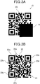
- FIG. 2A is a diagram illustrating an example of the information code 10 according to the first embodiment
- FIG. 2B is a diagram illustrating the information code 10 of FIG. 2A with a masked portion 11 removed therefrom.
- the information code 10 includes a code region 20 formed of a plurality of light-colored modules and dark-colored modules and a masked portion 11 configured to mask a part of the code region 20.
- the code region 20 is formed by arranging a plurality of square light-colored modules and square dark-colored modules in a matrix, like a QR code, and the overall code region 20 forms a square area.
- the code region 20 includes a data region 21 configured to include the required necessary information, three location detection patterns 22a to 22c, and format codes 23a to 23d, like a QR code.
- the location detection patterns 22a to 22c are patterns configured to specify the location of the corresponding code region 20 with respect to the captured image data, and are disposed in three of the four corners of the code region 20.
- the format codes 23a to 23d are disposed near the location detection patterns 22a to 22c, and are configured to specify format information that is used to read the corresponding information code 10, such as the area of the data region 21, the type of code being used, the module size, the mask pattern, and the error correction rate. For this reason, if most of the data region 21 is concealed or the location detection patterns 22a to 22c or format codes 23a to 23d are concealed, the code region 20 cannot be read.
- Each light-colored module of the modules constituting the code region 20 is configured to exhibit the reflective characteristics of light color when the module is irradiated with light of a first wavelength band in the visible light region or light of a second wavelength band different from the first wavelength.
- Each dark-colored module is configured to exhibit the reflective characteristics of dark color when the module is irradiated with light of a first wavelength band or light of a second wavelength band. More specifically, the modules that constitute the code region 20 are formed by applying ink that is commonly used.
- the masked portion 11 is a predetermined region of the code region 20 that intercepts light and thereby prevents a corresponding code region 20 from being read.
- the masked portion 11 is disposed to mask most of the data region 21.
- the masked portion 11 is formed by applying ink that transmits light reflected from the modules of the code region 20 when the light of a second wavelength band is radiated and prevents the light of a first wavelength band from being transmitted, for example, infrared ray-transmittable ink. For this reason, in a normal state where visible light is dominant, most of the data region 21 is seen as being concealed by the masked portion 11, as shown in FIG. 2A . Furthermore, the masked portion 11 is disposed to mask, for example, 30% of the data region 21 to the extent that the corresponding code region 20 cannot be read even when error correction processing is performed.
- the control unit 41 when information to be used to initiate the reading process is input to the control unit 41 by manipulating the manipulation unit 47 of the information code reader 40, the control unit 41 performs control and light of a second wavelength band is radiated by the second illumination light sources 44. Furthermore, when the information code 10 is captured by the imaging unit 42 while the light of a second wavelength band is being radiated onto the information code 10, the light of a second wavelength band passes through the masked portion 11, and therefore the code region 20 is captured without the masked portion 11 interfering image capture.
- the code region 20 captured with the masked portion 11 removed therefrom has a configuration identical to that of a typical QR code, the corresponding code region 20, that is, information code 10, is read by performing well-known decoding on the code region 20, thereby acquiring specific information.
- the code region 20 is captured with the predetermined region covered with the masked portion 11. As a result, the code region 20 cannot be read, thereby preventing the corresponding information code 10 from being read by an ordinary reader.
- the plurality of light-colored modules exhibiting the reflective characteristics of light color (i.e., light reflection characteristics or high reflectivity) when light of a second wavelength band is radiated and the plurality of dark-colored modules exhibiting the reflective characteristics of dark color (i.e., dark reflection characteristics or low reflectivity) when light of a second wavelength band is radiated are arranged in the code region 20.
- the information code 10 configured as described above allows the code region 20 to be captured without interference from the masked portion 11 when the light of a second wavelength band is radiated. Accordingly, specific information can be read from the code region 20 using the information code reader 40 capable of radiating the light of a second wavelength band. Meanwhile, it is impossible or difficult to read the corresponding information code 10 using an ordinary reader because the code region 20 cannot be completely captured because of the interruption by the masked portion 11. As a result, only a specific user who uses the information code reader 40 can read the specific information, and therefore the security of the corresponding information code 10 can be enhanced.
- the reading of the corresponding information code 10 by an ordinary reader is rendered difficult.
- the information code 10 is read using the information code reader 40 capable of radiating light of a second wavelength band, the information code 10 can be read reliably.
- the code region 20 cannot be copied in legible form (that is, in the form in which the light-colored modules and the dark-colored modules are separated from one another and reading is possible) because of the masked portion 11. Accordingly, the divulgence and dissemination of data based on the copying of the information code 10 can be effectively prevented.
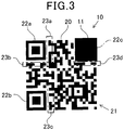
- FIG. 3 is a diagram illustrating an example of an information code 10 according to a first variant of the first embodiment.
- a masked portion 11 may be disposed to mask the location detection pattern 22c as a predetermined region of the code region 20 in which light is intercepted and which prevents the corresponding code region 20 from being read.
- the code region 20 cannot be read without using the information code reader 40, thereby preventing the corresponding information code 10 from being read using an ordinary reader.
- the above effects are achieved even when the masked portion 11 is disposed to mask at least one of the location detection patterns 22a to 22c or at least one of the format codes 23a to 23d.
- the location detection patterns 22a to 22c may correspond to examples of "location detection regions" described in the claims
- the format codes 23a to 23d may correspond to examples of "format information regions” described in the claims.
- the masked portion 11 is disposed to mask most of the data region or at least part of the location detection patterns of each code as the predetermined region that prevents the corresponding code region 20 from being read when the modules of the code region 20 are a data matrix code, a MaxiCode, or an Aztec code, the same effects can be achieved.
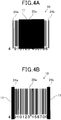
- FIGS. 4(A) and 4(B) are diagrams illustrating an example of an information code according to a second variant of the first embodiment.
- the code region 20a may be configured such that a plurality of characters formed by arranging a plurality of light-colored modules and dark-colored modules is arranged in the direction of reading, as in a barcode.
- the masked portion 11 is disposed to mask a predetermined region of the code region 20a in which light is intercepted and which prevents the corresponding code region 20a from being read.
- the code region 20a cannot be read without using the information code reader 40, thereby preventing the corresponding information code 10 from being read using an ordinary reader.
- the effect can be achieved even when masked portions 11 are disposed to mask the start character 24a of the characters, that is, a symbol indicative of the start of reading, and a stop character 24b, that is, a symbol indicative of the end of reading, as shown in FIG. 4B . Furthermore, the effect can be achieved even when a masked portion 11 is disposed to mask at least any one of the start and stop characters 24a and 24b.
- the effect can be achieved when the masked portion 11 is disposed to mask a predetermined region that prevents a code region 20a from being read or at least any one of a symbol indicative of the start of reading and a symbol indicative of the end of reading if the corresponding code region 20a is a one-dimensional code of a type different from that of a barcode.
- FIG. 5 is a diagram illustrating an example of an information code 10a according to a second embodiment.
- the information code 10a according to the second embodiment is different from the information code according to the first embodiment in that the information code 10a employs a masked portion 12 in the shape of a specific figure, instead of the above-described masked portion 11.
- the masked portion 12 is the shape of a specific figure designed in response to the environment of use, for example, a star figure. Even when the masked portion 12 is formed in the shape of a specific figure as described above, the masked portion 12 allows light, reflected from the code region 20 when light of a second wavelength band is radiated, to pass therethrough, thereby realizing an information code 10a having enhanced security and improved design. Furthermore, although the color of the masked portion 12 in the shape of a star figure is generally and chiefly blackish because of the balanced use of ink or the like, a white star figure is illustrated in FIG. 5 for convenience of description.
- the shape of the masked portion 12 is not limited to the star figure. Furthermore, the effect can still be achieved even when the masked portion 12 is designed to have a specific figure whose shape, pattern and color is varied depending on the environment of use.
- FIG. 6A is a diagram illustrating an example of the information code according to the third embodiment
- FIG. 6B is a diagram illustrating the information code of FIG. 6A with a masked portion removed therefrom.
- the information code 10b according to the third embodiment is different from the information code according to the first embodiment in that the information code 10b employs a masked portion 13 masking the entire code region 20, instead of the above-described masked portion 11.
- the masked portion 13 is disposed to mask the entire code region 20, and therefore a user cannot view the original code region 20, so that the information code 10b cannot be recognized using an ordinary reader that is used by the user, thereby reliably preventing the corresponding information code 10b from being read.
- the information code reader 40 is used, capturing is performed while light of a second wavelength band is being radiated. Since the code region 20 is captured, as shown in FIG. 6B , the corresponding information code 10b can be read.
- FIG. 7A is a diagram illustrating an example of the information code according to the fourth embodiment
- FIG. 7B is a diagram illustrating the information code of FIG. 7A with a masked portion removed therefrom.
- the information code 10c according to the fourth embodiment is different from the information code according to the third embodiment in that the information code 10c employs a masked portion 14, instead of the above-described masked portion 13.
- the masked portion 14 includes a QR code that enables predetermined information to be read, and is disposed to mask the entire code region 20. That is, the masked portion 14 includes another information code in which a plurality of light-colored modules exhibiting the reflective characteristics of light color when light of a first wavelength band is radiated and a plurality of dark-colored modules exhibiting the reflective characteristics of dark color when light of a first wavelength band is radiated are arranged.
- the corresponding masked portion 14 is read as a common information code by an ordinary reader, and therefore the code region 20 coated with the masked portion 14 cannot be read without using the information code reader 40.
- the code region 20 coated with the masked portion 14 can be captured, as shown in FIG. 7B .
- another information code formed of the masked portion 14 can be captured, as shown in FIG. 7A .
- the information code reader 40 capable of radiating light of two wavelength bands is used. Since two types of information can be read from the space of a single information code, the efficiency of code space can be achieved.
- the masked portion 14 may use a mask pattern that varies the feature of each module, and include a QR code in which the features of the modules constitute the code region 20.
- a mask pattern in which a plurality of light-colored modules and dark-colored modules have been arranged in a matrix is prepared.
- the masked portion 14 is configured such that when the mask pattern is superimposed on the code region 20, a dark-colored module is disposed at a location where modules of the same color are superimposed on each other and a light-colored module is disposed at a location where modules of different colors are superimposed on each other.
- the masked portion 14 is configured so that the features of the modules of the code region 20 vary depending on the mask pattern. Accordingly, an ordinary reader needs to remove the mask pattern after capturing the masked portion 14, while the information code reader 40 can capture and read the code region 20 without performing the removal process.
- a masked portion 14 may be formed of a QR code that is formed by applying infrared ray-transmittable ink of different concentrations and enables predetermined information to be read.
- FIGs. 8A and 8B are diagrams illustrating an example of an information code according to a first variant of the fourth embodiment, wherein FIG. 8A illustrates the application of a base 14a, and FIG. 8B is the printing of a QR code on the base 14a.
- the base 14a is formed by lightly coating a target code region 20 with infrared ray-transmittable ink so that the code region 20 cannot be recognized. Furthermore, as shown in FIG. 8B , a dark-colored module region 14b is formed by applying infrared ray-transmittable ink. By doing this, a masked portion 14 that masks the code region 20 is formed.
- the code region 20 is prevented from being read by an ordinary reader, and two types of information can be read from the space of a single information code using the information code reader 40 capable of radiating light of two wavelength bands, thereby achieving the efficiency of code space.
- the masked portion 14 or dark-colored module region 14b is not limited to a portion or region of a type identical to that of the target code region 20 (in the present embodiment, a QR code), but may be a different type of information code.
- the masked portion 14 or base 14a is not limited to a portion or base disposed to mask the entire code region 20, but is disposed to mask a predetermined region that prevents the code region 20 from being read, like the masked portion 11.
- FIG. 9A is a diagram illustrating an example of an information code 10d according to the fifth embodiment
- FIG. 9B is a diagram illustrating the information code 10d of FIG. 9A with a masked portion 11 removed therefrom.
- the information code 10d according to the fifth embodiment is different from the information code according to the first embodiment in that the information code 10d employs a second masked portion 30 in addition to the above-described masked portion 11.
- the second masked portion 30 is formed of material having transparency at a temperature higher than room temperature, and has a size almost identical to that of the masked portion 11 and is disposed at a location almost identical to that of the masked portion 11, with respect to the code region 20, as shown in FIGS. 9(A) and 9(B) .
- the information code 10d configured as described above is captured while light of a second wavelength band is being radiated, the information code 10d is captured with the code region 20 coated with the second masked portion 30, as shown in FIG. 9B . That is, the code region 20 cannot be captured to be read with respect for the second masked portion 30 only by the radiation of the light of a second wavelength band, and the second masked portion 30 needs to be higher than room temperature to enable the second masked portion 30 to transmit light.
- the second masked portion 30 is not limited to a portion that has a size almost identical to that of the masked portion 11 and is disposed on the identical location with respect to the code region 20, but may have a different size or may be disposed at a different location as long as it coats at least the predetermined region.
- FIGs. 10A and 10B are diagrams illustrating an example of an information code 10e according to a sixth embodiment, wherein FIG. 10A shows a code region 20 with a masked portion 15 removed therefrom, and FIG. 10B shows the code region 20 whose part is coated with a masked portion 15.
- the information code 10e according to the sixth embodiment is different from the information code according to the first embodiment in that a masked portion 15 separate from a code region 20 is employed, instead of the above-described masked portion 11.
- the masked portion 15 is formed of a seal member that is formed of an infrared ray-transmittable material that allows light of a second wavelength band to pass therethrough and thereby interrupts light of a first wavelength band.
- the masked portion 15 is formed separately so that it can be added to a predetermined region when desired.
- an existing information code can be prevented from being read using an ordinary reader by coating the predetermined region of an existing information code with the masked portion 15 configured as described above.
- the information code reader 40 capable of radiating light of a second wavelength band, the information code can be reliably read.
- the masked portion 15 is formed of the seal member, the predetermined region of an existing information code can be easily coated with the corresponding masked portion 15.
- FIG. 11 is a diagram illustrating an example of an information code 10e according to a variant of the sixth embodiment.
- the masked portion 16 may be configured by adding infrared ray-transmittable ink in such a way as to apply (print) the infrared ray-transmittable ink onto the predetermined region. Even in this case, the predetermined region of an existing information code can be easily coated with the corresponding masked portion 16.
- the reading of an ordinary QR code by an ordinary reader is rendered impossible or difficult by, for example, applying (printing) a desired letter, such as a Japanese kanji (as shown in Fig. 11 ), onto the ordinary QR code using infrared ray-transmittable ink as the masked portion 16, as shown in FIG. 11 .
- a desired letter such as a Japanese kanji (as shown in Fig. 11 )
- infrared ray-transmittable ink as the masked portion 16
- FIG. 11 shows that when management is inconvenient because a code has to be read again (in the case of the inspection of products, the inspection of inventory in a warehouse, etc.), reading is prevented from being performed twice using an ordinary reader, so that the completion of the reading of the corresponding QR code can be easily seen and the redundant reading of the information code can be prevented.
- the same effect can be achieved using the above-described masked portion 16.
- the corresponding QR code can be read by performing reading using the information code reader 40 capable of radiating light of a second wavelength band.
- the masked portion configured separately, like the code region 20 is not limited to a portion formed by adding a seal member or applying ink, like the masked portions 15 and 16, but may be configured such that a member made of a material that allows light of a second wavelength band to pass therethrough and thereby interrupts light of a first wavelength band is added to the predetermined region later using, for example, a printing or stamping method.
- FIG. 12 is a diagram illustrating an example of an information code 10g according to the seventh embodiment.
- the information code 10g according to the seventh embodiment is different from the information code according to the first embodiment in that the above-described masked portion 18 is disposed to mask the region other than the location detection patterns 22a to 22c.
- the region other than the location detection patterns 22a to 22c, which is coated with the masked portion 18, cannot be recognized without reading the information code 10g using the information code reader 40, thereby preventing the corresponding information code 10g from being read using an ordinary reader.
- the location detection patterns 22a to 22c are not coated with the masked portion 18, a user can be visually notified of the presence of the corresponding location detection patterns 22a to 22c. For this reason, the user can recognize the locations of the location detection patterns 22a to 22c, so that the corresponding information code 10g can be reliably read by accurately directing the reading unit of the information code reader 40 toward the corresponding information code 10g when the information code reader 40 is used.
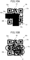
- FIG. 13A is a diagram schematically illustrating an information code according to a first variant of the foregoing embodiments
- FIG. 13B is a diagram schematically illustrating an information code according to a second variant of the foregoing embodiments.
- a masked portion 19b may be disposed to mask an L-shaped region extending from the left edge 25a of a code region 20 to the bottom edge 25c thereof.
- a masked portion 19c may be configured to connect a plurality of figures (in the example of FIG. 13B , circles) and disposed to mask a region extending from some edges of a code region 20 to another edge thereof.
- FIG. 14 is a flowchart illustrating a reading process that is performed by the information code reader according to the eighth embodiment.
- the information code reader 40 according to the eighth embodiment is intended to be used for information codes each of which has a masked portion disposed to mask the code region 20 except for characteristic pattern regions (the location detection patterns 22a to 22c), like the above-described information codes 10g and 10h.
- the information code reader 40 according to the ninth embodiment is different from the information code reader according to the first embodiment in that the information code reader 40 reads an information code using already extracted characteristic pattern regions.
- first illumination light is radiated by the first illumination light sources 43 (first illumination light radiation means) at step S101. Thereafter, while the first illumination light is being radiated onto the information code and second illumination light is not being radiated onto the information code, the corresponding information code is captured using the imaging unit 42 at step S103. Thereafter, characteristic pattern regions are extracted from a captured image of the information code using a known extraction method at step S105.
- a method of extracting characteristic pattern regions has been generally determined according to the type of information code in specifications or the like.
- location detection patterns are extracted as characteristic pattern regions using a known method for extracting the location detection patterns of QR code.
- the decoding fails because the data region 21 is coated with the masked portion 18 even when the respective location detection patterns 22a to 22c are extracted at step S105.
- second illumination light is radiated by the second illumination light sources 44 at step S113.
- the information code 10g is captured by the imaging unit 42 at step S115.
- decoding is performed at step S119 using the results of the extraction (which was performed at step S115) of the characteristic patterns.
- the locations of the respective location detection patterns 22a to 22c are found, and therefore the locations of the respective location detection patterns 22a to 22c do not need to be newly detected, so that this processing is shortened or eliminated, thereby achieving rapid decoding.
- second illumination step S113 when the location detection patterns 22a to 22c are extracted, second illumination light may be radiated onto only what is estimated to be a code region based on the location detection patterns 22a to 22c. By doing so, power consumption can be reduced.
- step S107 Since the extraction of the characteristic patterns has been successful (No at step S107), second illumination light is radiated and the information code is captured while the second illumination light is being radiated. In this case (No at step S117), decoding is performed at step S121. At a decoding step at S121, processing including the extraction of the characteristic pattern regions is performed. After step S119 or S121, it is determined whether the decoding has been successful at step S123. If the decoding has been successful (Yes at step S123), the transmission of data to the outside is performed at step S125, thereby terminating the reading process. Meanwhile, if it is determined that the decoding has not been successful at step S123 (No at step S123), the process following step S101 is repeated.
- the second illumination light sources 44 may correspond to an example of illumination means
- the imaging unit 42 may correspond to capturing means
- the control unit 41 may be an example of reading means.
- the location detection patterns 22a to 22c are extracted as characteristic pattern regions and the code region 20 is not extracted from an image that is captured while light of a first wavelength band is being radiated, light of a second wavelength band is radiated.
- the location of the code region 20 is specified based on the location detection patterns 22a to 22c extracted while light of a first wavelength band is being radiated, and the corresponding code region 20 is read based on the arrangement of the modules that constitute the extracted code region 20 whose location is specified.
- the corresponding code region 20 is not extracted and cannot be read even when the location detection patterns 22a to 22c of the code region 20 are extracted.
- the location of the code region 20 can be specified based on the extracted location detection patterns 22a to 22c, as described above. By doing so, the extraction of the location detection patterns 22a to 22c is not necessary, so that the time it takes to read the corresponding information code can be shortened and the load of the reading process can be reduced.
- the information code reader 40 is not limited to the reader configured to radiate the first illumination light using the first illumination light sources 43, but may be a reader without the first illumination light sources 43, which uses surrounding illumination.
- the present invention is not limited to the embodiments and their variants, but may be embodied, as follows:
Landscapes
- Physics & Mathematics (AREA)
- Engineering & Computer Science (AREA)
- General Physics & Mathematics (AREA)
- Theoretical Computer Science (AREA)
- Electromagnetism (AREA)
- Computer Vision & Pattern Recognition (AREA)
- General Health & Medical Sciences (AREA)
- Toxicology (AREA)
- Artificial Intelligence (AREA)
- Health & Medical Sciences (AREA)
- Multimedia (AREA)
- Credit Cards Or The Like (AREA)
- Cash Registers Or Receiving Machines (AREA)
- Spectrometry And Color Measurement (AREA)
Claims (14)
- Code d'informations bidimensionnel, dans lequel une région de code (20, 20a) est prévue,
une région de données (21) et une pluralité de motifs caractéristiques (22a - 22c) sont prévus dans la région de code, et une pluralité de modules de couleur claire et une pluralité de modules de couleur sombre sont agencés dans la région de données de la région de code, chacun de la pluralité de motifs caractéristiques (22a - 22c) est composé d'une pluralité de modules composée d'une combinaison des modules de couleur claire et des modules de couleur sombre,
caractérisé en ce que
la pluralité de modules de couleur claire présente des caractéristiques réfléchissantes de la couleur claire uniquement lorsque de la lumière d'une seconde bande de longueur d'ondes différente de la lumière d'une première bande de longueur d'ondes est irradiée,
la pluralité de modules de couleur sombre présentant des caractéristiques réfléchissantes de la couleur sombre uniquement lorsque la lumière de la seconde bande de longueur d'ondes est irradiée, et
le code d'informations comprenant :une portion masquée (11) disposée dans la région de code de manière à masquer une région prédéterminée de la région de code, la région prédéterminée incluant une partie des motifs caractéristiques, la portion masquée étant composée d'un matériau qui interrompt le passage de la lumière de la première bande de longueur d'ondes à travers la portion masquée et qui permet le passage de la lumière de la seconde bande de longueur d'ondes à travers la portion masquée. - Code d'informations selon la revendication 1, dans lequel :la portion masquée est disposée pour masquer la totalité des motifs caractéristiques.
- Code d'informations selon la revendication 1, dans lequel :la région de code inclut des régions d'informations de format (23a - 23d) configurées pour acquérir des informations de format pour lire le code d'informations correspondant sont incluses dans la région de code ; etla portion masquée est disposée pour masquer les motifs caractéristiques et les régions d'informations de format.
- Code d'informations selon la revendication 1, dans lequel :la région de code inclut les régions de motif caractéristiques formées dans des formes définies à des emplacements prédéterminés.
- Code d'informations selon la revendication 1, dans lequel :les motifs caractéristiques sont des régions de détection d'emplacement formées dans des formes définies à des emplacements prédéterminés dans la région de code ; etla portion masquée est disposée pour masquer les régions de détection d'emplacement et une zone autre que les régions de détection d'emplacement dans la région de code.
- Code d'informations selon l'une quelconque des revendications 1 à 5, dans lequel la portion masquée est formée dans une forme de dessin dont la forme, le motif ou la couleur sont variables.
- Code d'informations selon la revendication 1, dans lequel la portion masquée est disposée pour masquer la région de code entière.
- Code d'informations selon l'une quelconque des revendications 1 à 5, dans lequel la portion masquée est configurée comme un autre code d'informations dans lequel une pluralité de modules de couleur claire présentant des caractéristiques réfléchissantes de la couleur claire lorsque la lumière de la seconde bande de longueur d'ondes est irradiée, et une pluralité de modules de couleur sombre présentant des caractéristiques réfléchissantes de la couleur sombre lorsque de la lumière de la seconde bande de longueur d'ondes est irradiée, sont agencées, et qui a des informations différentes des informations acquises de la région de code.
- Code d'informations selon l'une quelconque des revendications 1 à 5, dans lequel une seconde portion masquée (30) ayant une transparence à la lumière à une température supérieure à la température ambiante est disposée dans la région prédéterminée de manière à recouvrir la portion masquée (11).
- Code d'informations selon l'une quelconque des revendications 1 à 5, dans lequel la portion masquée est configurée comme une portion séparée (15) qui peut être appliquée à la région prédéterminée lorsque cela est souhaité.
- Code d'informations selon la revendication 10, dans lequel la portion masquée est prévue sous la forme d'un élément de scellage pouvant être fixé à la région de code.
- Code d'informations selon la revendication 10, dans lequel le matériau de la portion masquée est de l'encre qui est adaptée pour être appliquée sur la région de code.
- Lecteur de code d'informations (40) destiné à lire de manière optique le code d'informations bidimensionnel selon l'une quelconque des revendications 1 à 12,
le lecteur de code d'informations comprenant :un moyen d'éclairage (44) capable d'irradier au moins la lumière de la seconde bande de longueur d'ondes sur le code d'informations muni de la région de code incluant la région masquée ;un moyen de capture (42) pour capturer le code d'informations sur lequel au moins la lumière de la seconde bande de longueur d'ondes est irradiée ; etun moyen de lecture pour lire (41) la région de code correspondante sur la base d'un agencement des modules qui sont extraits d'une image du code d'informations capturée par le moyen de capture et qui constituent la région de code incluant la région masquée. - Lecteur de code d'informations selon la revendication 13, dans lequel le lecteur de code d'informations comprend :le moyen de lecture (41) spécifie l'emplacement de la région de code sur la base des régions de détection d'emplacement extraites d'une image du code d'informations capturée par le moyen de capture, et lit la région de code correspondante sur la base d'un agencement des modules de la région de code extraite dont l'emplacement est spécifié ;dans lequel le moyen d'éclairage irradie la lumière de la seconde bande de longueur d'ondes si les régions de détection d'emplacement sont extraites et la région de code n'est pas extraite de l'image qui est capturée par le moyen de capture en réponse à l'irradiation de la lumière de la première bande de longueur d'ondes ; etdans lequel le moyen de lecture, par rapport à l'image qui est capturée par le moyen de capture tandis que la lumière d'une première bande de longueur d'ondes est irradiée, spécifie l'emplacement de la région de code sur la base des régions de détection d'emplacement extraites en réponse à l'irradiation de la lumière de la première bande de longueur d'ondes, et lit la région de code correspondante sur la base agencement des modules de la région de code extraite dont l'emplacement est spécifié.
Applications Claiming Priority (2)
| Application Number | Priority Date | Filing Date | Title |
|---|---|---|---|
| JP2011144667 | 2011-06-29 | ||
| JP2011264539 | 2011-12-02 |
Publications (3)
| Publication Number | Publication Date |
|---|---|
| EP2541470A2 EP2541470A2 (fr) | 2013-01-02 |
| EP2541470A3 EP2541470A3 (fr) | 2013-05-15 |
| EP2541470B1 true EP2541470B1 (fr) | 2017-10-04 |
Family
ID=45992043
Family Applications (1)
| Application Number | Title | Priority Date | Filing Date |
|---|---|---|---|
| EP12159451.9A Active EP2541470B1 (fr) | 2011-06-29 | 2012-03-14 | Code d'informations et lecture de code d'informations |
Country Status (5)
| Country | Link |
|---|---|
| US (1) | US9129198B2 (fr) |
| EP (1) | EP2541470B1 (fr) |
| KR (1) | KR101350375B1 (fr) |
| CN (1) | CN102855511B (fr) |
| SG (1) | SG186534A1 (fr) |
Families Citing this family (10)
| Publication number | Priority date | Publication date | Assignee | Title |
|---|---|---|---|---|
| US10565483B2 (en) * | 2012-08-31 | 2020-02-18 | International Business Machines Corporation | Two-dimensional barcode to avoid unintentional scanning |
| GB201314642D0 (en) * | 2013-08-15 | 2013-10-02 | Summerfield Gideon | Image Identification System and Method |
| US9552542B2 (en) | 2014-11-20 | 2017-01-24 | International Business Machines Corporation | Encoding information in multiple patterned layers |
| EP3031750A1 (fr) * | 2014-12-11 | 2016-06-15 | Qbo Coffee GmbH | Capsule de boisson, système de préparation de boissons et procédé d'identification d'une capsule de boisson |
| EP3031749A1 (fr) * | 2014-12-11 | 2016-06-15 | Qbo Coffee GmbH | Capsule de boisson, système de préparation de boissons et procédé d'identification d'une capsule de boisson |
| JP2017091140A (ja) * | 2015-11-09 | 2017-05-25 | 三星電子株式会社Samsung Electronics Co.,Ltd. | コード送受信システム、コード受信装置、コード送信装置、コード受信方法、コード送信方法、及びプログラム |
| CN105809227A (zh) * | 2016-03-22 | 2016-07-27 | 上海透云物联网科技有限公司 | 一种识别码结构及加密、防伪、监控、有奖销售方法 |
| JP7118748B2 (ja) | 2018-06-01 | 2022-08-16 | 富士通コンポーネント株式会社 | 計測器および光学読取器 |
| CN108985420B (zh) * | 2018-08-01 | 2021-06-01 | 深圳大学 | 一种信息码的编解码方法及解码系统 |
| US12118427B2 (en) * | 2021-01-26 | 2024-10-15 | Nec Corporation Of America | Invisible coated infrared patterns |
Citations (1)
| Publication number | Priority date | Publication date | Assignee | Title |
|---|---|---|---|---|
| US20090323959A1 (en) * | 2007-05-29 | 2009-12-31 | Denso Wave Incorporated | Method for producing two-dimensional code reader for reading the two-dimensional code |
Family Cites Families (8)
| Publication number | Priority date | Publication date | Assignee | Title |
|---|---|---|---|---|
| DE3636921A1 (de) | 1986-10-30 | 1988-05-05 | Interflex Datensyst | Faelschungssicherer optoelektrischer code-kartenleser |
| FR2682790B1 (fr) * | 1991-10-18 | 1998-02-27 | Sogedex | Procede et dispositif de lecture d'un code a barres avec reconnaissance de la presence d'un masque infrarouge. |
| US6119943A (en) | 1994-12-12 | 2000-09-19 | Moore Business Forms, Inc. | Multi-layer bar code arrangement using wavelength separation |
| US5703348A (en) | 1994-12-26 | 1997-12-30 | Kabushiki Kaisha Tec | Hand-held optical code reader |
| JP4162884B2 (ja) * | 2001-11-20 | 2008-10-08 | 信越化学工業株式会社 | 耐食性希土類磁石 |
| US6913199B2 (en) | 2002-12-18 | 2005-07-05 | Symbol Technologies, Inc. | System and method for verifying optical character recognition of optical code reads |
| JP4665710B2 (ja) | 2005-10-21 | 2011-04-06 | 株式会社デンソーウェーブ | 情報コード担体 |
| US20100243747A1 (en) * | 2007-10-25 | 2010-09-30 | Takahiro Saito | Information code |
-
2012
- 2012-03-14 EP EP12159451.9A patent/EP2541470B1/fr active Active
- 2012-03-15 KR KR1020120026750A patent/KR101350375B1/ko active IP Right Grant
- 2012-03-15 CN CN201210068499.0A patent/CN102855511B/zh active Active
- 2012-03-15 SG SG2012018875A patent/SG186534A1/en unknown
- 2012-03-15 US US13/421,414 patent/US9129198B2/en active Active
Patent Citations (1)
| Publication number | Priority date | Publication date | Assignee | Title |
|---|---|---|---|---|
| US20090323959A1 (en) * | 2007-05-29 | 2009-12-31 | Denso Wave Incorporated | Method for producing two-dimensional code reader for reading the two-dimensional code |
Also Published As
| Publication number | Publication date |
|---|---|
| EP2541470A3 (fr) | 2013-05-15 |
| US9129198B2 (en) | 2015-09-08 |
| SG186534A1 (en) | 2013-01-30 |
| EP2541470A2 (fr) | 2013-01-02 |
| KR20130004052A (ko) | 2013-01-09 |
| US20130001310A1 (en) | 2013-01-03 |
| CN102855511A (zh) | 2013-01-02 |
| CN102855511B (zh) | 2016-05-25 |
| KR101350375B1 (ko) | 2014-01-13 |
Similar Documents
| Publication | Publication Date | Title |
|---|---|---|
| EP2541470B1 (fr) | Code d'informations et lecture de code d'informations | |
| JP6347295B2 (ja) | 情報コードおよび情報コード読取装置 | |
| US9477867B2 (en) | System and method to manipulate an image | |
| CN108073845B (zh) | 光学标记的读取器 | |
| EP3496001B1 (fr) | Lecteur d'indices comportant un capteur d'image multifonction filtré | |
| US8763917B2 (en) | Machine-readable symbols | |
| US20120211555A1 (en) | Machine-readable symbols | |
| US20040126036A1 (en) | Method and apparatus for selective processing of captured images | |
| US9165230B2 (en) | Information code and information code reading apparatus | |
| EP2458527A2 (fr) | Système de lecture de code d'informations et support sur lequel le code d'information est formé | |
| EP3000073A1 (fr) | Identification de codes-barres mono- ou bidimensionnels via une combinaison pondérée de données d'images | |
| EP2105832B1 (fr) | Schéma de procédé pour lecteur d'indices | |
| JP2015210612A (ja) | 情報コード読取装置 | |
| EP3174016B1 (fr) | Balayage activé filigrané | |
| US12052404B2 (en) | Digital watermark enabled scanner with white illumination source | |
| EP4024268A1 (fr) | Système et procédé de lecture de code d'informations et support sur lequel est formé le code d'informations |
Legal Events
| Date | Code | Title | Description |
|---|---|---|---|
| PUAI | Public reference made under article 153(3) epc to a published international application that has entered the european phase |
Free format text: ORIGINAL CODE: 0009012 |
|
| AK | Designated contracting states |
Kind code of ref document: A2 Designated state(s): AL AT BE BG CH CY CZ DE DK EE ES FI FR GB GR HR HU IE IS IT LI LT LU LV MC MK MT NL NO PL PT RO RS SE SI SK SM TR |
|
| AX | Request for extension of the european patent |
Extension state: BA ME |
|
| PUAL | Search report despatched |
Free format text: ORIGINAL CODE: 0009013 |
|
| AK | Designated contracting states |
Kind code of ref document: A3 Designated state(s): AL AT BE BG CH CY CZ DE DK EE ES FI FR GB GR HR HU IE IS IT LI LT LU LV MC MK MT NL NO PL PT RO RS SE SI SK SM TR |
|
| AX | Request for extension of the european patent |
Extension state: BA ME |
|
| RIC1 | Information provided on ipc code assigned before grant |
Ipc: G06K 19/06 20060101AFI20130409BHEP Ipc: G06K 7/10 20060101ALI20130409BHEP |
|
| 17P | Request for examination filed |
Effective date: 20131115 |
|
| RBV | Designated contracting states (corrected) |
Designated state(s): AL AT BE BG CH CY CZ DE DK EE ES FI FR GB GR HR HU IE IS IT LI LT LU LV MC MK MT NL NO PL PT RO RS SE SI SK SM TR |
|
| 17Q | First examination report despatched |
Effective date: 20150520 |
|
| GRAP | Despatch of communication of intention to grant a patent |
Free format text: ORIGINAL CODE: EPIDOSNIGR1 |
|
| INTG | Intention to grant announced |
Effective date: 20170410 |
|
| GRAS | Grant fee paid |
Free format text: ORIGINAL CODE: EPIDOSNIGR3 |
|
| GRAA | (expected) grant |
Free format text: ORIGINAL CODE: 0009210 |
|
| AK | Designated contracting states |
Kind code of ref document: B1 Designated state(s): AL AT BE BG CH CY CZ DE DK EE ES FI FR GB GR HR HU IE IS IT LI LT LU LV MC MK MT NL NO PL PT RO RS SE SI SK SM TR |
|
| RAP1 | Party data changed (applicant data changed or rights of an application transferred) |
Owner name: DENSO WAVE INCORPORATED |
|
| REG | Reference to a national code |
Ref country code: GB Ref legal event code: FG4D |
|
| REG | Reference to a national code |
Ref country code: CH Ref legal event code: EP |
|
| REG | Reference to a national code |
Ref country code: AT Ref legal event code: REF Ref document number: 934677 Country of ref document: AT Kind code of ref document: T Effective date: 20171015 |
|
| REG | Reference to a national code |
Ref country code: IE Ref legal event code: FG4D |
|
| REG | Reference to a national code |
Ref country code: DE Ref legal event code: R096 Ref document number: 602012038035 Country of ref document: DE |
|
| REG | Reference to a national code |
Ref country code: NL Ref legal event code: MP Effective date: 20171004 |
|
| REG | Reference to a national code |
Ref country code: LT Ref legal event code: MG4D |
|
| REG | Reference to a national code |
Ref country code: AT Ref legal event code: MK05 Ref document number: 934677 Country of ref document: AT Kind code of ref document: T Effective date: 20171004 |
|
| REG | Reference to a national code |
Ref country code: FR Ref legal event code: PLFP Year of fee payment: 7 |
|
| PG25 | Lapsed in a contracting state [announced via postgrant information from national office to epo] |
Ref country code: NL Free format text: LAPSE BECAUSE OF FAILURE TO SUBMIT A TRANSLATION OF THE DESCRIPTION OR TO PAY THE FEE WITHIN THE PRESCRIBED TIME-LIMIT Effective date: 20171004 |
|
| PG25 | Lapsed in a contracting state [announced via postgrant information from national office to epo] |
Ref country code: NO Free format text: LAPSE BECAUSE OF FAILURE TO SUBMIT A TRANSLATION OF THE DESCRIPTION OR TO PAY THE FEE WITHIN THE PRESCRIBED TIME-LIMIT Effective date: 20180104 Ref country code: ES Free format text: LAPSE BECAUSE OF FAILURE TO SUBMIT A TRANSLATION OF THE DESCRIPTION OR TO PAY THE FEE WITHIN THE PRESCRIBED TIME-LIMIT Effective date: 20171004 Ref country code: FI Free format text: LAPSE BECAUSE OF FAILURE TO SUBMIT A TRANSLATION OF THE DESCRIPTION OR TO PAY THE FEE WITHIN THE PRESCRIBED TIME-LIMIT Effective date: 20171004 Ref country code: SE Free format text: LAPSE BECAUSE OF FAILURE TO SUBMIT A TRANSLATION OF THE DESCRIPTION OR TO PAY THE FEE WITHIN THE PRESCRIBED TIME-LIMIT Effective date: 20171004 Ref country code: LT Free format text: LAPSE BECAUSE OF FAILURE TO SUBMIT A TRANSLATION OF THE DESCRIPTION OR TO PAY THE FEE WITHIN THE PRESCRIBED TIME-LIMIT Effective date: 20171004 |
|
| PG25 | Lapsed in a contracting state [announced via postgrant information from national office to epo] |
Ref country code: HR Free format text: LAPSE BECAUSE OF FAILURE TO SUBMIT A TRANSLATION OF THE DESCRIPTION OR TO PAY THE FEE WITHIN THE PRESCRIBED TIME-LIMIT Effective date: 20171004 Ref country code: IS Free format text: LAPSE BECAUSE OF FAILURE TO SUBMIT A TRANSLATION OF THE DESCRIPTION OR TO PAY THE FEE WITHIN THE PRESCRIBED TIME-LIMIT Effective date: 20180204 Ref country code: AT Free format text: LAPSE BECAUSE OF FAILURE TO SUBMIT A TRANSLATION OF THE DESCRIPTION OR TO PAY THE FEE WITHIN THE PRESCRIBED TIME-LIMIT Effective date: 20171004 Ref country code: RS Free format text: LAPSE BECAUSE OF FAILURE TO SUBMIT A TRANSLATION OF THE DESCRIPTION OR TO PAY THE FEE WITHIN THE PRESCRIBED TIME-LIMIT Effective date: 20171004 Ref country code: LV Free format text: LAPSE BECAUSE OF FAILURE TO SUBMIT A TRANSLATION OF THE DESCRIPTION OR TO PAY THE FEE WITHIN THE PRESCRIBED TIME-LIMIT Effective date: 20171004 Ref country code: BG Free format text: LAPSE BECAUSE OF FAILURE TO SUBMIT A TRANSLATION OF THE DESCRIPTION OR TO PAY THE FEE WITHIN THE PRESCRIBED TIME-LIMIT Effective date: 20180104 Ref country code: GR Free format text: LAPSE BECAUSE OF FAILURE TO SUBMIT A TRANSLATION OF THE DESCRIPTION OR TO PAY THE FEE WITHIN THE PRESCRIBED TIME-LIMIT Effective date: 20180105 |
|
| REG | Reference to a national code |
Ref country code: DE Ref legal event code: R097 Ref document number: 602012038035 Country of ref document: DE |
|
| PG25 | Lapsed in a contracting state [announced via postgrant information from national office to epo] |
Ref country code: EE Free format text: LAPSE BECAUSE OF FAILURE TO SUBMIT A TRANSLATION OF THE DESCRIPTION OR TO PAY THE FEE WITHIN THE PRESCRIBED TIME-LIMIT Effective date: 20171004 Ref country code: CZ Free format text: LAPSE BECAUSE OF FAILURE TO SUBMIT A TRANSLATION OF THE DESCRIPTION OR TO PAY THE FEE WITHIN THE PRESCRIBED TIME-LIMIT Effective date: 20171004 Ref country code: SK Free format text: LAPSE BECAUSE OF FAILURE TO SUBMIT A TRANSLATION OF THE DESCRIPTION OR TO PAY THE FEE WITHIN THE PRESCRIBED TIME-LIMIT Effective date: 20171004 Ref country code: DK Free format text: LAPSE BECAUSE OF FAILURE TO SUBMIT A TRANSLATION OF THE DESCRIPTION OR TO PAY THE FEE WITHIN THE PRESCRIBED TIME-LIMIT Effective date: 20171004 |
|
| PLBE | No opposition filed within time limit |
Free format text: ORIGINAL CODE: 0009261 |
|
| STAA | Information on the status of an ep patent application or granted ep patent |
Free format text: STATUS: NO OPPOSITION FILED WITHIN TIME LIMIT |
|
| PG25 | Lapsed in a contracting state [announced via postgrant information from national office to epo] |
Ref country code: PL Free format text: LAPSE BECAUSE OF FAILURE TO SUBMIT A TRANSLATION OF THE DESCRIPTION OR TO PAY THE FEE WITHIN THE PRESCRIBED TIME-LIMIT Effective date: 20171004 Ref country code: RO Free format text: LAPSE BECAUSE OF FAILURE TO SUBMIT A TRANSLATION OF THE DESCRIPTION OR TO PAY THE FEE WITHIN THE PRESCRIBED TIME-LIMIT Effective date: 20171004 Ref country code: SM Free format text: LAPSE BECAUSE OF FAILURE TO SUBMIT A TRANSLATION OF THE DESCRIPTION OR TO PAY THE FEE WITHIN THE PRESCRIBED TIME-LIMIT Effective date: 20171004 |
|
| 26N | No opposition filed |
Effective date: 20180705 |
|
| REG | Reference to a national code |
Ref country code: CH Ref legal event code: PL |
|
| PG25 | Lapsed in a contracting state [announced via postgrant information from national office to epo] |
Ref country code: SI Free format text: LAPSE BECAUSE OF FAILURE TO SUBMIT A TRANSLATION OF THE DESCRIPTION OR TO PAY THE FEE WITHIN THE PRESCRIBED TIME-LIMIT Effective date: 20171004 Ref country code: MC Free format text: LAPSE BECAUSE OF FAILURE TO SUBMIT A TRANSLATION OF THE DESCRIPTION OR TO PAY THE FEE WITHIN THE PRESCRIBED TIME-LIMIT Effective date: 20171004 |
|
| REG | Reference to a national code |
Ref country code: BE Ref legal event code: MM Effective date: 20180331 |
|
| REG | Reference to a national code |
Ref country code: IE Ref legal event code: MM4A |
|
| PG25 | Lapsed in a contracting state [announced via postgrant information from national office to epo] |
Ref country code: LU Free format text: LAPSE BECAUSE OF NON-PAYMENT OF DUE FEES Effective date: 20180314 |
|
| PG25 | Lapsed in a contracting state [announced via postgrant information from national office to epo] |
Ref country code: IE Free format text: LAPSE BECAUSE OF NON-PAYMENT OF DUE FEES Effective date: 20180314 |
|
| PG25 | Lapsed in a contracting state [announced via postgrant information from national office to epo] |
Ref country code: BE Free format text: LAPSE BECAUSE OF NON-PAYMENT OF DUE FEES Effective date: 20180331 Ref country code: LI Free format text: LAPSE BECAUSE OF NON-PAYMENT OF DUE FEES Effective date: 20180331 Ref country code: CH Free format text: LAPSE BECAUSE OF NON-PAYMENT OF DUE FEES Effective date: 20180331 |
|
| PG25 | Lapsed in a contracting state [announced via postgrant information from national office to epo] |
Ref country code: MT Free format text: LAPSE BECAUSE OF NON-PAYMENT OF DUE FEES Effective date: 20180314 |
|
| PG25 | Lapsed in a contracting state [announced via postgrant information from national office to epo] |
Ref country code: TR Free format text: LAPSE BECAUSE OF FAILURE TO SUBMIT A TRANSLATION OF THE DESCRIPTION OR TO PAY THE FEE WITHIN THE PRESCRIBED TIME-LIMIT Effective date: 20171004 |
|
| PG25 | Lapsed in a contracting state [announced via postgrant information from national office to epo] |
Ref country code: HU Free format text: LAPSE BECAUSE OF FAILURE TO SUBMIT A TRANSLATION OF THE DESCRIPTION OR TO PAY THE FEE WITHIN THE PRESCRIBED TIME-LIMIT; INVALID AB INITIO Effective date: 20120314 Ref country code: PT Free format text: LAPSE BECAUSE OF FAILURE TO SUBMIT A TRANSLATION OF THE DESCRIPTION OR TO PAY THE FEE WITHIN THE PRESCRIBED TIME-LIMIT Effective date: 20171004 |
|
| PG25 | Lapsed in a contracting state [announced via postgrant information from national office to epo] |
Ref country code: MK Free format text: LAPSE BECAUSE OF NON-PAYMENT OF DUE FEES Effective date: 20171004 Ref country code: CY Free format text: LAPSE BECAUSE OF FAILURE TO SUBMIT A TRANSLATION OF THE DESCRIPTION OR TO PAY THE FEE WITHIN THE PRESCRIBED TIME-LIMIT Effective date: 20171004 |
|
| PG25 | Lapsed in a contracting state [announced via postgrant information from national office to epo] |
Ref country code: AL Free format text: LAPSE BECAUSE OF FAILURE TO SUBMIT A TRANSLATION OF THE DESCRIPTION OR TO PAY THE FEE WITHIN THE PRESCRIBED TIME-LIMIT Effective date: 20171004 |
|
| PGFP | Annual fee paid to national office [announced via postgrant information from national office to epo] |
Ref country code: DE Payment date: 20240320 Year of fee payment: 13 Ref country code: GB Payment date: 20240320 Year of fee payment: 13 |
|
| PGFP | Annual fee paid to national office [announced via postgrant information from national office to epo] |
Ref country code: IT Payment date: 20240329 Year of fee payment: 13 Ref country code: FR Payment date: 20240327 Year of fee payment: 13 |