EP2541424A1 - Program, data management method, and data management device - Google Patents
Program, data management method, and data management device Download PDFInfo
- Publication number
- EP2541424A1 EP2541424A1 EP10846487A EP10846487A EP2541424A1 EP 2541424 A1 EP2541424 A1 EP 2541424A1 EP 10846487 A EP10846487 A EP 10846487A EP 10846487 A EP10846487 A EP 10846487A EP 2541424 A1 EP2541424 A1 EP 2541424A1
- Authority
- EP
- European Patent Office
- Prior art keywords
- information
- progress
- request
- cgi
- unit
- Prior art date
- Legal status (The legal status is an assumption and is not a legal conclusion. Google has not performed a legal analysis and makes no representation as to the accuracy of the status listed.)
- Withdrawn
Links
Images




Classifications
-
- H—ELECTRICITY
- H04—ELECTRIC COMMUNICATION TECHNIQUE
- H04L—TRANSMISSION OF DIGITAL INFORMATION, e.g. TELEGRAPHIC COMMUNICATION
- H04L69/00—Network arrangements, protocols or services independent of the application payload and not provided for in the other groups of this subclass
- H04L69/28—Timers or timing mechanisms used in protocols
-
- H—ELECTRICITY
- H04—ELECTRIC COMMUNICATION TECHNIQUE
- H04L—TRANSMISSION OF DIGITAL INFORMATION, e.g. TELEGRAPHIC COMMUNICATION
- H04L41/00—Arrangements for maintenance, administration or management of data switching networks, e.g. of packet switching networks
- H04L41/02—Standardisation; Integration
- H04L41/0246—Exchanging or transporting network management information using the Internet; Embedding network management web servers in network elements; Web-services-based protocols
- H04L41/0253—Exchanging or transporting network management information using the Internet; Embedding network management web servers in network elements; Web-services-based protocols using browsers or web-pages for accessing management information
-
- H—ELECTRICITY
- H04—ELECTRIC COMMUNICATION TECHNIQUE
- H04L—TRANSMISSION OF DIGITAL INFORMATION, e.g. TELEGRAPHIC COMMUNICATION
- H04L41/00—Arrangements for maintenance, administration or management of data switching networks, e.g. of packet switching networks
- H04L41/08—Configuration management of networks or network elements
- H04L41/085—Retrieval of network configuration; Tracking network configuration history
- H04L41/0853—Retrieval of network configuration; Tracking network configuration history by actively collecting configuration information or by backing up configuration information
-
- H—ELECTRICITY
- H04—ELECTRIC COMMUNICATION TECHNIQUE
- H04L—TRANSMISSION OF DIGITAL INFORMATION, e.g. TELEGRAPHIC COMMUNICATION
- H04L43/00—Arrangements for monitoring or testing data switching networks
- H04L43/08—Monitoring or testing based on specific metrics, e.g. QoS, energy consumption or environmental parameters
- H04L43/0805—Monitoring or testing based on specific metrics, e.g. QoS, energy consumption or environmental parameters by checking availability
- H04L43/0817—Monitoring or testing based on specific metrics, e.g. QoS, energy consumption or environmental parameters by checking availability by checking functioning
-
- H—ELECTRICITY
- H04—ELECTRIC COMMUNICATION TECHNIQUE
- H04L—TRANSMISSION OF DIGITAL INFORMATION, e.g. TELEGRAPHIC COMMUNICATION
- H04L41/00—Arrangements for maintenance, administration or management of data switching networks, e.g. of packet switching networks
- H04L41/02—Standardisation; Integration
- H04L41/0246—Exchanging or transporting network management information using the Internet; Embedding network management web servers in network elements; Web-services-based protocols
- H04L41/0266—Exchanging or transporting network management information using the Internet; Embedding network management web servers in network elements; Web-services-based protocols using meta-data, objects or commands for formatting management information, e.g. using eXtensible markup language [XML]
-
- H—ELECTRICITY
- H04—ELECTRIC COMMUNICATION TECHNIQUE
- H04L—TRANSMISSION OF DIGITAL INFORMATION, e.g. TELEGRAPHIC COMMUNICATION
- H04L67/00—Network arrangements or protocols for supporting network services or applications
- H04L67/01—Protocols
- H04L67/02—Protocols based on web technology, e.g. hypertext transfer protocol [HTTP]
- H04L67/025—Protocols based on web technology, e.g. hypertext transfer protocol [HTTP] for remote control or remote monitoring of applications
-
- H—ELECTRICITY
- H04—ELECTRIC COMMUNICATION TECHNIQUE
- H04L—TRANSMISSION OF DIGITAL INFORMATION, e.g. TELEGRAPHIC COMMUNICATION
- H04L67/00—Network arrangements or protocols for supporting network services or applications
- H04L67/01—Protocols
- H04L67/12—Protocols specially adapted for proprietary or special-purpose networking environments, e.g. medical networks, sensor networks, networks in vehicles or remote metering networks
- H04L67/125—Protocols specially adapted for proprietary or special-purpose networking environments, e.g. medical networks, sensor networks, networks in vehicles or remote metering networks involving control of end-device applications over a network
-
- H—ELECTRICITY
- H04—ELECTRIC COMMUNICATION TECHNIQUE
- H04L—TRANSMISSION OF DIGITAL INFORMATION, e.g. TELEGRAPHIC COMMUNICATION
- H04L67/00—Network arrangements or protocols for supporting network services or applications
- H04L67/50—Network services
- H04L67/56—Provisioning of proxy services
-
- H—ELECTRICITY
- H04—ELECTRIC COMMUNICATION TECHNIQUE
- H04L—TRANSMISSION OF DIGITAL INFORMATION, e.g. TELEGRAPHIC COMMUNICATION
- H04L69/00—Network arrangements, protocols or services independent of the application payload and not provided for in the other groups of this subclass
- H04L69/40—Network arrangements, protocols or services independent of the application payload and not provided for in the other groups of this subclass for recovering from a failure of a protocol instance or entity, e.g. service redundancy protocols, protocol state redundancy or protocol service redirection
Definitions
- the present invention relates to a program, an information management method and an information management device.
- the server device transmits an e-mail including a URL address for acquiring a result of the performed process to the communication terminal before transmitting the result of the performed process to the communication terminal.
- Patent Document 1 when a user accesses a page indicated by the URL address, the user can check the status of the process or the result of the process in timing of the access. However, the user cannot check the progress of the process in real time.
- a program for causing a computer to execute a process includes: receiving a request of information from an information process unit having a CGI, as a first function; collecting the information corresponding to the request, as a second function; and requesting the second function to collect the information corresponding to the request in response to the request of information, and during a time period shorter than a timeout period of the CGI, generating progress information indicating progress of collection of the information and corrected information, and causing a display unit to display the progress information, as a third function.
- An information management method for causing a computer to execute a process includes: receiving a request of information from an information process unit having a CGI, as a first step; collecting the information corresponding to the request, as a second step; and requesting the second step to collect the information corresponding to the request in response to the request of information, and during a time period shorter than a timeout period of the CGI, generating progress information indicating progress of collection of the information and corrected information, and causing a display unit to display the progress information, as a third step.
- An information management device includes: a reception unit that receives a request of information from an information process unit having a CGI; an information collection unit that collects the information corresponding to the request; and a process unit that requests the information collection unit to collect the information corresponding to the request in response to the request of information, and during a time period shorter than a timeout period of the CGI, generates progress information indicating progress of collection of the information and corrected information, and causes a display unit to display the progress information.
- a program, an information management method and an information management device described herein can prevent disconnection of communication, and enable a user to check progress of a process in real time.
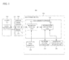
- FIG. 1 is a block diagram illustrating an information management system including an information management device.
- FIG. 1 also illustrates schematically functions performed by the operation of a software.
- An information management system 200 of FIG. 1 includes a client 210, a server 220 and a monitored device 230.
- the client 210 is connected to the server 220, and the server 220 is connected to the monitored device 230.
- the client 210 is a computer and includes a WWW (World Wide Web) browser 211.
- the server 220 is a computer and includes a WWW server 221.
- the WWW server 221 includes a CGI (Common Gateway Interface) 222 and a timer 223.
- the monitored device 230 includes a management software 231, a html (HyperText Markup Language) template 234, network system information 235 and hardware configuration information 236.
- the management software 231 includes a reception process unit 232 and an information collection unit 233.
- the management software 231 collects in real time the hardware configuration information 236 and the network system information 235 of the monitored device 230 through the CGI 222 of the WWW server 221 in response to a request from the WWW browser 211 of the client 210, and displays information as a monitoring screen on the WWW browser 211 of the client 210.
- the monitoring screen is a screen displaying information collected by the management software 231.
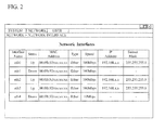
- FIG. 2 illustrates an example of the monitoring screen of a network interface card (NIC).
- NIC network interface card
- a Network Interfaces screen is displayed by selection of a Network Interfaces menu in a Network menu from the monitoring screen, and information on five NICs is displayed.
- the management software 231 includes the reception process unit 232 and the information collection unit 233.
- the WWW server 221 runs the CGI 222, and the CGI 222 requests the reception process unit 232 of the management software 231 to generate the WEB page.
- the reception process unit 232 requests the information collection unit 233 to collect information required for the requested WEB page.
- the information collection unit 233 collects the requested information in real time, and notifies the reception process unit 232 of the collected information.
- the reception process unit 232 which has received the information repeats an information collection request to the information collection unit 233 until all information required for the WEB page is collected.
- the reception process unit 232 When all the information is collected, the reception process unit 232 generates html information by combining the collected information and the html templates 234, and notifies the CGI 222 of the generated html information.
- the WWW server 221 terminates the CGI222 and notifies the WWW browser 211 of the html information.
- the CGI 222 of the WWW server 221 includes a timer 223.
- timeout occurs in the CGI 222.
- an administrator tunes up a timer value of the CGI 222 or induces operational attention to a user by cautionary statement to a manual.
- the reception process unit 232 requires time for the collection of information required for the requested WEB page, so that the CGI 222 is timeout and terminates before the reception process unit 232 notifies the WWW server 221 of the collected information. Therefore, the CGI 222 cannot return a response to the WWW browser. That is, the WWW browser 211 cannot display the WEB page. In this case, there is a means that changes the timer value of the CGI 222. However, only one timer value of the CGI 222 can be set to the WWW server 221, and influence by changing the timer value reaches also to another user who uses the WWW server 221. Therefore, the timer value of the CGI 222 cannot be changed easily.
- FIG. 3 is a block diagram illustrating an information management system including an information management device according to the present embodiment.
- FIG. 3 also illustrates schematically functions performed by the operation of a software.
- An information management system 100 of FIG. 3 includes a client 1, a server 2 (i.e., an information processing unit), and a monitored device (i.e., a information processing device) 3.
- the client 1 is connected to the server 2 via a network 4, and the server 2 is connected to the monitored device 3 via a network 5.
- the client 1 is a computer and includes a WWW (World Wide Web) browser 11 (i.e., a display unit).
- the server 2 is a computer and includes a WWW server 21.
- the WWW server 21 includes a CGI (Common Gateway Interface) 22 and a timer 23.
- the CGI 22 receives a response from the monitored device 3 and transmits the response to the WWW browser 11 of the client 1.
- time hereinafter referred to as "timeout period" beforehand set to the timer 23 has elapsed
- a reception process becomes timeout, and the CGI 22 cannot transmit the response from the monitored device 3 to the WWW browser 11.
- the monitored device 3 includes a management software 31, a html (HyperText Markup Language) template 36, a setting file 37, a progress file 38, network system information 39 and hardware configuration information 40.
- the management software 31 includes a reception process unit 32 (i.e., a first function, a first step, and a reception means), a cooperation unit 33 (i.e., a fourth function and a fourth step), process units 34 (i.e., a third function, a third step and a process means), and information collection unit 35 (i.e., a second function, a second step and an information collection means).
- the management software 31 receives a request from the WWW browser 11 via the CGI 22, collects the network system information 39 and the hardware configuration information 40, and causes the WWW browser 11 to display these information.
- the reception process unit 32 receives a request from the CGI 22 of the server 2, calls up one of the process units 34 through the cooperation unit 33.
- the cooperation unit 33 selects a process unit 34 corresponding to the information requested from the CGI 22 by referring to the setting file 37 using as a key the parameter received from the CGI 22, and calls up the selected process unit 34.
- the process unit 34 requests the information collection unit 35 to collect the information requested from the CGI 22, and notifies the reception process unit 32 of the progress of information collection by the information collection unit 35.
- the information collection unit 35 acquires the network system information 39 and the hardware configuration information 40 using a protocol such as Simple Network Management Protocol (SNMP).
- SNMP Simple Network Management Protocol
- the html template 36 is a template for displaying the network system information 39 and the hardware configuration information 40 in a html type.
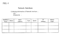
- FIG. 4 illustrates an example of the html template 36 for displaying information on a network interface in the html type.
- "ALL” is a column indicating the total number of network interfaces which are objects of information collection
- "FINISHED” is a column indicating the number of network interfaces in which the information collection has completed.
- "Interface Name” is a column indicating a name of the network interface.
- Status is a column indicating by “Up” that the network interface is in an enabled state, and by "Down” that the network interface is in a disabled state.
- MAC address is a column indicating a MAC address of the network interface.
- Type is a column indicating the standard of a network where the network interface is used.
- Speed is a column indicating a transfer rate of data which flows on the network interface.
- IP Address is a column indicating an IP address assigned to the network interface.
- Subnet Mask is a column that defines how many bits are used for the network address for identifying the network in the IP address.
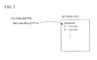
- the setting file 37 includes a list which associates parameters from the CGI 22 with the process units 34.
- FIG. 5 illustrates an example of the setting file 37.
- the parameter from the CGI 22 is "a1" or "a2”
- the process unit 34 corresponding to the parameter "a1” is an executable file which is "xxx.exe”
- the process unit corresponding to the parameter "a2” is an executable file which is "yyy.exe”.
- the progress file 38 includes progress information of the collection of the network system information 39 and the hardware configuration information 40, and concrete network system information 39 and concrete hardware configuration information 40 collected by the information collection unit 35.
- FIG. 6 illustrates an example of the progress file 38.
- the progress file 38 of FIG. 6 includes progress information (status) on the whole system indicating that collection of information on three network interfaces is completed among five network interfaces, and collected concrete information (no1, no2%) on each of the network interfaces.
- the network system information 39 is information on setting of the network which is acquired from an OS (Operating System), not indicated, included in the monitored device 3, for example.
- the hardware configuration information 40 is information on hardware (e.g. a system board, a memory, a hard disk drive (HDD), an I/O unit and so on) included in the monitored device 3.
- FIG. 7A is a diagram illustrating the hardware configuration of the server 2 and the monitored device 3.
- FIG. 7B is a diagram illustrating a variation example of the configuration of the server 2 and the monitored device 3.
- the monitored device 3 includes a system board 101 and an I/O (Input/Output) unit 102 that inputs and outputs information from/to the outside of the monitored device 3.
- a CPU 103 that controls the whole monitored device 3 and a memory 104 that functions as a working area and stores a given program are mounted on the system board 101.
- a hard disk drive (HDD) 105 that stores the OS and the management software 31 and a network interface 106 are connected to the system board 101.
- the I/O unit 102 is connected to the system board 101.
- the CPU 103 executes the management software 31, so that the reception process unit 32, the cooperation unit 33, the process units 34 and the information collection unit 35 included in the management software 31 are achieved.
- the main board 2a may achieve the function of the server 2 and each of the partitions 3a and 3b may achieve the function of the monitored device 3, for example.
- the server 2 and one or more monitored device 3 can be achieved by the single computer.
- the system board 101 of FIG. 7B mounts the CPU 103 and the memory 104, and the hard disk drive (HDD) 105, the I/O unit 102 and the network interface 106, not indicated, are connected to the system board 101.
- HDD hard disk drive
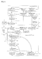
- FIG. 8 is a flowchart illustrating a process performed with the information management system.
- the WWW browser 11 requests the WEB page from the WWW server 21 (step S1).
- the WWW server 21 runs the CGI 22 corresponding to the requested WEB page and outputs the request of the WEB page to the reception process unit 32 (step S2).
- the reception process unit 32 receives the request of the WEB page from the WWW server 21 (step S3).
- the cooperation unit 33 selects the process unit 34 corresponding to the requested WEB page by referring to the setting file 37 using the parameter included in the request from the CGI 22 as a key, and calls up the selected process unit (step S4).
- the process unit 34 called up by the cooperation unit 33 checks the progress of collection of information required for the monitoring of the monitored device 3 with reference to the progress file 38 (step S5).
- the information required for the monitoring of the monitored device 3 is information such as "Interface Name”, "Status”, "MAC Address”, “Type”, “Speed”, “IP Address” and "Subnet Mask” when the network interface in the monitored device 3 is monitored, for example.
- the process unit 34 When there is not the progress file 38, the process unit 34 generates an empty file newly.
- the process unit 34 When the information required for the monitoring of the monitored device 3 is not collected at all (uncollected of step S6), the process unit 34 requests the information collection unit 35 to collect the total number of pieces of information required for the monitoring of the monitored device 3 (step S7).
- the progress html which the process unit 34 generates requires five sets of information on the network interfaces, in order to indicate the progress.
- the process unit 34 knows the total number of pieces of required information on the network interface beforehand, the total number of pieces of required information is not used, so that the process of step S7 can be omitted.
- the information collection unit 35 counts only the number of pieces of information to be collected in response to a request from the process unit 34 in step S7, and notifies the process unit 34 of the number of pieces of information (step S8).
- the information collection unit 35 notifies the process unit 34 that the information on the network interface to be collected is five sets.
- the process unit 34 writes the counted value notified from the information collection unit 35, i.e., the total number of pieces of information required for the monitoring of the monitored device 3, in the progress file 38 (step S7).
- the process unit 34 After the total number of pieces of information to be collected is notified from the information collection unit 35, the process unit 34 generates a thread (step S9) and suitably checks the progress of information collection (step S5).
- the process unit 34 waits for only a time period shorter than the timeout period of the CGI 22.
- the process unit 34 starts counting the waiting time.
- the timeout period of the CGI 22 may be registered into the process unit 34 beforehand, or the timeout period of the CGI 22 may be included in the parameter from the CGI 22 and the process unit 34 may be informed of the timeout period of the CGI 22.
- the process unit 34 can send back a result html without sending back the progress html before the timeout period of the CGI 22 elapses.
- the process unit 34 suitably checks the progress of information collection after waiting for only the time period shorter than the timeout period of the CGI 22 (step S5), the similar waiting is performed also when the information required for the monitoring of the monitored device 3 is under collection (under collection of step S6) and also when all the information have been collected (collection completion of Step S6).
- the control unit 34 continuously performs check of progress (step S5), generation and transmission of the progress html described later (step S14), and generation and transmission of the result html described later (step S 17), in timing before the CGI 22 causes the timeout.
- the control unit 34 prevents the CGI 22 from causing the timeout during the time period from the request of the WEB page (step S1) to the completion of information collection.
- the process unit 34 requests the information collection unit 35 to collect the information required for the monitoring of the monitored device 3 from the thread generated in step S9 (step S10).
- the information collection unit 35 receives the request from the process unit 34 of step S10, collects the information required for the monitoring of the monitored device 3, and transmits the collected information to the process unit 34 (step S11).
- the thread of the process unit 34 acquires one piece of information from the information collection unit 35, the thread of the process unit 34 updates the progress file 38 (step S12).
- the process unit 34 terminates (or deletes) the thread (step S 13).
- step S5 check of the progress of the information collection (step S5), request of the information collection (step S10), the information collection (step S11) and update of the progress file 38 (step S12) are performed after the process unit 34 generates the thread (step S9).
- step S5 and the processes of steps S10 to S12 are performed independently. That is, the information collection and check of the progress proceed independently.
- the process unit 34 When the information required for the monitoring of the monitored device 3 is under collection after the progress of step S5 is checked (under collection of step S6), the process unit 34 generates a html (i.e., progress html) indicating that the information is under collection, based on the progress file 38, and transmits the progress html to the WWW server 21 via the reception process unit 32, during the time period shorter than the timeout period of the CGI 22 (step S14).
- the progress html is generated on the basis of a generated time of the thread, for each constant period shorter than the timeout period of the CGI 22, and is transmitted to the WWW server 21.
- the process unit 34 when generating the progress html, the process unit 34 gives a description of "refresh" to the progress html as a meta tag.
- the "refresh" of the meta tag can specify a time for making the WWW browser 11 retry, and the address of the CGI 22. Therefore, the process unit 34 generates the progress html that specifies the time for making the WWW browser 11 retry, and the address of the CGI 22, transmits the generated progress html to the WWW browser 11, and hence causes the WWW browser 11 to automatically re-request the process of Step S1 within the time period shorter than the timeout period.
- FIG. 9 illustrates an example of a screen displayed using the WWW browser 11 which has received the progress html.
- the progress of the information collection and the collected information such as a progress bar and an intermediate result of the information collection for example, are included in the screen displayed using the WWW browser 11 which has received the progress html.
- the WWW server 21 When receiving the progress html from the process unit 34, the WWW server 21 terminates the CGI 22, and transmits the progress html received from the process unit 34, to the WWW browser 11 (step S15).
- the WWW browser 11 receives the progress html, and displays a corresponding screen (step S16).
- the WWW browser 11 performs the process of step S1 again after a given time period (e.g. 2 seconds) according to the time specified by the "refresh" of the meta tag embedded in the progress html.
- the process unit 34 collects the information using the thread generated in step S9 in parallel with generating the progress html and causing the WWW browser 11 to display the progress html via the WWW server 21. Thereby, the required information can be collected and the progress information can be generated and displayed in a short time.
- step S6 When all the information required for the monitoring of the monitored device 3 is collected after the progress of step S5 is checked (collection completion of step S6), the process unit 34 generates the result html indicating a WEB page to be displayed and including a result of the information collection, and transmits the result html to the WWW server 21 via the reception process unit 32, during the time period shorter than the timeout period of the CGI 22 (step S 17).
- the WWW server 21 terminates the CGI 22 and transmits the result html received from the process unit 34, to the WWW browser 11 (step S18).
- the WWW browser 11 receives and displays the result html (step S19). Since the "refresh" of the meta tag is not embedded in the result html, the process is terminated at step S 19.
- the reception process unit 32 receives a request of information from the WWW server 21 having the CGI, and the information collection unit 35 collects the information corresponding to the request.
- the process unit 34 requests the information collection unit 35 to collect the information corresponding to the request, in response to the request of the information.
- the process unit 34 generates the progress html indicating the progress of the information collection and the collected information, and causes the WWW browser 11 to display the progress html via the WWW server 21, during the time period shorter than the timeout period of the CGI. Therefore, the disconnection of communication with the WWW server 21 can be prevented, and the user can check the progress of process in real time.
- the process unit 34 when the process unit 34 generates the progress html, the process unit 34 embeds into the progress html the meta tag in which the WWW server 21 requests the WEB page again. Therefore, the user can check the progress of process continuously, without paying particular attention to a request again.
- the process unit 34 is decided by the CGI parameter and the setting file which are sent to CGI22, and generates the progress html and the result html. Therefore, also when a WEB page is added newly, it is possible to incorporate a unique process for each WEB page, without adding change to the CGI 22 or the reception process unit 32.
- the process unit 34 generates the thread (step S9), and requests the information collection unit 35 to collect the information required for the monitoring of the monitored device 3 from the thread generated in step S9 (step S10).
- the process unit 34 may generate a child process, and request the information collection unit 35 to collect the information required for the monitoring of the monitored device 3 from the generated child process.
- the child process is a subprogram called up from a main program (parent process) which the control unit 34 runs.
- a non-transitory recording medium on which the software program for realizing the functions of the monitored device 3 is recorded may be supplied to the monitored device 3, and the CPU 103 may read and execute the program recorded on the non-transitory recording medium.
- the non-transitory recording medium for providing the program may be a CD-ROM (Compact Disk Read Only Memory), a DVD (Digital Versatile Disk), a Blu-ray Disk, SD (Secure Digital) card or the like, for example.
- the CPU 103 of the monitored device 3 may execute a software program for realizing the functions of the monitored device 3, so as to achieve the same effects as those of the above-described embodiments.
Landscapes
- Engineering & Computer Science (AREA)
- Computer Networks & Wireless Communication (AREA)
- Signal Processing (AREA)
- Computer Security & Cryptography (AREA)
- Environmental & Geological Engineering (AREA)
- Debugging And Monitoring (AREA)
- Information Transfer Between Computers (AREA)
- Computer And Data Communications (AREA)
Abstract
A monitored device (3) as an information management device includes: a reception process unit (32) that receives a request of information from a WWW server (21) having a CGI; an information collection unit (35) that collects the information corresponding to the request; and a process unit (34) that requests the information collection unit (35) to collect the information corresponding to the request in response to the request of information, and during a time period shorter than a timeout period of the CGI, generates a progress html indicating progress of collection of the information and corrected information, and causes a WWW browser (11) to display the progress html on via the WWW server (21).
Description
- The present invention relates to a program, an information management method and an information management device.
- There is known a server device that performs a given process based on a request from a communication terminal (See Patent Document 1). The server device transmits an e-mail including a URL address for acquiring a result of the performed process to the communication terminal before transmitting the result of the performed process to the communication terminal.
-
- Patent Document 1: Japanese Laid-open Patent Publication No.
2004-127278 - In the technique of
Patent Document 1, when a user accesses a page indicated by the URL address, the user can check the status of the process or the result of the process in timing of the access. However, the user cannot check the progress of the process in real time. - In view of the above described problem, it is an object to provide a program, an information management method and an information management device that can prevent disconnection of communication, and enable a user to check progress of a process.
- In order to achieve the above-mentioned object, a program for causing a computer to execute a process, includes: receiving a request of information from an information process unit having a CGI, as a first function; collecting the information corresponding to the request, as a second function; and requesting the second function to collect the information corresponding to the request in response to the request of information, and during a time period shorter than a timeout period of the CGI, generating progress information indicating progress of collection of the information and corrected information, and causing a display unit to display the progress information, as a third function.
- An information management method for causing a computer to execute a process, includes: receiving a request of information from an information process unit having a CGI, as a first step; collecting the information corresponding to the request, as a second step; and requesting the second step to collect the information corresponding to the request in response to the request of information, and during a time period shorter than a timeout period of the CGI, generating progress information indicating progress of collection of the information and corrected information, and causing a display unit to display the progress information, as a third step.
- An information management device, includes: a reception unit that receives a request of information from an information process unit having a CGI; an information collection unit that collects the information corresponding to the request; and a process unit that requests the information collection unit to collect the information corresponding to the request in response to the request of information, and during a time period shorter than a timeout period of the CGI, generates progress information indicating progress of collection of the information and corrected information, and causes a display unit to display the progress information.
- A program, an information management method and an information management device described herein can prevent disconnection of communication, and enable a user to check progress of a process in real time.
-
-
FIG. 1 is a block diagram illustrating an information management system including an information management device according to a reference example; -
FIG. 2 is a diagram illustrating an example of a monitoring screen of a network interface card (NIC); -
FIG. 3 is a block diagram illustrating an information management system including an information management device according to a present embodiment; -
FIG. 4 is a diagram illustrating an example of a html template; -
FIG. 5 is a diagram illustrating an example of a setting file; -
FIG. 6 is a diagram illustrating an example of a progress file; -
FIG. 7A is a diagram illustrating a hardware configuration of a monitored device; -
FIG. 7B is a diagram illustrating a variation example of the configuration of a server and the monitored device; -
FIG. 8 is a flowchart illustrating a process performed with the information management system; and -
FIG. 9 is a diagram illustrating an example of a screen displayed using a WWW browser which has received the progress html. - (comparative example)
FIG. 1 is a block diagram illustrating an information management system including an information management device. Here,FIG. 1 also illustrates schematically functions performed by the operation of a software. Aninformation management system 200 ofFIG. 1 includes aclient 210, aserver 220 and a monitoreddevice 230. Theclient 210 is connected to theserver 220, and theserver 220 is connected to the monitoreddevice 230. - The
client 210 is a computer and includes a WWW (World Wide Web)browser 211. Theserver 220 is a computer and includes aWWW server 221. Then, theWWW server 221 includes a CGI (Common Gateway Interface) 222 and atimer 223. The monitoreddevice 230 includes amanagement software 231, a html (HyperText Markup Language)template 234,network system information 235 andhardware configuration information 236. Themanagement software 231 includes areception process unit 232 and aninformation collection unit 233. Themanagement software 231 collects in real time thehardware configuration information 236 and thenetwork system information 235 of the monitoreddevice 230 through theCGI 222 of theWWW server 221 in response to a request from theWWW browser 211 of theclient 210, and displays information as a monitoring screen on theWWW browser 211 of theclient 210. Here, the monitoring screen is a screen displaying information collected by themanagement software 231.FIG. 2 illustrates an example of the monitoring screen of a network interface card (NIC). In this example, a Network Interfaces screen is displayed by selection of a Network Interfaces menu in a Network menu from the monitoring screen, and information on five NICs is displayed. - The
management software 231 includes thereception process unit 232 and theinformation collection unit 233. When a request of a WEB page is transmitted from theWWW browser 211 to theWWW server 221 of theclient 210, theWWW server 221 runs theCGI 222, and theCGI 222 requests thereception process unit 232 of themanagement software 231 to generate the WEB page. Thereception process unit 232 requests theinformation collection unit 233 to collect information required for the requested WEB page. Theinformation collection unit 233 collects the requested information in real time, and notifies thereception process unit 232 of the collected information. Thereception process unit 232 which has received the information repeats an information collection request to theinformation collection unit 233 until all information required for the WEB page is collected. When all the information is collected, thereception process unit 232 generates html information by combining the collected information and thehtml templates 234, and notifies theCGI 222 of the generated html information. TheWWW server 221 terminates the CGI222 and notifies theWWW browser 211 of the html information. - Here, the
CGI 222 of theWWW server 221 includes atimer 223. When the collection of information takes time, timeout occurs in theCGI 222. In such a case, an administrator tunes up a timer value of theCGI 222 or induces operational attention to a user by cautionary statement to a manual. - When there is a great deal of information required for the requested WEB page in the
management software 231, thereception process unit 232 requires time for the collection of information required for the requested WEB page, so that theCGI 222 is timeout and terminates before thereception process unit 232 notifies theWWW server 221 of the collected information. Therefore, theCGI 222 cannot return a response to the WWW browser. That is, theWWW browser 211 cannot display the WEB page. In this case, there is a means that changes the timer value of theCGI 222. However, only one timer value of theCGI 222 can be set to theWWW server 221, and influence by changing the timer value reaches also to another user who uses theWWW server 221. Therefore, the timer value of theCGI 222 cannot be changed easily. - (Embodiment) A description will be given of the present embodiment, with reference to
FIGs. 3 to 9 . -
FIG. 3 is a block diagram illustrating an information management system including an information management device according to the present embodiment. Here,FIG. 3 also illustrates schematically functions performed by the operation of a software. - An
information management system 100 ofFIG. 3 includes aclient 1, a server 2 (i.e., an information processing unit), and a monitored device (i.e., a information processing device) 3. Theclient 1 is connected to theserver 2 via anetwork 4, and theserver 2 is connected to the monitoreddevice 3 via anetwork 5. - The
client 1 is a computer and includes a WWW (World Wide Web) browser 11 (i.e., a display unit). Theserver 2 is a computer and includes aWWW server 21. Then, theWWW server 21 includes a CGI (Common Gateway Interface) 22 and atimer 23. TheCGI 22 receives a response from the monitoreddevice 3 and transmits the response to theWWW browser 11 of theclient 1. When theCGI 22 cannot receive the response from the monitoreddevice 3 even if time (hereinafter referred to as "timeout period") beforehand set to thetimer 23 has elapsed, a reception process becomes timeout, and theCGI 22 cannot transmit the response from the monitoreddevice 3 to theWWW browser 11. - The monitored
device 3 includes amanagement software 31, a html (HyperText Markup Language)template 36, a settingfile 37, aprogress file 38,network system information 39 andhardware configuration information 40. Themanagement software 31 includes a reception process unit 32 (i.e., a first function, a first step, and a reception means), a cooperation unit 33 (i.e., a fourth function and a fourth step), process units 34 (i.e., a third function, a third step and a process means), and information collection unit 35 (i.e., a second function, a second step and an information collection means). Themanagement software 31 receives a request from theWWW browser 11 via theCGI 22, collects thenetwork system information 39 and thehardware configuration information 40, and causes theWWW browser 11 to display these information. - The
reception process unit 32 receives a request from theCGI 22 of theserver 2, calls up one of theprocess units 34 through thecooperation unit 33. Thecooperation unit 33 selects aprocess unit 34 corresponding to the information requested from theCGI 22 by referring to thesetting file 37 using as a key the parameter received from theCGI 22, and calls up the selectedprocess unit 34. Theprocess unit 34 requests theinformation collection unit 35 to collect the information requested from theCGI 22, and notifies thereception process unit 32 of the progress of information collection by theinformation collection unit 35. Theinformation collection unit 35 acquires thenetwork system information 39 and thehardware configuration information 40 using a protocol such as Simple Network Management Protocol (SNMP). - The
html template 36 is a template for displaying thenetwork system information 39 and thehardware configuration information 40 in a html type. For example,FIG. 4 illustrates an example of thehtml template 36 for displaying information on a network interface in the html type. InFIG. 4 , "ALL" is a column indicating the total number of network interfaces which are objects of information collection, and "FINISHED" is a column indicating the number of network interfaces in which the information collection has completed. "Interface Name" is a column indicating a name of the network interface. "Status" is a column indicating by "Up" that the network interface is in an enabled state, and by "Down" that the network interface is in a disabled state. "MAC address" is a column indicating a MAC address of the network interface. "Type" is a column indicating the standard of a network where the network interface is used. "Speed" is a column indicating a transfer rate of data which flows on the network interface. "IP Address" is a column indicating an IP address assigned to the network interface. "Subnet Mask" is a column that defines how many bits are used for the network address for identifying the network in the IP address. - The setting
file 37 includes a list which associates parameters from theCGI 22 with theprocess units 34.FIG. 5 illustrates an example of the settingfile 37. InFIG. 5 , the parameter from theCGI 22 is "a1" or "a2", theprocess unit 34 corresponding to the parameter "a1" is an executable file which is "xxx.exe", and the process unit corresponding to the parameter "a2" is an executable file which is "yyy.exe". When a CGI parameter "http://aaa.bbb.cgi?fl=a1" is received from theCGI 22, theprocess unit 34 associated with the parameter "a1", i.e., "xxx.exe" is referred to from the settingfile 37. - The
progress file 38 includes progress information of the collection of thenetwork system information 39 and thehardware configuration information 40, and concretenetwork system information 39 and concretehardware configuration information 40 collected by theinformation collection unit 35.FIG. 6 illustrates an example of theprogress file 38. Theprogress file 38 ofFIG. 6 includes progress information (status) on the whole system indicating that collection of information on three network interfaces is completed among five network interfaces, and collected concrete information (no1, no2...) on each of the network interfaces. - The
network system information 39 is information on setting of the network which is acquired from an OS (Operating System), not indicated, included in the monitoreddevice 3, for example. Thehardware configuration information 40 is information on hardware (e.g. a system board, a memory, a hard disk drive (HDD), an I/O unit and so on) included in the monitoreddevice 3. -
FIG. 7A is a diagram illustrating the hardware configuration of theserver 2 and the monitoreddevice 3.FIG. 7B is a diagram illustrating a variation example of the configuration of theserver 2 and the monitoreddevice 3. - As illustrated in
FIG. 7A , the monitoreddevice 3 includes asystem board 101 and an I/O (Input/Output)unit 102 that inputs and outputs information from/to the outside of the monitoreddevice 3. ACPU 103 that controls the whole monitoreddevice 3 and amemory 104 that functions as a working area and stores a given program are mounted on thesystem board 101. A hard disk drive (HDD) 105 that stores the OS and themanagement software 31 and anetwork interface 106 are connected to thesystem board 101. In addition, the I/O unit 102 is connected to thesystem board 101. TheCPU 103 executes themanagement software 31, so that thereception process unit 32, thecooperation unit 33, theprocess units 34 and theinformation collection unit 35 included in themanagement software 31 are achieved. - When a single computer has a
main board 2a which includes theWWW server 21, and a plurality ofpartitions system board 101 and the I/O unit 102, as illustrated inFIG. 7B , themain board 2a may achieve the function of theserver 2 and each of thepartitions device 3, for example. Thus, theserver 2 and one or moremonitored device 3 can be achieved by the single computer. - Here, as is the case with
FIG. 7A , thesystem board 101 ofFIG. 7B mounts theCPU 103 and thememory 104, and the hard disk drive (HDD) 105, the I/O unit 102 and thenetwork interface 106, not indicated, are connected to thesystem board 101. -
FIG. 8 is a flowchart illustrating a process performed with the information management system. - First, the
WWW browser 11 requests the WEB page from the WWW server 21 (step S1). TheWWW server 21 runs theCGI 22 corresponding to the requested WEB page and outputs the request of the WEB page to the reception process unit 32 (step S2). Thereception process unit 32 receives the request of the WEB page from the WWW server 21 (step S3). Thecooperation unit 33 selects theprocess unit 34 corresponding to the requested WEB page by referring to thesetting file 37 using the parameter included in the request from theCGI 22 as a key, and calls up the selected process unit (step S4). - The
process unit 34 called up by thecooperation unit 33 checks the progress of collection of information required for the monitoring of the monitoreddevice 3 with reference to the progress file 38 (step S5). The information required for the monitoring of the monitoreddevice 3 is information such as "Interface Name", "Status", "MAC Address", "Type", "Speed", "IP Address" and "Subnet Mask" when the network interface in the monitoreddevice 3 is monitored, for example. When there is not theprogress file 38, theprocess unit 34 generates an empty file newly. - When the information required for the monitoring of the monitored
device 3 is not collected at all (uncollected of step S6), theprocess unit 34 requests theinformation collection unit 35 to collect the total number of pieces of information required for the monitoring of the monitored device 3 (step S7). Here, when five network interfaces are monitored for example, the progress html which theprocess unit 34 generates requires five sets of information on the network interfaces, in order to indicate the progress. However, when theprocess unit 34 knows the total number of pieces of required information on the network interface beforehand, the total number of pieces of required information is not used, so that the process of step S7 can be omitted. - The
information collection unit 35 counts only the number of pieces of information to be collected in response to a request from theprocess unit 34 in step S7, and notifies theprocess unit 34 of the number of pieces of information (step S8). When the network interface is monitored and the monitoreddevice 3 has five network interfaces, for example, theinformation collection unit 35 notifies theprocess unit 34 that the information on the network interface to be collected is five sets. Then, theprocess unit 34 writes the counted value notified from theinformation collection unit 35, i.e., the total number of pieces of information required for the monitoring of the monitoreddevice 3, in the progress file 38 (step S7). After the total number of pieces of information to be collected is notified from theinformation collection unit 35, theprocess unit 34 generates a thread (step S9) and suitably checks the progress of information collection (step S5). Here, before returning to step S5 from step S9, theprocess unit 34 waits for only a time period shorter than the timeout period of theCGI 22. When theprocess unit 34 is called up by thecooperation unit 33, theprocess unit 34 starts counting the waiting time. The timeout period of theCGI 22 may be registered into theprocess unit 34 beforehand, or the timeout period of theCGI 22 may be included in the parameter from theCGI 22 and theprocess unit 34 may be informed of the timeout period of theCGI 22. When there is little information to be collected, the collection of the information is completed in time shorter than the waiting time of theprocess unit 34. Therefore, theprocess unit 34 can send back a result html without sending back the progress html before the timeout period of theCGI 22 elapses. - Although the
process unit 34 suitably checks the progress of information collection after waiting for only the time period shorter than the timeout period of the CGI 22 (step S5), the similar waiting is performed also when the information required for the monitoring of the monitoreddevice 3 is under collection (under collection of step S6) and also when all the information have been collected (collection completion of Step S6). This is because, during a time period from the request of the WEB page (step S1) to the completion of information collection, thecontrol unit 34 continuously performs check of progress (step S5), generation and transmission of the progress html described later (step S14), and generation and transmission of the result html described later (step S 17), in timing before theCGI 22 causes the timeout. Thus, thecontrol unit 34 prevents theCGI 22 from causing the timeout during the time period from the request of the WEB page (step S1) to the completion of information collection. - The
process unit 34 requests theinformation collection unit 35 to collect the information required for the monitoring of the monitoreddevice 3 from the thread generated in step S9 (step S10). Theinformation collection unit 35 receives the request from theprocess unit 34 of step S10, collects the information required for the monitoring of the monitoreddevice 3, and transmits the collected information to the process unit 34 (step S11). Whenever the thread of theprocess unit 34 acquires one piece of information from theinformation collection unit 35, the thread of theprocess unit 34 updates the progress file 38 (step S12). When the collection of the information required for the monitoring of the monitoreddevice 3 is completed, theprocess unit 34 terminates (or deletes) the thread (step S 13). As described above, check of the progress of the information collection (step S5), request of the information collection (step S10), the information collection (step S11) and update of the progress file 38 (step S12) are performed after theprocess unit 34 generates the thread (step S9). Here, the process of step S5 and the processes of steps S10 to S12 are performed independently. That is, the information collection and check of the progress proceed independently. - When the information required for the monitoring of the monitored
device 3 is under collection after the progress of step S5 is checked (under collection of step S6), theprocess unit 34 generates a html (i.e., progress html) indicating that the information is under collection, based on theprogress file 38, and transmits the progress html to theWWW server 21 via thereception process unit 32, during the time period shorter than the timeout period of the CGI 22 (step S14). The progress html is generated on the basis of a generated time of the thread, for each constant period shorter than the timeout period of theCGI 22, and is transmitted to theWWW server 21. Here, when generating the progress html, theprocess unit 34 gives a description of "refresh" to the progress html as a meta tag. The "refresh" of the meta tag can specify a time for making theWWW browser 11 retry, and the address of theCGI 22. Therefore, theprocess unit 34 generates the progress html that specifies the time for making theWWW browser 11 retry, and the address of theCGI 22, transmits the generated progress html to theWWW browser 11, and hence causes theWWW browser 11 to automatically re-request the process of Step S1 within the time period shorter than the timeout period.FIG. 9 illustrates an example of a screen displayed using theWWW browser 11 which has received the progress html. The progress of the information collection and the collected information, such as a progress bar and an intermediate result of the information collection for example, are included in the screen displayed using theWWW browser 11 which has received the progress html. - When receiving the progress html from the
process unit 34, theWWW server 21 terminates theCGI 22, and transmits the progress html received from theprocess unit 34, to the WWW browser 11 (step S15). TheWWW browser 11 receives the progress html, and displays a corresponding screen (step S16). Moreover, theWWW browser 11 performs the process of step S1 again after a given time period (e.g. 2 seconds) according to the time specified by the "refresh" of the meta tag embedded in the progress html. - Here, when the information required for the monitoring of the monitored
device 3 is under collection (under collection of step S6), theprocess unit 34 collects the information using the thread generated in step S9 in parallel with generating the progress html and causing theWWW browser 11 to display the progress html via theWWW server 21. Thereby, the required information can be collected and the progress information can be generated and displayed in a short time. - When all the information required for the monitoring of the monitored
device 3 is collected after the progress of step S5 is checked (collection completion of step S6), theprocess unit 34 generates the result html indicating a WEB page to be displayed and including a result of the information collection, and transmits the result html to theWWW server 21 via thereception process unit 32, during the time period shorter than the timeout period of the CGI 22 (step S 17). TheWWW server 21 terminates theCGI 22 and transmits the result html received from theprocess unit 34, to the WWW browser 11 (step S18). TheWWW browser 11 receives and displays the result html (step S19). Since the "refresh" of the meta tag is not embedded in the result html, the process is terminated atstep S 19. - As described above, according to the embodiment, the
reception process unit 32 receives a request of information from theWWW server 21 having the CGI, and theinformation collection unit 35 collects the information corresponding to the request. Theprocess unit 34 requests theinformation collection unit 35 to collect the information corresponding to the request, in response to the request of the information. Moreover, theprocess unit 34 generates the progress html indicating the progress of the information collection and the collected information, and causes theWWW browser 11 to display the progress html via theWWW server 21, during the time period shorter than the timeout period of the CGI. Therefore, the disconnection of communication with theWWW server 21 can be prevented, and the user can check the progress of process in real time. - In addition, when the
process unit 34 generates the progress html, theprocess unit 34 embeds into the progress html the meta tag in which theWWW server 21 requests the WEB page again. Therefore, the user can check the progress of process continuously, without paying particular attention to a request again. - Further, the
process unit 34 is decided by the CGI parameter and the setting file which are sent to CGI22, and generates the progress html and the result html. Therefore, also when a WEB page is added newly, it is possible to incorporate a unique process for each WEB page, without adding change to theCGI 22 or thereception process unit 32. - In the above-mentioned embodiment, the
process unit 34 generates the thread (step S9), and requests theinformation collection unit 35 to collect the information required for the monitoring of the monitoreddevice 3 from the thread generated in step S9 (step S10). Alternatively, theprocess unit 34 may generate a child process, and request theinformation collection unit 35 to collect the information required for the monitoring of the monitoreddevice 3 from the generated child process. Here, the child process is a subprogram called up from a main program (parent process) which thecontrol unit 34 runs. - A non-transitory recording medium on which the software program for realizing the functions of the monitored
device 3 is recorded may be supplied to the monitoreddevice 3, and theCPU 103 may read and execute the program recorded on the non-transitory recording medium. In this manner, the same effects as those of the above-mentioned embodiments can be achieved. The non-transitory recording medium for providing the program may be a CD-ROM (Compact Disk Read Only Memory), a DVD (Digital Versatile Disk), a Blu-ray Disk, SD (Secure Digital) card or the like, for example. - Alternatively, the
CPU 103 of the monitoreddevice 3 may execute a software program for realizing the functions of the monitoreddevice 3, so as to achieve the same effects as those of the above-described embodiments. - 1 client, 2 server, 3 monitored device, 11 WWW browser, 21 WWW server, 22 CGI, 23 timer, 31 management software, 32 reception process unit , 33 cooperation unit, 34 process unit, 35 information collection unit, 36 html template, 37 setting file, 38 progress file, 39 network system information, 40 hardware configuration information
Claims (13)
- A program for causing a computer to execute a process, characterized by comprising:receiving a request of information from an information process unit having a CGI, as a first function;collecting the information corresponding to the request, as a second function; andrequesting the second function to collect the information corresponding to the request in response to the request of information, and during a time period shorter than a timeout period of the CGI, generating progress information indicating progress of collection of the information and corrected information, and causing a display unit to display the progress information, as a third function.
- The program as claimed in claim 1, characterized in that when generating the progress information, the third function embeds data in which the information process unit requests the information again, into the progress information, during the time period shorter than the timeout period of the CGI.
- The program as claimed in claim 1 or 2, characterized in that the third function generates a thread or a process that collects the information corresponding to the request from the second function, and generates the progress information and causes the display unit to display the progress information in parallel with collecting the information by the thread or the process.
- The program as claimed in any one of claims 1 to 3, characterized in that when collection of the information is completed, the third function generates result information indicating a result of collection of the information and causes the display unit to display the result information.
- The program as claimed in any one of claims 1 to 4, characterized in that the program includes a plurality of third functions, and the program comprises a fourth function that selects a third function corresponding to the requested information from among the plurality of third functions.
- The program as claimed in any one of claims 1 to 5, characterized in that the information requested from the information process unit is information on setting of a network and information on hardware.
- An information management method for causing a computer to execute a process, characterized by comprising:receiving a request of information from an information process unit having a CGI, as a first step;collecting the information corresponding to the request, as a second step; andrequesting the second step to collect the information corresponding to the request in response to the request of information, and during a time period shorter than a timeout period of the CGI, generating progress information indicating progress of collection of the information and corrected information, and causing a display unit to display the progress information, as a third step.
- The information management method as claimed in claim 7, characterized in that when generating the progress information, the third step embeds data in which the information process unit requests the information again, into the progress information, during the time period shorter than the timeout period of the CGI.
- The information management method as claimed in claim 7 or 8, characterized in that the third step generates a thread or a process that collects the information corresponding to the request from the second step, and generates the progress information and causes the display unit to display the progress information in parallel with collecting the information by the thread or the process.
- The information management method as claimed in any one of claim 7 to 9, characterized in that when collection of the information is completed, the third step generates result information indicating a result of collection of the information and causes the display unit to display the result information.
- The information management method as claimed in any one of claim 7 to 10, characterized in that the information management method includes a plurality of third steps, and the information management method comprises selecting a third step corresponding to the requested information from among the plurality of third steps.
- The information management method as claimed in any one of claim 7 to 11, characterized in that the information requested from the information process unit is information on setting of a network and information on hardware.
- An information management device, characterized by comprising:a reception unit that receives a request of information from an information, process unit having a CGI;an information collection unit that collects the information corresponding to the request; anda process unit that requests the information collection unit to collect the information corresponding to the request in response to the request of information, and during a time period shorter than a timeout period of the CGI, generates progress information indicating progress of collection of the information and corrected information, and causes a display unit to display the progress information.
Applications Claiming Priority (1)
| Application Number | Priority Date | Filing Date | Title |
|---|---|---|---|
| PCT/JP2010/052775 WO2011104820A1 (en) | 2010-02-23 | 2010-02-23 | Program, data management method, and data management device |
Publications (2)
| Publication Number | Publication Date |
|---|---|
| EP2541424A1 true EP2541424A1 (en) | 2013-01-02 |
| EP2541424A4 EP2541424A4 (en) | 2017-10-04 |
Family
ID=44506267
Family Applications (1)
| Application Number | Title | Priority Date | Filing Date |
|---|---|---|---|
| EP10846487.6A Withdrawn EP2541424A4 (en) | 2010-02-23 | 2010-02-23 | Program, data management method, and data management device |
Country Status (4)
| Country | Link |
|---|---|
| US (1) | US9516148B2 (en) |
| EP (1) | EP2541424A4 (en) |
| JP (1) | JP5737279B2 (en) |
| WO (1) | WO2011104820A1 (en) |
Families Citing this family (1)
| Publication number | Priority date | Publication date | Assignee | Title |
|---|---|---|---|---|
| CN109257424A (en) * | 2018-09-18 | 2019-01-22 | 图普科技(广州)有限公司 | The processing method and monitor supervision platform of monitoring data |
Family Cites Families (15)
| Publication number | Priority date | Publication date | Assignee | Title |
|---|---|---|---|---|
| US6189030B1 (en) * | 1996-02-21 | 2001-02-13 | Infoseek Corporation | Method and apparatus for redirection of server external hyper-link references |
| US6938257B1 (en) * | 1997-07-17 | 2005-08-30 | International Business Machines Corporation | Apparatus and method to provide persistence for application interfaces |
| US6308205B1 (en) * | 1998-10-22 | 2001-10-23 | Canon Kabushiki Kaisha | Browser-based network management allowing administrators to use web browser on user's workstation to view and update configuration of network devices |
| JP3346312B2 (en) * | 1999-01-08 | 2002-11-18 | 日本電気株式会社 | Network management system |
| JP3834452B2 (en) * | 1999-04-01 | 2006-10-18 | セイコーエプソン株式会社 | Device management system, management server, and computer-readable recording medium |
| JP2001051925A (en) * | 1999-08-09 | 2001-02-23 | Nippon System Development Co Ltd | Method and system for collecting browsing information on network, and storage medium |
| US7003798B2 (en) * | 2000-10-20 | 2006-02-21 | Canon Kabushiki Kaisha | System for operating device from remote location and apparatus for use in the system |
| WO2003001389A1 (en) * | 2001-06-20 | 2003-01-03 | Matsushita Electric Industrial Co., Ltd. | Network system and agent server |
| JP2003157184A (en) * | 2001-11-22 | 2003-05-30 | Nec Soft Ltd | Method, system, and program for monitoring program execution |
| JP3725087B2 (en) * | 2002-04-10 | 2005-12-07 | 株式会社東芝 | Knowledge information collecting system and knowledge information collecting method |
| US7409431B2 (en) | 2002-09-13 | 2008-08-05 | Canon Kabushiki Kaisha | Server apparatus, communications method, program for making computer execute the communications method, and computer-readable storage medium containing the program |
| JP2004127278A (en) | 2002-09-13 | 2004-04-22 | Canon Inc | Server device, communication method, and program for causing computer device to execute communication method, and storage medium storing computer-readable program |
| US7440809B2 (en) * | 2004-07-14 | 2008-10-21 | York International Corporation | HTML driven embedded controller |
| JP2009080587A (en) * | 2007-09-25 | 2009-04-16 | Nomura Research Institute Ltd | Data transfer server |
| JP2009211343A (en) * | 2008-03-04 | 2009-09-17 | Kddi Corp | Server device and communication system |
-
2010
- 2010-02-23 JP JP2012501559A patent/JP5737279B2/en not_active Expired - Fee Related
- 2010-02-23 EP EP10846487.6A patent/EP2541424A4/en not_active Withdrawn
- 2010-02-23 WO PCT/JP2010/052775 patent/WO2011104820A1/en not_active Ceased
-
2012
- 2012-08-22 US US13/591,800 patent/US9516148B2/en not_active Expired - Fee Related
Non-Patent Citations (1)
| Title |
|---|
| See references of WO2011104820A1 * |
Also Published As
| Publication number | Publication date |
|---|---|
| JP5737279B2 (en) | 2015-06-17 |
| EP2541424A4 (en) | 2017-10-04 |
| US9516148B2 (en) | 2016-12-06 |
| US20130066956A1 (en) | 2013-03-14 |
| JPWO2011104820A1 (en) | 2013-06-17 |
| WO2011104820A1 (en) | 2011-09-01 |
Similar Documents
| Publication | Publication Date | Title |
|---|---|---|
| JP6093449B2 (en) | Homepage forming method, peripheral device, and homepage forming system | |
| CN105337787A (en) | Multi-server monitoring method, device and system | |
| JP2005267303A (en) | Information processing apparatus, network system, and network system control method | |
| JPWO2013136934A1 (en) | Server device, login management system, and non-temporary recording medium | |
| JP6040878B2 (en) | Printing apparatus, printing control apparatus, printing system, and program | |
| CN105516333B (en) | A kind of web-based exchange method and system | |
| EP2986012A1 (en) | Controlling content on a display device | |
| CN102790675B (en) | Authentication method of network connection, network device and network authentication system thereof | |
| JP5607355B2 (en) | Information processing apparatus and information processing apparatus control method | |
| JP2012173801A (en) | Communication apparatus, control method thereof, and program | |
| JP2003242105A (en) | Automatic contents takeout device, automatic contents takeout method, output device, output method, and output program | |
| EP2541424A1 (en) | Program, data management method, and data management device | |
| CN103220445A (en) | Image processing apparatus that displays icon, method of controlling the same, image processing system, and storage medium | |
| JP6516539B2 (en) | Communication device, communication method, and program | |
| JP2000222329A (en) | Information communication system and information providing device and user attribute information collecting method and record medium | |
| JP6221395B2 (en) | Information processing system, client device, server device, and program | |
| JP5697557B2 (en) | Server system, control method thereof, and program. | |
| JP2013008106A (en) | Information processing apparatus and information processing method | |
| JP2015090551A (en) | The present invention relates to an information processing system, a proxy device, an information processing method, and a program. | |
| JP2015184889A (en) | System operating device and system operating method | |
| JP6669382B2 (en) | Device device, information processing method and program | |
| JP5851251B2 (en) | Communication packet storage device | |
| JP2016143370A (en) | Information processing apparatus, information processing system, and program | |
| JP2006092320A (en) | Content data transmitting device, control method of content data transmitting device, and program | |
| US20230208922A1 (en) | Communication system, management server, and non-transitory computer-executable medium |
Legal Events
| Date | Code | Title | Description |
|---|---|---|---|
| PUAI | Public reference made under article 153(3) epc to a published international application that has entered the european phase |
Free format text: ORIGINAL CODE: 0009012 |
|
| 17P | Request for examination filed |
Effective date: 20120823 |
|
| AK | Designated contracting states |
Kind code of ref document: A1 Designated state(s): AT BE BG CH CY CZ DE DK EE ES FI FR GB GR HR HU IE IS IT LI LT LU LV MC MK MT NL NO PL PT RO SE SI SK SM TR |
|
| DAX | Request for extension of the european patent (deleted) | ||
| RA4 | Supplementary search report drawn up and despatched (corrected) |
Effective date: 20170905 |
|
| RIC1 | Information provided on ipc code assigned before grant |
Ipc: G06F 13/00 20060101AFI20170828BHEP |
|
| STAA | Information on the status of an ep patent application or granted ep patent |
Free format text: STATUS: THE APPLICATION IS DEEMED TO BE WITHDRAWN |
|
| 18D | Application deemed to be withdrawn |
Effective date: 20180404 |