EP2541190A1 - Method and apparatus for measuring spaces with limited access - Google Patents
Method and apparatus for measuring spaces with limited access Download PDFInfo
- Publication number
- EP2541190A1 EP2541190A1 EP12171644A EP12171644A EP2541190A1 EP 2541190 A1 EP2541190 A1 EP 2541190A1 EP 12171644 A EP12171644 A EP 12171644A EP 12171644 A EP12171644 A EP 12171644A EP 2541190 A1 EP2541190 A1 EP 2541190A1
- Authority
- EP
- European Patent Office
- Prior art keywords
- tube
- flange
- measurement
- space
- hole
- Prior art date
- Legal status (The legal status is an assumption and is not a legal conclusion. Google has not performed a legal analysis and makes no representation as to the accuracy of the status listed.)
- Granted
Links
Images



Classifications
-
- G—PHYSICS
- G01—MEASURING; TESTING
- G01B—MEASURING LENGTH, THICKNESS OR SIMILAR LINEAR DIMENSIONS; MEASURING ANGLES; MEASURING AREAS; MEASURING IRREGULARITIES OF SURFACES OR CONTOURS
- G01B3/00—Measuring instruments characterised by the use of mechanical techniques
- G01B3/22—Feeler-pin gauges, e.g. dial gauges
- G01B3/28—Depth gauges
Definitions
- the present disclosure to methods and apparatuses for measuring a space between components. Still more particularly, the present disclosure relates to the measurement of the space between components, such as aircraft components, where the space is accessible by a hole in one of the components.
- Manufacturing structures such as those for aircraft, involve the assembly of different parts to form the structures. A certain level of fit between parts is desired but not always possible.
- the skin of a horizontal stabilizer is attached to a spar of the aircraft frame.
- the skin and spar are examples of adjacent pieces that may have a space between them.
- a shim may be placed in the space between adjacent parts. In certain cases, identifying the size of a space between the two adjacent parts with a desired level of precision may be needed to design a shim that provides as tight a fit in the space as desired.
- the physical configuration of assembled parts can present difficulties for measuring the space between the parts. For example, an operator may have difficulties in accessing the space between the parts to make measurements of the space. In some cases, a partial disassembly of parts may be performed to access the space. In other cases, access may be limited to an opening that may be present in the parts or between the parts. With these situations, measurements may not be made with as great a level of precision as desired. As a result, if a shim made for the space does not fit as tightly as desired, the shim may be reworked or replaced until a desired fit is obtained.
- an apparatus for measuring.
- the apparatus comprises an elongate member.
- An end of the elongate member is configured to move through a hole in a first structure into a space located between the first structure and a second structure.
- a flange extends from the elongate member, and the elongate member is configured to expand after the flange exits the hole in the first structure such that the flange is unable to pass back through the hole.
- a measurement system is configured to measure movement of the end elongate member in order to identify a length of the space between the first structure and the second structure.
- an apparatus for measuring a space in another advantageous embodiment, includes a tube, a flange, a rod, and a measuring device.
- the tube includes a first end. The first end of the tube is configured to transition between a compressed position and an expanded position.
- the tube may also include at least one cutaway portion proximate to the first end.
- the flange and the first end may be configured to pass through a hole of a first part when the first end is in the compressed position.
- the flange may be configured such that the upper surface of the flange contacts a lower surface of the first part when the first end is in the expanded position.
- the rod may be disposed so as to move in the tube.
- the rod may be configured to transition the tube to the expanded position when the rod is inserted in the tube proximate to the first end.
- the measuring device may be configured to record movement of the tube.
- a method for measuring a space between a first part and a second part.
- the method includes steps of inserting a first end of a tube into a hole of the first part until a lower surface of a flange disposed on the tube contacts a first surface of the second part; making a measurement of distance between a first surface of the first part and the first surface of the second part as a first measurement; raising the tube until an upper surface of the flange disposed on the tube contacts a second surface of the first part; making a measurement of distance between the first surface of the first part and the second surface of the first part as a second measurement; and determining the space between the second surface of the first part and the first surface of the second part.
- a method for measuring a space between a first part and a second part.
- a first end of a tube is inserted into a hole of the first part until the first end of the tube contacts a first surface of the second part.
- a measuring device is zeroed when the first end of the tube contacts the first surface of the second part.
- An upper surface of a flange disposed on the first end of the tube is placed against a second surface of the first part.
- a measurement is made of the distance between the first surface and the second surface of the first part.
- aircraft manufacturing and service method 100 may be described in the context of aircraft manufacturing and service method 100 as shown in FIG. 1 and aircraft 200 as shown in FIG. 2 .
- FIG. 1 an illustration of an aircraft manufacturing and service method is depicted in accordance with an advantageous embodiment.
- aircraft manufacturing and service method 100 may include specification and design 102 of aircraft 200 in FIG. 2 and material procurement 104.
- aircraft 200 in FIG. 2 During production, component and subassembly manufacturing 106 and system integration 108 of aircraft 200 in FIG. 2 takes place. Thereafter, aircraft 200 in FIG. 2 may go through certification and delivery 110 in order to be placed in service 112. While in service 112 by a customer, aircraft 200 in FIG. 2 is scheduled for routine maintenance and service 114, which may include modification, reconfiguration, refurbishment, and other maintenance or service.
- Each of the processes of aircraft manufacturing and service method 100 may be performed or carried out by a system integrator, a third party, and/or an operator.
- the operator may be a customer.
- a system integrator may include, without limitation, any number of aircraft manufacturers and major-system subcontractors
- a third party may include, without limitation, any number of vendors, subcontractors, and suppliers
- an operator may be an airline, a leasing company, a military entity, a service organization, and so on.
- aircraft 200 is produced by aircraft manufacturing and service method 100 in FIG. 1 and may include airframe 202 with plurality of systems 204 and interior 206.
- systems 204 include one or more of propulsion system 208, electrical system 210, hydraulic system 212, and environmental system 214. Any number of other systems may be included.
- propulsion system 208 one or more of propulsion system 208, electrical system 210, hydraulic system 212, and environmental system 214. Any number of other systems may be included.
- electrical system 210 electrical system 210
- hydraulic system 212 hydraulic system
- environmental system 214 any number of other systems may be included.
- an aerospace example is shown, different advantageous embodiments may be applied to other industries, such as the automotive industry.
- Apparatuses and methods embodied herein may be employed during at least one of the stages of aircraft manufacturing and service method 100 in FIG. 1 .
- the phrase "at least one of”, when used with a list of items, means that different combinations of one or more of the listed items may be used and only one of each item in the list may be needed.
- "at least one of item A, item B, and item C" may include, for example, without limitation, item A or item A and item B. This example also may include item A, item B, and item C or item B and item C.
- components or subassemblies produced in component and subassembly manufacturing 106 in FIG. 1 may be fabricated or manufactured in a manner similar to components or subassemblies produced while aircraft 200 is in service 112 in FIG. 1 .
- a number of apparatus embodiments, method embodiments, or a combination thereof may be utilized during production stages, such as component and subassembly manufacturing 106 and system integration 108 in FIG. 1 .
- a number when referring to items, means one or more items.
- a number of apparatus embodiments are one or more apparatus embodiments.
- a number of apparatus embodiments, method embodiments, or a combination thereof may be utilized while aircraft 200 is in service 112 and/or during maintenance and service 114 in FIG. 1 .
- the use of a number of the different advantageous embodiments may substantially expedite the assembly of and/or reduce the cost of aircraft 200.
- one or more of the different advantageous embodiments may be used to make measurements of spaces between parts during, for example, without limitation, component and subassembly manufacturing 106 and system integration 108.
- the different advantageous embodiments recognize and take into account a number of different considerations.
- the different advantageous embodiments recognize and take into account that access to the space between two parts may be made through holes in the parts.
- the space between parts may be accessible through a hole in one of the parts.
- the size of the hole may not allow an operator making measurements to insert a tool in the hole to make a measurement of the space between the pieces.
- the different advantageous embodiments recognize and take into account that a manual feeler gauge is inadequate for measurements in these situations.
- This type of gauge has a configuration and/or size that prevents placing the gauge through the hole to make measurements of the space.
- the different advantageous embodiments recognize and take into account that enlarging holes or drilling new holes with a sufficient size for the gauge may be undesirable.
- the different advantageous embodiments recognize and take into account that having a tool and a method of using the tool that could make space measurements in structures that have restricted access is desirable.
- the different advantageous embodiments recognize and take into account that having a tool and a method of using the tool that allows the operator to make measurements with a desired level of precision is desirable.
- the different advantageous embodiments recognize and take into account that having a method and apparatus that allows an operator to take multiple measurements of multiple locations more quickly and precisely as compared to current systems is desirable.
- the different advantageous embodiments recognize and take into account that measurement of spaces between parts is difficult or impossible using known methods, particularly in structures offering restricted access. There may be insufficient room through which to position a measuring device, such as a feeler gauge. Additionally, the different advantageous embodiments recognize and take into account that cutting access passages or manholes in certain structures, such as aircraft assemblies, to allow physical access is undesirable. The different advantageous embodiments also recognize and take into account that measurement of multiple spaces at multiple locations using known methods is a cumbersome and time-consuming process.
- An apparatus comprises an elongate member, a flange extending from the elongate member, and a measurement system.
- An end of the elongate member is configured to move through a hole in a first structure into a space located between the first structure and a second structure.
- the elongate member is configured to expand after the flange exits the hole in the space such that the flange is unable to pass back through the hole.
- the measurement system is configured to measure movement of the end elongate member to identify a length of the space between the first structure and the second structure.
- measurement environment 301 includes measuring tool 313 that may be used in conjunction with assembly 302.
- measuring tool 313 is implemented to measure space 309 existing between first part 303 and second part 311 in assembly 302.
- Measuring tool 313 includes tube 314.
- Tube 314 may comprise a general elongate member.
- tube 314 may be a hollow tube that includes first end 317.
- First end 317 of tube 314 may transition back and forth between expanded position 315 and compressed position 316.
- Flange 320 may be disposed proximate to first end 317 of tube 314.
- Flange 320 may include upper surface 321 and lower surface 322. Additionally, flange 320 may be characterized by thickness 323 and flange diameter 335.
- Measuring tool 313 may also comprise rod 324.
- Tube 314, when defining a hollow tube, may define channel 331.
- Rod 324 may be disposed within channel 331 of tube 314 such that rod 324 may move within tube 314 with a generally linear movement. In other words, rod 324 may move along an axis extending centrally though tube 314. Rod 324 may thus move such that at least a portion of rod 324 is proximate to first end 317 of tube 314.
- tube 314 may be configured to take compressed position 316 when rod 324 is not positioned within tube 314.
- tube 314 is substantially circular in an outer shape.
- tube 314 may take other outer shapes, both curved and angled, such as, for example, hexagonal or octagonal.
- rod 324 may be substantially cylindrical in shape, although rod 324 may take other shapes.
- Channel 331 may be configured with a shape so as to receive rod 324 and to allow rod 324 to move within channel 331.
- Rod 324 may move in a substantially linear direction within tube 314.
- Channel 331 may extend from first end 317 of tube 314 to a further opening (not shown) which allows rod 324 to enter tube 314.
- measuring tool 313 may also include nose 325. Nose 325 may be disposed to generally surround first end 317 of tube 314. First end 317 of tube 314 may move in and out of nose 325. In home position 326, first end 317 of tube 314 is positioned within nose 325. Further, in home position 326, lower surface 322 of flange 320 is substantially parallel with contact surface 336 of nose 325. First end 317 of tube 314 may move out of nose 325 and away from home position 326.
- One or more stabilizers 351 may be positioned proximate to nose 325. Stabilizers 351 may be used in positioning of measuring tool 313.
- Nose 325 may provide a function of protecting tube 314, first end 317, and flange 320. Additionally, nose 325 may provide a function of squaring or aligning measuring tool 313 with respect to first part 303 in order to perform measurements as described herein. Further, nose 325 may provide the function of contacting first part 303 so as to provide a start position for a series of measurements and movements of measuring tool 313.
- Measuring tool 313 may also include measuring device 327.
- Measuring device 327 may comprise any appropriate measuring apparatus for taking measurements as further described herein.
- measuring device 327 may comprise a measuring device that measures linear movement of tube 314.
- Measuring device 327 may comprise, by way of example only, a laser tool, a micrometer, or a dial gauge.
- Measuring device 327 may be configured to be zeroed and to take multiple measurements during usage of measuring tool 313. For example, when first end 317 of tube 314 is in home position 326, measuring device 327 may be in zero position 328.
- First measurement 329 and second measurement 330 may be taken when measuring tool 313 is put in a different configuration as discussed further herein.
- measuring tool 313 also includes housing 341, which may generally surround and protect components of measuring tool 313, including tube 314, flange 320, rod 324, and measuring device 327.
- measuring tool 313 may take the general form of a hand tool.
- a hand tool may be a tool generally used manually by a worker.
- measuring tool 313 may take the form of an automated tool, such as a tool connected to a robotic arm.
- Measuring tool 313 may be any appropriate tool for performing a desired measuring operation on assembly 302.
- assembly 302 may be an assembly of parts or structures, such as, for example, an assembly of an aircraft.
- measuring tool 313 is used to measure space 309 that exists between first part 303 and second part 311 of assembly 302.
- Assembly 302 may include first part 303 and second part 311.
- First part 303 has surfaces 306 that include first surface 307 and second surface 308.
- Second part 311 has first surface 312.
- Space 309 is located between first surface 307 of first part 303 and first surface 312 of second part 311.
- First part 303 may also have hole 304.
- Hole 304 has diameter 305.
- Shim 310 is shown with shadow lines in FIG. 3 . Shim 310 represents that it may be desired to fit shim 310 into space 309 that exists between first part 303 and second part 311.
- measuring environment 301 in FIG. 3 is not meant to imply physical or architectural limitations to the manner in which an advantageous embodiment may be implemented.
- Other components in addition to and/or in place of the ones illustrated may be used. Some components may be unnecessary.
- the blocks are presented to illustrate some functional components. One or more of these blocks may be combined and/or divided into different blocks when implemented in an advantageous embodiment.
- measuring tool 313 includes a substantially rectangular housing 341 that encloses other features of measuring tool 313. Housing 341 may enclose measuring device 327, nose 325, and flange 320.
- assembly 302 comprises a first structure, which corresponds to first part 303, and a second structure, which corresponds to second part 311.
- An aircraft skin may be an example of first part 303 or first structure
- an aircraft spar may be an example of second part 311 or a second structure.
- measuring tool 406 is an example of a physical implementation of measuring tool 313 shown in block form in FIG. 3 .
- measuring tool 406 is used in conjunction with tail assembly 402 of aircraft 401.
- Aircraft 401 is an example of one physical implementation of aircraft 200 in FIG. 2 .
- Tail assembly 402 includes horizontal stabilizer 403.
- Horizontal stabilizer 403 includes skin 404 and spars 405.
- Spars 405 are shown in dashed lines to illustrate that spars 405 may be positioned below skin 404.
- Skin 404 and spars 405, in this example, illustrate one example of first part 303 and second part 311 in FIG. 3 .
- a manufacturing process may be used to affix skin 404 to spars 405.
- Measuring tool 406 may be used to make measurements.
- measuring tool 406 is disposed on skin 404 of horizontal stabilizer 403.
- Measuring tool 406 may be positioned such that a tube (not shown) passes through holes so as to measure the space between skin 404 and spars 405.
- lines 5-5 illustrate a cross-sectional take off as shown in FIG. 5 below.
- FIG. 4 also illustrates some of the features of measuring tool 406 as shown in this example.
- Measuring tool 406 may include housing 431, which is generally configured to protect measuring tool 406. Housing 431 generally surrounds components of measuring tool 406.
- Switch 432 may be positioned on housing 431. Switch 432 may be used in taking measuring operations as described herein, such as zeroing, taking a first measurement, and taking a second measurement.
- measuring tool 406 may include plug 433.
- Plug 433 may provide a connectivity to measuring tool 406 for other auxiliary applications, which are not illustrated.
- Plug 433 may thus receive electrical power, data or digital connectivity, and mechanical power lines.
- Mechanical power to measuring tool 406 may take various embodiments, such as, but not limited to, air pressure, hydraulic power, and electrical power.
- measuring tool 406 includes nose 502, tube 503, and flange 512. Also, as shown in FIG. 4 , measuring tool 406 includes housing 431, switch 432, and plug 433. Also shown in FIG. 5 are stabilizers 561, which may be used to further position measuring tool 406 on aircraft skin 404. Within housing 431 of measuring tool 406 are sensor 563 and air actuator 565. Sensor 563 comprises a measuring device as described herein. Air actuator 565 comprises an advantageous embodiment of how tube 503 may be moved through use of air pressure.
- flange 512 is connected to first end 511 of tube 503.
- First end 511 of tube 503 is in a compressed position.
- the diameter of flange 512 allows flange 512 to pass through hole 510 of aircraft skin 404.
- the diameter of flange 512 is less than or approximately equal to the diameter of hole 510.
- Aircraft skin 404 is positioned relative to spars 405 so as to define space 509 therebetween.
- Flange 512 has moved below first surface 506 of first part 504; however, flange 512 is above second surface 507 of first part 504. Flange 512 still remains above first surface 508 of second part 505.
- housing 431 comprises a substantially rectangular or boxlike shape.
- the dimensions of the base and top of housing 431 are substantially equivalent and substantially square.
- a typical width, w, is given reference number 555, and width, w, may vary between about 1.5 to about 3.0 inches.
- the length of housing 431, noted by reference 557 may vary between about six to about eight inches.
- measuring tool 406 With respect to the measurements obtained by measuring tool 406, the precision of measurements may also vary. In the advantageous embodiment, where measuring tool 406 is used to measure a space between skin 404 and spar 405, measurements may be taken with a variation of less than about 0.005 inch. In the advantageous embodiment, a measuring sensor manufactured by Sony Corporation is used. The measuring sensor is a Magnescale® Series Linear Encoder denoted by part number SR118. The sensor makes measurements of linear movement using electric and/or magnetic detection.
- a typical hole, such as hole 510 in FIG. 5 also has a dimension that may vary.
- hole 510 which may be substantially cylindrical in cross section, may have a diameter and a length that may vary.
- Hole 510 is also depicted as having a generally vertical arrangement with respect to the orientation of FIG. 5 ; however, hole 510 may be oriented at a slant. In other words, a central axis (not shown) of hole 510 may be set at some angle other than 90 degrees relative to first surface 506 of aircraft skin 404.
- Hole 510 may be a hole that has been drilled to receive a fastener or other structure therethrough.
- hole 510 is characterized by hole diameter 305 in FIG.
- Tube 503 may include a diameter that allows tube 503 to pass through hole 510, and thus the diameter of tube 503 may vary as described with respect to hole 510.
- Nose 502 may take various outer shapes.
- nose 502 is substantially cylindrical.
- Nose 502 may include diameter 559, shown by "d", that prevents nose 502 from passing into hole 510.
- nose 502 includes diameter 559 of between about one to about three inches.
- FIGS. 6 , 7 , and 8 several illustrations of diagrams showing portions of measuring tool 406 are depicted in accordance with an advantageous embodiment.
- FIGS. 6 , 7 , and 8 illustrate portions of measuring tool 406 in different positions used to measure space 606.
- measuring tool 406 such as housing 431, nose 502, sensor 563, and air actuator 565 are not shown to better illustrate the manner in which measurements are made. Only portions, or some portions, of measuring tool 406 are depicted to illustrate the manner in which measurements are made.
- FIGS. 6 , 7 , and 8 also depict structures, such as first part 604, second part 605, and space 606, which may correspond to aircraft skin 404 and spars 405.
- tube 601 in measuring tool 406 has been extended so as to pass through hole 630 and into space 606.
- First end 602 of tube 601 has passed through first surface 607 of first part 604.
- Rod 611 has been inserted into channel 612 of tube 601.
- Rod 611 has been inserted such that a portion of rod 611 is disposed proximate to first end 602 of tube 601. This positioning of rod 611 causes first end 602 of tube 601 to transition from the compressed position to the expanded position.
- Slots 610 have allowed first end 602 to move to the expanded position.
- the diameter of flange 603 is now greater than the diameter of hole 630.
- flange 603 cannot pass through hole 630.
- flange 603 has not yet contacted any surfaces of first part 604 or second part 605.
- first end 602 of tube 601 is positioned between first part 604 and second part 605.
- Space 606 is between second surface 608 of first part 604 and first surface 609 of second part 605.
- upper surface 621 and lower surface 622 of flange 603 are not in contact with first part 604 or second part 605.
- FIG. 7 an illustration of a diagram showing a measuring tool in another position is depicted in accordance with an advantageous embodiment.
- tube 601 of measuring tool 406 has been further extended relative to FIG. 6 .
- Tube 601 has moved further below first surface 607 of first part 604 and second surface 608 of first part 604. Movement of tube 601 includes movement through hole 630.
- Rod 611 (not shown) remains in channel 612.
- Flange 603 of first end 602 has now contacted second part 605. More particularly, lower surface 622 of flange 603 is in contact with first surface 609 of second part 605.
- Upper surface 621 of flange 603 is not in contact with a surface.
- tube 601 has not transitioned out of the expanded position, and thus, slots 610 do not move relative to their position in FIG. 6 .
- a first measurement is taken, such as first measurement 329 of FIG. 3 .
- FIG. 8 an illustration of a diagram of a measuring tool in another position is depicted in accordance with an advantageous embodiment.
- measuring tool 406 has been repositioned relative to FIG. 7 .
- Tube 601 has been moved away from second part 605 and is now in contact with first part 604. More particularly, upper surface 621 of flange 603 is in contact with second surface 608 of first part 604. Lower surface 622 of flange 603 is not in contact with any surface.
- Flange 603 is above first surface 609 of second part 605.
- flange 603 has further moved through space 606 in a direction toward first part 604. Movement of tube 601 includes a movement through hole 630.
- a measurement may be taken, such as second measurement 330 of FIG. 3 .
- flange 603 makes contact with first part 604, because flange 603, being in the expanded position, is not free to pass through hole 630.
- tube 601 was drawn up from its position in FIG. 7 to its position in FIG. 8 , flange 603 makes contact with first part 604 and restricts further movement of tube 601 in the upwardly vertical direction (relative to the orientation of FIG. 8 ).
- tube 601 When tube 601 is to be extracted from the position FIG. 8 , tube 601 can be transitioned to the compressed position. This may be achieved by withdrawing rod 611 from tube 601. Withdrawing rod 611 allows tube 601 to convert or transition to its natural or rest state, the compressed position. Slots 610 cooperate in allowing the transition. In the compressed position, the diameter of flange 603 is such that it allows flange 603 and tube 601 to be moved past first part 604.
- tube 601 has been described as being in the compressed position when at rest or in its natural condition.
- Tube 601 is transitioned to the expanded position by insertion of rod 611 into tube 601, and then tube 601 transitions to the compressed position when rod 611 is removed from tube 601.
- tube 601 may be configured so as to be in an expanded position when at rest.
- tube 601 may be converted to the compressed position by placing a compressor (not shown), such as a sliding sleeve, over an external position of first end 602 of tube 601.
- the compressor may be configured with a diameter such that the compressor squeezes first end 602 of tube 601, thereby allowing first end 602 to move.
- First measurement 805, taken when flange 603 is in the position shown in FIG. 7 represents the distance between first surface 607 of first part 604 and first surface 609 of second part 605.
- First measurement 805 may be taken by sensor 563 of FIG. 5 as a measurement of linear travel of tube 601 from first surface 607 to first surface 609.
- Second measurement 807, taken when flange 603 is in the position shown in FIG. 8 represents the distance between first surface 609 of second part 605 and second surface 608 of first part 604.
- Second measurement 807 may be taken by sensor 563 of FIG.
- first measurement 805 and second measurement 807 may be enhanced by zeroing tube 601 when flange 603 is in home position 326 as in FIG. 3 and nose 325 is in zero position 328 as in FIG. 3 .
- the step of zeroing measuring tool 406 is further described herein with respect to a measuring method described in FIG. 10 below.
- Space 809 which represents the distance between first surface 609 and second surface 608, may be determined by subtracting second measurement 807 from first measurement 805 while also allowing for thickness 323 as in FIG. 3 of flange 603. Determining space 809 may take into account thickness 323, because second measurement 807 is affected by the travel of tube 601 as limited by flange 603.
- upper surface 621 of flange 603 contacts second surface 608, whereas in FIG. 7 , lower surface 622 of flange 603 contacts first surface 609.
- Thickness 323 as in FIG. 3 of flange 603 may be a known quantity.
- FIGS. 5-8 are illustrations of an advantageous embodiment and are not meant to limit the manner in which the measuring tool can be implemented or the manner in which measurements can be taken.
- the order of movement in measuring tool 406, as shown in FIGS. 6 , 7 , and 8 is an illustration of one advantageous embodiment.
- the measurements of FIG. 8 are efficiently taken as they track the movement of measuring tool 406, and are, therefore examples of how measurements may be efficiently taken.
- a measurement may also be taken in which the measurement comprises the movement of tube 601 from first surface 609 of second part 605 to second surface 608 of first part 604.
- a measurement may be taken of the travel of tube 601 from second surface 608 of first part 604 to first surface 609 of second part 605.
- Other kinds of measurements may also be taken.
- first end 602 of tube 601 is facilitated by the positioning of slots 610 in first end 602 of tube 601.
- Tube 601 may be formed with a plurality of slots 610.
- slots 610 comprise cutaway portions of tube 601 that extend in a generally vertical direction. The number, size, and positioning of slots 610 may be selected so as to allow for easy transitioning movement of first end 602 of tube 601 from the compressed position to the expanded position and back to the compressed position.
- Tube 601 and measuring tool 406 may generally be constructed of any materials that allow the functions described herein.
- metals and metallic alloys provide acceptable materials for the structure of measuring tool 406 as described.
- Aluminum alloys are an example of a material from which measuring tool 406 and tube 601 may be constructed.
- Other examples of metals that may be used include steel alloys, nickel-steel alloys, titanium, and titanium alloys.
- Other materials, such as plastics, ceramics, and composites, may also be used.
- the process is generally designated by reference number 900 and may be a process for measuring a space between a first part and a second part.
- One example of the process may be measuring the space between a skin and a spar in a horizontal stabilizer of a tail assembly as depicted in FIG. 4 .
- the method may be implemented, for example, using measuring tool 313 interacting with assembly 302 of FIG. 3 , and the following reference numbers will track the structures and features of those figures.
- Process 900 may begin by transitioning first end 317 of tube 314 into compressed position 316 (operation 901).
- first end 317 of tube 314 may naturally be in compressed position 316.
- steps may need to be taken to transition first end 317 to compressed position 316.
- a compressor or sleeve slides proximate to first end 317 in order to transition first end 317 to compressed position 316.
- first end 317 of tube 314 is inserted into hole 304 of first part 303 of assembly 302 (operation 902).
- Flange 320 connected to first end 317 of tube 314 is sized in compressed position 316 so as to pass through hole 304.
- hole 304 is a fastener hole that either exists or is formed in the first part.
- first part 303 may comprise an aircraft skin
- hole 304 comprises a fastener hole formed in the skin.
- tube 314 is lowered or moved through hole 304 of first part 303 until a lower surface of flange 320 contacts first surface 312 of second part 311 (operation 903).
- second part 311 may comprise spars 405 to which aircraft skin 404 is to be attached.
- First measurement 329 may now be taken (operation 904).
- first end 317 of tube 314 is transitioned to expanded position 315 from compressed position 316 (operation 905).
- the transition from compressed position 316 to expanded position 315 may occur by inserting rod 324 into channel 331 of tube 314. Movement of rod 324 to a position proximate to first end 317 of tube 314 transitions first end 317 of tube 314 to expanded position 315.
- first end 317 of tube 314 is raised or moved until upper surface 321 of flange 320 contacts second surface 308 of first part 303 (operation 906).
- flange 320 has flange diameter 335 that is greater than hole 304, so flange 320 is prevented from passing through hole 304.
- Second measurement 330 may now be taken (operation 907).
- space 309 between first part 303 and second part 311 is determined (operation 908).
- Space 309 comprises the distance between first surface 312 of second part 311 and second surface 308 of first part 303.
- the determination of space 309 is the difference of second measurement 330 from first measurement 329 with an allowance for thickness 323 of flange 320.
- Measurements such as in first measurement (operation 904) and second measurement (operation 907), may be taken using known measuring devices.
- Known measuring devices include laser devices, linear movement devices, dial gauges, and micrometers.
- a measurement may include, for example, both a notation of position, as well as a measure of movement of the tube.
- first end 317 of tube 314 is transitioned to compressed position 316 (operation 909).
- operation 909 may be achieved by removing rod 324 from channel 331 of tube 314. This allows first end 317 of tube 314 to return to its relaxed or natural condition, which is compressed position 316. In compressed position 316, flange 320 will have flange diameter 335 less than diameter 305 of hole 304, and tube 314 can be withdrawn through hole 304.
- the above series of operations may be repeated for other hole locations (operation 910).
- the series of operations may be repeated for multiple holes in skin 404.
- a mapping of the space between the skin and an underlying spar or series of spars may be taken.
- the mapping will represent the spacing measured at each of the multiple hole locations.
- the spacing information may also be transferred to a controller, memory, or other computer-assisted device so as to record and process the spacing information as further described herein with respect to FIG. 13.
- the spacing information may then be used to design and fashion shim 310 that would fit within space 309.
- FIG. 10 an illustration of a flowchart of a process for zeroing a measuring device is depicted.
- the method of FIG. 10 may again be performed with measuring tool 313 and assembly 302 of FIG. 3 and is described with respect to features therein.
- the process is generally indicated by reference number 1000.
- the steps in FIG. 10 may be performed in conjunction with the steps shown in FIG. 9 .
- first end 317 of tube 314 is placed in home position 326 in nose 325 (operation 1001).
- nose 325 is lowered until contact surface 336 of nose 325 contacts first surface 307 of first part 303 (operation 1002).
- measuring device 327 is zeroed to zero position 328 (operation 1003), with the process terminating thereafter.
- nose 325 of measuring tool 313 is placed in contact with the upper surface of an aircraft skin.
- lower surface 322 of flange 320 is substantially aligned with contact surface 336 of nose 325 in home position 326. The measuring device is zeroed at that position.
- FIG. 11 an illustration of a flowchart of a process for measuring the space between parts is depicted.
- the process is generally indicated by reference number 1100. Again, the steps are described with respect to elements in FIG. 3 .
- tube 314 is lowered through hole 304 until lower surface 322 of flange 320 contacts first surface 312 of second part 311 (operation 1101).
- measuring device 327 is zeroed (operation 1102).
- tube 314 is raised until upper surface 321 of flange 320 contacts second surface 308 of first part 303 (operation 1103).
- the measurement is taken when tube 314 is at the position of step 1103 with upper surface 321 of flange 320 in contact with second surface 308 of first part 303 (operation 1104), with the process terminating thereafter.
- measuring tool 313 is positioned at the location of a first hole (operation 1201).
- a space at the first hole location is determined (operation 1202).
- the space represents the space between first part 303 and second part 311, such as the spacing between an aircraft skin and a spar in an aircraft assembly.
- the space is recorded on a database (operation 1203).
- measuring tool 313 is positioned at a second hole location (operation 1204).
- the space is determined at the location of the second hole (operation 1205).
- the space may be recorded on a database (operation 1206).
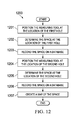
- a map of the spacing is created (operation 1207), with the process terminating thereafter. It will be appreciated that a map of spacing may thus be created for a number of holes.
- each block in the flowcharts or block diagrams may represent a module, segment, an operation, or a portion of computer usable or readable program code, which comprises one or more executable instructions for implementing the specified function or functions.
- Some of the blocks may be performed by human operators, machines, or other types of operators.
- the function or functions noted in the block may occur out of the order noted in the figures.
- two blocks shown in succession may be executed substantially concurrently, or the blocks may sometimes be executed in the reverse order, depending upon the functionality involved.
- a measuring tool may be positioned so that an operator may take a measurement of the space between a first part and a second part wherein the space has a restricted or limited access.
- a measuring tool may include, for example, a tube, a nose, a flange, a rod, and/or a measuring device.
- the tube, nose, rod, and/or measuring device may be positioned in a housing.
- the tube includes a first end, and the first end of the tube is configured to transition between a compressed position and an expanded position.
- the tube may also include at least one cutaway portion proximate to the first end. The cutaway portion may comprise a number of slots formed lengthwise along the tube.
- the flange may be disposed proximate the first end.
- the flange may have an upper surface and a lower surface, and the flange may be characterized by a thickness.
- the flange and the first end may be configured to pass through a hole of a first part when the first end is in the compressed position. Further, the flange may be configured such that the upper surface of the flange contacts a lower surface of the first part when the first end is in the expanded position.
- the rod may be disposed so as to move in the tube.
- the tube In order to receive the rod, the tube may be hollow and characterized by a channel.
- the rod may be configured to transition the tube to the expanded position when the rod is inserted in the tube proximate to the first end.
- the measuring device may be configured to record movement of the tube.
- an operator may quickly and efficiently take precision measurements of a space between structures.
- the embodiments described herein allow an operator to position a measuring tool in a space where conventional measuring devices could not make access.
- the slim configuration of the measuring tool and the linear movement of the tube of the measuring tool allow the tube to enter into and out of small apertures, such as fastener holes.
- the measuring tool can be positioned where conventional measuring systems could not be placed.
- the flange of the measuring tool may further be transitioned from a compressed position to an expanded position so as to allow the flange and tube to be positioned for taking measurements.
- the automated movement of the measuring tool such as by air actuation, allows quick and rapid measurements.
Landscapes
- Physics & Mathematics (AREA)
- General Physics & Mathematics (AREA)
- A Measuring Device Byusing Mechanical Method (AREA)
Abstract
Description
- The present disclosure to methods and apparatuses for measuring a space between components. Still more particularly, the present disclosure relates to the measurement of the space between components, such as aircraft components, where the space is accessible by a hole in one of the components.
- Manufacturing structures, such as those for aircraft, involve the assembly of different parts to form the structures. A certain level of fit between parts is desired but not always possible. For example, during manufacture of an aircraft tail assembly, the skin of a horizontal stabilizer is attached to a spar of the aircraft frame. The skin and spar are examples of adjacent pieces that may have a space between them.
- A shim may be placed in the space between adjacent parts. In certain cases, identifying the size of a space between the two adjacent parts with a desired level of precision may be needed to design a shim that provides as tight a fit in the space as desired.
- The physical configuration of assembled parts can present difficulties for measuring the space between the parts. For example, an operator may have difficulties in accessing the space between the parts to make measurements of the space. In some cases, a partial disassembly of parts may be performed to access the space. In other cases, access may be limited to an opening that may be present in the parts or between the parts. With these situations, measurements may not be made with as great a level of precision as desired. As a result, if a shim made for the space does not fit as tightly as desired, the shim may be reworked or replaced until a desired fit is obtained.
- As a result, the manufacturing of the aircraft may take more time and expense than desired to obtain a desired fit between parts. Accordingly, it would be advantageous to have a method and apparatus which takes into account one or more of the issues discussed above, as well as possibly other issues.
- The present disclosure provides a method and apparatus for measuring a space between parts. In one advantageous embodiment of the present disclosure, an apparatus is provided for measuring. The apparatus comprises an elongate member. An end of the elongate member is configured to move through a hole in a first structure into a space located between the first structure and a second structure. A flange extends from the elongate member, and the elongate member is configured to expand after the flange exits the hole in the first structure such that the flange is unable to pass back through the hole. A measurement system is configured to measure movement of the end elongate member in order to identify a length of the space between the first structure and the second structure.
- In another advantageous embodiment, an apparatus for measuring a space includes a tube, a flange, a rod, and a measuring device. The tube includes a first end. The first end of the tube is configured to transition between a compressed position and an expanded position. The tube may also include at least one cutaway portion proximate to the first end. The flange and the first end may be configured to pass through a hole of a first part when the first end is in the compressed position. Further, the flange may be configured such that the upper surface of the flange contacts a lower surface of the first part when the first end is in the expanded position. The rod may be disposed so as to move in the tube. The rod may be configured to transition the tube to the expanded position when the rod is inserted in the tube proximate to the first end. The measuring device may be configured to record movement of the tube.
- In still a further advantageous embodiment, a method is provided for measuring a space between a first part and a second part. The method includes steps of inserting a first end of a tube into a hole of the first part until a lower surface of a flange disposed on the tube contacts a first surface of the second part; making a measurement of distance between a first surface of the first part and the first surface of the second part as a first measurement; raising the tube until an upper surface of the flange disposed on the tube contacts a second surface of the first part; making a measurement of distance between the first surface of the first part and the second surface of the first part as a second measurement; and determining the space between the second surface of the first part and the first surface of the second part.
- In yet another advantageous embodiment, a method is provided for measuring a space between a first part and a second part. A first end of a tube is inserted into a hole of the first part until the first end of the tube contacts a first surface of the second part. A measuring device is zeroed when the first end of the tube contacts the first surface of the second part. An upper surface of a flange disposed on the first end of the tube is placed against a second surface of the first part. A measurement is made of the distance between the first surface and the second surface of the first part.
- The features, functions, and advantages can be achieved independently in various embodiments of the present disclosure or may be combined in yet other embodiments in which further details can be seen with reference to the following description and drawings.
-
-
FIG. 1 is an illustration of a diagram illustrating an aircraft manufacturing and service method; -
FIG. 2 is an illustration of a diagram of an aircraft in accordance with an advantageous embodiment; -
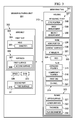
FIG. 3 is an illustration of a block diagram of a measurement environment in accordance with an advantageous embodiment; -
FIG. 4 is an illustration of a diagram of a tail assembly in accordance with an advantageous embodiment; -
FIG. 5 is an illustration of a cross-sectional diagram of a measuring tool in accordance with an advantageous embodiment; -
FIG. 6 is an illustration of a cross- sectional diagram of a measuring tool in accordance with an advantageous embodiment; -
FIG. 7 is another illustration of a cross-sectional diagram of a measuring tool in accordance with an advantageous embodiment; -
FIG. 8 is another illustration of a cross- sectional diagram of a measuring tool in accordance with an advantageous embodiment; -
FIG. 9 is an illustration of a flowchart of a process for measuring a space between a first part and a second part in accordance with an advantageous embodiment; -
FIG. 10 is an illustration of a flowchart of a process for zeroing a measuring device in accordance with an advantageous embodiment; -
FIG. 11 is an illustration of a flowchart of a process for measuring a space between a first part and a second part in accordance with an advantageous embodiment; and -
FIG. 12 is an illustration of a flowchart of a process for creating a map of spacing in accordance with an advantageous embodiment. - Referring more particularly to the drawings, embodiments of the disclosure may be described in the context of aircraft manufacturing and
service method 100 as shown inFIG. 1 andaircraft 200 as shown inFIG. 2 . Turning first toFIG. 1 , an illustration of an aircraft manufacturing and service method is depicted in accordance with an advantageous embodiment. During pre-production, aircraft manufacturing andservice method 100 may include specification anddesign 102 ofaircraft 200 inFIG. 2 andmaterial procurement 104. - During production, component and
subassembly manufacturing 106 andsystem integration 108 ofaircraft 200 inFIG. 2 takes place. Thereafter,aircraft 200 inFIG. 2 may go through certification anddelivery 110 in order to be placed inservice 112. While inservice 112 by a customer,aircraft 200 inFIG. 2 is scheduled for routine maintenance andservice 114, which may include modification, reconfiguration, refurbishment, and other maintenance or service. - Each of the processes of aircraft manufacturing and
service method 100 may be performed or carried out by a system integrator, a third party, and/or an operator. In these examples, the operator may be a customer. For the purposes of this description, a system integrator may include, without limitation, any number of aircraft manufacturers and major-system subcontractors; a third party may include, without limitation, any number of vendors, subcontractors, and suppliers; and an operator may be an airline, a leasing company, a military entity, a service organization, and so on. - With reference now to
FIG. 2 , an illustration of an aircraft is depicted in which an advantageous embodiment may be implemented. In this example,aircraft 200 is produced by aircraft manufacturing andservice method 100 inFIG. 1 and may includeairframe 202 with plurality ofsystems 204 and interior 206. Examples ofsystems 204 include one or more ofpropulsion system 208,electrical system 210,hydraulic system 212, andenvironmental system 214. Any number of other systems may be included. Although an aerospace example is shown, different advantageous embodiments may be applied to other industries, such as the automotive industry. - Apparatuses and methods embodied herein may be employed during at least one of the stages of aircraft manufacturing and
service method 100 inFIG. 1 . As used herein, the phrase "at least one of", when used with a list of items, means that different combinations of one or more of the listed items may be used and only one of each item in the list may be needed. For example, "at least one of item A, item B, and item C" may include, for example, without limitation, item A or item A and item B. This example also may include item A, item B, and item C or item B and item C. - In one illustrative example, components or subassemblies produced in component and
subassembly manufacturing 106 inFIG. 1 may be fabricated or manufactured in a manner similar to components or subassemblies produced whileaircraft 200 is inservice 112 inFIG. 1 . As yet another example, a number of apparatus embodiments, method embodiments, or a combination thereof may be utilized during production stages, such as component andsubassembly manufacturing 106 andsystem integration 108 inFIG. 1 . A number, when referring to items, means one or more items. For example, a number of apparatus embodiments are one or more apparatus embodiments. A number of apparatus embodiments, method embodiments, or a combination thereof may be utilized whileaircraft 200 is inservice 112 and/or during maintenance andservice 114 inFIG. 1 . The use of a number of the different advantageous embodiments may substantially expedite the assembly of and/or reduce the cost ofaircraft 200. - For example, one or more of the different advantageous embodiments may be used to make measurements of spaces between parts during, for example, without limitation, component and
subassembly manufacturing 106 andsystem integration 108. - The different advantageous embodiments recognize and take into account a number of different considerations. For example, the different advantageous embodiments recognize and take into account that access to the space between two parts may be made through holes in the parts. For example, the space between parts may be accessible through a hole in one of the parts. The size of the hole may not allow an operator making measurements to insert a tool in the hole to make a measurement of the space between the pieces.
- The different advantageous embodiments recognize and take into account that a manual feeler gauge is inadequate for measurements in these situations. This type of gauge has a configuration and/or size that prevents placing the gauge through the hole to make measurements of the space. The different advantageous embodiments recognize and take into account that enlarging holes or drilling new holes with a sufficient size for the gauge may be undesirable.
- The different advantageous embodiments recognize and take into account that having a tool and a method of using the tool that could make space measurements in structures that have restricted access is desirable. The different advantageous embodiments recognize and take into account that having a tool and a method of using the tool that allows the operator to make measurements with a desired level of precision is desirable. The different advantageous embodiments recognize and take into account that having a method and apparatus that allows an operator to take multiple measurements of multiple locations more quickly and precisely as compared to current systems is desirable.
- The different advantageous embodiments recognize and take into account that measurement of spaces between parts is difficult or impossible using known methods, particularly in structures offering restricted access. There may be insufficient room through which to position a measuring device, such as a feeler gauge. Additionally, the different advantageous embodiments recognize and take into account that cutting access passages or manholes in certain structures, such as aircraft assemblies, to allow physical access is undesirable. The different advantageous embodiments also recognize and take into account that measurement of multiple spaces at multiple locations using known methods is a cumbersome and time-consuming process.
- Thus, the different advantageous embodiments provide a method and apparatus for measuring spaces between parts. An apparatus comprises an elongate member, a flange extending from the elongate member, and a measurement system. An end of the elongate member is configured to move through a hole in a first structure into a space located between the first structure and a second structure. The elongate member is configured to expand after the flange exits the hole in the space such that the flange is unable to pass back through the hole. The measurement system is configured to measure movement of the end elongate member to identify a length of the space between the first structure and the second structure.
- With reference now to
FIG. 3 , an illustration of a block diagram illustrating a measuring environment is depicted in accordance with an advantageous embodiment. In this example,measurement environment 301 includes measuringtool 313 that may be used in conjunction withassembly 302. In an advantageous embodiment illustrated inFIG. 3 , measuringtool 313 is implemented to measurespace 309 existing betweenfirst part 303 andsecond part 311 inassembly 302. - Measuring
tool 313 includestube 314.Tube 314 may comprise a general elongate member. In an advantageous embodiment,tube 314 may be a hollow tube that includesfirst end 317.First end 317 oftube 314 may transition back and forth between expandedposition 315 andcompressed position 316.Flange 320 may be disposed proximate tofirst end 317 oftube 314.Flange 320 may includeupper surface 321 andlower surface 322. Additionally,flange 320 may be characterized bythickness 323 andflange diameter 335. - Measuring
tool 313 may also compriserod 324.Tube 314, when defining a hollow tube, may definechannel 331.Rod 324 may be disposed withinchannel 331 oftube 314 such thatrod 324 may move withintube 314 with a generally linear movement. In other words,rod 324 may move along an axis extending centrally thoughtube 314.Rod 324 may thus move such that at least a portion ofrod 324 is proximate tofirst end 317 oftube 314. In an advantageous embodiment,tube 314 may be configured to takecompressed position 316 whenrod 324 is not positioned withintube 314. Disposingrod 324 withintube 314 such that a portion ofrod 324 is disposed proximate tofirst end 317 oftube 314 and may transitiontube 314 to expandedposition 315. Removingrod 324 fromtube 314 allowstube 314 to return tocompressed position 316. - In an advantageous embodiment,
tube 314 is substantially circular in an outer shape. However,tube 314 may take other outer shapes, both curved and angled, such as, for example, hexagonal or octagonal. In oneadvantageous embodiment rod 324 may be substantially cylindrical in shape, althoughrod 324 may take other shapes.Channel 331 may be configured with a shape so as to receiverod 324 and to allowrod 324 to move withinchannel 331.Rod 324 may move in a substantially linear direction withintube 314.Channel 331 may extend fromfirst end 317 oftube 314 to a further opening (not shown) which allowsrod 324 to entertube 314. - In an advantageous embodiment, measuring
tool 313 may also includenose 325.Nose 325 may be disposed to generally surroundfirst end 317 oftube 314.First end 317 oftube 314 may move in and out ofnose 325. Inhome position 326,first end 317 oftube 314 is positioned withinnose 325. Further, inhome position 326,lower surface 322 offlange 320 is substantially parallel withcontact surface 336 ofnose 325.First end 317 oftube 314 may move out ofnose 325 and away fromhome position 326. One ormore stabilizers 351 may be positioned proximate tonose 325.Stabilizers 351 may be used in positioning of measuringtool 313. -
Nose 325 may provide a function of protectingtube 314,first end 317, andflange 320. Additionally,nose 325 may provide a function of squaring or aligningmeasuring tool 313 with respect tofirst part 303 in order to perform measurements as described herein. Further,nose 325 may provide the function of contactingfirst part 303 so as to provide a start position for a series of measurements and movements of measuringtool 313. - Measuring
tool 313 may also include measuringdevice 327. Measuringdevice 327 may comprise any appropriate measuring apparatus for taking measurements as further described herein. For example, measuringdevice 327 may comprise a measuring device that measures linear movement oftube 314. Measuringdevice 327 may comprise, by way of example only, a laser tool, a micrometer, or a dial gauge. Measuringdevice 327 may be configured to be zeroed and to take multiple measurements during usage of measuringtool 313. For example, whenfirst end 317 oftube 314 is inhome position 326, measuringdevice 327 may be in zeroposition 328.First measurement 329 andsecond measurement 330 may be taken when measuringtool 313 is put in a different configuration as discussed further herein. - In an advantageous embodiment, measuring
tool 313 also includeshousing 341, which may generally surround and protect components of measuringtool 313, includingtube 314,flange 320,rod 324, and measuringdevice 327. - In one advantageous embodiment, measuring
tool 313 may take the general form of a hand tool. For example, a hand tool may be a tool generally used manually by a worker. In another advantageous embodiment, measuringtool 313 may take the form of an automated tool, such as a tool connected to a robotic arm. - Measuring
tool 313 may be any appropriate tool for performing a desired measuring operation onassembly 302. In one advantageous embodiment,assembly 302 may be an assembly of parts or structures, such as, for example, an assembly of an aircraft. In one advantageous embodiment, measuringtool 313 is used to measurespace 309 that exists betweenfirst part 303 andsecond part 311 ofassembly 302. -
Assembly 302 may includefirst part 303 andsecond part 311.First part 303 hassurfaces 306 that includefirst surface 307 andsecond surface 308.Second part 311 hasfirst surface 312.Space 309 is located betweenfirst surface 307 offirst part 303 andfirst surface 312 ofsecond part 311.First part 303 may also havehole 304.Hole 304 hasdiameter 305.Shim 310 is shown with shadow lines inFIG. 3 .Shim 310 represents that it may be desired to fitshim 310 intospace 309 that exists betweenfirst part 303 andsecond part 311. - The illustration of measuring
environment 301 inFIG. 3 is not meant to imply physical or architectural limitations to the manner in which an advantageous embodiment may be implemented. Other components in addition to and/or in place of the ones illustrated may be used. Some components may be unnecessary. Also, the blocks are presented to illustrate some functional components. One or more of these blocks may be combined and/or divided into different blocks when implemented in an advantageous embodiment. - In an advantageous embodiment, measuring
tool 313 includes a substantiallyrectangular housing 341 that encloses other features of measuringtool 313.Housing 341 may enclose measuringdevice 327,nose 325, andflange 320. In another advantageous embodiment,assembly 302 comprises a first structure, which corresponds tofirst part 303, and a second structure, which corresponds tosecond part 311. An aircraft skin may be an example offirst part 303 or first structure, and an aircraft spar may be an example ofsecond part 311 or a second structure. - With reference now to
FIG. 4 , an illustration of a diagram of ameasuring tool 406 is depicted in accordance with an advantageous embodiment. In this example, measuringtool 406 is an example of a physical implementation of measuringtool 313 shown in block form inFIG. 3 . - In this illustrative example, measuring
tool 406 is used in conjunction withtail assembly 402 ofaircraft 401.Aircraft 401 is an example of one physical implementation ofaircraft 200 inFIG. 2 .Tail assembly 402 includeshorizontal stabilizer 403.Horizontal stabilizer 403 includesskin 404 and spars 405.Spars 405 are shown in dashed lines to illustrate that spars 405 may be positioned belowskin 404.Skin 404 and spars 405, in this example, illustrate one example offirst part 303 andsecond part 311 inFIG. 3 . - A manufacturing process may be used to affix
skin 404 to spars 405. Measuringtool 406 may be used to make measurements. In this example, measuringtool 406 is disposed onskin 404 ofhorizontal stabilizer 403. Measuringtool 406 may be positioned such that a tube (not shown) passes through holes so as to measure the space betweenskin 404 and spars 405. InFIG. 4 , lines 5-5 illustrate a cross-sectional take off as shown inFIG. 5 below. -
FIG. 4 also illustrates some of the features of measuringtool 406 as shown in this example. Measuringtool 406 may includehousing 431, which is generally configured to protect measuringtool 406.Housing 431 generally surrounds components of measuringtool 406. -
Switch 432 may be positioned onhousing 431.Switch 432 may be used in taking measuring operations as described herein, such as zeroing, taking a first measurement, and taking a second measurement. - Additionally, measuring
tool 406 may include plug 433. Plug 433 may provide a connectivity to measuringtool 406 for other auxiliary applications, which are not illustrated. Plug 433 may thus receive electrical power, data or digital connectivity, and mechanical power lines. Mechanical power to measuringtool 406 may take various embodiments, such as, but not limited to, air pressure, hydraulic power, and electrical power. - Turning now to
FIG. 5 , an illustration of a diagram of a measuring tool as illustrated inFIG. 4 is depicted.FIG. 5 is an illustration of a cross-sectional diagram following the cross-sectional lines 5-5 ofFIG. 4 . In this view, measuringtool 406 includesnose 502,tube 503, andflange 512. Also, as shown inFIG. 4 , measuringtool 406 includeshousing 431,switch 432, and plug 433. Also shown inFIG. 5 arestabilizers 561, which may be used to furtherposition measuring tool 406 onaircraft skin 404. Withinhousing 431 of measuringtool 406 aresensor 563 andair actuator 565.Sensor 563 comprises a measuring device as described herein.Air actuator 565 comprises an advantageous embodiment of howtube 503 may be moved through use of air pressure. - As depicted in
FIG. 5 ,flange 512 is connected tofirst end 511 oftube 503.First end 511 oftube 503 is in a compressed position. In the compressed position, the diameter offlange 512 allowsflange 512 to pass throughhole 510 ofaircraft skin 404. Preferably, in the compressed position, the diameter offlange 512 is less than or approximately equal to the diameter ofhole 510.Aircraft skin 404 is positioned relative tospars 405 so as to definespace 509 therebetween.Flange 512 has moved belowfirst surface 506 offirst part 504; however,flange 512 is abovesecond surface 507 offirst part 504.Flange 512 still remains abovefirst surface 508 ofsecond part 505. - Referring still to
FIG. 5 , the physical dimensions of measuringtool 406 may vary. In an advantageous embodiment,housing 431 comprises a substantially rectangular or boxlike shape. The dimensions of the base and top ofhousing 431 are substantially equivalent and substantially square. A typical width, w, is givenreference number 555, and width, w, may vary between about 1.5 to about 3.0 inches. The length ofhousing 431, noted byreference 557 may vary between about six to about eight inches. - With respect to the measurements obtained by measuring
tool 406, the precision of measurements may also vary. In the advantageous embodiment, where measuringtool 406 is used to measure a space betweenskin 404 and spar 405, measurements may be taken with a variation of less than about 0.005 inch. In the advantageous embodiment, a measuring sensor manufactured by Sony Corporation is used. The measuring sensor is a Magnescale® Series Linear Encoder denoted by part number SR118. The sensor makes measurements of linear movement using electric and/or magnetic detection. - A typical hole, such as
hole 510 inFIG. 5 , also has a dimension that may vary. For example,hole 510, which may be substantially cylindrical in cross section, may have a diameter and a length that may vary.Hole 510 is also depicted as having a generally vertical arrangement with respect to the orientation ofFIG. 5 ; however,hole 510 may be oriented at a slant. In other words, a central axis (not shown) ofhole 510 may be set at some angle other than 90 degrees relative tofirst surface 506 ofaircraft skin 404.Hole 510 may be a hole that has been drilled to receive a fastener or other structure therethrough. In an advantageous embodiment,hole 510 is characterized byhole diameter 305 inFIG. 3 of between about 0.125 to about 0.5 inches.Tube 503 may include a diameter that allowstube 503 to pass throughhole 510, and thus the diameter oftube 503 may vary as described with respect tohole 510.Nose 502 may take various outer shapes. In an advantageous embodiment,nose 502 is substantially cylindrical.Nose 502 may includediameter 559, shown by "d", that preventsnose 502 from passing intohole 510. In an advantageous embodiment,nose 502 includesdiameter 559 of between about one to about three inches. - Turning now to
FIGS. 6 ,7 , and8 , several illustrations of diagrams showing portions of measuringtool 406 are depicted in accordance with an advantageous embodiment.FIGS. 6 ,7 , and8 illustrate portions of measuringtool 406 in different positions used to measurespace 606. - With reference first to
FIG. 6 , some structures of measuringtool 406, such ashousing 431,nose 502,sensor 563, andair actuator 565 are not shown to better illustrate the manner in which measurements are made. Only portions, or some portions, of measuringtool 406 are depicted to illustrate the manner in which measurements are made.FIGS. 6 ,7 , and8 also depict structures, such asfirst part 604,second part 605, andspace 606, which may correspond toaircraft skin 404 and spars 405. - As depicted,
tube 601 in measuringtool 406 has been extended so as to pass throughhole 630 and intospace 606.First end 602 oftube 601 has passed throughfirst surface 607 offirst part 604.Rod 611 has been inserted intochannel 612 oftube 601.Rod 611 has been inserted such that a portion ofrod 611 is disposed proximate tofirst end 602 oftube 601. This positioning ofrod 611 causesfirst end 602 oftube 601 to transition from the compressed position to the expanded position. -
Slots 610 have allowedfirst end 602 to move to the expanded position. In the expanded position, the diameter offlange 603 is now greater than the diameter ofhole 630. In the expanded position,flange 603 cannot pass throughhole 630. InFIG. 6 , it is also noted thatflange 603 has not yet contacted any surfaces offirst part 604 orsecond part 605. As depicted inFIG. 6 ,first end 602 oftube 601 is positioned betweenfirst part 604 andsecond part 605.Space 606 is betweensecond surface 608 offirst part 604 andfirst surface 609 ofsecond part 605. In the position shown inFIG. 6 ,upper surface 621 andlower surface 622 offlange 603 are not in contact withfirst part 604 orsecond part 605. - Turning now to
FIG. 7 , an illustration of a diagram showing a measuring tool in another position is depicted in accordance with an advantageous embodiment. In this illustrative example,tube 601 of measuringtool 406 has been further extended relative toFIG. 6 .Tube 601 has moved further belowfirst surface 607 offirst part 604 andsecond surface 608 offirst part 604. Movement oftube 601 includes movement throughhole 630. Rod 611 (not shown) remains inchannel 612.Flange 603 offirst end 602 has now contactedsecond part 605. More particularly,lower surface 622 offlange 603 is in contact withfirst surface 609 ofsecond part 605.Upper surface 621 offlange 603 is not in contact with a surface. In moving to the position inFIG. 7 ,tube 601 has not transitioned out of the expanded position, and thus,slots 610 do not move relative to their position inFIG. 6 . At this point, a first measurement is taken, such asfirst measurement 329 ofFIG. 3 . - Turning now to
FIG. 8 , an illustration of a diagram of a measuring tool in another position is depicted in accordance with an advantageous embodiment. As depicted, measuringtool 406 has been repositioned relative toFIG. 7 .Tube 601 has been moved away fromsecond part 605 and is now in contact withfirst part 604. More particularly,upper surface 621 offlange 603 is in contact withsecond surface 608 offirst part 604.Lower surface 622 offlange 603 is not in contact with any surface.Flange 603 is abovefirst surface 609 ofsecond part 605. In moving to the position inFIG. 8 fromFIG. 7 ,flange 603 has further moved throughspace 606 in a direction towardfirst part 604. Movement oftube 601 includes a movement throughhole 630. In this position, a measurement may be taken, such assecond measurement 330 ofFIG. 3 . It is noted inFIG. 8 thatflange 603 makes contact withfirst part 604, becauseflange 603, being in the expanded position, is not free to pass throughhole 630. Thus, astube 601 was drawn up from its position inFIG. 7 to its position inFIG. 8 ,flange 603 makes contact withfirst part 604 and restricts further movement oftube 601 in the upwardly vertical direction (relative to the orientation ofFIG. 8 ). - When
tube 601 is to be extracted from the positionFIG. 8 ,tube 601 can be transitioned to the compressed position. This may be achieved by withdrawingrod 611 fromtube 601. Withdrawingrod 611 allowstube 601 to convert or transition to its natural or rest state, the compressed position.Slots 610 cooperate in allowing the transition. In the compressed position, the diameter offlange 603 is such that it allowsflange 603 andtube 601 to be moved pastfirst part 604. - In the above description of
FIGS. 5-8 , the first end oftube 601 has been described as being in the compressed position when at rest or in its natural condition.Tube 601 is transitioned to the expanded position by insertion ofrod 611 intotube 601, and thentube 601 transitions to the compressed position whenrod 611 is removed fromtube 601. It is noted that other configurations are possible. For example,tube 601 may be configured so as to be in an expanded position when at rest. In this example,tube 601 may be converted to the compressed position by placing a compressor (not shown), such as a sliding sleeve, over an external position offirst end 602 oftube 601. The compressor may be configured with a diameter such that the compressor squeezesfirst end 602 oftube 601, thereby allowingfirst end 602 to move. - Referring still to
FIG. 8 , measurements taken in accordance with an advantageous embodiment are shown asfirst measurement 805 andsecond measurement 807.First measurement 805, taken whenflange 603 is in the position shown inFIG. 7 , represents the distance betweenfirst surface 607 offirst part 604 andfirst surface 609 ofsecond part 605.First measurement 805 may be taken bysensor 563 ofFIG. 5 as a measurement of linear travel oftube 601 fromfirst surface 607 tofirst surface 609.Second measurement 807, taken whenflange 603 is in the position shown inFIG. 8 , represents the distance betweenfirst surface 609 ofsecond part 605 andsecond surface 608 offirst part 604.Second measurement 807 may be taken bysensor 563 ofFIG. 5 as a measurement of linear travel oftube 601 fromfirst surface 609 tosecond surface 608. The precision offirst measurement 805 andsecond measurement 807 may be enhanced by zeroingtube 601 whenflange 603 is inhome position 326 as inFIG. 3 andnose 325 is in zeroposition 328 as inFIG. 3 . The step of zeroingmeasuring tool 406 is further described herein with respect to a measuring method described inFIG. 10 below. -
Space 809, which represents the distance betweenfirst surface 609 andsecond surface 608, may be determined by subtractingsecond measurement 807 fromfirst measurement 805 while also allowing forthickness 323 as inFIG. 3 offlange 603. Determiningspace 809 may take intoaccount thickness 323, becausesecond measurement 807 is affected by the travel oftube 601 as limited byflange 603. InFIG. 8 ,upper surface 621 offlange 603 contactssecond surface 608, whereas inFIG. 7 ,lower surface 622 offlange 603 contactsfirst surface 609.Thickness 323 as inFIG. 3 offlange 603 may be a known quantity. - The illustrations in
FIGS. 5-8 are illustrations of an advantageous embodiment and are not meant to limit the manner in which the measuring tool can be implemented or the manner in which measurements can be taken. The order of movement in measuringtool 406, as shown inFIGS. 6 ,7 , and8 , is an illustration of one advantageous embodiment. The measurements ofFIG. 8 are efficiently taken as they track the movement of measuringtool 406, and are, therefore examples of how measurements may be efficiently taken. - For example, when measuring multiple holes in an aircraft horizontal stabilizer, the measuring tool will transition from hole to hole and will move into and out of the different holes. However, in another example, a measurement may also be taken in which the measurement comprises the movement of
tube 601 fromfirst surface 609 ofsecond part 605 tosecond surface 608 offirst part 604. In another embodiment, a measurement may be taken of the travel oftube 601 fromsecond surface 608 offirst part 604 tofirst surface 609 ofsecond part 605. Other kinds of measurements may also be taken. - In the description of an advantageous embodiment of
FIGS. 6 ,7 , and8 , it is also noted that the transitioning movement offirst end 602 oftube 601 is facilitated by the positioning ofslots 610 infirst end 602 oftube 601.Tube 601 may be formed with a plurality ofslots 610. In an advantageous embodiment,slots 610 comprise cutaway portions oftube 601 that extend in a generally vertical direction. The number, size, and positioning ofslots 610 may be selected so as to allow for easy transitioning movement offirst end 602 oftube 601 from the compressed position to the expanded position and back to the compressed position. -
Tube 601 and measuringtool 406 may generally be constructed of any materials that allow the functions described herein. Generally, metals and metallic alloys provide acceptable materials for the structure of measuringtool 406 as described. Aluminum alloys are an example of a material from which measuringtool 406 andtube 601 may be constructed. Other examples of metals that may be used include steel alloys, nickel-steel alloys, titanium, and titanium alloys. Other materials, such as plastics, ceramics, and composites, may also be used. - With reference now to
FIG. 9 , an illustration of a flowchart of a process for measuring is depicted in accordance with an advantageous embodiment. The process is generally designated byreference number 900 and may be a process for measuring a space between a first part and a second part. One example of the process may be measuring the space between a skin and a spar in a horizontal stabilizer of a tail assembly as depicted inFIG. 4 . The method may be implemented, for example, using measuringtool 313 interacting withassembly 302 ofFIG. 3 , and the following reference numbers will track the structures and features of those figures. -
Process 900 may begin by transitioningfirst end 317 oftube 314 into compressed position 316 (operation 901). In an advantageous embodiment,first end 317 oftube 314 may naturally be incompressed position 316. In other embodiments, steps may need to be taken to transitionfirst end 317 tocompressed position 316. In one example, a compressor or sleeve slides proximate tofirst end 317 in order to transitionfirst end 317 tocompressed position 316. - In a further step,
first end 317 oftube 314 is inserted intohole 304 offirst part 303 of assembly 302 (operation 902).Flange 320 connected tofirst end 317 oftube 314 is sized incompressed position 316 so as to pass throughhole 304. In an advantageous embodiment,hole 304 is a fastener hole that either exists or is formed in the first part. As one example,first part 303 may comprise an aircraft skin, andhole 304 comprises a fastener hole formed in the skin. - In a further step,
tube 314 is lowered or moved throughhole 304 offirst part 303 until a lower surface offlange 320 contacts first surface 312 of second part 311 (operation 903). In an advantageous embodiment,second part 311 may comprisespars 405 to whichaircraft skin 404 is to be attached.First measurement 329 may now be taken (operation 904). - In a further step,
first end 317 oftube 314 is transitioned to expandedposition 315 from compressed position 316 (operation 905). The transition fromcompressed position 316 to expandedposition 315 may occur by insertingrod 324 intochannel 331 oftube 314. Movement ofrod 324 to a position proximate tofirst end 317 oftube 314 transitionsfirst end 317 oftube 314 to expandedposition 315. - In a further step,
first end 317 oftube 314 is raised or moved untilupper surface 321 offlange 320 contactssecond surface 308 of first part 303 (operation 906). In expandedposition 315,flange 320 hasflange diameter 335 that is greater thanhole 304, soflange 320 is prevented from passing throughhole 304.Second measurement 330 may now be taken (operation 907). - In a further step,
space 309 betweenfirst part 303 andsecond part 311 is determined (operation 908).Space 309 comprises the distance betweenfirst surface 312 ofsecond part 311 andsecond surface 308 offirst part 303. In an advantageous embodiment, the determination ofspace 309 is the difference ofsecond measurement 330 fromfirst measurement 329 with an allowance forthickness 323 offlange 320. - Measurements, such as in first measurement (operation 904) and second measurement (operation 907), may be taken using known measuring devices. Known measuring devices include laser devices, linear movement devices, dial gauges, and micrometers. A measurement may include, for example, both a notation of position, as well as a measure of movement of the tube.
- In a further step,
first end 317 oftube 314 is transitioned to compressed position 316 (operation 909). In an advantageous embodiment,operation 909 may be achieved by removingrod 324 fromchannel 331 oftube 314. This allowsfirst end 317 oftube 314 to return to its relaxed or natural condition, which is compressedposition 316. Incompressed position 316,flange 320 will haveflange diameter 335 less thandiameter 305 ofhole 304, andtube 314 can be withdrawn throughhole 304. - In a further step, the above series of operations may be repeated for other hole locations (operation 910). In the advantageous embodiment where measurements are taken of the space between
skin 404 and spars 405, the series of operations may be repeated for multiple holes inskin 404. - In this manner, a mapping of the space between the skin and an underlying spar or series of spars may be taken. The mapping will represent the spacing measured at each of the multiple hole locations. The spacing information may also be transferred to a controller, memory, or other computer-assisted device so as to record and process the spacing information as further described herein with respect to FIG. 13. The spacing information may then be used to design and
fashion shim 310 that would fit withinspace 309. - Referring now to
FIG. 10 , an illustration of a flowchart of a process for zeroing a measuring device is depicted. The method ofFIG. 10 may again be performed with measuringtool 313 andassembly 302 ofFIG. 3 and is described with respect to features therein. The process is generally indicated byreference number 1000. The steps inFIG. 10 may be performed in conjunction with the steps shown inFIG. 9 . In one operation,first end 317 oftube 314 is placed inhome position 326 in nose 325 (operation 1001). - Next,
nose 325 is lowered untilcontact surface 336 ofnose 325 contacts first surface 307 of first part 303 (operation 1002). Afterwards, measuringdevice 327 is zeroed to zero position 328 (operation 1003), with the process terminating thereafter. In an advantageous embodiment of the steps ofFIG. 10 ,nose 325 of measuringtool 313 is placed in contact with the upper surface of an aircraft skin. Here,lower surface 322 offlange 320 is substantially aligned withcontact surface 336 ofnose 325 inhome position 326. The measuring device is zeroed at that position. - With reference now to
FIG. 11 , an illustration of a flowchart of a process for measuring the space between parts is depicted. The process is generally indicated byreference number 1100. Again, the steps are described with respect to elements inFIG. 3 . First,tube 314 is lowered throughhole 304 untillower surface 322 offlange 320 contacts first surface 312 of second part 311 (operation 1101). At this position, measuringdevice 327 is zeroed (operation 1102). Next,tube 314 is raised untilupper surface 321 offlange 320 contactssecond surface 308 of first part 303 (operation 1103). The measurement is taken whentube 314 is at the position ofstep 1103 withupper surface 321 offlange 320 in contact withsecond surface 308 of first part 303 (operation 1104), with the process terminating thereafter. - With reference now to
FIG. 12 , an illustration of a flowchart of a process for creating a map of a space between parts is depicted. The flowchart is again described with reference to elements as described inFIG. 3 . The process is generally indicated byreference number 1200. In one step of the process, measuringtool 313 is positioned at the location of a first hole (operation 1201). A space at the first hole location is determined (operation 1202). The space represents the space betweenfirst part 303 andsecond part 311, such as the spacing between an aircraft skin and a spar in an aircraft assembly. The space is recorded on a database (operation 1203). In a further step, measuringtool 313 is positioned at a second hole location (operation 1204). The space is determined at the location of the second hole (operation 1205). The space may be recorded on a database (operation 1206). In a further step, a map of the spacing is created (operation 1207), with the process terminating thereafter. It will be appreciated that a map of spacing may thus be created for a number of holes. - The flowcharts and block diagrams in the different depicted embodiments illustrate the architecture, functionality, and operation of some possible implementations of apparatus, methods, and computer program products. In this regard, each block in the flowcharts or block diagrams may represent a module, segment, an operation, or a portion of computer usable or readable program code, which comprises one or more executable instructions for implementing the specified function or functions. Some of the blocks may be performed by human operators, machines, or other types of operators.
- In some alternative implementations, the function or functions noted in the block may occur out of the order noted in the figures. For example, in some cases, two blocks shown in succession may be executed substantially concurrently, or the blocks may sometimes be executed in the reverse order, depending upon the functionality involved.
- In an advantageous embodiment of the disclosure described herein, a measuring tool is provided that may be positioned so that an operator may take a measurement of the space between a first part and a second part wherein the space has a restricted or limited access. A measuring tool may include, for example, a tube, a nose, a flange, a rod, and/or a measuring device. The tube, nose, rod, and/or measuring device may be positioned in a housing. The tube includes a first end, and the first end of the tube is configured to transition between a compressed position and an expanded position. The tube may also include at least one cutaway portion proximate to the first end. The cutaway portion may comprise a number of slots formed lengthwise along the tube. The flange may be disposed proximate the first end. The flange may have an upper surface and a lower surface, and the flange may be characterized by a thickness. The flange and the first end may be configured to pass through a hole of a first part when the first end is in the compressed position. Further, the flange may be configured such that the upper surface of the flange contacts a lower surface of the first part when the first end is in the expanded position. The rod may be disposed so as to move in the tube. In order to receive the rod, the tube may be hollow and characterized by a channel. The rod may be configured to transition the tube to the expanded position when the rod is inserted in the tube proximate to the first end. The measuring device may be configured to record movement of the tube.
- In an advantageous embodiment of the disclosure described herein, an operator may quickly and efficiently take precision measurements of a space between structures. In the assembly of aircraft, the embodiments described herein allow an operator to position a measuring tool in a space where conventional measuring devices could not make access. The slim configuration of the measuring tool and the linear movement of the tube of the measuring tool allow the tube to enter into and out of small apertures, such as fastener holes. The measuring tool can be positioned where conventional measuring systems could not be placed. The flange of the measuring tool may further be transitioned from a compressed position to an expanded position so as to allow the flange and tube to be positioned for taking measurements. Further, the automated movement of the measuring tool, such as by air actuation, allows quick and rapid measurements.
- The description of the different advantageous embodiments has been presented for purposes of illustration and description and is not intended to be exhaustive or limited to the embodiments in the form disclosed. Many modifications and variations will be apparent to those of ordinary skill in the art. Further, different advantageous embodiments may provide different advantages as compared to other advantageous embodiments. The embodiment or embodiments selected are chosen and described in order to best explain the principles of the embodiments, the practical application, and to enable others of ordinary skill in the art to understand the disclosure for various embodiments with various modifications as are suited to the particular use contemplated.
Claims (15)
- An apparatus comprising:an elongate member, wherein an end of the elongate member is configured to move through a hole in a first structure into a space located between the first structure and a second structure;a flange extending from the elongate member wherein the elongate member is configured to expand after the flange exits the hole in the first structure such that the flange is unable to pass back through the hole; anda measurement system configured to measure movement of the end of the elongate member to identify a length of the space between the first structure and the second structure.
- The apparatus of claim 1 wherein the elongate member has a channel extending from a first end of the elongate member, and further comprising a rod configured to move inside the channel wherein the elongate member is configured to expand when the rod is moved from a first position to a second position after the flange exits the hole in the first structure.
- The apparatus of claim 2 wherein the elongate member has a substantially cylindrical shape, and further comprising a number of slots extending a distance from the end of the elongate member.
- The apparatus of any of claims 1-3 wherein the measurement system is configured to measure a first distance from an outer surface of the first structure to an inner surface of the second structure and a second distance from the outer surface of the first structure and the inner surface of the first structure wherein the distance of the space is a difference between the first distance and the second distance.
- An apparatus for measuring a space comprising:a tube having a first end wherein the first end of the tube is configured to transition between a compressed position and an expanded position, the tube having at least one cutaway portion proximate to the first end;a flange disposed proximate to the first end, the flange having an upper surface and a lower surface, and the flange characterized by a thickness; the flange and the first end are configured to pass through a hole of a first part when the first end is in the compressed position and the flange is configured such that the upper surface of the flange contacts a lower surface of the first part when the first end is in the expanded position;a rod moveably disposed in the tube wherein the rod is configured to transition the tube to the expanded position when the rod is inserted in the tube proximate to the first end; anda measuring device configured to record movement of the tube.
- The apparatus of claim 5 wherein the first end of the tube is in the compressed position when at rest.
- The apparatus of claim 6 wherein the first end of the tube is configured to move to the compressed position when the rod is removed from the tube.
- The apparatus of claim 5 wherein the first end of the tube is in the expanded position when at rest.
- The apparatus of claim 8 further comprising a compressor configured to move linearly along an outer surface of the tube such that moving the compressor proximate to the first end of the tube and over the cutaway portion transitions the first end of the tube into the compressed position.
- A method for measuring a space between a first part and a second part comprising the steps of:inserting a first end of a tube into a hole of the first part until a lower surface of a flange disposed on the tube contacts a first surface of the second part;making a measurement of distance between a first surface of the first part and the first surface of the second part as a first measurement;raising the tube until an upper surface of the flange disposed on the tube contacts a second surface of the first part;making the measurement of distance between the first surface of the first part and the second surface of the first part as a second measurement; anddetermining the space between the second surface of the first part and the first surface of the second part.
- The method of claim 10 further comprising the step of zeroing a measuring device when a nose disposed around the first end of the tube is placed in contact with the first surface of the first part.
- The method of either claim 10 or 11 further comprising the step of expanding the first end of the tube to an expanded position when the first end of the tube is positioned within the space between the first part and the second part.
- The method of claim 12 wherein the step of expanding the first end of the tube further comprises inserting a rod in the tube so as to expand the first end of the tube.
- The method of any of claims 10-13 wherein the step of determining the space comprises subtracting the second measurement from the first measurement and allowing for a thickness of the flange.
- The method of any of claims 10-14 wherein the step of making the measurement of distance between the first surface of the first part and the first surface of the second part as the first measurement and the step of making a measurement of distance between the first surface of the first part and the second surface of the first part as the second measurement are performed in reverse order.
Applications Claiming Priority (1)
| Application Number | Priority Date | Filing Date | Title |
|---|---|---|---|
| US13/169,945 US8336222B1 (en) | 2011-06-27 | 2011-06-27 | Method and apparatus for measuring spaces with limited access |
Publications (2)
| Publication Number | Publication Date |
|---|---|
| EP2541190A1 true EP2541190A1 (en) | 2013-01-02 |
| EP2541190B1 EP2541190B1 (en) | 2023-10-04 |
Family
ID=46639281
Family Applications (1)
| Application Number | Title | Priority Date | Filing Date |
|---|---|---|---|
| EP12171644.3A Active EP2541190B1 (en) | 2011-06-27 | 2012-06-12 | Method and apparatus for measuring spaces with limited access |
Country Status (4)
| Country | Link |
|---|---|
| US (1) | US8336222B1 (en) |
| EP (1) | EP2541190B1 (en) |
| JP (1) | JP6397605B2 (en) |
| CA (1) | CA2775866C (en) |
Cited By (2)
| Publication number | Priority date | Publication date | Assignee | Title |
|---|---|---|---|---|
| CN104482840A (en) * | 2014-11-20 | 2015-04-01 | 航天海鹰(镇江)特种材料有限公司 | Force application device and detection method for detecting mold attaching gap of composite material wall plate |
| EP3318372A3 (en) * | 2016-10-16 | 2019-03-13 | The Boeing Company | Method and apparatus for compliant robotic end-effector |
Families Citing this family (13)
| Publication number | Priority date | Publication date | Assignee | Title |
|---|---|---|---|---|
| JP6527813B2 (en) * | 2015-11-16 | 2019-06-05 | 株式会社Screenホールディングス | Coating apparatus, manufacturing apparatus and measuring method |
| US10168136B2 (en) | 2016-03-22 | 2019-01-01 | Rolls-Royce Corporation | Clearance gage |
| US10330453B2 (en) | 2017-03-29 | 2019-06-25 | Lockheed Martin Corporation | Wireless fastener grip gauge |
| CN109798828B (en) * | 2017-11-17 | 2022-11-22 | 上海仪器仪表研究所 | Flange positioning instrument |
| KR101949085B1 (en) | 2018-06-21 | 2019-02-15 | 신윤은 | Method of measuring the front inner diameter length of a sheet carrier |
| CN109059728B (en) * | 2018-08-02 | 2023-09-22 | 江苏理工学院 | A circumferential hole position and size error detection tool |
| CN109579675B (en) * | 2019-01-09 | 2023-09-08 | 山东太古飞机工程有限公司 | Auxiliary measurement tool for measuring concave-convex degree of aircraft skin |
| CN111238347B (en) * | 2020-03-16 | 2021-07-27 | 常州市鑫亿莱精密机械有限公司 | Workpiece surface pit inspection device |
| CN113074613A (en) * | 2020-03-16 | 2021-07-06 | 江山市发发科技有限公司 | Rod end face blind hole depth detection device |
| CN111238345B (en) * | 2020-03-16 | 2021-08-17 | 长沙五量汽车配件有限公司 | Depth detection method of blind hole on rod end face |
| CN111238346B (en) * | 2020-03-16 | 2022-02-25 | 江山跟政科技有限公司 | Workpiece surface pit inspection method |
| US12693110B2 (en) | 2021-04-07 | 2026-07-28 | The Boeing Company | Non-contact automated measurement for interface gaps |
| US11920915B2 (en) * | 2021-04-07 | 2024-03-05 | The Boeing Company | Non-contact measurement for interface gaps |
Citations (3)
| Publication number | Priority date | Publication date | Assignee | Title |
|---|---|---|---|---|
| US3706307A (en) * | 1970-07-08 | 1972-12-19 | Hollister Inc | Gynecological instrument |
| EP2008585A1 (en) * | 2007-06-28 | 2008-12-31 | Stryker Trauma GmbH | Measuring device for measuring a length of a through-hole in a bone |
| US20110125271A1 (en) * | 1999-08-18 | 2011-05-26 | Intrinsic Therapeutics, Inc. | Method of performing an anchor implantation procedure within a disc |
Family Cites Families (19)
| Publication number | Priority date | Publication date | Assignee | Title |
|---|---|---|---|---|
| US2490364A (en) * | 1948-02-27 | 1949-12-06 | Herman H Livingston | Bone pin |
| US2650435A (en) * | 1950-07-10 | 1953-09-01 | Lloyd L Kidd | Multipurpose depth gauge |
| US2888751A (en) * | 1956-03-05 | 1959-06-02 | Hamilton Watch Co | Gauge attachment |
| US2910781A (en) * | 1957-03-29 | 1959-11-03 | Starrett L S Co | Dial hole gauge |
| US4033043A (en) * | 1975-07-09 | 1977-07-05 | Cunningham Frank W | Gauge for measuring length of an opening |
| JPS59103203U (en) * | 1982-12-27 | 1984-07-11 | 株式会社東芝 | measuring device |
| JPS6015607U (en) * | 1983-07-11 | 1985-02-02 | トヨタ自動車株式会社 | Gap measuring device |
| JPS60137302U (en) * | 1984-02-24 | 1985-09-11 | 多摩川精機株式会社 | Hole dimension measuring device |
| US4837615A (en) | 1987-09-29 | 1989-06-06 | Textron Inc. | Gap measuring apparatus |
| US4848137A (en) | 1988-03-23 | 1989-07-18 | The Boeing Company | Automated shim manufacturing system |
| US4930226A (en) * | 1989-05-22 | 1990-06-05 | Deere & Company | Sensor adjustment gauge |
| US5013318A (en) * | 1990-07-31 | 1991-05-07 | Special Devices Incorporated | Medical instrument for measuring depth of fastener hold in bone |
| US5497560A (en) * | 1995-01-27 | 1996-03-12 | Pasquerella; David | Depth finder |
| US6821276B2 (en) * | 1999-08-18 | 2004-11-23 | Intrinsic Therapeutics, Inc. | Intervertebral diagnostic and manipulation device |
| US7216441B2 (en) * | 2005-07-29 | 2007-05-15 | Robert Alan Batora | Apparatus for measuring step height or depth against another surface |
| US7730789B2 (en) | 2006-11-01 | 2010-06-08 | Boeing Management Company | Device and method for measuring a gap between members of a structure for manufacture of a shim |
| US7607238B2 (en) * | 2006-11-07 | 2009-10-27 | Eidosmed Llc | Digital depth gauge |
| US7913411B2 (en) * | 2008-03-21 | 2011-03-29 | Dorsey Metrology International | Digital bore gage handle |
| JP5362287B2 (en) * | 2008-08-22 | 2013-12-11 | 京セラメディカル株式会社 | Bone anchor |
-
2011
- 2011-06-27 US US13/169,945 patent/US8336222B1/en not_active Expired - Fee Related
-
2012
- 2012-04-30 CA CA2775866A patent/CA2775866C/en active Active
- 2012-06-12 EP EP12171644.3A patent/EP2541190B1/en active Active
- 2012-06-18 JP JP2012136830A patent/JP6397605B2/en not_active Expired - Fee Related
Patent Citations (3)
| Publication number | Priority date | Publication date | Assignee | Title |
|---|---|---|---|---|
| US3706307A (en) * | 1970-07-08 | 1972-12-19 | Hollister Inc | Gynecological instrument |
| US20110125271A1 (en) * | 1999-08-18 | 2011-05-26 | Intrinsic Therapeutics, Inc. | Method of performing an anchor implantation procedure within a disc |
| EP2008585A1 (en) * | 2007-06-28 | 2008-12-31 | Stryker Trauma GmbH | Measuring device for measuring a length of a through-hole in a bone |
Cited By (4)
| Publication number | Priority date | Publication date | Assignee | Title |
|---|---|---|---|---|
| CN104482840A (en) * | 2014-11-20 | 2015-04-01 | 航天海鹰(镇江)特种材料有限公司 | Force application device and detection method for detecting mold attaching gap of composite material wall plate |
| CN104482840B (en) * | 2014-11-20 | 2017-09-19 | 航天海鹰(镇江)特种材料有限公司 | Force application apparatus and detection method for detecting Composite Panels patch die clearance |
| EP3318372A3 (en) * | 2016-10-16 | 2019-03-13 | The Boeing Company | Method and apparatus for compliant robotic end-effector |
| US10286556B2 (en) | 2016-10-16 | 2019-05-14 | The Boeing Company | Method and apparatus for compliant robotic end-effector |
Also Published As
| Publication number | Publication date |
|---|---|
| JP6397605B2 (en) | 2018-09-26 |
| CA2775866A1 (en) | 2012-12-27 |
| CA2775866C (en) | 2015-07-14 |
| US20120324749A1 (en) | 2012-12-27 |
| JP2013011602A (en) | 2013-01-17 |
| US8336222B1 (en) | 2012-12-25 |
| EP2541190B1 (en) | 2023-10-04 |
Similar Documents
| Publication | Publication Date | Title |
|---|---|---|
| US8336222B1 (en) | Method and apparatus for measuring spaces with limited access | |
| EP3330692B1 (en) | Methods for evaluating component strain | |
| US8756792B2 (en) | Digitally designed shims for joining parts of an assembly | |
| JP7668857B2 (en) | Plug gauge for simultaneous multiple diameter measurements and related systems and methods | |
| US7070375B2 (en) | Clamping fastener grip length indicator | |
| BR102018013581A2 (en) | METHOD FOR AUTOMATED NON-DESTRUCTION RIVET CONCENTRICITY TESTING AND AUTOMATED RIVET MEASUREMENT SYSTEM | |
| EP4715323A2 (en) | Non-contact measurement for interface gaps | |
| CN110579150B (en) | Detection tool for electric steering column assembly | |
| CN114295501A (en) | A device for positioning on a blade body and a method for marking the same | |
| CN103182545B (en) | Device and method for processing inclined hole in machine part | |
| US10569382B2 (en) | Abrasive tool indicator system, method and apparatus | |
| CN105333790A (en) | Measuring tool for measuring annular positioning groove in casing and measuring method | |
| CN114964124B (en) | A small dovetail-type mortise inner hole symmetry detection device and method | |
| CN108592733B (en) | Welding assembly tolerance detection device for flight stabilizing wing | |
| CN104596461A (en) | Characteristic sample piece and method used for detecting positioning accuracy of three-axis diamond lathe | |
| CN215064215U (en) | A special measuring and testing equipment for construction sleeve | |
| EP4741760A1 (en) | Systems and methods for determining bore characteristics of a hole | |
| US7644629B2 (en) | Tensile specimen measuring apparatus and method | |
| CN216681432U (en) | Detection apparatus for handle of a knife stroke of opening and assembly structure thereof | |
| CN216049506U (en) | Vernier caliper for measuring pitch-row | |
| CN220153436U (en) | Comprehensive detection tool for motor iron core | |
| CN223413309U (en) | Cutting inspection mechanism of angle steel production line | |
| CN222165948U (en) | Oil sludge model positioning measuring tool | |
| CN113501137B (en) | A thrust line adjustment tool, installation structure and usage method for unmanned aerial vehicles | |
| CN112923888B (en) | Rapid high-precision detection method for ceramic core of high-temperature alloy hollow blade |
Legal Events
| Date | Code | Title | Description |
|---|---|---|---|
| PUAI | Public reference made under article 153(3) epc to a published international application that has entered the european phase |
Free format text: ORIGINAL CODE: 0009012 |
|
| 17P | Request for examination filed |
Effective date: 20120612 |
|
| AK | Designated contracting states |
Kind code of ref document: A1 Designated state(s): AL AT BE BG CH CY CZ DE DK EE ES FI FR GB GR HR HU IE IS IT LI LT LU LV MC MK MT NL NO PL PT RO RS SE SI SK SM TR |
|
| AX | Request for extension of the european patent |
Extension state: BA ME |
|
| STAA | Information on the status of an ep patent application or granted ep patent |
Free format text: STATUS: EXAMINATION IS IN PROGRESS |
|
| 17Q | First examination report despatched |
Effective date: 20180321 |
|
| GRAP | Despatch of communication of intention to grant a patent |
Free format text: ORIGINAL CODE: EPIDOSNIGR1 |
|
| STAA | Information on the status of an ep patent application or granted ep patent |
Free format text: STATUS: GRANT OF PATENT IS INTENDED |
|
| INTG | Intention to grant announced |
Effective date: 20200804 |
|
| GRAJ | Information related to disapproval of communication of intention to grant by the applicant or resumption of examination proceedings by the epo deleted |
Free format text: ORIGINAL CODE: EPIDOSDIGR1 |
|
| STAA | Information on the status of an ep patent application or granted ep patent |
Free format text: STATUS: EXAMINATION IS IN PROGRESS |
|
| INTC | Intention to grant announced (deleted) | ||
| RAP3 | Party data changed (applicant data changed or rights of an application transferred) |
Owner name: THE BOEING COMPANY |
|
| GRAP | Despatch of communication of intention to grant a patent |
Free format text: ORIGINAL CODE: EPIDOSNIGR1 |
|
| STAA | Information on the status of an ep patent application or granted ep patent |
Free format text: STATUS: GRANT OF PATENT IS INTENDED |
|
| INTG | Intention to grant announced |
Effective date: 20230504 |
|
| P01 | Opt-out of the competence of the unified patent court (upc) registered |
Effective date: 20230612 |
|
| GRAS | Grant fee paid |
Free format text: ORIGINAL CODE: EPIDOSNIGR3 |
|
| GRAA | (expected) grant |
Free format text: ORIGINAL CODE: 0009210 |
|
| STAA | Information on the status of an ep patent application or granted ep patent |
Free format text: STATUS: THE PATENT HAS BEEN GRANTED |
|
| AK | Designated contracting states |
Kind code of ref document: B1 Designated state(s): AL AT BE BG CH CY CZ DE DK EE ES FI FR GB GR HR HU IE IS IT LI LT LU LV MC MK MT NL NO PL PT RO RS SE SI SK SM TR |
|
| REG | Reference to a national code |
Ref country code: GB Ref legal event code: FG4D |
|
| REG | Reference to a national code |
Ref country code: CH Ref legal event code: EP |
|
| REG | Reference to a national code |
Ref country code: IE Ref legal event code: FG4D |
|
| REG | Reference to a national code |
Ref country code: DE Ref legal event code: R096 Ref document number: 602012080146 Country of ref document: DE |
|
| REG | Reference to a national code |
Ref country code: LT Ref legal event code: MG9D |
|
| REG | Reference to a national code |
Ref country code: NL Ref legal event code: MP Effective date: 20231004 |
|
| REG | Reference to a national code |
Ref country code: AT Ref legal event code: MK05 Ref document number: 1618139 Country of ref document: AT Kind code of ref document: T Effective date: 20231004 |
|
| PG25 | Lapsed in a contracting state [announced via postgrant information from national office to epo] |
Ref country code: NL Free format text: LAPSE BECAUSE OF FAILURE TO SUBMIT A TRANSLATION OF THE DESCRIPTION OR TO PAY THE FEE WITHIN THE PRESCRIBED TIME-LIMIT Effective date: 20231004 |
|
| PG25 | Lapsed in a contracting state [announced via postgrant information from national office to epo] |
Ref country code: GR Free format text: LAPSE BECAUSE OF FAILURE TO SUBMIT A TRANSLATION OF THE DESCRIPTION OR TO PAY THE FEE WITHIN THE PRESCRIBED TIME-LIMIT Effective date: 20240105 |
|
| PG25 | Lapsed in a contracting state [announced via postgrant information from national office to epo] |
Ref country code: IS Free format text: LAPSE BECAUSE OF FAILURE TO SUBMIT A TRANSLATION OF THE DESCRIPTION OR TO PAY THE FEE WITHIN THE PRESCRIBED TIME-LIMIT Effective date: 20240204 |
|
| PG25 | Lapsed in a contracting state [announced via postgrant information from national office to epo] |
Ref country code: LT Free format text: LAPSE BECAUSE OF FAILURE TO SUBMIT A TRANSLATION OF THE DESCRIPTION OR TO PAY THE FEE WITHIN THE PRESCRIBED TIME-LIMIT Effective date: 20231004 |
|
| PG25 | Lapsed in a contracting state [announced via postgrant information from national office to epo] |
Ref country code: AT Free format text: LAPSE BECAUSE OF FAILURE TO SUBMIT A TRANSLATION OF THE DESCRIPTION OR TO PAY THE FEE WITHIN THE PRESCRIBED TIME-LIMIT Effective date: 20231004 |
|
| PG25 | Lapsed in a contracting state [announced via postgrant information from national office to epo] |
Ref country code: ES Free format text: LAPSE BECAUSE OF FAILURE TO SUBMIT A TRANSLATION OF THE DESCRIPTION OR TO PAY THE FEE WITHIN THE PRESCRIBED TIME-LIMIT Effective date: 20231004 |
|
| PG25 | Lapsed in a contracting state [announced via postgrant information from national office to epo] |
Ref country code: LT Free format text: LAPSE BECAUSE OF FAILURE TO SUBMIT A TRANSLATION OF THE DESCRIPTION OR TO PAY THE FEE WITHIN THE PRESCRIBED TIME-LIMIT Effective date: 20231004 Ref country code: IS Free format text: LAPSE BECAUSE OF FAILURE TO SUBMIT A TRANSLATION OF THE DESCRIPTION OR TO PAY THE FEE WITHIN THE PRESCRIBED TIME-LIMIT Effective date: 20240204 Ref country code: GR Free format text: LAPSE BECAUSE OF FAILURE TO SUBMIT A TRANSLATION OF THE DESCRIPTION OR TO PAY THE FEE WITHIN THE PRESCRIBED TIME-LIMIT Effective date: 20240105 Ref country code: ES Free format text: LAPSE BECAUSE OF FAILURE TO SUBMIT A TRANSLATION OF THE DESCRIPTION OR TO PAY THE FEE WITHIN THE PRESCRIBED TIME-LIMIT Effective date: 20231004 Ref country code: BG Free format text: LAPSE BECAUSE OF FAILURE TO SUBMIT A TRANSLATION OF THE DESCRIPTION OR TO PAY THE FEE WITHIN THE PRESCRIBED TIME-LIMIT Effective date: 20240104 Ref country code: AT Free format text: LAPSE BECAUSE OF FAILURE TO SUBMIT A TRANSLATION OF THE DESCRIPTION OR TO PAY THE FEE WITHIN THE PRESCRIBED TIME-LIMIT Effective date: 20231004 Ref country code: PT Free format text: LAPSE BECAUSE OF FAILURE TO SUBMIT A TRANSLATION OF THE DESCRIPTION OR TO PAY THE FEE WITHIN THE PRESCRIBED TIME-LIMIT Effective date: 20240205 |
|
| PG25 | Lapsed in a contracting state [announced via postgrant information from national office to epo] |
Ref country code: SE Free format text: LAPSE BECAUSE OF FAILURE TO SUBMIT A TRANSLATION OF THE DESCRIPTION OR TO PAY THE FEE WITHIN THE PRESCRIBED TIME-LIMIT Effective date: 20231004 Ref country code: RS Free format text: LAPSE BECAUSE OF FAILURE TO SUBMIT A TRANSLATION OF THE DESCRIPTION OR TO PAY THE FEE WITHIN THE PRESCRIBED TIME-LIMIT Effective date: 20231004 Ref country code: PL Free format text: LAPSE BECAUSE OF FAILURE TO SUBMIT A TRANSLATION OF THE DESCRIPTION OR TO PAY THE FEE WITHIN THE PRESCRIBED TIME-LIMIT Effective date: 20231004 Ref country code: NO Free format text: LAPSE BECAUSE OF FAILURE TO SUBMIT A TRANSLATION OF THE DESCRIPTION OR TO PAY THE FEE WITHIN THE PRESCRIBED TIME-LIMIT Effective date: 20240104 Ref country code: LV Free format text: LAPSE BECAUSE OF FAILURE TO SUBMIT A TRANSLATION OF THE DESCRIPTION OR TO PAY THE FEE WITHIN THE PRESCRIBED TIME-LIMIT Effective date: 20231004 Ref country code: HR Free format text: LAPSE BECAUSE OF FAILURE TO SUBMIT A TRANSLATION OF THE DESCRIPTION OR TO PAY THE FEE WITHIN THE PRESCRIBED TIME-LIMIT Effective date: 20231004 |
|
| REG | Reference to a national code |
Ref country code: DE Ref legal event code: R097 Ref document number: 602012080146 Country of ref document: DE |
|
| PG25 | Lapsed in a contracting state [announced via postgrant information from national office to epo] |
Ref country code: DK Free format text: LAPSE BECAUSE OF FAILURE TO SUBMIT A TRANSLATION OF THE DESCRIPTION OR TO PAY THE FEE WITHIN THE PRESCRIBED TIME-LIMIT Effective date: 20231004 |
|
| PG25 | Lapsed in a contracting state [announced via postgrant information from national office to epo] |
Ref country code: CZ Free format text: LAPSE BECAUSE OF FAILURE TO SUBMIT A TRANSLATION OF THE DESCRIPTION OR TO PAY THE FEE WITHIN THE PRESCRIBED TIME-LIMIT Effective date: 20231004 |
|
| PG25 | Lapsed in a contracting state [announced via postgrant information from national office to epo] |
Ref country code: SK Free format text: LAPSE BECAUSE OF FAILURE TO SUBMIT A TRANSLATION OF THE DESCRIPTION OR TO PAY THE FEE WITHIN THE PRESCRIBED TIME-LIMIT Effective date: 20231004 |
|
| PG25 | Lapsed in a contracting state [announced via postgrant information from national office to epo] |
Ref country code: SM Free format text: LAPSE BECAUSE OF FAILURE TO SUBMIT A TRANSLATION OF THE DESCRIPTION OR TO PAY THE FEE WITHIN THE PRESCRIBED TIME-LIMIT Effective date: 20231004 Ref country code: SK Free format text: LAPSE BECAUSE OF FAILURE TO SUBMIT A TRANSLATION OF THE DESCRIPTION OR TO PAY THE FEE WITHIN THE PRESCRIBED TIME-LIMIT Effective date: 20231004 Ref country code: RO Free format text: LAPSE BECAUSE OF FAILURE TO SUBMIT A TRANSLATION OF THE DESCRIPTION OR TO PAY THE FEE WITHIN THE PRESCRIBED TIME-LIMIT Effective date: 20231004 Ref country code: IT Free format text: LAPSE BECAUSE OF FAILURE TO SUBMIT A TRANSLATION OF THE DESCRIPTION OR TO PAY THE FEE WITHIN THE PRESCRIBED TIME-LIMIT Effective date: 20231004 Ref country code: EE Free format text: LAPSE BECAUSE OF FAILURE TO SUBMIT A TRANSLATION OF THE DESCRIPTION OR TO PAY THE FEE WITHIN THE PRESCRIBED TIME-LIMIT Effective date: 20231004 Ref country code: DK Free format text: LAPSE BECAUSE OF FAILURE TO SUBMIT A TRANSLATION OF THE DESCRIPTION OR TO PAY THE FEE WITHIN THE PRESCRIBED TIME-LIMIT Effective date: 20231004 Ref country code: CZ Free format text: LAPSE BECAUSE OF FAILURE TO SUBMIT A TRANSLATION OF THE DESCRIPTION OR TO PAY THE FEE WITHIN THE PRESCRIBED TIME-LIMIT Effective date: 20231004 |
|
| PLBE | No opposition filed within time limit |
Free format text: ORIGINAL CODE: 0009261 |
|
| STAA | Information on the status of an ep patent application or granted ep patent |
Free format text: STATUS: NO OPPOSITION FILED WITHIN TIME LIMIT |
|
| 26N | No opposition filed |
Effective date: 20240705 |
|
| PG25 | Lapsed in a contracting state [announced via postgrant information from national office to epo] |
Ref country code: SI Free format text: LAPSE BECAUSE OF FAILURE TO SUBMIT A TRANSLATION OF THE DESCRIPTION OR TO PAY THE FEE WITHIN THE PRESCRIBED TIME-LIMIT Effective date: 20231004 |
|
| PG25 | Lapsed in a contracting state [announced via postgrant information from national office to epo] |
Ref country code: SI Free format text: LAPSE BECAUSE OF FAILURE TO SUBMIT A TRANSLATION OF THE DESCRIPTION OR TO PAY THE FEE WITHIN THE PRESCRIBED TIME-LIMIT Effective date: 20231004 |
|
| REG | Reference to a national code |
Ref country code: DE Ref legal event code: R119 Ref document number: 602012080146 Country of ref document: DE |
|
| PG25 | Lapsed in a contracting state [announced via postgrant information from national office to epo] |
Ref country code: MC Free format text: LAPSE BECAUSE OF FAILURE TO SUBMIT A TRANSLATION OF THE DESCRIPTION OR TO PAY THE FEE WITHIN THE PRESCRIBED TIME-LIMIT Effective date: 20231004 |
|
| REG | Reference to a national code |
Ref country code: CH Ref legal event code: PL |
|
| PG25 | Lapsed in a contracting state [announced via postgrant information from national office to epo] |
Ref country code: LU Free format text: LAPSE BECAUSE OF NON-PAYMENT OF DUE FEES Effective date: 20240612 |
|
| GBPC | Gb: european patent ceased through non-payment of renewal fee |
Effective date: 20240612 |
|
| PG25 | Lapsed in a contracting state [announced via postgrant information from national office to epo] |
Ref country code: DE Free format text: LAPSE BECAUSE OF NON-PAYMENT OF DUE FEES Effective date: 20250101 |
|
| PG25 | Lapsed in a contracting state [announced via postgrant information from national office to epo] |
Ref country code: IE Free format text: LAPSE BECAUSE OF NON-PAYMENT OF DUE FEES Effective date: 20240612 |
|
| PG25 | Lapsed in a contracting state [announced via postgrant information from national office to epo] |
Ref country code: CH Free format text: LAPSE BECAUSE OF NON-PAYMENT OF DUE FEES Effective date: 20240630 Ref country code: BE Free format text: LAPSE BECAUSE OF NON-PAYMENT OF DUE FEES Effective date: 20240630 |
|
| PG25 | Lapsed in a contracting state [announced via postgrant information from national office to epo] |
Ref country code: FR Free format text: LAPSE BECAUSE OF NON-PAYMENT OF DUE FEES Effective date: 20240630 |
|
| PG25 | Lapsed in a contracting state [announced via postgrant information from national office to epo] |
Ref country code: GB Free format text: LAPSE BECAUSE OF NON-PAYMENT OF DUE FEES Effective date: 20240612 |
|
| REG | Reference to a national code |
Ref country code: BE Ref legal event code: MM Effective date: 20240630 |
|
| PG25 | Lapsed in a contracting state [announced via postgrant information from national office to epo] |
Ref country code: FI Free format text: LAPSE BECAUSE OF FAILURE TO SUBMIT A TRANSLATION OF THE DESCRIPTION OR TO PAY THE FEE WITHIN THE PRESCRIBED TIME-LIMIT Effective date: 20231004 |
|
| PG25 | Lapsed in a contracting state [announced via postgrant information from national office to epo] |
Ref country code: CY Free format text: LAPSE BECAUSE OF FAILURE TO SUBMIT A TRANSLATION OF THE DESCRIPTION OR TO PAY THE FEE WITHIN THE PRESCRIBED TIME-LIMIT; INVALID AB INITIO Effective date: 20120612 |
|
| PG25 | Lapsed in a contracting state [announced via postgrant information from national office to epo] |
Ref country code: HU Free format text: LAPSE BECAUSE OF FAILURE TO SUBMIT A TRANSLATION OF THE DESCRIPTION OR TO PAY THE FEE WITHIN THE PRESCRIBED TIME-LIMIT; INVALID AB INITIO Effective date: 20120612 |
|
| PG25 | Lapsed in a contracting state [announced via postgrant information from national office to epo] |
Ref country code: TR Free format text: LAPSE BECAUSE OF FAILURE TO SUBMIT A TRANSLATION OF THE DESCRIPTION OR TO PAY THE FEE WITHIN THE PRESCRIBED TIME-LIMIT Effective date: 20231004 |