EP2541158A2 - Temperature control of a circulation fluid system by thermally optimised operation of a circulation pump - Google Patents
Temperature control of a circulation fluid system by thermally optimised operation of a circulation pump Download PDFInfo
- Publication number
- EP2541158A2 EP2541158A2 EP20120174098 EP12174098A EP2541158A2 EP 2541158 A2 EP2541158 A2 EP 2541158A2 EP 20120174098 EP20120174098 EP 20120174098 EP 12174098 A EP12174098 A EP 12174098A EP 2541158 A2 EP2541158 A2 EP 2541158A2
- Authority
- EP
- European Patent Office
- Prior art keywords
- circulation
- fluid
- pump
- amount
- thermal energy
- Prior art date
- Legal status (The legal status is an assumption and is not a legal conclusion. Google has not performed a legal analysis and makes no representation as to the accuracy of the status listed.)
- Withdrawn
Links
- 239000012530 fluid Substances 0.000 title claims abstract description 167
- 239000003651 drinking water Substances 0.000 claims description 13
- 235000020188 drinking water Nutrition 0.000 claims description 13
- 238000000034 method Methods 0.000 claims description 8
- 239000002918 waste heat Substances 0.000 description 20
- 238000012546 transfer Methods 0.000 description 11
- 238000007710 freezing Methods 0.000 description 10
- 230000008014 freezing Effects 0.000 description 10
- SYHGEUNFJIGTRX-UHFFFAOYSA-N methylenedioxypyrovalerone Chemical compound C=1C=C2OCOC2=CC=1C(=O)C(CCC)N1CCCC1 SYHGEUNFJIGTRX-UHFFFAOYSA-N 0.000 description 10
- XLYOFNOQVPJJNP-UHFFFAOYSA-N water Substances O XLYOFNOQVPJJNP-UHFFFAOYSA-N 0.000 description 10
- 230000001276 controlling effect Effects 0.000 description 9
- 238000010438 heat treatment Methods 0.000 description 8
- 239000012080 ambient air Substances 0.000 description 7
- 238000004804 winding Methods 0.000 description 6
- 238000010586 diagram Methods 0.000 description 5
- 238000011109 contamination Methods 0.000 description 4
- 238000000605 extraction Methods 0.000 description 4
- 230000008901 benefit Effects 0.000 description 3
- 238000001816 cooling Methods 0.000 description 3
- 238000009434 installation Methods 0.000 description 3
- 238000004891 communication Methods 0.000 description 2
- 230000007423 decrease Effects 0.000 description 2
- 238000004519 manufacturing process Methods 0.000 description 2
- 230000021715 photosynthesis, light harvesting Effects 0.000 description 2
- 238000012545 processing Methods 0.000 description 2
- 238000009825 accumulation Methods 0.000 description 1
- 244000052616 bacterial pathogen Species 0.000 description 1
- 230000033228 biological regulation Effects 0.000 description 1
- 230000001419 dependent effect Effects 0.000 description 1
- 238000006073 displacement reaction Methods 0.000 description 1
- 238000005265 energy consumption Methods 0.000 description 1
- 238000005516 engineering process Methods 0.000 description 1
- 230000014509 gene expression Effects 0.000 description 1
- 230000001771 impaired effect Effects 0.000 description 1
- 239000007788 liquid Substances 0.000 description 1
- 238000012423 maintenance Methods 0.000 description 1
- 230000000813 microbial effect Effects 0.000 description 1
- 230000001105 regulatory effect Effects 0.000 description 1
- 239000000126 substance Substances 0.000 description 1
Images

Classifications
-
- F—MECHANICAL ENGINEERING; LIGHTING; HEATING; WEAPONS; BLASTING
- F24—HEATING; RANGES; VENTILATING
- F24D—DOMESTIC- OR SPACE-HEATING SYSTEMS, e.g. CENTRAL HEATING SYSTEMS; DOMESTIC HOT-WATER SUPPLY SYSTEMS; ELEMENTS OR COMPONENTS THEREFOR
- F24D19/00—Details
- F24D19/10—Arrangement or mounting of control or safety devices
- F24D19/1006—Arrangement or mounting of control or safety devices for water heating systems
- F24D19/1051—Arrangement or mounting of control or safety devices for water heating systems for domestic hot water
-
- B—PERFORMING OPERATIONS; TRANSPORTING
- B64—AIRCRAFT; AVIATION; COSMONAUTICS
- B64D—EQUIPMENT FOR FITTING IN OR TO AIRCRAFT; FLIGHT SUITS; PARACHUTES; ARRANGEMENT OR MOUNTING OF POWER PLANTS OR PROPULSION TRANSMISSIONS IN AIRCRAFT
- B64D11/00—Passenger or crew accommodation; Flight-deck installations not otherwise provided for
- B64D11/02—Toilet fittings
-
- F—MECHANICAL ENGINEERING; LIGHTING; HEATING; WEAPONS; BLASTING
- F24—HEATING; RANGES; VENTILATING
- F24D—DOMESTIC- OR SPACE-HEATING SYSTEMS, e.g. CENTRAL HEATING SYSTEMS; DOMESTIC HOT-WATER SUPPLY SYSTEMS; ELEMENTS OR COMPONENTS THEREFOR
- F24D17/00—Domestic hot-water supply systems
- F24D17/0078—Recirculation systems
-
- F—MECHANICAL ENGINEERING; LIGHTING; HEATING; WEAPONS; BLASTING
- F24—HEATING; RANGES; VENTILATING
- F24D—DOMESTIC- OR SPACE-HEATING SYSTEMS, e.g. CENTRAL HEATING SYSTEMS; DOMESTIC HOT-WATER SUPPLY SYSTEMS; ELEMENTS OR COMPONENTS THEREFOR
- F24D19/00—Details
- F24D19/10—Arrangement or mounting of control or safety devices
- F24D19/1006—Arrangement or mounting of control or safety devices for water heating systems
- F24D19/1009—Arrangement or mounting of control or safety devices for water heating systems for central heating
- F24D19/1012—Arrangement or mounting of control or safety devices for water heating systems for central heating by regulating the speed of a pump
-
- F—MECHANICAL ENGINEERING; LIGHTING; HEATING; WEAPONS; BLASTING
- F24—HEATING; RANGES; VENTILATING
- F24V—COLLECTION, PRODUCTION OR USE OF HEAT NOT OTHERWISE PROVIDED FOR
- F24V40/00—Production or use of heat resulting from internal friction of moving fluids or from friction between fluids and moving bodies
-
- F—MECHANICAL ENGINEERING; LIGHTING; HEATING; WEAPONS; BLASTING
- F24—HEATING; RANGES; VENTILATING
- F24D—DOMESTIC- OR SPACE-HEATING SYSTEMS, e.g. CENTRAL HEATING SYSTEMS; DOMESTIC HOT-WATER SUPPLY SYSTEMS; ELEMENTS OR COMPONENTS THEREFOR
- F24D2200/00—Heat sources or energy sources
- F24D2200/16—Waste heat
-
- F—MECHANICAL ENGINEERING; LIGHTING; HEATING; WEAPONS; BLASTING
- F24—HEATING; RANGES; VENTILATING
- F24D—DOMESTIC- OR SPACE-HEATING SYSTEMS, e.g. CENTRAL HEATING SYSTEMS; DOMESTIC HOT-WATER SUPPLY SYSTEMS; ELEMENTS OR COMPONENTS THEREFOR
- F24D2200/00—Heat sources or energy sources
- F24D2200/16—Waste heat
- F24D2200/29—Electrical devices, e.g. computers, servers
-
- F—MECHANICAL ENGINEERING; LIGHTING; HEATING; WEAPONS; BLASTING
- F24—HEATING; RANGES; VENTILATING
- F24D—DOMESTIC- OR SPACE-HEATING SYSTEMS, e.g. CENTRAL HEATING SYSTEMS; DOMESTIC HOT-WATER SUPPLY SYSTEMS; ELEMENTS OR COMPONENTS THEREFOR
- F24D2200/00—Heat sources or energy sources
- F24D2200/16—Waste heat
- F24D2200/30—Friction
-
- F—MECHANICAL ENGINEERING; LIGHTING; HEATING; WEAPONS; BLASTING
- F24—HEATING; RANGES; VENTILATING
- F24D—DOMESTIC- OR SPACE-HEATING SYSTEMS, e.g. CENTRAL HEATING SYSTEMS; DOMESTIC HOT-WATER SUPPLY SYSTEMS; ELEMENTS OR COMPONENTS THEREFOR
- F24D2220/00—Components of central heating installations excluding heat sources
- F24D2220/02—Fluid distribution means
- F24D2220/0207—Pumps
-
- Y—GENERAL TAGGING OF NEW TECHNOLOGICAL DEVELOPMENTS; GENERAL TAGGING OF CROSS-SECTIONAL TECHNOLOGIES SPANNING OVER SEVERAL SECTIONS OF THE IPC; TECHNICAL SUBJECTS COVERED BY FORMER USPC CROSS-REFERENCE ART COLLECTIONS [XRACs] AND DIGESTS
- Y02—TECHNOLOGIES OR APPLICATIONS FOR MITIGATION OR ADAPTATION AGAINST CLIMATE CHANGE
- Y02B—CLIMATE CHANGE MITIGATION TECHNOLOGIES RELATED TO BUILDINGS, e.g. HOUSING, HOUSE APPLIANCES OR RELATED END-USER APPLICATIONS
- Y02B30/00—Energy efficient heating, ventilation or air conditioning [HVAC]
- Y02B30/70—Efficient control or regulation technologies, e.g. for control of refrigerant flow, motor or heating
-
- Y—GENERAL TAGGING OF NEW TECHNOLOGICAL DEVELOPMENTS; GENERAL TAGGING OF CROSS-SECTIONAL TECHNOLOGIES SPANNING OVER SEVERAL SECTIONS OF THE IPC; TECHNICAL SUBJECTS COVERED BY FORMER USPC CROSS-REFERENCE ART COLLECTIONS [XRACs] AND DIGESTS
- Y02—TECHNOLOGIES OR APPLICATIONS FOR MITIGATION OR ADAPTATION AGAINST CLIMATE CHANGE
- Y02T—CLIMATE CHANGE MITIGATION TECHNOLOGIES RELATED TO TRANSPORTATION
- Y02T50/00—Aeronautics or air transport
- Y02T50/40—Weight reduction
-
- Y—GENERAL TAGGING OF NEW TECHNOLOGICAL DEVELOPMENTS; GENERAL TAGGING OF CROSS-SECTIONAL TECHNOLOGIES SPANNING OVER SEVERAL SECTIONS OF THE IPC; TECHNICAL SUBJECTS COVERED BY FORMER USPC CROSS-REFERENCE ART COLLECTIONS [XRACs] AND DIGESTS
- Y10—TECHNICAL SUBJECTS COVERED BY FORMER USPC
- Y10T—TECHNICAL SUBJECTS COVERED BY FORMER US CLASSIFICATION
- Y10T137/00—Fluid handling
- Y10T137/0318—Processes
-
- Y—GENERAL TAGGING OF NEW TECHNOLOGICAL DEVELOPMENTS; GENERAL TAGGING OF CROSS-SECTIONAL TECHNOLOGIES SPANNING OVER SEVERAL SECTIONS OF THE IPC; TECHNICAL SUBJECTS COVERED BY FORMER USPC CROSS-REFERENCE ART COLLECTIONS [XRACs] AND DIGESTS
- Y10—TECHNICAL SUBJECTS COVERED BY FORMER USPC
- Y10T—TECHNICAL SUBJECTS COVERED BY FORMER US CLASSIFICATION
- Y10T137/00—Fluid handling
- Y10T137/6416—With heating or cooling of the system
- Y10T137/6579—Circulating fluid in heat exchange relationship
-
- Y—GENERAL TAGGING OF NEW TECHNOLOGICAL DEVELOPMENTS; GENERAL TAGGING OF CROSS-SECTIONAL TECHNOLOGIES SPANNING OVER SEVERAL SECTIONS OF THE IPC; TECHNICAL SUBJECTS COVERED BY FORMER USPC CROSS-REFERENCE ART COLLECTIONS [XRACs] AND DIGESTS
- Y10—TECHNICAL SUBJECTS COVERED BY FORMER USPC
- Y10T—TECHNICAL SUBJECTS COVERED BY FORMER US CLASSIFICATION
- Y10T137/00—Fluid handling
- Y10T137/6851—With casing, support, protector or static constructional installations
- Y10T137/6855—Vehicle
Definitions
- the present invention relates to a circulation fluid system with temperature control by thermally optimised operation of a circulation pump, to a corresponding method for thermal optimisation of a circulation fluid system and to an aircraft comprising a circulation fluid system.
- Temperature control of a fluid system can be important in stationary and in movable arrangements. For example, controlling the temperature of a drinking water system on board an aircraft can be important for the comfort and safety of the passengers. On one hand, the drinking water must be heated in order to ensure protection against freezing. On the other hand, the water must not be too warm, in order to avoid accumulation and propagation of germs.
- a protection against freezing for a drinking water system of an aircraft can for example be ensured by electric pipe trace heaters, which are arranged for example in a sleeve-like manner around a drinking water pipe.
- electric heaters for drinking water systems are known from DE 103 13 876 A1 .
- electric pipe trace heaters can require a lot of work during installation and a lot of maintenance.
- water systems comprising a pump which causes circulation of the water in the system and in this way prevents stagnation of the water are known for example from US 6,766,822 B2 .
- the kinetic energy transferred to the water can help to prevent the water from freezing.
- the kinetic energy cannot prevent freezing.
- the kinetic energy additionally transferred to the water can promote contamination of the water.
- a thermally optimised circulation fluid system comprises a circulation line.
- a circulation pump unit and the circulation line together form a circulation circuit.
- the circulation pump unit is configured for transferring an amount of thermal energy directly and/or indirectly to a fluid located in the circulation line.
- the control unit is configured for adjusting the amount of thermal energy which is transferrable to the fluid.
- the idea of the present invention is based on adjusting or scaling an amount of energy which can be transferred from the circulation pump unit to the pipeline system or to the fluid.
- the control unit can change various parameters of the system.
- the amount of energy which is transferrable to the fluid or to the pipeline system can be produced for example by suboptimal hydraulic or electric operation of the circulation pump unit.
- the rotational speed of a pump, the efficiency of a frequency converter of the pump, or the flow cross-section of a valve in the line of the system can be changed.
- the control unit can for example regulate a relationship between a hydraulic power of the pump and the waste heat produced by the pump.
- the energy consumption of the pump can be changed, in particular increased. This can be done for example by electrically suboptimal operation of the electric pump drive.
- the heating of the circulation pump is thus advantageously used synergetically for temperature control.
- the circulation pump already provided in the system can be used synergetically, not only for increasing pressure and for circulation, but also for heating parts of the pipe installation, in particular of the circulation line.
- a further advantage of the circulation fluid system according to the invention is the higher level of failure safety and simpler configuration management compared to known pipe heating systems.
- equalisation between the circulation pump as heat source and heat sinks, for example at pipelines can be achieved, such that a system temperature of the fluid of for example approximately 6-10 °C can be maintained as long as the ambient temperatures of the water system are not generally higher.
- This temperature range ensures protection against freezing.
- the circulation fluid system according to the invention can prevent the system being heated to a relatively high temperature of for example over 16 °C. Heating of this type could lead to contamination of the system and infringe hygiene regulations. By the system according to the invention, an uncontrolled heat transfer is avoided and contamination is thus prevented. In other words, by the system according to the invention, a hygienically advantageous temperature level can be provided and maintained in a controlled manner.
- the thermally optimised circulation fluid system may be for example a movable system in a vehicle or an aircraft.
- the fluid may be a liquid substance.
- the circulation fluid system may be designed as a water system, in particular a drinking water system of an aircraft.
- the circulation line provided in the system comprises, for example, pipes which, in a stationary system, form a circuit having an additional fluid supply and, in a movable system, may also comprise a reservoir or a holding tank.
- the circulation line may comprise one or more extraction points at which fluid can be extracted from the system.
- the circulation pump unit is configured for circulating the fluid and to increase a pressure of the fluid in the system.
- the circulation pump unit may comprise a pump, a motor for operating the pump, and a frequency converter for supplying the motor with a corresponding voltage.
- the pump may for example be a positive-displacement pump or a flow pump or a centrifugal pump.
- the circulation pump unit is in fluid communication with the circulation line and together therewith forms a circulation circuit.
- the circulation pump unit may for example be integrated into the circulation line.
- the circulation pump unit is supplied with a total amount of energy which the circulation pump unit can transfer in various ways. Part of the energy can be transferred to the fluid in the circulation system and a further part can be transferred for example to the ambient air. Part of the transferred energy is transferred to the fluid in the form of kinetic energy by the movement of the pump. The kinetic energy is converted into thermal energy by dissipation, partly in the pump itself and within the circulation system. This dissipation energy is proportional to the hydraulic power of the pump. A further portion of the energy transferred by the circulation pump unit may be transferred in the form of thermal energy, also referred to as waste heat.
- the waste heat can be divided into two different portions: on one hand the portion transferred to the ambient air and on the other hand a heat portion which can be transferred to the fluid of the system for example by suboptimal hydraulic or electric operation.
- the amount of energy which can be transferred from the circulation pump unit to the fluid or to the circulation system is the difference between the (electric) energy supplied to the circulation pump unit and the energy portion transferred from the circulation pump unit to the ambient air. This controllable amount of energy is adjusted by the control unit.
- the amount of thermal energy received by the circulation system can either be received by the fluid directly as waste heat of the circulation pump unit or received indirectly as kinetic energy and converted into thermal energy ("heat") within the circulation system by dissipation.
- a heat transfer directly at the circulation pump unit may occur for example owing to heating of a frequency converter in the circulation pump unit.
- heat can be transferred directly at the motor windings. This is possible for example when using a flooded pump.
- the pump motor may be designed for example as a canned motor.
- An indirect heat transfer by the circulation pump unit may occur in that a pressure of the fluid in the system is increased, for example by an increase in the rotational speed of the pump.
- An indirect heat transfer by the circulation pump unit may occur in that a flow cross-section of a valve arranged in the circulation line is increased such that, for the same pressure at the pump outlet, there is a greater volume flow through the system and thus more energy is introduced into the system or released as (dissipation) heat in the system.
- the control unit may for example be a processing unit, for example a CPU (central processing unit). It may be connected electrically and functionally to the individual system components, such as circulation pump unit, pump, frequency converter, pump motor, valves, and temperature and pressure sensors.
- CPU central processing unit
- control unit is configured for adjusting the transferrable amount of thermal energy by operating the circulation pump unit in a hydraulically and/or electrically suboptimal range.
- the control unit is configured for adjusting a temperature of the fluid to a predeterminable temperature setpoint value via the adjustable amount of thermal energy.
- a temperature sensor can be provided in the circulation fluid system. The temperature sensor is configured for determining a current temperature value of the fluid. Furthermore, the control unit is configured for comparing the current temperature value with the predeterminable temperature setpoint value.
- the temperature sensor may be connected to the control device and provided directly in or at the circulation line.
- the temperature sensor may be configured for determine a temperature value which represents the current temperature of the fluid in the circulation line.
- the temperature sensor may be arranged at or downstream of a heat sink, such that the lowest temperature in the system is determined.
- a plurality of temperature sensors may be provided in the circulation fluid system.
- the determined current temperature value is compared with a predeterminable temperature setpoint value.
- the temperature setpoint value can for example be predefined automatically by the control device or alternatively can be adjusted by a user.
- the control unit changes the amount of thermal energy which is transferred from the circulation pump unit to the fluid. In this way, the temperature of the fluid can be controlled.
- the amount of thermal energy is adjusted on the basis of the deviation of the current temperature value from the temperature setpoint value.
- the circulation pump unit comprises a bypass conduit and a pump.
- the bypass conduit is configured for diverting a first quantity of fluid from the circulation circuit past the pump.
- the control unit is configured for adjusting the transferrable amount of thermal energy by controlling the rotational speed of the pump.
- the pump may be designed for example as a flow pump, in particular as a centrifugal pump.
- the bypass conduit may be for example a bore in the hydraulic conduit of the pump.
- the bore may have for example a variable diameter. Alternatively, the diameter may be constant.
- This embodiment corresponds to a hydraulic short circuit of the pump.
- the rotational speed of the pump In order to maintain the same hydraulic power, the rotational speed of the pump must be increased. By increasing the rotational speed of the pump at the same hydraulic power of the circulation pump unit, more energy can for example be transferred to the fluid. This occurs for example owing to heating of the pump head which is in contact with the fluid and owing to the additional energy dissipation occurring in the bypass conduit and in the pump.
- the increased energy transfer occurs owing to increased energy dissipation into heat directly in the circulation pump unit and in particular the pump contained therein.
- the bypass conduit comprises a first valve.
- the control unit is configured for adjusting the transferrable amount of thermal energy by controlling the first quantity of fluid.
- the control unit is designed configured for adjusting the first quantity of fluid by controlling the first valve.
- the first valve may be for example a throttle having a changeable flow cross-section.
- the first valve can be regulated in such a way that an optimum amount of energy is transferred to the fluid.
- a frequency converter is provided in the circulation pump unit.
- the control unit is configured for actuating the frequency converter in such a way that said converter influences the transferrable amount of thermal energy in a targeted manner.
- the frequency converter may for example produce, from a voltage provided by a supplier, such as a line voltage, or on board an aircraft, a voltage which is suitable for driving a motor of the pump.
- the frequency converter may be configured for providing a voltage which is changeable in amplitude and frequency.
- the frequency converter may be configured for providing a pulsed direct voltage.
- the frequency converter may be actuated by the control unit in such a way that, at a constant rotational speed of the pump and the motor, the frequency converter is operated at a suboptimal operational level and thus produces more heat. This heat may be transferred for example through the housing of the frequency converter to the environment and thus to the fluid located in the circulation fluid system.
- the frequency converter may also be controlled in such a way that the motor windings transfer a greater amount of waste heat at the same rotational speed. In this way, more heat can be transferred directly from the motor windings to the fluid. In this way, in this embodiment, the increased energy transfer occurs through direct heat transfer from the circulation pump unit to the fluid.
- a heat exchanger is also arranged in the circulation pump unit. This heat exchanger is configured for transferring the predeterminable amount of thermal energy from the frequency converter to the fluid.
- a cooling system may be provided for example around the housing of the frequency converter.
- the cooling system receives the waste heat of the frequency converter and passes it on to the heat exchanger, which is in communication with the fluid.
- a pump motor having motor windings is also provided in the circulation pump unit.
- the control unit is configured for actuating the pump motor in such a way that the pump motor produces the predeterminable amount of thermal energy.
- the motor windings are configured for transferring the predeterminable amount of thermal energy to the fluid.
- a pump is provided in the circulation pump unit.
- a second valve is also provided in the circulation line.
- the control unit is configured for adjusting the transferred amount of energy by controlling the rotational speed of the pump at a constant pressure of the fluid at the outlet of the pump through the second valve.
- the constant pressure may be a predeterminable set pressure.
- the circulation line comprises a particular first cross-section which may be constant or variable.
- the second valve which is designed for example as a throttle, comprises a second cross-section which is smaller than the first cross-section.
- the cross-section of the valve can also be referred to as a flow cross-section.
- the second cross-section is variable.
- a motor for example may be connected to the second valve.
- the energy input is increased owing to the increased volume flow which results when the cross-section of the second valve is enlarged and the pressure in the fluid at the outlet of the pump is kept constant.
- the increased amount of energy which is received owing to increased dissipation within the circulation system is thus converted into thermal energy and thus more heat is transferred indirectly from the circulation pump unit to the fluid.
- a pump is provided in the circulation pump unit.
- a second valve is also provided in the circulation line.
- the control unit is configured for adjusting the transferrable amount of thermal energy by controlling the rotational speed of the pump at a constant flow rate of the fluid through the second valve.
- the circulation line has a particular first cross-section which may be constant or variable.
- the second valve which is designed for example as a throttle, has a second cross-section which is smaller than the first cross-section.
- the cross-section of the valve can also be referred to as a flow cross-section.
- the flow cross-section is directly proportional to the flow rate of the fluid. In this embodiment, the second cross-section is constant.
- the control unit may determine a current pressure for example via one or more pressure sensors in the circulation line. By increasing the rotational speed of the pump, a greater kinetic energy and a higher pressure can be transferred to the fluid.
- a pump is provided in the circulation pump unit.
- the circulation line also comprises a second valve.
- the control unit is configured for adjusting the transferrable amount of waste heat by controlling the flow rate of the fluid through the second valve at a constant rotational speed of the pump.
- the increased waste heat is likewise transferred indirectly from the circulation pump unit to the fluid.
- the rotational speed of the pump remains constant, while the flow cross-section of the second valve can be varied by the control unit.
- a motor for example may be connected to the second valve.
- the control unit can control the flow cross-section of the second valve via the motor. The more the valve is closed, thus the more the flow cross-section decreases, the more waste heat is transferred to the fluid at the valve.
- control unit may adjust the rotational speed of the pump and also the flow rate of the fluid through the second valve.
- a method for thermal optimisation of an above-described circulation fluid system comprises the following steps: determining a current temperature value of a fluid located in the circulation fluid system; comparing the current temperature value with the predeterminable temperature setpoint value; adjusting, by a control unit, an amount of waste heat which can be transferred to the fluid by a circulation pump unit; the amount of waste heat being adjusted on the basis of a deviation of the current temperature value from the temperature setpoint value.
- the method further comprises producing the amount of waste heat by operating the circulation pump unit in a hydraulically and/or electrically suboptimal range.
- adjusting the transferrable amount of waste heat comprises increasing a rotational speed of a pump of the circulation pump unit.
- an aircraft which comprises an above-described circulation fluid system and a fluid holding tank.
- the fluid holding tank, the circulation pump unit and the circulation line can together form a circulation circuit.
- the fluid holding tank may for example be designed as part of the circulation line or be integrated into it.
- the fluid holding tank may be arranged outside the circulation line and be connected to the circulation circuit for example by a line.
- the circulation fluid system is designed as a drinking water system of the aircraft.
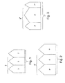
- Fig. 1 to 3 show schematically an energy flow within the circulation fluid system 11.
- the energy flow diagrams also referred to as Sankey diagrams, show the total electric energy 1, 1', 1" received by the circulation pump unit 11. This energy 1, 1', 1" can be transferred to the circulation fluid system 11 or the environment in various ways.
- a first amount of energy is transferred or passed as kinetic energy 3, 3', 3" from a pump 27 or a circulation pump unit 15 to the fluid 21.
- a second amount of energy is transferred as thermal energy to the fluid 21.
- the amount of this thermal energy 5, 5', 5" also referred to as an amount of waste heat, can be adjusted for example by suboptimal hydraulic or electric operation of the circulation pump unit 15.
- the second amount of energy can be supplied to the circulation line 13 or the fluid 21 located therein for example by targeted heat transfer from the pump motor 29 or the frequency converter 31.
- a third amount of energy of the energy 1, 1', 1" received by the circulation pump unit 15 or available to the circulation pump unit 15 is transferred as thermal energy 7, 7', 7" to the ambient air.
- the amount of the kinetic energy 3, 3', 3" transferred to the fluid 21 can remain constant or be varied.
- the total energy 1, 1', 1" available to the circulation pump unit 15 can be changed and in particular increased.
- the total electric energy 1' received by the circulation pump unit 15 in Fig. 2 is greater than the energy 1 received in Fig. 1 .
- the electric energy 1" received by the circulation pump unit 15 in the embodiment of Fig. 3 is greater than in Fig. 1 .
- the amount of the electric energy received by the circulation pump unit 15 can be increased, for example by suboptimal electric and/or suboptimal hydraulic operation of the circulation pump unit 15.
- the circulation pump unit 15 is operated in the optimal electric and hydraulic range in the embodiment of Fig. 1 and in the suboptimal range in Fig. 2 and 3 .
- the amount of the thermal energy transferred to the fluid 21 can be increased.
- This amount of waste heat 5, 5', 5" can be increased, for example by shifting the ratio between the thermal energy transferred to the environment and the thermal energy transferred to the fluid 21.
- the energy 1' available to the circulation pump unit 15 overall in Fig. 2 is equal to the energy 1" available overall in Fig. 3 .
- more thermal energy 5" is transferred to the fluid 21 than in Fig. 2 .
- less thermal energy 7" is transferred to the environment or to the ambient air than in Fig. 2 .
- control unit 17 can control the operation of the circulation pump unit 15 in the suboptimal electric and/or hydraulic range in such a way that overall more thermal energy 5, 5', 5" is transferred to the fluid or to the pipeline system and less thermal energy 7, 7', 7" is transferred to the environment.
- the energy 9, 9', 9" supplied to the fluid 21 overall is made up of the kinetic energy 3, 3', 3" and the thermal energy 5, 5', 5". As shown in Fig. 2 , this energy 9, 9', 9" can on one hand be increased by increasing the total amount of the energy 1, 1', 1" available to the circulation pump unit 15.
- the energy 9, 9', 9" supplied to the fluid 21 overall can be increased by increasing the thermal energy 5, 5', 5" transferred to the fluid at the expense of the thermal energy 7, 7', 7" transferred to the ambient air.
- the control unit 17 controls various parameters of the circulation fluid system 11.
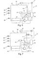
- Fig. 4 to 7 show different configurations of the circulation fluid system 11, which are based on different principles for controlling and producing the amount of energy 9, 9', 9" which can be transferred to the fluid 21 overall and in particular the transferrable amount of thermal energy 5, 5', 5".
- Fig. 4 shows a circulation fluid system 11 with temperature control by thermally optimised operation of a circulation pump unit 15.
- the circulation fluid system 11 is designed as a drinking water system in an aircraft.
- the circulation fluid system 11 is thus suitable for movable application.
- the circulation fluid system 11 comprises a circulation line 13 which, together with a circulation pump unit 15, forms a circulation circuit 19.
- the circulation line 13 may for example consist of pipes and also comprise a holding tank 39.
- the circulation pump unit 15 comprises a pump 27, for example a centrifugal pump, which causes an increase in pressure and circulation of the fluid 21 located in the circulation circuit 19.
- the fluid 21 is conveyed to one or more extraction points 25 where it can be extracted. Excess fluid is returned to the holding tank 39 via the circulation line 13. If, for example, no drinking water is extracted at the extraction points 25, all the drinking water is returned to the holding tank 39 via the circulation line 13.
- a second valve 41 which is designed for example as a throttle, can be integrated in the circulation line 13.
- the circulation pump unit 15 comprises a pump motor 29 and a frequency converter 31.
- the frequency converter 31 can convert a variable voltage provided on board an aircraft into a voltage which is suitable for operation of the pump motor 29.
- the control unit 17 can for example adjust the rotational speed of the pump 27 via a rotational speed or power of the pump motor 29.
- Heat sinks 45 can be present in certain regions of the circulation line 13. These heat sinks can occur for example in a drinking water system of an aircraft because the pipelines pass for example in the vicinity of an outer skin of the aircraft.
- the circulation fluid system 11 must thus be heated intermittently or continuously in order to ensure the fluid 21 is protected from freezing.
- a system temperature should be kept above the freezing temperature of the fluid, in particular for example approximately 6-10 °C.
- a hygienically advantageous temperature is provided, such that microbial contamination can be avoided.
- a temperature of for example approximately 12-16 °C should not be exceeded.
- the circulation fluid system 11 is configured for transferring a scalable amount of energy to the fluid 21.
- the circulation fluid system 11 comprises a control unit 17 which is in connected to the individual system components and controls individual parameters in such a way that the amount of energy 9, 9', 9" transferred to the fluid 21, and in particular the amount of thermal energy 5, 5', 5", adjusts the temperature of the fluid 21 to a predeterminable temperature setpoint value.
- a temperature sensor 23 is provided in the circulation fluid system 11, is connected to the control unit 17 and transmits thereto a current temperature value of the fluid.
- the control unit 17 compares the current temperature value with a temperature setpoint value and adapts the parameters of the system accordingly.
- the parameters are adapted in such a way that the circulation pump unit 15 is operated in a hydraulically or electrically suboptimal range.
- a hydraulic short circuit is connected in the circulation pump unit 15 for this purpose.
- the hydraulic short circuit is designed as a bypass conduit 33 comprising a first valve 35.
- a particular first quantity of fluid at the pump 27 is carried in the short circuit directly from the pump outlet to the pump inlet.
- the hydraulic power of the pump unit 15 decreases as a result.
- the rotational speed of the pump 27 must be increased. Consequently, the pump head for example is heated such that an amount of energy 9, 9', 9", in particular an amount of thermal energy 5, 5', 5", can be transferred to the fluid 21.
- the first valve 35 may have a changeable flow cross-section.
- the amount of energy 9, 9', 9" which can be transferred to the fluid can also be controlled by controlling the first flow rate by the first valve 35.
- the control unit 17 is in contact with the circulation pump unit 15 and with the first valve 35.
- Fig. 5 shows an alternative possibility for adjusting the transferrable amount of energy 9, 9', 9" and in particular the transferrable amount of thermal energy 5, 5', 5".
- the transferrable amount of energy 9, 9', 9" is adjusted by selecting a suboptimal operating point of the pump motor 29 or of the frequency converter 31 of the circulation pump unit 15. Therein, the electric efficiency of the motor 29 is influenced, for example.
- the control unit 17 is connected to the circulation pump unit 15 and in particular to the frequency converter 31.
- the control unit 17 can actuate the frequency converter 31 at a predeterminable, sometimes also variable, input frequency in such a way that the frequency converter operates in an electrically suboptimal operating state and thus produces heat.
- This heat can be received for example by a cooling system and transferred to the fluid 21 by a heat exchanger 37 which is provided in the circulation pump unit 15, or, as in the case of a pump motor flooded with the fluid, transferred from the motor windings to the fluid (as for example in the case of a canned motor pump).
- the control unit 17 controls the amount of energy 9, 9', 9" which can be transferred to the fluid, and in particular the transferrable amount of thermal energy 5, 5', 5", by a change in the set pressure of the system or by a change in the rotational speed of the pump 27.
- the circulation line 13 is provided with a pressure sensor 47 which is configured for transmitting a current system pressure to the control unit 17.
- the second valve 41 provided in the circulation line 13 has a smaller flow cross-section than the circulation line 13.
- a flow cross-section of the second valve 41 is changed.
- a valve motor 43 is connected to the second valve 41.
- the valve motor 43 can be actuated via the control unit 17. If, for example, the flow cross-section of the second valve 41 is enlarged, the rotational speed of the pump and the volume flow must be increased in order to keep the outlet pressure at the pump 27 constant. That is to say, the larger the throttle cross-section at the valve 41, the higher the hydraulic and thus thermal power transferred to the fluid 21, and the greater the energy 9, 9', 9" introduced into the system overall.
- the pump 27, which is designed for example as a centrifugal pump, transfers more energy 9, 9', 9" overall to the fluid 21 located in the circulation line 13, and prevents the system from freezing.
- the circulation pump unit 15 can be adjusted towards optimum pressure production, such that overall less energy 9, 9', 9" is transferred into the circulation line 13 or to the fluid 21 located therein.
- equalisation between the heat source, specifically the circulation pump unit 15, and heat sinks 45 can be achieved such that a system temperature can in general reliably be kept above the freezing point and below a temperature range of from 12 to 16 °C.
Landscapes
- Engineering & Computer Science (AREA)
- Physics & Mathematics (AREA)
- Thermal Sciences (AREA)
- Chemical & Material Sciences (AREA)
- Combustion & Propulsion (AREA)
- Mechanical Engineering (AREA)
- General Engineering & Computer Science (AREA)
- Aviation & Aerospace Engineering (AREA)
- Steam Or Hot-Water Central Heating Systems (AREA)
- Structures Of Non-Positive Displacement Pumps (AREA)
- Control Of Positive-Displacement Pumps (AREA)
- Control Of Temperature (AREA)
Abstract
Description
- This application claims the benefit of the filing date of German Patent Application No.
10 2011 106 177.4 filed June 30, 2011 and of United States Provisional Patent Application No.61/503,384 filed June 30, 2011 - The present invention relates to a circulation fluid system with temperature control by thermally optimised operation of a circulation pump, to a corresponding method for thermal optimisation of a circulation fluid system and to an aircraft comprising a circulation fluid system.
- Temperature control of a fluid system can be important in stationary and in movable arrangements. For example, controlling the temperature of a drinking water system on board an aircraft can be important for the comfort and safety of the passengers. On one hand, the drinking water must be heated in order to ensure protection against freezing. On the other hand, the water must not be too warm, in order to avoid accumulation and propagation of germs.
- A protection against freezing for a drinking water system of an aircraft can for example be ensured by electric pipe trace heaters, which are arranged for example in a sleeve-like manner around a drinking water pipe. For example, electric heaters for drinking water systems are known from
DE 103 13 876 A1 . However, electric pipe trace heaters can require a lot of work during installation and a lot of maintenance. - In addition, water systems comprising a pump which causes circulation of the water in the system and in this way prevents stagnation of the water are known for example from
US 6,766,822 B2 . The kinetic energy transferred to the water can help to prevent the water from freezing. However, if the outside temperature of the system is below a particular value, the kinetic energy cannot prevent freezing. In addition, when an outside temperature of the system is comparatively high, the kinetic energy additionally transferred to the water can promote contamination of the water. - There may therefore be a need for improved controlled and reliable temperature control of a circulation fluid system.
- This object can be achieved by the subject matter of the invention according to the independent claims. Advantageous embodiments of the invention are described in the dependent claims.
- According to a first aspect of the invention, a thermally optimised circulation fluid system is described. The circulation fluid system comprises a circulation line. A circulation pump unit and the circulation line together form a circulation circuit. The circulation pump unit is configured for transferring an amount of thermal energy directly and/or indirectly to a fluid located in the circulation line. In addition, the control unit is configured for adjusting the amount of thermal energy which is transferrable to the fluid.
- In other words, the idea of the present invention is based on adjusting or scaling an amount of energy which can be transferred from the circulation pump unit to the pipeline system or to the fluid. For this purpose, the control unit can change various parameters of the system. The amount of energy which is transferrable to the fluid or to the pipeline system can be produced for example by suboptimal hydraulic or electric operation of the circulation pump unit. For example, the rotational speed of a pump, the efficiency of a frequency converter of the pump, or the flow cross-section of a valve in the line of the system can be changed. At this, the control unit can for example regulate a relationship between a hydraulic power of the pump and the waste heat produced by the pump. Alternatively or additionally, the energy consumption of the pump can be changed, in particular increased. This can be done for example by electrically suboptimal operation of the electric pump drive.
- In this way, initially undesirable heating of a circulation pump can be caused at the right time and transferred as waste heat to a fluid located in the system. The heating of the circulation pump is thus advantageously used synergetically for temperature control. In other words, the circulation pump already provided in the system can be used synergetically, not only for increasing pressure and for circulation, but also for heating parts of the pipe installation, in particular of the circulation line.
- As a result, there is no longer a need for conventional pipe heating by known pipe heaters such as strip heaters, together with the electric installations and control technology required for these, for example cables, plugs, sensors, controllers, etc. In this way, on the one hand a cabling expenditure does not apply and on the other hand weight is saved. A further advantage of the circulation fluid system according to the invention is the higher level of failure safety and simpler configuration management compared to known pipe heating systems.
- By the circulation fluid system according to the invention, equalisation between the circulation pump as heat source and heat sinks, for example at pipelines, can be achieved, such that a system temperature of the fluid of for example approximately 6-10 °C can be maintained as long as the ambient temperatures of the water system are not generally higher. This temperature range ensures protection against freezing. In contrast to previously known systems, in this case it is possible to influence the actual state or the current state. This can for example be particularly advantageous if, for example, drinking water pipes are guided through regions in which the average temperature level is below approximately 6 °C.
- In addition, the circulation fluid system according to the invention can prevent the system being heated to a relatively high temperature of for example over 16 °C. Heating of this type could lead to contamination of the system and infringe hygiene regulations. By the system according to the invention, an uncontrolled heat transfer is avoided and contamination is thus prevented. In other words, by the system according to the invention, a hygienically advantageous temperature level can be provided and maintained in a controlled manner.
- The thermally optimised circulation fluid system may be for example a movable system in a vehicle or an aircraft. The fluid may be a liquid substance. For example, the circulation fluid system may be designed as a water system, in particular a drinking water system of an aircraft.
- The circulation line provided in the system comprises, for example, pipes which, in a stationary system, form a circuit having an additional fluid supply and, in a movable system, may also comprise a reservoir or a holding tank. The circulation line may comprise one or more extraction points at which fluid can be extracted from the system.
- The circulation pump unit is configured for circulating the fluid and to increase a pressure of the fluid in the system. The circulation pump unit may comprise a pump, a motor for operating the pump, and a frequency converter for supplying the motor with a corresponding voltage. The pump may for example be a positive-displacement pump or a flow pump or a centrifugal pump.
- The circulation pump unit is in fluid communication with the circulation line and together therewith forms a circulation circuit. For this purpose, the circulation pump unit may for example be integrated into the circulation line.
- The circulation pump unit is supplied with a total amount of energy which the circulation pump unit can transfer in various ways. Part of the energy can be transferred to the fluid in the circulation system and a further part can be transferred for example to the ambient air. Part of the transferred energy is transferred to the fluid in the form of kinetic energy by the movement of the pump. The kinetic energy is converted into thermal energy by dissipation, partly in the pump itself and within the circulation system. This dissipation energy is proportional to the hydraulic power of the pump. A further portion of the energy transferred by the circulation pump unit may be transferred in the form of thermal energy, also referred to as waste heat. The waste heat can be divided into two different portions: on one hand the portion transferred to the ambient air and on the other hand a heat portion which can be transferred to the fluid of the system for example by suboptimal hydraulic or electric operation. Overall, the amount of energy which can be transferred from the circulation pump unit to the fluid or to the circulation system is the difference between the (electric) energy supplied to the circulation pump unit and the energy portion transferred from the circulation pump unit to the ambient air. This controllable amount of energy is adjusted by the control unit.
- The amount of thermal energy received by the circulation system can either be received by the fluid directly as waste heat of the circulation pump unit or received indirectly as kinetic energy and converted into thermal energy ("heat") within the circulation system by dissipation. A heat transfer directly at the circulation pump unit may occur for example owing to heating of a frequency converter in the circulation pump unit. Additionally or alternatively, heat can be transferred directly at the motor windings. This is possible for example when using a flooded pump. In this case, the pump motor may be designed for example as a canned motor.
- An indirect heat transfer by the circulation pump unit may occur in that a pressure of the fluid in the system is increased, for example by an increase in the rotational speed of the pump. An indirect heat transfer by the circulation pump unit may occur in that a flow cross-section of a valve arranged in the circulation line is increased such that, for the same pressure at the pump outlet, there is a greater volume flow through the system and thus more energy is introduced into the system or released as (dissipation) heat in the system.
- The control unit may for example be a processing unit, for example a CPU (central processing unit). It may be connected electrically and functionally to the individual system components, such as circulation pump unit, pump, frequency converter, pump motor, valves, and temperature and pressure sensors.
- According to an embodiment of the invention, the control unit is configured for adjusting the transferrable amount of thermal energy by operating the circulation pump unit in a hydraulically and/or electrically suboptimal range.
- According to a further embodiment of the invention, the control unit is configured for adjusting a temperature of the fluid to a predeterminable temperature setpoint value via the adjustable amount of thermal energy. For this purpose, according to a further embodiment of the invention, a temperature sensor can be provided in the circulation fluid system. The temperature sensor is configured for determining a current temperature value of the fluid. Furthermore, the control unit is configured for comparing the current temperature value with the predeterminable temperature setpoint value.
- The temperature sensor may be connected to the control device and provided directly in or at the circulation line. The temperature sensor may be configured for determine a temperature value which represents the current temperature of the fluid in the circulation line. For example, the temperature sensor may be arranged at or downstream of a heat sink, such that the lowest temperature in the system is determined. Furthermore, a plurality of temperature sensors may be provided in the circulation fluid system.
- The determined current temperature value is compared with a predeterminable temperature setpoint value. The temperature setpoint value can for example be predefined automatically by the control device or alternatively can be adjusted by a user. Depending on the difference between the currently determined temperature value and the temperature setpoint value, the control unit changes the amount of thermal energy which is transferred from the circulation pump unit to the fluid. In this way, the temperature of the fluid can be controlled. Thus, the amount of thermal energy is adjusted on the basis of the deviation of the current temperature value from the temperature setpoint value.
- According to a further embodiment of the invention, the circulation pump unit comprises a bypass conduit and a pump. The bypass conduit is configured for diverting a first quantity of fluid from the circulation circuit past the pump. The control unit is configured for adjusting the transferrable amount of thermal energy by controlling the rotational speed of the pump.
- The pump may be designed for example as a flow pump, in particular as a centrifugal pump. The bypass conduit may be for example a bore in the hydraulic conduit of the pump. The bore may have for example a variable diameter. Alternatively, the diameter may be constant. This embodiment corresponds to a hydraulic short circuit of the pump. In order to maintain the same hydraulic power, the rotational speed of the pump must be increased. By increasing the rotational speed of the pump at the same hydraulic power of the circulation pump unit, more energy can for example be transferred to the fluid. This occurs for example owing to heating of the pump head which is in contact with the fluid and owing to the additional energy dissipation occurring in the bypass conduit and in the pump. Thus, in this embodiment, the increased energy transfer occurs owing to increased energy dissipation into heat directly in the circulation pump unit and in particular the pump contained therein.
- According to a further embodiment of the invention, the bypass conduit comprises a first valve. The control unit is configured for adjusting the transferrable amount of thermal energy by controlling the first quantity of fluid. The control unit is designed configured for adjusting the first quantity of fluid by controlling the first valve.
- The first valve may be for example a throttle having a changeable flow cross-section. In addition to adjusting the rotational speed of the pump, the first valve can be regulated in such a way that an optimum amount of energy is transferred to the fluid.
- According to a further embodiment of the invention, a frequency converter is provided in the circulation pump unit. The control unit is configured for actuating the frequency converter in such a way that said converter influences the transferrable amount of thermal energy in a targeted manner.
- The frequency converter may for example produce, from a voltage provided by a supplier, such as a line voltage, or on board an aircraft, a voltage which is suitable for driving a motor of the pump. For example, the frequency converter may be configured for providing a voltage which is changeable in amplitude and frequency. Alternatively, the frequency converter may be configured for providing a pulsed direct voltage. The frequency converter may be actuated by the control unit in such a way that, at a constant rotational speed of the pump and the motor, the frequency converter is operated at a suboptimal operational level and thus produces more heat. This heat may be transferred for example through the housing of the frequency converter to the environment and thus to the fluid located in the circulation fluid system. The frequency converter may also be controlled in such a way that the motor windings transfer a greater amount of waste heat at the same rotational speed. In this way, more heat can be transferred directly from the motor windings to the fluid. In this way, in this embodiment, the increased energy transfer occurs through direct heat transfer from the circulation pump unit to the fluid.
- According to a further embodiment of the invention, a heat exchanger is also arranged in the circulation pump unit. This heat exchanger is configured for transferring the predeterminable amount of thermal energy from the frequency converter to the fluid.
- For this purpose, a cooling system may be provided for example around the housing of the frequency converter. The cooling system receives the waste heat of the frequency converter and passes it on to the heat exchanger, which is in communication with the fluid.
- According to a further embodiment of the invention, a pump motor having motor windings is also provided in the circulation pump unit. The control unit is configured for actuating the pump motor in such a way that the pump motor produces the predeterminable amount of thermal energy. The motor windings are configured for transferring the predeterminable amount of thermal energy to the fluid.
- According to a further embodiment of the invention, a pump is provided in the circulation pump unit. A second valve is also provided in the circulation line. The control unit is configured for adjusting the transferred amount of energy by controlling the rotational speed of the pump at a constant pressure of the fluid at the outlet of the pump through the second valve. The constant pressure may be a predeterminable set pressure.
- The circulation line comprises a particular first cross-section which may be constant or variable. The second valve, which is designed for example as a throttle, comprises a second cross-section which is smaller than the first cross-section. The cross-section of the valve can also be referred to as a flow cross-section. In this embodiment, the second cross-section is variable. For this purpose, a motor for example may be connected to the second valve.
- In this embodiment, the energy input is increased owing to the increased volume flow which results when the cross-section of the second valve is enlarged and the pressure in the fluid at the outlet of the pump is kept constant. In this embodiment, the increased amount of energy which is received owing to increased dissipation within the circulation system is thus converted into thermal energy and thus more heat is transferred indirectly from the circulation pump unit to the fluid.
- According to a further embodiment of the invention, a pump is provided in the circulation pump unit. A second valve is also provided in the circulation line. The control unit is configured for adjusting the transferrable amount of thermal energy by controlling the rotational speed of the pump at a constant flow rate of the fluid through the second valve.
- The circulation line has a particular first cross-section which may be constant or variable. The second valve, which is designed for example as a throttle, has a second cross-section which is smaller than the first cross-section. The cross-section of the valve can also be referred to as a flow cross-section. The flow cross-section is directly proportional to the flow rate of the fluid. In this embodiment, the second cross-section is constant.
- The control unit may determine a current pressure for example via one or more pressure sensors in the circulation line. By increasing the rotational speed of the pump, a greater kinetic energy and a higher pressure can be transferred to the fluid.
- Owing to the smaller cross-section, there is a narrowing at the second valve such that more kinetic energy of the fluid is converted into heat. In this embodiment, the increased amount of energy received by the circulation pump unit owing to increased dissipation within the circulation system is thus converted into thermal energy and more heat is transferred indirectly from the circulation pump unit to the fluid.
- According to a further embodiment of the invention, a pump is provided in the circulation pump unit. The circulation line also comprises a second valve. The control unit is configured for adjusting the transferrable amount of waste heat by controlling the flow rate of the fluid through the second valve at a constant rotational speed of the pump.
- In this embodiment, the increased waste heat is likewise transferred indirectly from the circulation pump unit to the fluid. In contrast to the previous embodiment, the rotational speed of the pump remains constant, while the flow cross-section of the second valve can be varied by the control unit. For this purpose, a motor for example may be connected to the second valve. The control unit can control the flow cross-section of the second valve via the motor. The more the valve is closed, thus the more the flow cross-section decreases, the more waste heat is transferred to the fluid at the valve.
- Alternatively, the control unit may adjust the rotational speed of the pump and also the flow rate of the fluid through the second valve.
- According to a second aspect of the invention, a method for thermal optimisation of an above-described circulation fluid system is described. The method comprises the following steps: determining a current temperature value of a fluid located in the circulation fluid system; comparing the current temperature value with the predeterminable temperature setpoint value; adjusting, by a control unit, an amount of waste heat which can be transferred to the fluid by a circulation pump unit; the amount of waste heat being adjusted on the basis of a deviation of the current temperature value from the temperature setpoint value.
- According to an embodiment of the invention, the method further comprises producing the amount of waste heat by operating the circulation pump unit in a hydraulically and/or electrically suboptimal range.
- According to a further embodiment of the invention, adjusting the transferrable amount of waste heat comprises increasing a rotational speed of a pump of the circulation pump unit.
- According to a third aspect of the invention, an aircraft is described which comprises an above-described circulation fluid system and a fluid holding tank. The fluid holding tank, the circulation pump unit and the circulation line can together form a circulation circuit. The fluid holding tank may for example be designed as part of the circulation line or be integrated into it. Alternatively, the fluid holding tank may be arranged outside the circulation line and be connected to the circulation circuit for example by a line.
- According to an embodiment of the invention, the circulation fluid system is designed as a drinking water system of the aircraft.
- Further features and advantages of the invention will become apparent to a person skilled in the art from the following description of exemplary embodiments - which, however, are not to be interpreted as limiting the invention - with reference to the enclosed drawings.
-
- Fig. 1
- shows schematically an energy flow diagram of the circulation fluid system according to the invention in the case of a first adjustment by the control unit;
- Fig. 2
- shows schematically an energy flow diagram of the circulation fluid system according to the invention in the case of a second adjustment by the control unit;
- Fig. 3
- shows schematically an energy flow diagram of the circulation fluid system according to the invention in the case of a third adjustment by the control unit;
- Fig. 4
- shows a circulation fluid system in which, in a first embodiment of the invention, an amount of waste heat which is transferrable to the fluid is adjusted by a hydraulic short circuit of the pump;
- Fig. 5
- shows a circulation fluid system in which, according to a further embodiment of the invention, an amount of waste heat which can be transferred to the fluid is adjusted by electrically suboptimal operation of the frequency converter of the pump or of the pump motor;
- Fig. 6
- shows a circulation fluid system in which, according to a further embodiment of the invention, an amount of waste heat which is transferrable to the fluid is adjusted by an increase in the rotational speed of the pump;
- Fig. 7
- shows a circulation fluid system in which, according to a further embodiment of the invention, an amount of waste heat which is transferrable to the fluid is adjusted by a variation in the flow cross-section of a second valve.
- All the figures are merely schematic views of devices according to the invention and of the components thereof. In particular, spacings and dimensional relationships are not reproduced to scale in the figures. In the various figures, same or identical elements are provided with the same reference numerals.
-
Fig. 1 to 3 show schematically an energy flow within thecirculation fluid system 11. The energy flow diagrams, also referred to as Sankey diagrams, show the totalelectric energy circulation pump unit 11. Thisenergy circulation fluid system 11 or the environment in various ways. - A first amount of energy is transferred or passed as
kinetic energy pump 27 or acirculation pump unit 15 to thefluid 21. A second amount of energy is transferred as thermal energy to thefluid 21. The amount of thisthermal energy circulation pump unit 15. The second amount of energy can be supplied to thecirculation line 13 or the fluid 21 located therein for example by targeted heat transfer from thepump motor 29 or thefrequency converter 31. A third amount of energy of theenergy circulation pump unit 15 or available to thecirculation pump unit 15 is transferred asthermal energy kinetic energy - The
total energy circulation pump unit 15 can be changed and in particular increased. For example, the total electric energy 1' received by thecirculation pump unit 15 inFig. 2 is greater than theenergy 1 received inFig. 1 . In addition, theelectric energy 1" received by thecirculation pump unit 15 in the embodiment ofFig. 3 is greater than inFig. 1 . The amount of the electric energy received by thecirculation pump unit 15 can be increased, for example by suboptimal electric and/or suboptimal hydraulic operation of thecirculation pump unit 15. For example, thecirculation pump unit 15 is operated in the optimal electric and hydraulic range in the embodiment ofFig. 1 and in the suboptimal range inFig. 2 and 3 . - Additionally or alternatively, to increasing the total amount of energy available to the
circulation pump unit 15, the amount of the thermal energy transferred to the fluid 21 can be increased. This amount ofwaste heat fluid 21. For example, the energy 1' available to thecirculation pump unit 15 overall inFig. 2 is equal to theenergy 1" available overall inFig. 3 . However, inFig. 3 morethermal energy 5" is transferred to the fluid 21 than inFig. 2 . For this purpose, inFig. 3 lessthermal energy 7" is transferred to the environment or to the ambient air than inFig. 2 . In other words, thecontrol unit 17 can control the operation of thecirculation pump unit 15 in the suboptimal electric and/or hydraulic range in such a way that overall morethermal energy thermal energy energy kinetic energy thermal energy Fig. 2 , thisenergy energy circulation pump unit 15. On the other hand, theenergy thermal energy thermal energy energy control unit 17 controls various parameters of thecirculation fluid system 11. -
Fig. 4 to 7 show different configurations of thecirculation fluid system 11, which are based on different principles for controlling and producing the amount ofenergy thermal energy -
Fig. 4 shows acirculation fluid system 11 with temperature control by thermally optimised operation of acirculation pump unit 15. Thecirculation fluid system 11 is designed as a drinking water system in an aircraft. Thecirculation fluid system 11 is thus suitable for movable application. - The
circulation fluid system 11 comprises acirculation line 13 which, together with acirculation pump unit 15, forms acirculation circuit 19. Thecirculation line 13 may for example consist of pipes and also comprise aholding tank 39. Thecirculation pump unit 15 comprises apump 27, for example a centrifugal pump, which causes an increase in pressure and circulation of the fluid 21 located in thecirculation circuit 19. The fluid 21 is conveyed to one or more extraction points 25 where it can be extracted. Excess fluid is returned to the holdingtank 39 via thecirculation line 13. If, for example, no drinking water is extracted at the extraction points 25, all the drinking water is returned to the holdingtank 39 via thecirculation line 13. In order to maintain an admission pressure, asecond valve 41, which is designed for example as a throttle, can be integrated in thecirculation line 13. - In addition to the
pump 27, thecirculation pump unit 15 comprises apump motor 29 and afrequency converter 31. Thefrequency converter 31 can convert a variable voltage provided on board an aircraft into a voltage which is suitable for operation of thepump motor 29. Thecontrol unit 17 can for example adjust the rotational speed of thepump 27 via a rotational speed or power of thepump motor 29. - Heat sinks 45 can be present in certain regions of the
circulation line 13. These heat sinks can occur for example in a drinking water system of an aircraft because the pipelines pass for example in the vicinity of an outer skin of the aircraft. Thecirculation fluid system 11 must thus be heated intermittently or continuously in order to ensure the fluid 21 is protected from freezing. For this purpose, a system temperature should be kept above the freezing temperature of the fluid, in particular for example approximately 6-10 °C. In addition, it must be ensured that a hygienically advantageous temperature is provided, such that microbial contamination can be avoided. For this purpose, a temperature of for example approximately 12-16 °C should not be exceeded. - The
circulation fluid system 11 according to the invention is configured for transferring a scalable amount of energy to thefluid 21. In this way, protection against freezing can be ensured and too high a temperature can be avoided. For this purpose, thecirculation fluid system 11 comprises acontrol unit 17 which is in connected to the individual system components and controls individual parameters in such a way that the amount ofenergy thermal energy temperature sensor 23 is provided in thecirculation fluid system 11, is connected to thecontrol unit 17 and transmits thereto a current temperature value of the fluid. Thecontrol unit 17 compares the current temperature value with a temperature setpoint value and adapts the parameters of the system accordingly. The parameters are adapted in such a way that thecirculation pump unit 15 is operated in a hydraulically or electrically suboptimal range. - In
Fig. 4 , a hydraulic short circuit is connected in thecirculation pump unit 15 for this purpose. In the embodiment, the hydraulic short circuit is designed as abypass conduit 33 comprising afirst valve 35. In the case of a constant cross-section of thefirst valve 35, a particular first quantity of fluid at thepump 27 is carried in the short circuit directly from the pump outlet to the pump inlet. The hydraulic power of thepump unit 15 decreases as a result. In order to maintain the hydraulic power of thepump unit 15, the rotational speed of thepump 27 must be increased. Consequently, the pump head for example is heated such that an amount ofenergy thermal energy fluid 21. In addition, thefirst valve 35 may have a changeable flow cross-section. The amount ofenergy first valve 35. For this purpose, thecontrol unit 17 is in contact with thecirculation pump unit 15 and with thefirst valve 35. -
Fig. 5 shows an alternative possibility for adjusting the transferrable amount ofenergy thermal energy Fig. 5 , the transferrable amount ofenergy pump motor 29 or of thefrequency converter 31 of thecirculation pump unit 15. Therein, the electric efficiency of themotor 29 is influenced, for example. Thecontrol unit 17 is connected to thecirculation pump unit 15 and in particular to thefrequency converter 31. Thecontrol unit 17 can actuate thefrequency converter 31 at a predeterminable, sometimes also variable, input frequency in such a way that the frequency converter operates in an electrically suboptimal operating state and thus produces heat. This heat can be received for example by a cooling system and transferred to the fluid 21 by aheat exchanger 37 which is provided in thecirculation pump unit 15, or, as in the case of a pump motor flooded with the fluid, transferred from the motor windings to the fluid (as for example in the case of a canned motor pump). - In the embodiment shown in
Fig. 6 , thecontrol unit 17 controls the amount ofenergy thermal energy pump 27. For this purpose, thecirculation line 13 is provided with apressure sensor 47 which is configured for transmitting a current system pressure to thecontrol unit 17. By actuating thecirculation pump unit 15, thecontrol unit 17 can increase the system pressure. Thesecond valve 41 provided in thecirculation line 13 has a smaller flow cross-section than thecirculation line 13. When the system pressure is increased or when the rotational speed of thepump 27 is increased,more energy circulation fluid system 11 overall. The higher the system pressure, the more heat is supplied to the system or released in the system by dissipation. - In
Fig. 7 , the current pressure is maintained by thecontrol unit 17 and for this purpose a flow cross-section of thesecond valve 41 is changed. For this purpose, avalve motor 43 is connected to thesecond valve 41. Thevalve motor 43 can be actuated via thecontrol unit 17. If, for example, the flow cross-section of thesecond valve 41 is enlarged, the rotational speed of the pump and the volume flow must be increased in order to keep the outlet pressure at thepump 27 constant. That is to say, the larger the throttle cross-section at thevalve 41, the higher the hydraulic and thus thermal power transferred to the fluid 21, and the greater theenergy - Thus, at suboptimal pressure production operation, the
pump 27, which is designed for example as a centrifugal pump, transfersmore energy circulation line 13, and prevents the system from freezing. In the event that there is excess heat and the temperature in thecirculation line 13 rises so much that hygiene could be impaired, thecirculation pump unit 15 can be adjusted towards optimum pressure production, such that overallless energy circulation line 13 or to the fluid 21 located therein. Overall, by the system according to the invention, equalisation between the heat source, specifically thecirculation pump unit 15, andheat sinks 45 can be achieved such that a system temperature can in general reliably be kept above the freezing point and below a temperature range of from 12 to 16 °C. - Finally, it is noted that expressions such as "comprising" or the like are not intended to exclude the possibility of further elements or steps being provided. Furthermore, it is noted that "a" or "an" do not exclude a plurality. In addition, features described in connection with the various embodiments can be combined as desired. It is also noted that the reference numerals in the claims are not to be interpreted as limiting the scope of the claims.
-
- 1
- total electric energy received by the circulation pump unit
- 3, 3', 3"
- kinetic energy (dissipation energy) transferred to fluid
- 5, 5', 5"
- thermal energy transferred to fluid
- 7, 7', 7"
- thermal energy transferred to ambient air
- 9, 9', 9"
- energy transferred to fluid overall
- 11
- circulation fluid system
- 13
- circulation line
- 15
- circulation pump unit
- 17
- control unit
- 19
- circulation circuit
- 21
- fluid
- 23
- temperature sensor
- 25
- extraction point
- 27
- pump
- 29
- pump motor
- 31
- frequency converter
- 33
- bypass conduit
- 35
- first valve
- 37
- heat exchanger
- 39
- holding tank
- 41
- second valve
- 43
- valve motor
- 45
- heat sink
- 47
- pressure sensor
Claims (15)
- Circulation fluid system (11), the circulation fluid system (11) comprising
a circulation line (13);
a circulation pump unit (15);
a control unit (17);
wherein the circulation pump unit (15) and the circulation line (13) together form a circulation circuit (19);
wherein the circulation pump unit (15) is configured for transferring an amount of thermal energy (5, 5', 5") directly and/or indirectly to a fluid (21) located in the circulation line (13);
wherein the control unit (17) is configured for adjusting the amount of thermal energy (5, 5', 5 ") which is transferrable to the fluid (21). - Circulation fluid system (11) according to claim 1,
wherein the control unit (17) is configured for adjusting the transferrable amount of thermal energy (5, 5', 5") by operating the circulation pump unit (15) in a hydraulically and/or electrically suboptimal range. - Circulation fluid system (11) according to any of claims 1 and 2,
wherein the control unit (17) is configured for adjusting a temperature of the fluid (21) to a predeterminable temperature setpoint value via the adjustable amount of thermal energy (5, 5', 5"). - Circulation fluid system (11) according to claim 3,
the circulation fluid system (11) further comprising a temperature sensor (23) which is configured for determining a current temperature value of the fluid (21);
wherein the control unit (17) is configured for comparing the current temperature value with the predeterminable temperature setpoint value. - Circulation fluid system according to any one of claims 1 to 4,
wherein a pump (27) and a bypass conduit (33) are provided in the circulation pump unit (15);
wherein the pump comprises a pump outlet and a pump inlet;
wherein the bypass conduit (33) is configured for carrying a first quantity of fluid from the circulation circuit (19) in a short circuit directly from the pump outlet to the pump inlet;
wherein the control unit (17) is configured for adjusting the transferrable amount of thermal energy (5, 5', 5") by controlling a rotational speed of the pump (27). - Circulation fluid system (11) according to claim 5,
wherein the bypass conduit (33) comprises a first valve (35);
wherein the control unit (17) is configured for adjusting the transferrable amount of thermal energy (5, 5', 5") by controlling the first quantity of fluid;
wherein the control unit (17) is configured for adjusting the first quantity of fluid by controlling the first valve (35). - Circulation fluid system (11) according to any one of claims 1 to 6,
wherein a frequency converter (31) is provided in the circulation pump unit (15);
wherein the control unit (17) is configured for actuating the frequency converter (31) in such a way that the frequency converter (31) produces the transferrable amount of thermal energy (5, 5', 5"). - Circulation fluid system (11) according to claim 7,
wherein a heat exchanger (37) is also provided in the circulation pump unit (15);
wherein the heat exchanger (37) is configured for transmitting the transferrable amount of thermal energy (5, 5', 5") from the frequency converter (31) to the fluid (21). - Circulation fluid system (11) according to any one of claims 1 to 4,
wherein a pump (27) is provided in the circulation pump unit (15);
wherein a second valve (41) is provided in the circulation line (13);
wherein the control unit (17) is configured for adjusting the transferrable amount of thermal energy (5, 5', 5") by controlling a rotational speed of the pump (27) at a constant set pressure (47) of the fluid (21) through the second valve (41). - Circulation fluid system according to any one of claims 1 to 4,
wherein a pump (27) is provided in the circulation pump unit (15);
wherein a second valve (41) is provided in the circulation line (13);
wherein the control unit (17) is configured for adjusting the transferrable amount of thermal energy (5, 5', 5") by controlling the flow rate of the fluid (21) through the second valve (41) at a constant rotational speed of the pump (27). - Method for thermal optimisation of a circulation fluid system (11) according to any one of claims 1 to 10, the method comprising the following steps:determining a current temperature value of a fluid (21) located in the circulation fluid system (11);comparing the current temperature value with a predeterminable temperature setpoint value;adjusting, by a control unit (17), an amount of thermal energy (5, 5', 5") which is transferrable to the fluid (21) by a circulation pump unit (15);wherein the transferrable amount of thermal energy (5, 5', 5") is adjusted on the basis of a deviation of the current temperature value from the temperature setpoint value.
- Method according to claim 11, further comprising
producing the amount of thermal energy (5, 5', 5") by operating the circulation pump unit (15) in a hydraulically and/or electrically suboptimal range. - Method according to any of claims 11 and 12,
wherein adjusting the transferrable amount of thermal energy further comprises increasing a rotational speed of a pump (27) of the circulation pump unit (15). - Aircraft, the aircraft comprising
a fluid holding tank (39);
a circulation fluid system (11) according to any one of claims 1 to 10, wherein the fluid holding tank (39), the circulation pump unit (15) and the circulation line (13) together form a circulation circuit (19). - Aircraft according to claim 14,
wherein the circulation fluid system (11) is designed as a drinking water system.
Applications Claiming Priority (2)
| Application Number | Priority Date | Filing Date | Title |
|---|---|---|---|
| US201161503384P | 2011-06-30 | 2011-06-30 | |
| DE102011106177.4A DE102011106177B4 (en) | 2011-06-30 | 2011-06-30 | Temperature control of a circulation fluid system through thermo-optimized operation of a circulation pump |
Publications (2)
| Publication Number | Publication Date |
|---|---|
| EP2541158A2 true EP2541158A2 (en) | 2013-01-02 |
| EP2541158A3 EP2541158A3 (en) | 2016-03-23 |
Family
ID=46397058
Family Applications (1)
| Application Number | Title | Priority Date | Filing Date |
|---|---|---|---|
| EP12174098.9A Withdrawn EP2541158A3 (en) | 2011-06-30 | 2012-06-28 | Temperature control of a circulation fluid system by thermally optimised operation of a circulation pump |
Country Status (3)
| Country | Link |
|---|---|
| US (1) | US9657954B2 (en) |
| EP (1) | EP2541158A3 (en) |
| DE (1) | DE102011106177B4 (en) |
Families Citing this family (6)
| Publication number | Priority date | Publication date | Assignee | Title |
|---|---|---|---|---|
| EP2863134B1 (en) * | 2013-10-15 | 2018-06-06 | Grundfos Holding A/S | Method for adjusting a heating curve |
| US10018366B2 (en) * | 2015-02-05 | 2018-07-10 | Intellihot, Inc. | Learning-based recirculation and temperature setpoint control system |
| CN109996987B (en) * | 2016-09-09 | 2021-06-18 | 恩文特服务有限责任公司 | Automatic Remelting Control System |
| EP3771644B1 (en) | 2019-07-29 | 2025-01-08 | General Electric Company | Vehicle heat exchanger system |
| DE102023104925A1 (en) * | 2023-02-28 | 2024-08-29 | Schaeffler Technologies AG & Co. KG | Battery heating method and fluid device |
| DE102024115966A1 (en) | 2024-06-07 | 2025-12-11 | Dr. Ing. H.C. F. Porsche Aktiengesellschaft | Battery-electric vehicle |
Citations (2)
| Publication number | Priority date | Publication date | Assignee | Title |
|---|---|---|---|---|
| US6766822B2 (en) | 1998-09-29 | 2004-07-27 | International Water-Guard Industries, Inc. | Method of water distribution and apparatus therefor |
| DE10313876A1 (en) | 2003-03-21 | 2004-11-25 | Airbus Deutschland Gmbh | Heater for fresh water supply in aircraft has tubular feed pipe with electrical heating element between insulating layers |
Family Cites Families (16)
| Publication number | Priority date | Publication date | Assignee | Title |
|---|---|---|---|---|
| GB2035541A (en) * | 1978-10-13 | 1980-06-18 | Lyons J | Improvements relating to fluid-heating units |
| EP0326688B1 (en) * | 1988-01-30 | 1991-11-27 | Maschinenfabrik Rieter Ag | Removal of heat from textile machines |
| US4945942A (en) * | 1989-09-29 | 1990-08-07 | Metlund Enterprises | Accelerated hot water delivery system |
| DE4010049C1 (en) * | 1990-03-29 | 1991-10-10 | Grundfos International A/S, Bjerringbro, Dk | Pump unit for heating or cooling circuit - uses frequency regulator to reduce rotation of pump motor upon detected overheating |
| US5303739A (en) * | 1991-09-30 | 1994-04-19 | Deutsche Aerospace Airbus Gmbh | Fresh water supply system for an aircraft |
| US5309938A (en) * | 1991-09-30 | 1994-05-10 | Deutsche Aerospace Airbus Gmbh | Fresh water supply system for an aircraft |
| DE4202719C2 (en) * | 1992-01-31 | 1993-11-04 | Deutsche Aerospace Airbus | WATER SYSTEM FOR AN AIRPLANE |
| DE19513059A1 (en) | 1995-04-07 | 1996-10-10 | Guenter Zellmann | Energy conversion appts. for generating heat or current esp. for domestic air-conditioning and warm water |
| US5709201A (en) * | 1995-10-03 | 1998-01-20 | Anser Thermal Technologies, Inc. | Method and apparatus for heating a liquid medium |
| DE19609939C1 (en) * | 1996-03-14 | 1997-09-11 | Daimler Benz Aerospace Airbus | Aircraft water system |
| CH689736A5 (en) | 1999-01-13 | 1999-09-30 | Technoswiss Ag | Heating amplification system for warming air, water, spaces etc. |
| DE10007088A1 (en) * | 2000-02-16 | 2001-08-23 | Wilo Gmbh | Control device for pump and valve |
| DE10318821B4 (en) * | 2003-04-16 | 2007-06-21 | Oliver Laing | Method for providing hot water in a service water installation and service water installation |
| US8720463B2 (en) * | 2005-12-13 | 2014-05-13 | Airbus Operations Gmbh | Shower system for aircraft |
| TWM329830U (en) * | 2007-09-14 | 2008-04-01 | Cooler Master Co Ltd | Alarm device and water-cooling heat dissipation alarm system |
| CA2686836C (en) * | 2008-12-01 | 2017-04-11 | International Water-Guard Industries, Inc. | Water distribution system with dual use water treatment unit |
-
2011
- 2011-06-30 DE DE102011106177.4A patent/DE102011106177B4/en not_active Expired - Fee Related
-
2012
- 2012-06-28 EP EP12174098.9A patent/EP2541158A3/en not_active Withdrawn
- 2012-07-02 US US13/539,592 patent/US9657954B2/en not_active Expired - Fee Related
Patent Citations (2)
| Publication number | Priority date | Publication date | Assignee | Title |
|---|---|---|---|---|
| US6766822B2 (en) | 1998-09-29 | 2004-07-27 | International Water-Guard Industries, Inc. | Method of water distribution and apparatus therefor |
| DE10313876A1 (en) | 2003-03-21 | 2004-11-25 | Airbus Deutschland Gmbh | Heater for fresh water supply in aircraft has tubular feed pipe with electrical heating element between insulating layers |
Also Published As
| Publication number | Publication date |
|---|---|
| US9657954B2 (en) | 2017-05-23 |
| US20130000732A1 (en) | 2013-01-03 |
| EP2541158A3 (en) | 2016-03-23 |
| DE102011106177A1 (en) | 2013-01-03 |
| DE102011106177B4 (en) | 2021-11-25 |
Similar Documents
| Publication | Publication Date | Title |
|---|---|---|
| US9657954B2 (en) | Temperature control of a circulation fluid system by thermally optimised operation of a circulation pump | |
| RU2012143562A (en) | COOLING CIRCUIT OF THE COOLING OF THE INTERNAL COMBUSTION ENGINE WITH LIQUID COOLING | |
| US10184671B2 (en) | Method for limiting a supply flow in a heat transfer system | |
| CN106808658B (en) | Temperature control device | |
| DK3037704T3 (en) | Mixing valve | |
| KR20070037319A (en) | Constant temperature liquid circulation device and temperature control method in the device | |
| EP2333268A3 (en) | Cooling system for engine | |
| CN104405731B (en) | Hydraulic oil liquid heating system | |
| EP2587171B1 (en) | Method of controlling a variable delivery pump fitted to a heating system | |
| RU2425292C1 (en) | Adaptive control system of actuators of heat supply objects of municipal housing economy | |
| KR100869734B1 (en) | Constant temperature liquid circulating device having piping protecting function | |
| CN109790983A (en) | Heating system | |
| KR101375713B1 (en) | Temperature control apparatus for mold] | |
| EP2696061A1 (en) | Output controller for stirling engine | |
| WO2016151040A1 (en) | Heat exchange system | |
| DE602004025055D1 (en) | SYSTEM FOR CONTROLLING THE HEAT ENERGY OF A MOTOR VEHICLE MOTOR BY ADJUSTING THE FLUID DRIVE OF THE SYSTEM | |
| CN109799854B (en) | Cooling device and control method thereof | |
| SE1251186A1 (en) | Method and apparatus for regulating the indoor temperature of a property | |
| WO2009037775A1 (en) | Device and method for controlling temperature of fluid | |
| CN205225420U (en) | New energy automobile cooling system | |
| CA2770303A1 (en) | Dual functional temperature control system applicator system | |
| RU2427762C1 (en) | Entrance point of system for heat supply of building | |
| EP3181456B1 (en) | Aircraft heat exchange system including a thermoelectric device | |
| US9914545B2 (en) | Aircraft heat exchange system including a thermoelectric device | |
| EP2453180B1 (en) | Heating system with sensor accelerator |
Legal Events
| Date | Code | Title | Description |
|---|---|---|---|
| PUAI | Public reference made under article 153(3) epc to a published international application that has entered the european phase |
Free format text: ORIGINAL CODE: 0009012 |
|
| AK | Designated contracting states |
Kind code of ref document: A2 Designated state(s): AL AT BE BG CH CY CZ DE DK EE ES FI FR GB GR HR HU IE IS IT LI LT LU LV MC MK MT NL NO PL PT RO RS SE SI SK SM TR |
|
| AX | Request for extension of the european patent |
Extension state: BA ME |
|
| PUAL | Search report despatched |
Free format text: ORIGINAL CODE: 0009013 |
|
| AK | Designated contracting states |
Kind code of ref document: A3 Designated state(s): AL AT BE BG CH CY CZ DE DK EE ES FI FR GB GR HR HU IE IS IT LI LT LU LV MC MK MT NL NO PL PT RO RS SE SI SK SM TR |
|
| AX | Request for extension of the european patent |
Extension state: BA ME |
|
| RIC1 | Information provided on ipc code assigned before grant |
Ipc: F24D 19/10 20060101AFI20160215BHEP Ipc: B64D 11/02 20060101ALI20160215BHEP Ipc: F24J 3/00 20060101ALI20160215BHEP Ipc: F24D 17/00 20060101ALI20160215BHEP |
|
| 17P | Request for examination filed |
Effective date: 20160923 |
|
| RBV | Designated contracting states (corrected) |
Designated state(s): AL AT BE BG CH CY CZ DE DK EE ES FI FR GB GR HR HU IE IS IT LI LT LU LV MC MK MT NL NO PL PT RO RS SE SI SK SM TR |
|
| STAA | Information on the status of an ep patent application or granted ep patent |
Free format text: STATUS: EXAMINATION IS IN PROGRESS |
|
| 17Q | First examination report despatched |
Effective date: 20180418 |
|
| STAA | Information on the status of an ep patent application or granted ep patent |
Free format text: STATUS: THE APPLICATION HAS BEEN WITHDRAWN |
|
| 18W | Application withdrawn |
Effective date: 20200921 |