EP2541082A1 - Ball joint unit - Google Patents
Ball joint unit Download PDFInfo
- Publication number
- EP2541082A1 EP2541082A1 EP12167513A EP12167513A EP2541082A1 EP 2541082 A1 EP2541082 A1 EP 2541082A1 EP 12167513 A EP12167513 A EP 12167513A EP 12167513 A EP12167513 A EP 12167513A EP 2541082 A1 EP2541082 A1 EP 2541082A1
- Authority
- EP
- European Patent Office
- Prior art keywords
- ball
- joint unit
- lubricant
- ball member
- ball joint
- Prior art date
- Legal status (The legal status is an assumption and is not a legal conclusion. Google has not performed a legal analysis and makes no representation as to the accuracy of the status listed.)
- Granted
Links
Images

Classifications
-
- F—MECHANICAL ENGINEERING; LIGHTING; HEATING; WEAPONS; BLASTING
- F16—ENGINEERING ELEMENTS AND UNITS; GENERAL MEASURES FOR PRODUCING AND MAINTAINING EFFECTIVE FUNCTIONING OF MACHINES OR INSTALLATIONS; THERMAL INSULATION IN GENERAL
- F16C—SHAFTS; FLEXIBLE SHAFTS; ELEMENTS OR CRANKSHAFT MECHANISMS; ROTARY BODIES OTHER THAN GEARING ELEMENTS; BEARINGS
- F16C11/00—Pivots; Pivotal connections
- F16C11/04—Pivotal connections
- F16C11/06—Ball-joints; Other joints having more than one degree of angular freedom, i.e. universal joints
-
- F—MECHANICAL ENGINEERING; LIGHTING; HEATING; WEAPONS; BLASTING
- F16—ENGINEERING ELEMENTS AND UNITS; GENERAL MEASURES FOR PRODUCING AND MAINTAINING EFFECTIVE FUNCTIONING OF MACHINES OR INSTALLATIONS; THERMAL INSULATION IN GENERAL
- F16C—SHAFTS; FLEXIBLE SHAFTS; ELEMENTS OR CRANKSHAFT MECHANISMS; ROTARY BODIES OTHER THAN GEARING ELEMENTS; BEARINGS
- F16C11/00—Pivots; Pivotal connections
- F16C11/04—Pivotal connections
- F16C11/06—Ball-joints; Other joints having more than one degree of angular freedom, i.e. universal joints
- F16C11/0604—Construction of the male part
- F16C11/0609—Construction of the male part made from two or more parts
-
- F—MECHANICAL ENGINEERING; LIGHTING; HEATING; WEAPONS; BLASTING
- F16—ENGINEERING ELEMENTS AND UNITS; GENERAL MEASURES FOR PRODUCING AND MAINTAINING EFFECTIVE FUNCTIONING OF MACHINES OR INSTALLATIONS; THERMAL INSULATION IN GENERAL
- F16C—SHAFTS; FLEXIBLE SHAFTS; ELEMENTS OR CRANKSHAFT MECHANISMS; ROTARY BODIES OTHER THAN GEARING ELEMENTS; BEARINGS
- F16C11/00—Pivots; Pivotal connections
- F16C11/04—Pivotal connections
- F16C11/06—Ball-joints; Other joints having more than one degree of angular freedom, i.e. universal joints
- F16C11/0604—Construction of the male part
-
- F—MECHANICAL ENGINEERING; LIGHTING; HEATING; WEAPONS; BLASTING
- F16—ENGINEERING ELEMENTS AND UNITS; GENERAL MEASURES FOR PRODUCING AND MAINTAINING EFFECTIVE FUNCTIONING OF MACHINES OR INSTALLATIONS; THERMAL INSULATION IN GENERAL
- F16C—SHAFTS; FLEXIBLE SHAFTS; ELEMENTS OR CRANKSHAFT MECHANISMS; ROTARY BODIES OTHER THAN GEARING ELEMENTS; BEARINGS
- F16C11/00—Pivots; Pivotal connections
- F16C11/04—Pivotal connections
- F16C11/06—Ball-joints; Other joints having more than one degree of angular freedom, i.e. universal joints
- F16C11/068—Special features relating to lubrication
-
- Y—GENERAL TAGGING OF NEW TECHNOLOGICAL DEVELOPMENTS; GENERAL TAGGING OF CROSS-SECTIONAL TECHNOLOGIES SPANNING OVER SEVERAL SECTIONS OF THE IPC; TECHNICAL SUBJECTS COVERED BY FORMER USPC CROSS-REFERENCE ART COLLECTIONS [XRACs] AND DIGESTS
- Y10—TECHNICAL SUBJECTS COVERED BY FORMER USPC
- Y10T—TECHNICAL SUBJECTS COVERED BY FORMER US CLASSIFICATION
- Y10T403/00—Joints and connections
- Y10T403/32—Articulated members
- Y10T403/32606—Pivoted
- Y10T403/32631—Universal ball and socket
-
- Y—GENERAL TAGGING OF NEW TECHNOLOGICAL DEVELOPMENTS; GENERAL TAGGING OF CROSS-SECTIONAL TECHNOLOGIES SPANNING OVER SEVERAL SECTIONS OF THE IPC; TECHNICAL SUBJECTS COVERED BY FORMER USPC CROSS-REFERENCE ART COLLECTIONS [XRACs] AND DIGESTS
- Y10—TECHNICAL SUBJECTS COVERED BY FORMER USPC
- Y10T—TECHNICAL SUBJECTS COVERED BY FORMER US CLASSIFICATION
- Y10T403/00—Joints and connections
- Y10T403/32—Articulated members
- Y10T403/32606—Pivoted
- Y10T403/32631—Universal ball and socket
- Y10T403/32681—Composite ball
- Y10T403/32696—Nonmetallic part
Definitions
- Exemplary embodiments of the present disclosure may relate to a ball joint unit.
- a ball joint unit is connection means for connecting two mutually different elements and enabling a relative movement between the connected mutually different elements.
- the ball joint unit is configured in such a manner that a distal end of a rod member connected to a first element is formed with a ball member, and a second element connected to the first element is provided with a retainer, where the ball member is insertedly coupled to a spherical space provided inside the retainer.
- the ball member of the ball joint inserted into the inner space of the retainer is generally coated with a lubricant such as grease to reduce wear, where if the ball member is repeatedly moved, the grease coated on the surface is exposed to the outside to gradually lose the lubricant performance.
- a lubricant such as grease to reduce wear
- the ball joint is installed at a position difficult to continuously pour the lubricant, the ball member and/or the retainer are disadvantageously worn by friction between the ball member and the retainer performing real time rotation and twist, to destruct the ball joint unit.
- the present disclosure is directed to address one or more of the above disadvantages/problems and to provide a ball joint unit configured to enhance lubricant receptivity.
- a ball joint unit comprising: a ball member; a plurality of lubricant reception recesses formed on a surface of the ball member, each having a predetermined depth; a rod member connected to a first element to be integrally formed with the ball member; and a retainer connected to a second element and formed with a spherical ball member receptor corresponding in shape to the ball member, wherein the lubricant is accommodated and coated in an interior of the lubricant recesses and a surface of the ball member.
- each lubricant reception recess is flat at a floor surface, and the floor surface is formed in parallel with an axial direction of the rod member.
- the lubricant reception recess is chamfered by a connection portion of the surface of the ball member.
- the lubricant is a semi-solid lubricant like grease.
- the ball member is flatly-formed at a distal end to avoid contacting an inner circumferential surface of the ball member receptor.
- the retainer is configured in such a manner that a ball member support portion wrapping an upper end of the ball member is protruded to a rod member direction.
- the ball member support portion is formed with a diameter smaller than that of the ball member and greater than that of the rod member.
- the retainer is formed with a rubber material.
- the ball joint unit according to exemplary embodiments of the present disclosure has an advantageous effect in that the ball member constituting the ball joint unit is superficially formed with a plurality of recesses like those on a golf ball, where the plurality of recesses accommodates lubricant therein, thereby maximally maintaining performance of the ball joint unit for a long time without any frequent re-filling of the lubricant.
- Words such as “thereafter,” “then,” “next,” etc. are not intended to limit the order of the processes; these words are simply used to guide the reader through the description of the methods.
- the terms “first,” “second,” and the like, herein do not denote any order, quantity, or importance, but rather are used to distinguish one element from another, and the terms “a” and “an” herein do not denote a limitation of quantity, but rather denote the presence of at least one of the referenced item.
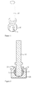
- FIG. 1 is a perspective view illustrating a ball joint unit according to an exemplary embodiment of the present disclosure.
- a ball joint unit is characteristically configured in such a fashion that a ball member (10) and a rod member (12) are integrally formed, and a surface of the ball member (10) is formed with a plurality of lubricant reception recesses (11).
- the ball member (10) is provided with an approximately spherical ball member receptor, and a distal end of the ball member is flatly formed.
- Each of the lubricant recesses (11) on the surface of the ball member (10) is provided with a recess shape with a different depth based on position. That is, as illustrated in FIG.2 , a floor surface of the lubricant recess (11) is flatly provided relative to a central axis of the rod member (12), a depth of each lubricant recess (11) to a longitudinal direction of the ball member (10) is differently formed, while a depth of each lubricant recess (11) to a latitudinal direction of the ball member (10) is identically formed.
- the lubricant recess (11) may be chamfered by a connection portion of the surface of the ball member, whereby amount of lubricant accommodated into the lubricant recess (11) can be maximized, and the accommodated lubricant can be easily transferred to the surface of the ball member (10).
- the lubricant accommodated inside the lubricant recess (11) is preferably a semi-solid lubricant such as grease.
- a liquid or solid lubricant may be used, but the liquid lubricant can be easily leaked out and is not suitable for a long time of use, and it is difficult to use the solid lubricant as the solid lubricant is difficult to be poured into the recess.
- the ball joint unit thus configured is rotatably coupled to a retainer (20) as shown in FIGS. 2 and 3 .
- the retainer (20) is to accommodate the ball member (10), and corresponds in shape to the ball member.
- the retainer (20) is formed with a space coated with lubricant (L).
- the retainer (20) the retainer is configured in such a manner that a ball member support portion (21) wrapping an upper end of the ball member is protruded to a rod member direction, so that the lubricant (L) poured into the retainer (20) can be prevented from leaking.
- the ball member support portion (21) is formed with a diameter smaller than that of the ball member (10) and greater than that of the rod member (12).
- a distal end of the ball member (10) inserted into an interior of the retainer (20) is preferably flat.
- a distal end of the ball member (10) is flatly formed, a distal end of the ball member (10) which is a distal end of the ball joint unit is prevented from being contacted with an inner circumferential surface of a ball member receptor.
- the lubricant (L) can be additionally accommodated in a space formed between the distal end and the inner circumferential surface of a ball member receptor. The space, along with the lubricant recess (11), can perform an operation of additional supply of the lubricant.
- the ball joint unit according to the present disclosure.
- the ball member (10) constituting the ball joint unit is superficially formed with a plurality of recesses like those on a golf ball, where the plurality of recesses accommodates semi-solid lubricant therein, thereby maximally maintaining performance of the ball joint unit for a long time without any frequent re-filling of the lubricant.
- the lubricant coated on the surface of the ball member (10) is fully supplied among the interior of the lubricant recesses (11), the distal end of the ball member (10) and the inner circumferential surface of the a ball member receptor, when the ball joint unit is assembled.
- an inner lateral surface of the retainer (20) coupled by the ball member (10) is also coated with the lubricant (L).
- material of retainer (20) may be provided with rubber or the like if the retainer is not positioned at a place not applied with a heavy load. If the retainer (20) is formed with rubber, it may be easy to insertedly couple the ball member (10). However, in a case the ball member (10) is excessively twisted, initially poured lubricant may be leaked and prematurely depleted, under which the retainer (20) rather softer than the ball member (10) may be excessively worn out.
- the structure is applied that is formed with a plurality of lubricant recesses provided on the surface according to the present disclosure, and even if the lubricant (L) poured into the retainer (20) is leaked, the lubricant (L) accommodated inside the lubricant recesses (11) seeps out little by little onto the surface of the ball member (10) to supplement the insufficient lubricant.
- an area surface-contacted by the inner circumferential surface of the ball member receptor at the retainer (20) and the ball member (10) is substantially reduced to subsequently reduce a surface area on which the lubricant acts, whereby the ball joint unit can be used for a long time without any re-filling of the lubricant.
- the surface that is surface-contacted is also reduced to advantageously decrease the frictional force.
- an upper end of the ball member (10) is wrapped by the ball member support portion (21) to prevent the lubricant (L) accommodated inside the lubricant recesses (11) and the retainer (20) from leaking out to an outside of the retainer (20).
- the ball joint unit according to the present disclosure has an industrial applicability in that the ball member constituting the ball joint unit is superficially formed with a plurality of recesses like those on a golf ball, where the plurality of recesses accommodates lubricant therein, thereby maximally maintaining performance of the ball joint unit for a long time without any frequent re-filling of the lubricant.
Landscapes
- Engineering & Computer Science (AREA)
- General Engineering & Computer Science (AREA)
- Mechanical Engineering (AREA)
- Pivots And Pivotal Connections (AREA)
Abstract
Description
- This application claims the benefit of earlier filing date and right of priority to Korean Patent Application No.
10-2011-0064008, filed on June 29, 2011 - Exemplary embodiments of the present disclosure may relate to a ball joint unit.
- A ball joint unit is connection means for connecting two mutually different elements and enabling a relative movement between the connected mutually different elements.
- Generally, the ball joint unit is configured in such a manner that a distal end of a rod member connected to a first element is formed with a ball member, and a second element connected to the first element is provided with a retainer, where the ball member is insertedly coupled to a spherical space provided inside the retainer.
- Meantime, the ball member of the ball joint inserted into the inner space of the retainer is generally coated with a lubricant such as grease to reduce wear, where if the ball member is repeatedly moved, the grease coated on the surface is exposed to the outside to gradually lose the lubricant performance.
- Particularly, if the ball joint is installed at a position difficult to continuously pour the lubricant, the ball member and/or the retainer are disadvantageously worn by friction between the ball member and the retainer performing real time rotation and twist, to destruct the ball joint unit.
- Therefore, the present disclosure is directed to address one or more of the above disadvantages/problems and to provide a ball joint unit configured to enhance lubricant receptivity.
- Technical subjects to be solved by the present disclosure are not restricted to the above-mentioned description, and any other technical problems not mentioned so far will be clearly appreciated from the following description by the skilled in the art. That is, the present disclosure will be understood more easily and other objects, characteristics, details and advantages thereof will become more apparent in the course of the following explanatory description, which is given, without intending to imply any limitation of the disclosure, with reference to the attached drawings.
- In one general broad aspect of the present disclosure, there is provided a ball joint unit, the unit comprising: a ball member; a plurality of lubricant reception recesses formed on a surface of the ball member, each having a predetermined depth; a rod member connected to a first element to be integrally formed with the ball member; and a retainer connected to a second element and formed with a spherical ball member receptor corresponding in shape to the ball member, wherein the lubricant is accommodated and coated in an interior of the lubricant recesses and a surface of the ball member.
- Preferably, each lubricant reception recess is flat at a floor surface, and the floor surface is formed in parallel with an axial direction of the rod member.
- Preferably, the lubricant reception recess is chamfered by a connection portion of the surface of the ball member.
- Preferably, the lubricant is a semi-solid lubricant like grease.
- Preferably, the ball member is flatly-formed at a distal end to avoid contacting an inner circumferential surface of the ball member receptor.
- Preferably, the retainer is configured in such a manner that a ball member support portion wrapping an upper end of the ball member is protruded to a rod member direction.
- Preferably, the ball member support portion is formed with a diameter smaller than that of the ball member and greater than that of the rod member.
- Preferably, the retainer is formed with a rubber material.
- The ball joint unit according to exemplary embodiments of the present disclosure has an advantageous effect in that the ball member constituting the ball joint unit is superficially formed with a plurality of recesses like those on a golf ball, where the plurality of recesses accommodates lubricant therein, thereby maximally maintaining performance of the ball joint unit for a long time without any frequent re-filling of the lubricant.
- Accompanying drawings are included to provide a further understanding of arrangements and embodiments of the present disclosure and are incorporated in and constitute a part of this application. Now, non-limiting and non-exhaustive exemplary embodiments of the disclosure are described with reference to the following drawings, in which:
-
FIG. 1 is a perspective view illustrating a ball joint unit according to an exemplary embodiment of the present disclosure; and -
FIGS. 2 and3 are schematic views illustrating a ball joint coupled to a retainer ofFIG. 1 according to the present disclosure. - Additional advantages, objects, and features of the disclosure will be set forth in part in the description which follows and in part will become apparent to those having ordinary skill in the art upon examination of the following or may be learned from practice of the disclosure. The objectives and other advantages of the disclosure may be realized and attained by the method particularly pointed out in the written description and claims hereof as well as the appended drawings.
- Hereinafter, exemplary embodiments of the present disclosure are described in detail with reference to the accompanying drawings. It will be appreciated that for simplicity and/or clarity of illustration, elements illustrated in the figure have not necessarily been drawn to scale. For example, the dimensions of some of the elements may be exaggerated relative to other elements for clarity. Further, if considered appropriate, reference numerals have been repeated among the figures to indicate corresponding and/or analogous elements.
- In describing the present disclosure, detailed descriptions of constructions or processes known in the art may be omitted to avoid obscuring appreciation of the invention by a person of ordinary skill in the art with unnecessary detail regarding such known constructions and functions.
- Accordingly, particular terms may be defined to describe the disclosure in the best mode as known by the inventors. Accordingly, the meaning of specific terms or words used in the specification and the claims should not be limited to the literal or commonly employed sense, but should be construed in accordance with the spirit and scope of the disclosure. The definitions of these terms therefore may be determined based on the contents throughout the specification.
- In the following detailed description, numerous specific details are set forth to provide a thorough understanding of claimed subject matter. However, it will be understood by those skilled in the art that claimed subject matter may be practiced without these specific details. In other instances, well-known methods, procedures, components and/or circuits have not been described in detail.
- In the following description and/or claims, the terms "comprise" and "include," along with their derivatives, may be used and are intended as synonyms for each other. Furthermore, the terms "including", "includes", "having", "has", "with", or variants thereof are used in the detailed description and/or the claims to denote non-exhaustive inclusion in a manner similar to the term "comprising".
- Words such as "thereafter," "then," "next," etc. are not intended to limit the order of the processes; these words are simply used to guide the reader through the description of the methods. The terms "first," "second," and the like, herein do not denote any order, quantity, or importance, but rather are used to distinguish one element from another, and the terms "a" and "an" herein do not denote a limitation of quantity, but rather denote the presence of at least one of the referenced item.
- In describing the present disclosure, detailed descriptions of constructions or processes known in the art may be omitted to avoid obscuring appreciation of the invention by a person of ordinary skill in the art with unnecessary detail regarding such known constructions and functions.
- Now, a ball joint unit according to exemplary embodiments of the present disclosure will be described in detail with reference to the accompanying drawings.
-
FIG. 1 is a perspective view illustrating a ball joint unit according to an exemplary embodiment of the present disclosure. - Referring to
FIG.1 , a ball joint unit according to the present disclosure is characteristically configured in such a fashion that a ball member (10) and a rod member (12) are integrally formed, and a surface of the ball member (10) is formed with a plurality of lubricant reception recesses (11). - Preferably, the ball member (10) is provided with an approximately spherical ball member receptor, and a distal end of the ball member is flatly formed.
- Each of the lubricant recesses (11) on the surface of the ball member (10) is provided with a recess shape with a different depth based on position. That is, as illustrated in
FIG.2 , a floor surface of the lubricant recess (11) is flatly provided relative to a central axis of the rod member (12), a depth of each lubricant recess (11) to a longitudinal direction of the ball member (10) is differently formed, while a depth of each lubricant recess (11) to a latitudinal direction of the ball member (10) is identically formed. - The lubricant recess (11) may be chamfered by a connection portion of the surface of the ball member, whereby amount of lubricant accommodated into the lubricant recess (11) can be maximized, and the accommodated lubricant can be easily transferred to the surface of the ball member (10).
- Meanwhile, the lubricant accommodated inside the lubricant recess (11) is preferably a semi-solid lubricant such as grease. Although a liquid or solid lubricant may be used, but the liquid lubricant can be easily leaked out and is not suitable for a long time of use, and it is difficult to use the solid lubricant as the solid lubricant is difficult to be poured into the recess.
- The ball joint unit thus configured is rotatably coupled to a retainer (20) as shown in
FIGS. 2 and3 . The retainer (20) is to accommodate the ball member (10), and corresponds in shape to the ball member. The retainer (20) is formed with a space coated with lubricant (L). - The retainer (20) the retainer is configured in such a manner that a ball member support portion (21) wrapping an upper end of the ball member is protruded to a rod member direction, so that the lubricant (L) poured into the retainer (20) can be prevented from leaking. The ball member support portion (21) is formed with a diameter smaller than that of the ball member (10) and greater than that of the rod member (12).
- Meanwhile, a distal end of the ball member (10) inserted into an interior of the retainer (20) is preferably flat. In a case the distal end of the ball member (10) is flatly formed, a distal end of the ball member (10) which is a distal end of the ball joint unit is prevented from being contacted with an inner circumferential surface of a ball member receptor. Thus, as shown in
FIGS. 2 and3 , the lubricant (L) can be additionally accommodated in a space formed between the distal end and the inner circumferential surface of a ball member receptor. The space, along with the lubricant recess (11), can perform an operation of additional supply of the lubricant. - Now, an operation of the ball joint unit according to the present disclosure will be described.
- With continuing reference to
FIGS. 2 and3 , the ball joint unit according to the present disclosure. - In comparison with the conventional ball joint unit, the ball member (10) constituting the ball joint unit is superficially formed with a plurality of recesses like those on a golf ball, where the plurality of recesses accommodates semi-solid lubricant therein, thereby maximally maintaining performance of the ball joint unit for a long time without any frequent re-filling of the lubricant.
- That is, the lubricant coated on the surface of the ball member (10) is fully supplied among the interior of the lubricant recesses (11), the distal end of the ball member (10) and the inner circumferential surface of the a ball member receptor, when the ball joint unit is assembled.
- At the same time, an inner lateral surface of the retainer (20) coupled by the ball member (10) is also coated with the lubricant (L).
- Meanwhile, material of retainer (20) may be provided with rubber or the like if the retainer is not positioned at a place not applied with a heavy load. If the retainer (20) is formed with rubber, it may be easy to insertedly couple the ball member (10). However, in a case the ball member (10) is excessively twisted, initially poured lubricant may be leaked and prematurely depleted, under which the retainer (20) rather softer than the ball member (10) may be excessively worn out.
- Meanwhile, if the structure is applied that is formed with a plurality of lubricant recesses provided on the surface according to the present disclosure, and even if the lubricant (L) poured into the retainer (20) is leaked, the lubricant (L) accommodated inside the lubricant recesses (11) seeps out little by little onto the surface of the ball member (10) to supplement the insufficient lubricant.
- Furthermore, if a plurality of lubricant recesses is formed on the surface of the ball member (10), an area surface-contacted by the inner circumferential surface of the ball member receptor at the retainer (20) and the ball member (10) is substantially reduced to subsequently reduce a surface area on which the lubricant acts, whereby the ball joint unit can be used for a long time without any re-filling of the lubricant. At the same time, the surface that is surface-contacted is also reduced to advantageously decrease the frictional force.
- Still furthermore, an upper end of the ball member (10) is wrapped by the ball member support portion (21) to prevent the lubricant (L) accommodated inside the lubricant recesses (11) and the retainer (20) from leaking out to an outside of the retainer (20).
- As apparent from the foregoing, the ball joint unit according to the present disclosure has an industrial applicability in that the ball member constituting the ball joint unit is superficially formed with a plurality of recesses like those on a golf ball, where the plurality of recesses accommodates lubricant therein, thereby maximally maintaining performance of the ball joint unit for a long time without any frequent re-filling of the lubricant.
- The previous description of the present disclosure is provided to enable any person skilled in the art to make or use the invention. Various modifications to the disclosure will be readily apparent to those skilled in the art, and the generic principles defined herein may be applied to other variations without departing from the spirit or scope of the disclosure. Thus, the instant disclosure is not intended to limit the examples described herein, but is to be accorded the widest scope consistent with the principles and novel features disclosed herein.
Claims (14)
- A ball joint unit, the unit comprising:a ball member;a plurality of lubricant reception recesses formed on a surface of the ball member, each having a predetermined depth;a rod member connected to a first element to be integrally formed with the ball member; anda retainer connected to a second element and formed with a spherical ball member receptor corresponding in shape to the ball member,wherein the lubricant is accommodated and coated in an interior of the lubricant recesses and a surface of the ball member.
- The ball joint unit of claim 1, wherein each lubricant reception recess is flat at a floor surface, and the floor surface is formed in parallel with an axial direction of the rod member.
- The ball joint unit of claim 1, wherein lubricant reception recess is chamfered by a connection portion of the surface of the ball member.
- The ball joint unit of claim 1, wherein the lubricant is a semi-solid lubricant like grease.
- The ball joint unit of claim 1, wherein the ball member is flatly-formed at a distal end to avoid contacting an inner circumferential surface of the ball member receptor.
- The ball joint unit of claim 1, wherein the retainer is configured in such a manner that a ball member support portion wrapping an upper end of the ball member is protruded to a rod member direction.
- The ball joint unit of claim 6, wherein the ball member support portion is formed with a diameter smaller than that of the ball member and greater than that of the rod member.
- The ball joint unit of claim of 1, wherein Preferably, the retainer is formed with a rubber material.
- The ball joint unit of claim of 2, wherein Preferably, the retainer is formed with a rubber material.
- The ball joint unit of claim of 3, wherein Preferably, the retainer is formed with a rubber material.
- The ball joint unit of claim of 4, wherein Preferably, the retainer is formed with a rubber material.
- The ball joint unit of claim of 5, wherein Preferably, the retainer is formed with a rubber material.
- The ball joint unit of claim of 6, wherein Preferably, the retainer is formed with a rubber material.
- The ball joint unit of claim of 7, wherein Preferably, the retainer is formed with a rubber material.
Applications Claiming Priority (1)
| Application Number | Priority Date | Filing Date | Title |
|---|---|---|---|
| KR1020110064008A KR101811451B1 (en) | 2011-06-29 | 2011-06-29 | Ball Joint Unit |
Publications (2)
| Publication Number | Publication Date |
|---|---|
| EP2541082A1 true EP2541082A1 (en) | 2013-01-02 |
| EP2541082B1 EP2541082B1 (en) | 2015-03-25 |
Family
ID=46085419
Family Applications (1)
| Application Number | Title | Priority Date | Filing Date |
|---|---|---|---|
| EP12167513.6A Not-in-force EP2541082B1 (en) | 2011-06-29 | 2012-05-10 | Ball joint unit |
Country Status (5)
| Country | Link |
|---|---|
| US (1) | US9464662B2 (en) |
| EP (1) | EP2541082B1 (en) |
| JP (1) | JP6054632B2 (en) |
| KR (1) | KR101811451B1 (en) |
| CN (1) | CN102889295B (en) |
Families Citing this family (3)
| Publication number | Priority date | Publication date | Assignee | Title |
|---|---|---|---|---|
| US10914370B2 (en) * | 2015-07-06 | 2021-02-09 | Kongsberg Automotive Ab | Gearshift assembly |
| US20230105661A1 (en) * | 2021-10-06 | 2023-04-06 | Daniel A. Delzer | Locking ball and socket joint |
| USD995275S1 (en) | 2021-10-20 | 2023-08-15 | Daniel A. Delzer | Ball joint stud |
Citations (5)
| Publication number | Priority date | Publication date | Assignee | Title |
|---|---|---|---|---|
| DE857715C (en) * | 1949-12-08 | 1952-12-01 | Ehrenreich & Cie A | Ball joint for purposes of all kinds, especially for steering linkages |
| US2971787A (en) * | 1956-10-29 | 1961-02-14 | Gen Motors Corp | Ball joint assembly |
| US6702502B1 (en) * | 1999-08-13 | 2004-03-09 | ZF Lemförder Metallwaren AG | Ball-and-socket joint |
| US20070140784A1 (en) * | 2003-12-25 | 2007-06-21 | Kabushiki Kaisha Somic Ishikawa | Ball joint and bearing seat thereof |
| KR20110064008A (en) | 2009-12-07 | 2011-06-15 | 현대모비스 주식회사 | Vehicle brake booster |
Family Cites Families (20)
| Publication number | Priority date | Publication date | Assignee | Title |
|---|---|---|---|---|
| US1882956A (en) * | 1929-08-22 | 1932-10-18 | Johnson Bronze Co | Bearing |
| DE3218962A1 (en) * | 1982-05-19 | 1983-11-24 | Springfix Befestigungstechnik | BALL PAN FOR A BALL JOINT |
| DE3608782A1 (en) * | 1986-03-15 | 1987-09-24 | Thyssen Industrie | SWIVEL JOINT WITH FLOW CHANNELS |
| JPS62297525A (en) * | 1986-06-16 | 1987-12-24 | Musashi Seimitsu Ind Co Ltd | Ball joint |
| JPS63168318U (en) | 1988-04-04 | 1988-11-02 | ||
| JPH02253008A (en) | 1989-03-24 | 1990-10-11 | Musashi Seimitsu Ind Co Ltd | Ball stud for ball joint and manufacture thereof |
| JP3388973B2 (en) | 1995-12-27 | 2003-03-24 | 三菱重工業株式会社 | Spherical joint |
| US6109816A (en) * | 1996-09-30 | 2000-08-29 | Bridgestone Corporation | Stabilizer link rod, and method of manufacturing same |
| US6250840B1 (en) * | 1998-09-11 | 2001-06-26 | Trw Inc. | Tie rod end |
| US6042294A (en) * | 1998-11-23 | 2000-03-28 | Trw Inc. | Ball joint having rotational and axial movement |
| JP2001146916A (en) | 1999-11-22 | 2001-05-29 | Minebea Co Ltd | Free spherical ball bearings |
| DE10149609A1 (en) * | 2001-10-09 | 2003-04-10 | Zf Lemfoerder Metallwaren Ag | Ball-and-socket joint for use in car suspension or steering systems has raised section, which is part of surface of sphere, in base of socket, restricting degree of swivel of ball |
| FR2831941B1 (en) | 2001-11-08 | 2004-02-27 | Airbus France | DEVICE FOR LUBRICATING A BALL JOINT BEARING |
| DE10328109B4 (en) * | 2003-06-20 | 2005-12-29 | ZF Lemförder Metallwaren AG | ball joint |
| DE20311595U1 (en) * | 2003-07-28 | 2004-01-15 | Trw Fahrwerksysteme Gmbh & Co Kg | Ball joint and component with ball joint |
| CN101432535A (en) * | 2006-03-31 | 2009-05-13 | 阿尔斯通技术有限公司 | Hydrodynamic axial plain bearing and associated operating method |
| JP2008169953A (en) | 2007-01-12 | 2008-07-24 | Toyota Motor Corp | Connected structure |
| DE102007015616B4 (en) * | 2007-03-29 | 2021-10-21 | Zf Friedrichshafen Ag | Connector for the articulated connection of components arranged in the chassis of a vehicle |
| US20110243650A1 (en) * | 2007-11-08 | 2011-10-06 | Linares Medical Devices, Llc | Joint replacement assembly with surface lubricant distribution configuration established between ball and receiver squeaking or acoustic emissions |
| JP2009210027A (en) * | 2008-03-04 | 2009-09-17 | Jtekt Corp | Ball joint |
-
2011
- 2011-06-29 KR KR1020110064008A patent/KR101811451B1/en not_active Expired - Fee Related
-
2012
- 2012-05-10 EP EP12167513.6A patent/EP2541082B1/en not_active Not-in-force
- 2012-05-15 US US13/472,015 patent/US9464662B2/en not_active Expired - Fee Related
- 2012-05-18 JP JP2012114611A patent/JP6054632B2/en not_active Expired - Fee Related
- 2012-06-12 CN CN201210193465.4A patent/CN102889295B/en not_active Expired - Fee Related
Patent Citations (5)
| Publication number | Priority date | Publication date | Assignee | Title |
|---|---|---|---|---|
| DE857715C (en) * | 1949-12-08 | 1952-12-01 | Ehrenreich & Cie A | Ball joint for purposes of all kinds, especially for steering linkages |
| US2971787A (en) * | 1956-10-29 | 1961-02-14 | Gen Motors Corp | Ball joint assembly |
| US6702502B1 (en) * | 1999-08-13 | 2004-03-09 | ZF Lemförder Metallwaren AG | Ball-and-socket joint |
| US20070140784A1 (en) * | 2003-12-25 | 2007-06-21 | Kabushiki Kaisha Somic Ishikawa | Ball joint and bearing seat thereof |
| KR20110064008A (en) | 2009-12-07 | 2011-06-15 | 현대모비스 주식회사 | Vehicle brake booster |
Also Published As
| Publication number | Publication date |
|---|---|
| US20130004233A1 (en) | 2013-01-03 |
| JP2013011343A (en) | 2013-01-17 |
| KR101811451B1 (en) | 2017-12-21 |
| JP6054632B2 (en) | 2016-12-27 |
| CN102889295A (en) | 2013-01-23 |
| CN102889295B (en) | 2017-05-10 |
| US9464662B2 (en) | 2016-10-11 |
| KR20130002819A (en) | 2013-01-08 |
| EP2541082B1 (en) | 2015-03-25 |
Similar Documents
| Publication | Publication Date | Title |
|---|---|---|
| EP2541082B1 (en) | Ball joint unit | |
| EP1701048A1 (en) | Ball joint and bearing seat for the ball joint | |
| US7708466B2 (en) | Lubricated bushing | |
| CN104541074B (en) | ball joint | |
| CA2671104A1 (en) | Drawer slide | |
| CN204249769U (en) | Rear-swing arm lining | |
| CN201934509U (en) | Shaft sleeve | |
| JP2011169449A (en) | Ball joint | |
| TW504549B (en) | Guide sleeve | |
| EP2295824A2 (en) | Ball-joint dust cover | |
| JP2004169820A (en) | Ball joint | |
| JP5355280B2 (en) | Arrangement method of receiving portion and holding portion in ball joint bearing sheet, and ball joint. | |
| US7441637B2 (en) | Hydraulic shock absorber | |
| US9302560B2 (en) | Stabilizer link | |
| CN203685846U (en) | Ball bearing | |
| JP2013011343A5 (en) | ||
| CN207958712U (en) | A kind of presser feet cam drive and embroidery machine | |
| WO2006070631A1 (en) | Ball joint | |
| CN222415704U (en) | Threading universal joint | |
| CN208764166U (en) | High leakproofness retractable vehicle constant speed short handle cylinder outer race | |
| CN100504094C (en) | vehicle strut | |
| CN201129462Y (en) | Oil seal structure | |
| KR20140056111A (en) | Spindle bearing device, textile machine and method for operating a spindle bearing device and use of an o-ring element | |
| JP5310845B2 (en) | Ball joint | |
| CN207621649U (en) | The bearing oiling device of mechanical equipment |
Legal Events
| Date | Code | Title | Description |
|---|---|---|---|
| PUAI | Public reference made under article 153(3) epc to a published international application that has entered the european phase |
Free format text: ORIGINAL CODE: 0009012 |
|
| AK | Designated contracting states |
Kind code of ref document: A1 Designated state(s): AL AT BE BG CH CY CZ DE DK EE ES FI FR GB GR HR HU IE IS IT LI LT LU LV MC MK MT NL NO PL PT RO RS SE SI SK SM TR |
|
| AX | Request for extension of the european patent |
Extension state: BA ME |
|
| 17P | Request for examination filed |
Effective date: 20130702 |
|
| RBV | Designated contracting states (corrected) |
Designated state(s): AL AT BE BG CH CY CZ DE DK EE ES FI FR GB GR HR HU IE IS IT LI LT LU LV MC MK MT NL NO PL PT RO RS SE SI SK SM TR |
|
| GRAP | Despatch of communication of intention to grant a patent |
Free format text: ORIGINAL CODE: EPIDOSNIGR1 |
|
| INTG | Intention to grant announced |
Effective date: 20141023 |
|
| RIN1 | Information on inventor provided before grant (corrected) |
Inventor name: LEE, SUHYOUNG |
|
| GRAS | Grant fee paid |
Free format text: ORIGINAL CODE: EPIDOSNIGR3 |
|
| GRAA | (expected) grant |
Free format text: ORIGINAL CODE: 0009210 |
|
| AK | Designated contracting states |
Kind code of ref document: B1 Designated state(s): AL AT BE BG CH CY CZ DE DK EE ES FI FR GB GR HR HU IE IS IT LI LT LU LV MC MK MT NL NO PL PT RO RS SE SI SK SM TR |
|
| REG | Reference to a national code |
Ref country code: GB Ref legal event code: FG4D |
|
| REG | Reference to a national code |
Ref country code: CH Ref legal event code: EP |
|
| REG | Reference to a national code |
Ref country code: IE Ref legal event code: FG4D |
|
| REG | Reference to a national code |
Ref country code: DE Ref legal event code: R096 Ref document number: 602012006098 Country of ref document: DE Effective date: 20150507 |
|
| REG | Reference to a national code |
Ref country code: AT Ref legal event code: REF Ref document number: 718067 Country of ref document: AT Kind code of ref document: T Effective date: 20150515 |
|
| REG | Reference to a national code |
Ref country code: NL Ref legal event code: T3 |
|
| PG25 | Lapsed in a contracting state [announced via postgrant information from national office to epo] |
Ref country code: HR Free format text: LAPSE BECAUSE OF FAILURE TO SUBMIT A TRANSLATION OF THE DESCRIPTION OR TO PAY THE FEE WITHIN THE PRESCRIBED TIME-LIMIT Effective date: 20150325 Ref country code: SE Free format text: LAPSE BECAUSE OF FAILURE TO SUBMIT A TRANSLATION OF THE DESCRIPTION OR TO PAY THE FEE WITHIN THE PRESCRIBED TIME-LIMIT Effective date: 20150325 Ref country code: FI Free format text: LAPSE BECAUSE OF FAILURE TO SUBMIT A TRANSLATION OF THE DESCRIPTION OR TO PAY THE FEE WITHIN THE PRESCRIBED TIME-LIMIT Effective date: 20150325 Ref country code: LT Free format text: LAPSE BECAUSE OF FAILURE TO SUBMIT A TRANSLATION OF THE DESCRIPTION OR TO PAY THE FEE WITHIN THE PRESCRIBED TIME-LIMIT Effective date: 20150325 |
|
| REG | Reference to a national code |
Ref country code: AT Ref legal event code: MK05 Ref document number: 718067 Country of ref document: AT Kind code of ref document: T Effective date: 20150325 |
|
| REG | Reference to a national code |
Ref country code: LT Ref legal event code: MG4D |
|
| PG25 | Lapsed in a contracting state [announced via postgrant information from national office to epo] |
Ref country code: RS Free format text: LAPSE BECAUSE OF FAILURE TO SUBMIT A TRANSLATION OF THE DESCRIPTION OR TO PAY THE FEE WITHIN THE PRESCRIBED TIME-LIMIT Effective date: 20150325 Ref country code: GR Free format text: LAPSE BECAUSE OF FAILURE TO SUBMIT A TRANSLATION OF THE DESCRIPTION OR TO PAY THE FEE WITHIN THE PRESCRIBED TIME-LIMIT Effective date: 20150626 Ref country code: LV Free format text: LAPSE BECAUSE OF FAILURE TO SUBMIT A TRANSLATION OF THE DESCRIPTION OR TO PAY THE FEE WITHIN THE PRESCRIBED TIME-LIMIT Effective date: 20150325 |
|
| PG25 | Lapsed in a contracting state [announced via postgrant information from national office to epo] |
Ref country code: PT Free format text: LAPSE BECAUSE OF FAILURE TO SUBMIT A TRANSLATION OF THE DESCRIPTION OR TO PAY THE FEE WITHIN THE PRESCRIBED TIME-LIMIT Effective date: 20150727 Ref country code: RO Free format text: LAPSE BECAUSE OF FAILURE TO SUBMIT A TRANSLATION OF THE DESCRIPTION OR TO PAY THE FEE WITHIN THE PRESCRIBED TIME-LIMIT Effective date: 20150325 Ref country code: EE Free format text: LAPSE BECAUSE OF FAILURE TO SUBMIT A TRANSLATION OF THE DESCRIPTION OR TO PAY THE FEE WITHIN THE PRESCRIBED TIME-LIMIT Effective date: 20150325 Ref country code: ES Free format text: LAPSE BECAUSE OF FAILURE TO SUBMIT A TRANSLATION OF THE DESCRIPTION OR TO PAY THE FEE WITHIN THE PRESCRIBED TIME-LIMIT Effective date: 20150325 Ref country code: SK Free format text: LAPSE BECAUSE OF FAILURE TO SUBMIT A TRANSLATION OF THE DESCRIPTION OR TO PAY THE FEE WITHIN THE PRESCRIBED TIME-LIMIT Effective date: 20150325 Ref country code: CZ Free format text: LAPSE BECAUSE OF FAILURE TO SUBMIT A TRANSLATION OF THE DESCRIPTION OR TO PAY THE FEE WITHIN THE PRESCRIBED TIME-LIMIT Effective date: 20150325 |
|
| PG25 | Lapsed in a contracting state [announced via postgrant information from national office to epo] |
Ref country code: PL Free format text: LAPSE BECAUSE OF FAILURE TO SUBMIT A TRANSLATION OF THE DESCRIPTION OR TO PAY THE FEE WITHIN THE PRESCRIBED TIME-LIMIT Effective date: 20150325 Ref country code: IS Free format text: LAPSE BECAUSE OF FAILURE TO SUBMIT A TRANSLATION OF THE DESCRIPTION OR TO PAY THE FEE WITHIN THE PRESCRIBED TIME-LIMIT Effective date: 20150725 Ref country code: AT Free format text: LAPSE BECAUSE OF FAILURE TO SUBMIT A TRANSLATION OF THE DESCRIPTION OR TO PAY THE FEE WITHIN THE PRESCRIBED TIME-LIMIT Effective date: 20150325 |
|
| REG | Reference to a national code |
Ref country code: CH Ref legal event code: PL |
|
| REG | Reference to a national code |
Ref country code: DE Ref legal event code: R097 Ref document number: 602012006098 Country of ref document: DE |
|
| PG25 | Lapsed in a contracting state [announced via postgrant information from national office to epo] |
Ref country code: LU Free format text: LAPSE BECAUSE OF FAILURE TO SUBMIT A TRANSLATION OF THE DESCRIPTION OR TO PAY THE FEE WITHIN THE PRESCRIBED TIME-LIMIT Effective date: 20150510 Ref country code: LI Free format text: LAPSE BECAUSE OF NON-PAYMENT OF DUE FEES Effective date: 20150531 Ref country code: CH Free format text: LAPSE BECAUSE OF NON-PAYMENT OF DUE FEES Effective date: 20150531 Ref country code: IT Free format text: LAPSE BECAUSE OF FAILURE TO SUBMIT A TRANSLATION OF THE DESCRIPTION OR TO PAY THE FEE WITHIN THE PRESCRIBED TIME-LIMIT Effective date: 20150325 Ref country code: DK Free format text: LAPSE BECAUSE OF FAILURE TO SUBMIT A TRANSLATION OF THE DESCRIPTION OR TO PAY THE FEE WITHIN THE PRESCRIBED TIME-LIMIT Effective date: 20150325 Ref country code: MC Free format text: LAPSE BECAUSE OF FAILURE TO SUBMIT A TRANSLATION OF THE DESCRIPTION OR TO PAY THE FEE WITHIN THE PRESCRIBED TIME-LIMIT Effective date: 20150325 |
|
| PLBE | No opposition filed within time limit |
Free format text: ORIGINAL CODE: 0009261 |
|
| STAA | Information on the status of an ep patent application or granted ep patent |
Free format text: STATUS: NO OPPOSITION FILED WITHIN TIME LIMIT |
|
| REG | Reference to a national code |
Ref country code: IE Ref legal event code: MM4A |
|
| REG | Reference to a national code |
Ref country code: FR Ref legal event code: ST Effective date: 20160129 |
|
| 26N | No opposition filed |
Effective date: 20160105 |
|
| PG25 | Lapsed in a contracting state [announced via postgrant information from national office to epo] |
Ref country code: IE Free format text: LAPSE BECAUSE OF NON-PAYMENT OF DUE FEES Effective date: 20150510 |
|
| PG25 | Lapsed in a contracting state [announced via postgrant information from national office to epo] |
Ref country code: SI Free format text: LAPSE BECAUSE OF FAILURE TO SUBMIT A TRANSLATION OF THE DESCRIPTION OR TO PAY THE FEE WITHIN THE PRESCRIBED TIME-LIMIT Effective date: 20150325 Ref country code: FR Free format text: LAPSE BECAUSE OF NON-PAYMENT OF DUE FEES Effective date: 20150601 |
|
| PG25 | Lapsed in a contracting state [announced via postgrant information from national office to epo] |
Ref country code: BE Free format text: LAPSE BECAUSE OF FAILURE TO SUBMIT A TRANSLATION OF THE DESCRIPTION OR TO PAY THE FEE WITHIN THE PRESCRIBED TIME-LIMIT Effective date: 20150325 |
|
| PG25 | Lapsed in a contracting state [announced via postgrant information from national office to epo] |
Ref country code: MT Free format text: LAPSE BECAUSE OF FAILURE TO SUBMIT A TRANSLATION OF THE DESCRIPTION OR TO PAY THE FEE WITHIN THE PRESCRIBED TIME-LIMIT Effective date: 20150325 |
|
| PG25 | Lapsed in a contracting state [announced via postgrant information from national office to epo] |
Ref country code: HU Free format text: LAPSE BECAUSE OF FAILURE TO SUBMIT A TRANSLATION OF THE DESCRIPTION OR TO PAY THE FEE WITHIN THE PRESCRIBED TIME-LIMIT; INVALID AB INITIO Effective date: 20120510 Ref country code: BG Free format text: LAPSE BECAUSE OF FAILURE TO SUBMIT A TRANSLATION OF THE DESCRIPTION OR TO PAY THE FEE WITHIN THE PRESCRIBED TIME-LIMIT Effective date: 20150325 Ref country code: NO Free format text: LAPSE BECAUSE OF FAILURE TO SUBMIT A TRANSLATION OF THE DESCRIPTION OR TO PAY THE FEE WITHIN THE PRESCRIBED TIME-LIMIT Effective date: 20150625 Ref country code: SM Free format text: LAPSE BECAUSE OF FAILURE TO SUBMIT A TRANSLATION OF THE DESCRIPTION OR TO PAY THE FEE WITHIN THE PRESCRIBED TIME-LIMIT Effective date: 20150325 |
|
| PG25 | Lapsed in a contracting state [announced via postgrant information from national office to epo] |
Ref country code: CY Free format text: LAPSE BECAUSE OF FAILURE TO SUBMIT A TRANSLATION OF THE DESCRIPTION OR TO PAY THE FEE WITHIN THE PRESCRIBED TIME-LIMIT Effective date: 20150325 |
|
| PG25 | Lapsed in a contracting state [announced via postgrant information from national office to epo] |
Ref country code: TR Free format text: LAPSE BECAUSE OF FAILURE TO SUBMIT A TRANSLATION OF THE DESCRIPTION OR TO PAY THE FEE WITHIN THE PRESCRIBED TIME-LIMIT Effective date: 20150325 |
|
| PG25 | Lapsed in a contracting state [announced via postgrant information from national office to epo] |
Ref country code: MK Free format text: LAPSE BECAUSE OF FAILURE TO SUBMIT A TRANSLATION OF THE DESCRIPTION OR TO PAY THE FEE WITHIN THE PRESCRIBED TIME-LIMIT Effective date: 20150325 |
|
| PG25 | Lapsed in a contracting state [announced via postgrant information from national office to epo] |
Ref country code: AL Free format text: LAPSE BECAUSE OF FAILURE TO SUBMIT A TRANSLATION OF THE DESCRIPTION OR TO PAY THE FEE WITHIN THE PRESCRIBED TIME-LIMIT Effective date: 20150325 |
|
| PGFP | Annual fee paid to national office [announced via postgrant information from national office to epo] |
Ref country code: NL Payment date: 20230421 Year of fee payment: 12 |
|
| PGFP | Annual fee paid to national office [announced via postgrant information from national office to epo] |
Ref country code: DE Payment date: 20230420 Year of fee payment: 12 |
|
| PGFP | Annual fee paid to national office [announced via postgrant information from national office to epo] |
Ref country code: GB Payment date: 20230420 Year of fee payment: 12 |
|
| REG | Reference to a national code |
Ref country code: DE Ref legal event code: R119 Ref document number: 602012006098 Country of ref document: DE |
|
| REG | Reference to a national code |
Ref country code: NL Ref legal event code: MM Effective date: 20240601 |
|
| GBPC | Gb: european patent ceased through non-payment of renewal fee |
Effective date: 20240510 |
|
| PG25 | Lapsed in a contracting state [announced via postgrant information from national office to epo] |
Ref country code: NL Free format text: LAPSE BECAUSE OF NON-PAYMENT OF DUE FEES Effective date: 20240601 |
|
| PG25 | Lapsed in a contracting state [announced via postgrant information from national office to epo] |
Ref country code: DE Free format text: LAPSE BECAUSE OF NON-PAYMENT OF DUE FEES Effective date: 20241203 |
|
| PG25 | Lapsed in a contracting state [announced via postgrant information from national office to epo] |
Ref country code: GB Free format text: LAPSE BECAUSE OF NON-PAYMENT OF DUE FEES Effective date: 20240510 |