EP2541033A1 - Système de mélange pour moteur à recirculation des gaz d'échappement - Google Patents
Système de mélange pour moteur à recirculation des gaz d'échappement Download PDFInfo
- Publication number
- EP2541033A1 EP2541033A1 EP20120173849 EP12173849A EP2541033A1 EP 2541033 A1 EP2541033 A1 EP 2541033A1 EP 20120173849 EP20120173849 EP 20120173849 EP 12173849 A EP12173849 A EP 12173849A EP 2541033 A1 EP2541033 A1 EP 2541033A1
- Authority
- EP
- European Patent Office
- Prior art keywords
- exhaust gas
- upstream
- elbow
- downstream
- air
- Prior art date
- Legal status (The legal status is an assumption and is not a legal conclusion. Google has not performed a legal analysis and makes no representation as to the accuracy of the status listed.)
- Granted
Links
Images


Classifications
-
- F—MECHANICAL ENGINEERING; LIGHTING; HEATING; WEAPONS; BLASTING
- F02—COMBUSTION ENGINES; HOT-GAS OR COMBUSTION-PRODUCT ENGINE PLANTS
- F02M—SUPPLYING COMBUSTION ENGINES IN GENERAL WITH COMBUSTIBLE MIXTURES OR CONSTITUENTS THEREOF
- F02M35/00—Combustion-air cleaners, air intakes, intake silencers, or induction systems specially adapted for, or arranged on, internal-combustion engines
- F02M35/10—Air intakes; Induction systems
- F02M35/10209—Fluid connections to the air intake system; their arrangement of pipes, valves or the like
- F02M35/10222—Exhaust gas recirculation [EGR]; Positive crankcase ventilation [PCV]; Additional air admission, lubricant or fuel vapour admission
-
- F—MECHANICAL ENGINEERING; LIGHTING; HEATING; WEAPONS; BLASTING
- F02—COMBUSTION ENGINES; HOT-GAS OR COMBUSTION-PRODUCT ENGINE PLANTS
- F02M—SUPPLYING COMBUSTION ENGINES IN GENERAL WITH COMBUSTIBLE MIXTURES OR CONSTITUENTS THEREOF
- F02M26/00—Engine-pertinent apparatus for adding exhaust gases to combustion-air, main fuel or fuel-air mixture, e.g. by exhaust gas recirculation [EGR] systems
- F02M26/13—Arrangement or layout of EGR passages, e.g. in relation to specific engine parts or for incorporation of accessories
- F02M26/17—Arrangement or layout of EGR passages, e.g. in relation to specific engine parts or for incorporation of accessories in relation to the intake system
- F02M26/19—Means for improving the mixing of air and recirculated exhaust gases, e.g. venturis or multiple openings to the intake system
-
- F—MECHANICAL ENGINEERING; LIGHTING; HEATING; WEAPONS; BLASTING
- F02—COMBUSTION ENGINES; HOT-GAS OR COMBUSTION-PRODUCT ENGINE PLANTS
- F02M—SUPPLYING COMBUSTION ENGINES IN GENERAL WITH COMBUSTIBLE MIXTURES OR CONSTITUENTS THEREOF
- F02M26/00—Engine-pertinent apparatus for adding exhaust gases to combustion-air, main fuel or fuel-air mixture, e.g. by exhaust gas recirculation [EGR] systems
- F02M26/02—EGR systems specially adapted for supercharged engines
- F02M26/04—EGR systems specially adapted for supercharged engines with a single turbocharger
- F02M26/05—High pressure loops, i.e. wherein recirculated exhaust gas is taken out from the exhaust system upstream of the turbine and reintroduced into the intake system downstream of the compressor
-
- Y—GENERAL TAGGING OF NEW TECHNOLOGICAL DEVELOPMENTS; GENERAL TAGGING OF CROSS-SECTIONAL TECHNOLOGIES SPANNING OVER SEVERAL SECTIONS OF THE IPC; TECHNICAL SUBJECTS COVERED BY FORMER USPC CROSS-REFERENCE ART COLLECTIONS [XRACs] AND DIGESTS
- Y02—TECHNOLOGIES OR APPLICATIONS FOR MITIGATION OR ADAPTATION AGAINST CLIMATE CHANGE
- Y02T—CLIMATE CHANGE MITIGATION TECHNOLOGIES RELATED TO TRANSPORTATION
- Y02T10/00—Road transport of goods or passengers
- Y02T10/10—Internal combustion engine [ICE] based vehicles
- Y02T10/12—Improving ICE efficiencies
Definitions
- This disclosure relates generally to an internal combustion engine with an exhaust gas recirculation system and, more particularly, to an air exhaust mixer assembly for mixing intake air with exhaust gas.
- An exhaust gas recirculation system may be used to reduce the generation of undesirable pollutant gases during the operation of internal combustion engines.
- Exhaust gas recirculation systems generally recirculate exhaust gas generated during the combustion process into the intake air supply of the internal combustion engine. The exhaust gas introduced into the engine cylinders displaces a volume of the intake air supply that would otherwise be available for oxygen. Reduced oxygen concentrations lower the maximum combustion temperatures within the cylinders and slow the chemical reactions of the combustion process, which decreases the formation of oxides of nitrogen (NO x ).
- the intake air supply is often compressed through a turbocharger and then supplied to an intake manifold.
- Exhaust gas is introduced into the intake air supply between the turbocharger and the intake manifold.
- Structures for mixing the exhaust gas with the intake air supply may take many different forms.
- the flow characteristics of the intake air supply and the exhaust gas affect the degree to which the air and the exhaust gas mix. Consistent mixing of the air and exhaust gas typically results in improved engine performance.
- U.S. Patent No. 7,624,722 discloses a system for recirculating exhaust gas within an internal combustion engine.
- An intake air conduit receives an intake air stream and an exhaust gas stream and blends or mixes the two streams together.
- a volute redirects the exhaust gas stream into the intake air stream to achieve the desired mixing.
- an internal combustion engine having an exhaust gas recirculation system has a plurality of combustion cylinders and an exhaust gas system fluidly connected to the plurality of combustion cylinders.
- a turbocharger may be fluidly connected to the exhaust gas system.
- An intake air system supplies air to the combustion cylinders.
- the intake air system includes an upstream intake section having an upstream elbow and a downstream elbow.
- a downstream intake manifold receives air from the upstream intake section and supplies the air to the combustion cylinders.
- An exhaust gas recirculation system recirculates exhaust gas from the exhaust gas system to the intake air system.
- the exhaust gas recirculation system includes a mixing tube configured to introduce exhaust gas into the upstream intake section at a location upstream of the downstream elbow.
- an air exhaust mixer assembly in another aspect, includes an upstream intake section including an upstream elbow and a downstream elbow.
- the upstream elbow has a first leg and a second leg connected by an upstream bend.
- the downstream elbow has a third leg and a fourth leg connected by a downstream bend.
- the downstream elbow is located downstream from the upstream elbow.
- the second leg of the upstream elbow and the third leg of the downstream elbow are generally linearly aligned.
- a mixing tube is configured to introduce exhaust gas into the upstream intake section at a location upstream of the downstream elbow.
- a method of mixing air and exhaust gas for an internal combustion engine includes flowing exhaust gas into an exhaust gas system. A portion of the exhaust gas is diverted into an exhaust gas recirculation system. Intake air is directed into an intake air conduit. The intake air is redirected along a first curved path generally along a first plan. The intake air is redirected along a second curved path generally along a second plane. The second plane is non-parallel to the first plane. The intake air is infused with the redirected portion of the exhaust gas at a location upstream of the second curved path.
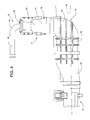
- Fig. 1 depicts an internal combustion engine 10 having a plurality of combustion cylinders 11 configured as a first cylinder bank 12 and a second cylinder bank 13 generally parallel to the first cylinder bank.
- An exhaust gas system 28 includes a first exhaust gas line 20 and a second exhaust gas line 30.
- the first exhaust gas line 20 is fluidly connected to the first cylinder bank 12 and the second exhaust gas line 30 is fluidly connected to the second cylinder bank 13.
- Compressed air is supplied to the first and second cylinder banks 12, 13 by intake air system 50.
- An exhaust gas recirculation system 40 provides for the recirculation of exhaust gas into the intake air system 50 in order to reduce the emissions of the internal combustion engine 10.
- a first cylinder head 14 is secured to the internal combustion engine 10 adjacent the first cylinder bank 12 and a second cylinder head 15 is secured to the internal combustion engine adjacent the second cylinder bank 13 of combustion cylinders.
- the first cylinder bank 12 includes a first cylinder group 16 and a second cylinder group 17.
- the second cylinder bank 13 includes a first cylinder group 18 and a second cylinder group 19.
- first cylinder group 16 of first cylinder bank 12 and the first cylinder group 18 of the second cylinder bank 13 are each depicted with seven combustion cylinders 11 and the second cylinder group 17 of the first cylinder bank 12 and the second cylinder group 19 of the second cylinder bank 13 are each depicted with one combustion cylinder 11, the combustion cylinders of each cylinder bank may be grouped as desired to define or form cylinder groups having different numbers of combustion cylinders.
- First exhaust gas line 20 includes a first exhaust manifold 21 that is fluidly connected to the first cylinder bank 12.
- First exhaust manifold 21 has a first end 22 and an opposite exhaust end 23 with a first section 24 and a second section 25 between the two ends.
- An exhaust restriction valve 26 may be positioned between the first section 24 and the second section 25.
- a first extension pipe 27 extends between the exhaust end 23 of first exhaust manifold 21 and first turbocharger 60 and fluidly connects the first exhaust manifold to the first turbocharger.
- Second exhaust gas line 30 includes a second exhaust manifold 31 that is fluidly connected to the second cylinder bank 13.
- the second exhaust manifold 31 may be generally parallel to the first exhaust manifold and has a first end 32 and an opposite exhaust end 33 with a first section 34 and a second section 35 between the two ends.
- a second extension pipe 37 extends between the exhaust end 33 of the second exhaust manifold 31 and second turbocharger 61 and fluidly connects the second exhaust manifold to the second turbocharger.
- Exhaust gas from the first cylinder group 16 of the first cylinder bank 12 is received within the first section 24 of the first exhaust manifold 21 and, depending upon the positions of exhaust restriction valve 26 and exhaust gas recirculation valve 44, may be routed through the exhaust gas recirculation system 40.
- the exhaust gas recirculation system 40 includes an exhaust gas recirculation duct 41 that may be fluidly connected to the first end 22 of the first exhaust gas line 20 so that exhaust gas from the first cylinder group 16 of the first cylinder bank 12 may be routed or recirculated through the exhaust gas recirculation system and introduced into the intake air system 50.
- Exhaust gas passing through exhaust gas recirculation duct 41 is cooled by one or more cooling components 42.
- the flow rate through exhaust gas recirculation duct 41 may be monitored by a flow meter 43 such as a venturi-style flow meter.
- An exhaust gas recirculation control valve 44 may be provided along exhaust gas recirculation duct 41 to control exhaust gas flow through the exhaust gas recirculation system 40.
- Exhaust gas recirculation control valve 44 together with exhaust restriction valve 26, controls the amount of exhaust gas that is mixed with air that has been compressed by the first turbocharger 60 and the second turbocharger 61 prior to the air entering the first downstream intake manifold 51 and the second downstream intake manifold 52.
- the exhaust gas recirculation duct 41 of the exhaust gas recirculation system 40 may split into two separate legs 45. Each leg 45 fluidly connects to the intake air system 50 between the aftercooler 58 and the first downstream intake manifold 51 and the second downstream intake manifold 52, respectively.
- Intake air system 50 includes a first air intake 53 through which atmospheric air enters the first turbocharger 60, a second air intake 54 through which atmospheric air enters the second turbocharger 61 and a compressed air line 55 through which compressed air is supplied to combustion cylinders 11. More specifically, atmospheric air is compressed by the first and second turbochargers 60, 61 and passes through first compressed air lines 56 to aftercooler 58. Cooled compressed air exits the aftercooler 58 and enters second compressed air lines 57 that are each fluidly connected to an air exhaust mixer assembly indicated schematically at 70 in Fig. 1 . Each air exhaust mixer assembly 70 is fluidly connected to a respective one of the first and second downstream intake manifolds 51, 52.
- Each leg 45 of the exhaust gas recirculation system 40 intersects with and fluidly connects to a respective one of the air exhaust mixer assemblies 70.
- Each air exhaust mixer assembly 70 mixes compressed air from the aftercooler 58 with exhaust gas from the exhaust gas recirculation system 40 and the air exhaust gas mixture is subsequently supplied to a respective one of the first downstream intake manifold 51 and the second downstream intake manifold 52.
- the internal combustion engine 10 depicted in Fig. 1 includes two cylinder banks, the air exhaust mixer assembly 70 disclosed herein may also be used with internal combustion engines having only a single, in-line bank of combustion cylinders.
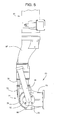
- each air exhaust mixer assembly 70 includes an upstream intake section 71 that forms a part of the air supply system 50.
- Upstream intake section 71 has an upstream elbow 72 and a downstream elbow 76 positioned downstream of the upstream elbow.
- Upstream elbow 72 has an upstream or first leg 73, and a downstream or second leg 74 connected by an upstream bend 75.
- Downstream elbow 76 has an upstream or third leg 77 and a downstream or fourth leg 78 connected by a downstream bend 79.
- Each of the first leg 73, second leg 74, third leg 77, and fourth leg 78 are generally linear.
- Each of the upstream bend 75 and the downstream bend 79 are bent at approximately ninety degree angles.
- the upstream elbow 72 and downstream elbow 76 may have bends of other angles.
- the upstream or first leg 73 of upstream elbow 72 is fluidly connected to aftercooler 58. If desired, the path or intake air conduit between the first leg 73 and the aftercooler 58 may be linear to minimize the pressure drop along the conduit between the first leg and the aftercooler.
- the downstream or second leg 74 of the upstream elbow 72 is fluidly connected and generally aligned with the upstream or third leg 77 of the downstream elbow 76.
- the upstream or first leg 73 and the downstream or second leg 74 of upstream elbow 72 are generally perpendicular to the downstream or fourth leg 78 of downstream elbow 76.
- An exhaust gas recirculation elbow 90 may be located at the end of leg 45 of exhaust gas recirculation system 40 and has a generally linear mixing tube 91 fluidly connected and extending downwardly therefrom.
- Exhaust gas recirculation elbow 90 includes a flange 92 for securing the elbow to a port 80 of the upstream intake section 71.
- port 80 is positioned so that mixing tube 91 is upstream of downstream elbow 76 and extends into upstream elbow 72 at the upstream bend 75. This configuration introduces exhaust gas into the upstream intake section 71 at the upstream elbow.
- Mixing tube 91 may be generally parallel to the downstream or second leg 74 of upstream elbow 72 (and generally perpendicular to the upstream or first 73 of the upstream elbow) which results in a relatively efficient use of space and a relatively compact structure. Although depicted as introducing exhaust gas into the upstream elbow 72, the mixing tube may be placed further upstream.
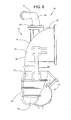
- Air passing through an elbow generally produces two rotating regions of air flow that rotate in generally opposite directions.
- air passing through the upstream elbow 72 has a first region of rotation 82 (depicted as rotating in a counterclockwise direction) and a second region of rotation 83 (also depicted as rotating in a clockwise direction).
- first region of rotation 82 depictted as rotating in a counterclockwise direction
- second region of rotation 83 also depicted as rotating in a clockwise direction.
- the air flow of the first region of rotation 82 and the air flow of the second region of rotation 83 along the vertical centerline 84 move in the same direction.
- the flow of air transitions to a third region of rotation 85 ( Fig.
- the upstream elbow 72 and the downstream elbow 76 are depicted with approximately ninety degree bends, it is believed that satisfactory mixing may still occur if the bends are at angles other than approximately ninety degrees. That is, either or both of the upstream elbow 72 and the downstream elbow 76 may be replaced by a pair of elbows (not shown) that each have a forty-five degree bend or three elbows (not shown) that each have a sixty degree bend. In some configurations, ducts and the intake manifolds may be utilized such that the total angle of all of the elbows does not equal one hundred and eighty degrees. In addition, although the upstream elbow 72 is rotated approximately ninety degrees relative to the downstream elbow 76, it is believed that satisfactory mixing may still occur at angles other than approximately ninety degrees.
- the first downstream intake manifold 51 and the second downstream intake manifold 52 may each be a generally elongated member formed of a plurality of intake manifold elements 95 arranged in a linear array along a longitudinal axis 96.
- the downstream or fourth leg 78 of the downstream elbow 76 of each upstream intake section 71 may be generally parallel to the longitudinal axis 96 of a respective one of the first downstream intake manifold 51 and the second downstream intake manifold 52 and is fluidly connected to its respective downstream intake manifold by a generally linear path or conduit section 97.
- a portion of exhaust gas from the first cylinder group 16 of the first cylinder bank 12 may, at times be, routed through the exhaust gas recirculation system 40 rather than through the first exhaust gas line 20.
- a duct or exhaust gas balance tube 65 is fluidly connected between the first exhaust gas line 20 and the second exhaust gas line 30 to balance or equalize, to a controllable extent, the amount of exhaust gas passing through the first and second turbochargers 60, 61.
- the exhaust gas balance tube 65 provides a path for exhaust gas to travel from second exhaust gas line 30 towards first exhaust gas line 20 to balance the flow through the first and second turbochargers 60, 61.
- turbocharger exhaust gas lines 62 are fluidly connected to an exhaust aftertreament system 63 such as a diesel particulate filter so that the exhaust gas may be filtered prior to being discharged or released to the atmosphere through exhaust gas outlet 64.
- an exhaust aftertreament system 63 such as a diesel particulate filter
- the present disclosure is applicable to internal combustion engines 10 that utilize an exhaust gas recirculation system 40.
- the internal combustion engine 10 includes a plurality of combustion cylinders 11 and an exhaust gas system 28 fluidly connected to the combustion cylinders.
- a turbocharger 60 may be fluidly connected to the exhaust gas system 28.
- An intake air system 50 for supplying air to the combustion cylinders 11 is provided.
- the intake air system 50 includes an upstream intake section 71 having an upstream elbow 72 and a downstream elbow 76.
- a downstream intake manifold 51 receives air from the upstream intake section 71 and supplies the air to the combustion cylinders 11.
- An exhaust gas recirculation system 40 is provided for recirculating exhaust gas from the exhaust gas system to the intake air system.
- the exhaust gas recirculation system 40 includes a mixing tube 91 configured to introduce exhaust gas into the upstream intake section 71 at a location upstream of the downstream elbow 76.
- the upstream intake section 71 and mixing tube 91 define an air exhaust mixer assembly 70 that includes an upstream elbow 72 with a first leg 73 and a second leg 74 connected by an upstream bend 75.
- a downstream elbow 76 has a third leg 77 and a fourth leg 78 connected by a downstream bend 79.
- the downstream elbow 76 is located downstream from the upstream elbow 72.
- the second leg 73 of the upstream elbow 72 and the third leg 77 of the downstream elbow 76 may be generally linearly aligned.
- the mixing tube 91 is configured to introduce exhaust gas into the upstream intake section 71 and is positioned at a location upstream of the downstream elbow 76.
- exhaust gas exits or flows from the first cylinder bank 12 and enters first exhaust manifold 21.
- the flow of exhaust gas from the first cylinder group 16 towards first turbocharger 60 and through exhaust gas recirculation system 40 is controlled by the position of exhaust restriction valve 26 and by the position of exhaust gas recirculation control valve 44.
- the exhaust gas recirculation control valve 44 may be completely closed.
- the exhaust restriction valve 26 may be completely open such that exhaust gas from the first cylinder bank 12 travels through first exhaust manifold 21 and first extension pipe 27 into first turbocharger 60.
- Exhaust gas from the second cylinder bank 13 travels through the second exhaust manifold 31 and second extension pipe 37 into second turbocharger 61.
- exhaust gas recirculation control valve 44 is utilized to initially control the flow through the exhaust gas recirculation system 40. Once the exhaust gas recirculation control valve 44 is fully open, further increases in the amount of recirculated exhaust gas can be accomplished by gradually closing the exhaust restriction valve 26.
- exhaust gas recirculation system 40 As more exhaust gas is recirculated through exhaust gas recirculation system 40, less exhaust gas from the first cylinder group 16 of first cylinder bank 12 may pass through first exhaust manifold 21 into first turbocharger 60. The reduction in exhaust gas flow within the first cylinder bank may result in a pressure differential between the first exhaust manifold 21 and the second exhaust manifold 31. As a result of greater pressure within second exhaust manifold 31 due to the recirculation of some of the exhaust gas from the first cylinder bank, exhaust gas in the second cylinder bank 13 passes from second exhaust manifold 31 through exhaust gas balance tube 65 into first exhaust manifold 21 to balance the flow through the first and second exhaust manifolds.
- Rotation of the first turbocharger 60 compresses air drawn in through the first air intake 53 and rotation of second turbocharger 61 compresses air drawn in through the second air intake 54.
- the compressed air is routed through first compressed air line 56 and through aftercooler 58.
- compressed intake air flows through an intake conduit and enters air exhaust mixer assembly 70 where it is mixed with exhaust gas flowing through the exhaust gas recirculation system 40.
- Compressed air exiting aftercooler 58 enters the upstream elbow 72 of upstream intake section 71 and moves towards downstream elbow 76.
- the compressed air enters the upstream or first leg 73 of upstream elbow 72 and travels around upstream bend 75 and is thus redirected generally along a first curved path generally along a first plane defined by the upstream elbow.
- the compressed air then enters downstream or second leg 74 of upstream elbow 72.
- Air traveling from aftercooler 58 and entering upstream or first leg 73 is traveling in a somewhat linear pattern and transforms to a first region of rotation 82 and a second region of rotation 83 as it exits upstream elbow 72.
- the end of the mixing tube 91 is positioned generally at the upstream elbow 72 in order to introduce or infuse the exhaust gas into the upstream elbow.
Applications Claiming Priority (1)
| Application Number | Priority Date | Filing Date | Title |
|---|---|---|---|
| US13/170,987 US8915235B2 (en) | 2011-06-28 | 2011-06-28 | Mixing system for engine with exhaust gas recirculation |
Publications (2)
| Publication Number | Publication Date |
|---|---|
| EP2541033A1 true EP2541033A1 (fr) | 2013-01-02 |
| EP2541033B1 EP2541033B1 (fr) | 2015-12-09 |
Family
ID=46331108
Family Applications (1)
| Application Number | Title | Priority Date | Filing Date |
|---|---|---|---|
| EP12173849.6A Active EP2541033B1 (fr) | 2011-06-28 | 2012-06-27 | Système de mélange pour moteur à recirculation des gaz d'échappement |
Country Status (2)
| Country | Link |
|---|---|
| US (1) | US8915235B2 (fr) |
| EP (1) | EP2541033B1 (fr) |
Cited By (1)
| Publication number | Priority date | Publication date | Assignee | Title |
|---|---|---|---|---|
| WO2017153042A1 (fr) * | 2016-03-11 | 2017-09-14 | Mtu Friedrichshafen Gmbh | Dispositif d'alimentation pour l'introduction de gaz d'échappement recyclés |
Families Citing this family (7)
| Publication number | Priority date | Publication date | Assignee | Title |
|---|---|---|---|---|
| US9228539B2 (en) * | 2012-12-18 | 2016-01-05 | Deere & Company | Exhaust gas recirculation mixer |
| US20160169166A1 (en) * | 2014-12-10 | 2016-06-16 | Hyundai Motor Company | Structure of engine system |
| US20160186693A1 (en) * | 2014-12-29 | 2016-06-30 | Electro-Motive Diesel, Inc. | Exhaust Gas Recirculation Mixer |
| CN106423806B (zh) * | 2015-07-27 | 2021-05-28 | 斯凯孚公司 | 制备涂层的方法 |
| KR20180109195A (ko) * | 2017-03-27 | 2018-10-08 | 현대자동차주식회사 | 알루미늄 이지알 쿨러를 구비한 엔진 |
| DE102019111421A1 (de) * | 2019-05-03 | 2020-11-05 | Man Energy Solutions Se | Ladeluftleitung einer Brennkraftmaschine und Brennkraftmaschine |
| JP7287261B2 (ja) * | 2019-12-18 | 2023-06-06 | トヨタ紡織株式会社 | 吸気ダクト |
Citations (4)
| Publication number | Priority date | Publication date | Assignee | Title |
|---|---|---|---|---|
| WO2001083975A1 (fr) * | 2000-05-03 | 2001-11-08 | Cooperstandard Automotive Fluid Systems | Appareil de soupape rge |
| US20020088443A1 (en) * | 2001-01-09 | 2002-07-11 | Marthaler Michael J. | Air-exhaust mixer assembly |
| DE102004025254A1 (de) * | 2004-05-22 | 2005-12-08 | Daimlerchrysler Ag | Brennkraftmaschine mit Abgasrückführung |
| US7624722B2 (en) | 2007-12-31 | 2009-12-01 | Cummins, Inc | Apparatus and system for efficiently recirculating an exhaust gas in a combustion engine |
Family Cites Families (13)
| Publication number | Priority date | Publication date | Assignee | Title |
|---|---|---|---|---|
| DE4017823C2 (de) * | 1990-06-02 | 1995-04-06 | Mtu Friedrichshafen Gmbh | Ansauganlage für eine Brennkraftmaschine zur Verwendung bei ein- oder zweistufiger Aufladung |
| JPH0610776A (ja) * | 1992-06-26 | 1994-01-18 | Honda Motor Co Ltd | 排ガス再循環装置およびその製造法 |
| DE19502717C1 (de) | 1995-01-28 | 1996-05-30 | Mtu Friedrichshafen Gmbh | Aufgeladene, mehrzylindrische Brennkraftmaschine mit Abgasrückführung |
| US5924398A (en) * | 1997-10-06 | 1999-07-20 | Ford Global Technologies, Inc. | Flow improvement vanes in the intake system of an internal combustion engine |
| SE9902966L (sv) * | 1999-08-23 | 2000-11-27 | Motortestct Mtc Ab | Anordning för överföring av avgaser från en överladdad förbränningsmotors avgassamlare till dess inloppsledning |
| DE10341393B3 (de) * | 2003-09-05 | 2004-09-23 | Pierburg Gmbh | Luftansaugkanalsystem für eine Verbrennungskraftmaschine |
| ES2280934T3 (es) | 2004-12-30 | 2007-09-16 | C.R.F. Societa' Consortile Per Azioni | Dispositivo para impartir un movimiento de rotacion al flujo de aire alimentado a un motor de combustion interna turboalimentado. |
| US7698898B2 (en) * | 2007-04-04 | 2010-04-20 | General Electric Company | Mixer for cooling and sealing air system for turbomachinery |
| FR2916250B1 (fr) * | 2007-05-14 | 2010-08-27 | Renault Sas | Raccord d'un turbocompresseur avec un catalyseur d'oxydation d'une ligne d'echappement d'un moteur a combustion interne |
| US7740008B2 (en) * | 2007-10-23 | 2010-06-22 | International Engine Intellectual Property Company, Llc | Multiple height fluid mixer and method of use |
| US7730878B2 (en) * | 2007-12-26 | 2010-06-08 | Toyota Motor Engineering & Manufacturing North America, Inc. | Exhaust gas recirculation devices |
| US8096289B2 (en) | 2008-11-18 | 2012-01-17 | Cummins Intellectual Properties, Inc. | Apparatus and method for separating air compressor supply port from the EGR gas |
| US20110192383A1 (en) * | 2010-02-08 | 2011-08-11 | International Engine Intellectual Property Company Llc | Intake air/egr mixing system configuration |
-
2011
- 2011-06-28 US US13/170,987 patent/US8915235B2/en active Active
-
2012
- 2012-06-27 EP EP12173849.6A patent/EP2541033B1/fr active Active
Patent Citations (4)
| Publication number | Priority date | Publication date | Assignee | Title |
|---|---|---|---|---|
| WO2001083975A1 (fr) * | 2000-05-03 | 2001-11-08 | Cooperstandard Automotive Fluid Systems | Appareil de soupape rge |
| US20020088443A1 (en) * | 2001-01-09 | 2002-07-11 | Marthaler Michael J. | Air-exhaust mixer assembly |
| DE102004025254A1 (de) * | 2004-05-22 | 2005-12-08 | Daimlerchrysler Ag | Brennkraftmaschine mit Abgasrückführung |
| US7624722B2 (en) | 2007-12-31 | 2009-12-01 | Cummins, Inc | Apparatus and system for efficiently recirculating an exhaust gas in a combustion engine |
Cited By (4)
| Publication number | Priority date | Publication date | Assignee | Title |
|---|---|---|---|---|
| WO2017153042A1 (fr) * | 2016-03-11 | 2017-09-14 | Mtu Friedrichshafen Gmbh | Dispositif d'alimentation pour l'introduction de gaz d'échappement recyclés |
| CN109072785A (zh) * | 2016-03-11 | 2018-12-21 | Mtu腓特烈港有限责任公司 | 用于导入经再循环的废气的输送装置 |
| RU2700845C1 (ru) * | 2016-03-11 | 2019-09-23 | Мту Фридрихсхафен Гмбх | Система подачи для введения рециркулируемого отработанного газа |
| CN109072785B (zh) * | 2016-03-11 | 2021-07-16 | Mtu腓特烈港有限责任公司 | 用于导入经再循环的废气的输送装置 |
Also Published As
| Publication number | Publication date |
|---|---|
| US8915235B2 (en) | 2014-12-23 |
| US20130000617A1 (en) | 2013-01-03 |
| EP2541033B1 (fr) | 2015-12-09 |
Similar Documents
| Publication | Publication Date | Title |
|---|---|---|
| EP2541033B1 (fr) | Système de mélange pour moteur à recirculation des gaz d'échappement | |
| US8122717B2 (en) | Integration of an exhaust air cooler into a turbocharger | |
| US9080536B2 (en) | Systems and methods for exhaust gas recirculation | |
| US6267106B1 (en) | Induction venturi for an exhaust gas recirculation system in an internal combustion engine | |
| CN202300717U (zh) | 用于高增压发动机系统的egr混合器 | |
| KR101787333B1 (ko) | 배기 시스템 및 선택적인 촉매 환원을 위한 방법 | |
| US20070271920A1 (en) | Exhaust gas recirculation mixer | |
| JP5813017B2 (ja) | ターボチャージャ | |
| US8555638B2 (en) | Internal combustion engine with improved exhaust manifold | |
| US7971579B2 (en) | Air-exhaust mixing apparatus | |
| US10036353B2 (en) | Exhaust gas recirculation apparatus and engine system including such exhaust gas recirculation apparatus | |
| JP2009517581A (ja) | ターボチャージ付き内部燃焼エンジンのための排気ガス再循環混合装置 | |
| US6439212B1 (en) | Bypass venturi assembly and elbow with turning vane for an exhaust gas recirculation system | |
| US20110100325A1 (en) | Three-way throttle valve | |
| US6659092B2 (en) | Bypass assembly with annular bypass venturi for an exhaust gas recirculation system | |
| US20120260650A1 (en) | Internal combustion engine with improved efficiency | |
| US6640542B2 (en) | Bypass venturi assembly with single shaft actuator for an exhaust gas recirculation system | |
| DE102008020405A1 (de) | Abgasturbolader für eine Brennkraftmaschine und Brennkraftmaschine | |
| EP2535549A2 (fr) | Butée de soupape pour moteur à recirculation de gaz dýéchappement | |
| WO2020021952A1 (fr) | Dispositif d'admission d'air pour moteur | |
| US9695779B2 (en) | Exhaust gas mixing system | |
| US9228539B2 (en) | Exhaust gas recirculation mixer | |
| US20170122233A1 (en) | Exhaust Gas Recirculation System | |
| US20140238362A1 (en) | Mixing chamber of exhaust gas recirculation system | |
| JP2023023065A (ja) | 内燃機関の吸気装置 |
Legal Events
| Date | Code | Title | Description |
|---|---|---|---|
| PUAI | Public reference made under article 153(3) epc to a published international application that has entered the european phase |
Free format text: ORIGINAL CODE: 0009012 |
|
| AK | Designated contracting states |
Kind code of ref document: A1 Designated state(s): AL AT BE BG CH CY CZ DE DK EE ES FI FR GB GR HR HU IE IS IT LI LT LU LV MC MK MT NL NO PL PT RO RS SE SI SK SM TR |
|
| AX | Request for extension of the european patent |
Extension state: BA ME |
|
| 17P | Request for examination filed |
Effective date: 20130625 |
|
| RBV | Designated contracting states (corrected) |
Designated state(s): AL AT BE BG CH CY CZ DE DK EE ES FI FR GB GR HR HU IE IS IT LI LT LU LV MC MK MT NL NO PL PT RO RS SE SI SK SM TR |
|
| 17Q | First examination report despatched |
Effective date: 20141007 |
|
| GRAP | Despatch of communication of intention to grant a patent |
Free format text: ORIGINAL CODE: EPIDOSNIGR1 |
|
| INTG | Intention to grant announced |
Effective date: 20150617 |
|
| GRAS | Grant fee paid |
Free format text: ORIGINAL CODE: EPIDOSNIGR3 |
|
| GRAA | (expected) grant |
Free format text: ORIGINAL CODE: 0009210 |
|
| AK | Designated contracting states |
Kind code of ref document: B1 Designated state(s): AL AT BE BG CH CY CZ DE DK EE ES FI FR GB GR HR HU IE IS IT LI LT LU LV MC MK MT NL NO PL PT RO RS SE SI SK SM TR |
|
| REG | Reference to a national code |
Ref country code: GB Ref legal event code: FG4D |
|
| REG | Reference to a national code |
Ref country code: AT Ref legal event code: REF Ref document number: 764691 Country of ref document: AT Kind code of ref document: T Effective date: 20151215 Ref country code: CH Ref legal event code: EP |
|
| REG | Reference to a national code |
Ref country code: IE Ref legal event code: FG4D |
|
| REG | Reference to a national code |
Ref country code: DE Ref legal event code: R096 Ref document number: 602012012832 Country of ref document: DE |
|
| REG | Reference to a national code |
Ref country code: LT Ref legal event code: MG4D |
|
| REG | Reference to a national code |
Ref country code: NL Ref legal event code: MP Effective date: 20151209 |
|
| PG25 | Lapsed in a contracting state [announced via postgrant information from national office to epo] |
Ref country code: LT Free format text: LAPSE BECAUSE OF FAILURE TO SUBMIT A TRANSLATION OF THE DESCRIPTION OR TO PAY THE FEE WITHIN THE PRESCRIBED TIME-LIMIT Effective date: 20151209 Ref country code: ES Free format text: LAPSE BECAUSE OF FAILURE TO SUBMIT A TRANSLATION OF THE DESCRIPTION OR TO PAY THE FEE WITHIN THE PRESCRIBED TIME-LIMIT Effective date: 20151209 Ref country code: NO Free format text: LAPSE BECAUSE OF FAILURE TO SUBMIT A TRANSLATION OF THE DESCRIPTION OR TO PAY THE FEE WITHIN THE PRESCRIBED TIME-LIMIT Effective date: 20160309 |
|
| REG | Reference to a national code |
Ref country code: AT Ref legal event code: MK05 Ref document number: 764691 Country of ref document: AT Kind code of ref document: T Effective date: 20151209 |
|
| PG25 | Lapsed in a contracting state [announced via postgrant information from national office to epo] |
Ref country code: LV Free format text: LAPSE BECAUSE OF FAILURE TO SUBMIT A TRANSLATION OF THE DESCRIPTION OR TO PAY THE FEE WITHIN THE PRESCRIBED TIME-LIMIT Effective date: 20151209 Ref country code: SE Free format text: LAPSE BECAUSE OF FAILURE TO SUBMIT A TRANSLATION OF THE DESCRIPTION OR TO PAY THE FEE WITHIN THE PRESCRIBED TIME-LIMIT Effective date: 20151209 Ref country code: NL Free format text: LAPSE BECAUSE OF FAILURE TO SUBMIT A TRANSLATION OF THE DESCRIPTION OR TO PAY THE FEE WITHIN THE PRESCRIBED TIME-LIMIT Effective date: 20151209 Ref country code: RS Free format text: LAPSE BECAUSE OF FAILURE TO SUBMIT A TRANSLATION OF THE DESCRIPTION OR TO PAY THE FEE WITHIN THE PRESCRIBED TIME-LIMIT Effective date: 20151209 Ref country code: FI Free format text: LAPSE BECAUSE OF FAILURE TO SUBMIT A TRANSLATION OF THE DESCRIPTION OR TO PAY THE FEE WITHIN THE PRESCRIBED TIME-LIMIT Effective date: 20151209 Ref country code: GR Free format text: LAPSE BECAUSE OF FAILURE TO SUBMIT A TRANSLATION OF THE DESCRIPTION OR TO PAY THE FEE WITHIN THE PRESCRIBED TIME-LIMIT Effective date: 20160310 |
|
| PG25 | Lapsed in a contracting state [announced via postgrant information from national office to epo] |
Ref country code: IS Free format text: LAPSE BECAUSE OF FAILURE TO SUBMIT A TRANSLATION OF THE DESCRIPTION OR TO PAY THE FEE WITHIN THE PRESCRIBED TIME-LIMIT Effective date: 20151209 |
|
| PG25 | Lapsed in a contracting state [announced via postgrant information from national office to epo] |
Ref country code: IT Free format text: LAPSE BECAUSE OF FAILURE TO SUBMIT A TRANSLATION OF THE DESCRIPTION OR TO PAY THE FEE WITHIN THE PRESCRIBED TIME-LIMIT Effective date: 20151209 Ref country code: CZ Free format text: LAPSE BECAUSE OF FAILURE TO SUBMIT A TRANSLATION OF THE DESCRIPTION OR TO PAY THE FEE WITHIN THE PRESCRIBED TIME-LIMIT Effective date: 20151209 |
|
| PG25 | Lapsed in a contracting state [announced via postgrant information from national office to epo] |
Ref country code: RO Free format text: LAPSE BECAUSE OF FAILURE TO SUBMIT A TRANSLATION OF THE DESCRIPTION OR TO PAY THE FEE WITHIN THE PRESCRIBED TIME-LIMIT Effective date: 20151209 Ref country code: AT Free format text: LAPSE BECAUSE OF FAILURE TO SUBMIT A TRANSLATION OF THE DESCRIPTION OR TO PAY THE FEE WITHIN THE PRESCRIBED TIME-LIMIT Effective date: 20151209 Ref country code: SK Free format text: LAPSE BECAUSE OF FAILURE TO SUBMIT A TRANSLATION OF THE DESCRIPTION OR TO PAY THE FEE WITHIN THE PRESCRIBED TIME-LIMIT Effective date: 20151209 Ref country code: SM Free format text: LAPSE BECAUSE OF FAILURE TO SUBMIT A TRANSLATION OF THE DESCRIPTION OR TO PAY THE FEE WITHIN THE PRESCRIBED TIME-LIMIT Effective date: 20151209 Ref country code: IS Free format text: LAPSE BECAUSE OF FAILURE TO SUBMIT A TRANSLATION OF THE DESCRIPTION OR TO PAY THE FEE WITHIN THE PRESCRIBED TIME-LIMIT Effective date: 20160409 Ref country code: EE Free format text: LAPSE BECAUSE OF FAILURE TO SUBMIT A TRANSLATION OF THE DESCRIPTION OR TO PAY THE FEE WITHIN THE PRESCRIBED TIME-LIMIT Effective date: 20151209 Ref country code: PT Free format text: LAPSE BECAUSE OF FAILURE TO SUBMIT A TRANSLATION OF THE DESCRIPTION OR TO PAY THE FEE WITHIN THE PRESCRIBED TIME-LIMIT Effective date: 20160411 |
|
| REG | Reference to a national code |
Ref country code: DE Ref legal event code: R097 Ref document number: 602012012832 Country of ref document: DE |
|
| PLBE | No opposition filed within time limit |
Free format text: ORIGINAL CODE: 0009261 |
|
| STAA | Information on the status of an ep patent application or granted ep patent |
Free format text: STATUS: NO OPPOSITION FILED WITHIN TIME LIMIT |
|
| PG25 | Lapsed in a contracting state [announced via postgrant information from national office to epo] |
Ref country code: DK Free format text: LAPSE BECAUSE OF FAILURE TO SUBMIT A TRANSLATION OF THE DESCRIPTION OR TO PAY THE FEE WITHIN THE PRESCRIBED TIME-LIMIT Effective date: 20151209 Ref country code: PL Free format text: LAPSE BECAUSE OF FAILURE TO SUBMIT A TRANSLATION OF THE DESCRIPTION OR TO PAY THE FEE WITHIN THE PRESCRIBED TIME-LIMIT Effective date: 20151209 |
|
| 26N | No opposition filed |
Effective date: 20160912 |
|
| PG25 | Lapsed in a contracting state [announced via postgrant information from national office to epo] |
Ref country code: SI Free format text: LAPSE BECAUSE OF FAILURE TO SUBMIT A TRANSLATION OF THE DESCRIPTION OR TO PAY THE FEE WITHIN THE PRESCRIBED TIME-LIMIT Effective date: 20151209 |
|
| PG25 | Lapsed in a contracting state [announced via postgrant information from national office to epo] |
Ref country code: BE Free format text: LAPSE BECAUSE OF FAILURE TO SUBMIT A TRANSLATION OF THE DESCRIPTION OR TO PAY THE FEE WITHIN THE PRESCRIBED TIME-LIMIT Effective date: 20151209 |
|
| PG25 | Lapsed in a contracting state [announced via postgrant information from national office to epo] |
Ref country code: MC Free format text: LAPSE BECAUSE OF FAILURE TO SUBMIT A TRANSLATION OF THE DESCRIPTION OR TO PAY THE FEE WITHIN THE PRESCRIBED TIME-LIMIT Effective date: 20151209 |
|
| REG | Reference to a national code |
Ref country code: CH Ref legal event code: PL |
|
| REG | Reference to a national code |
Ref country code: IE Ref legal event code: MM4A |
|
| REG | Reference to a national code |
Ref country code: FR Ref legal event code: ST Effective date: 20170228 |
|
| PG25 | Lapsed in a contracting state [announced via postgrant information from national office to epo] |
Ref country code: LI Free format text: LAPSE BECAUSE OF NON-PAYMENT OF DUE FEES Effective date: 20160630 Ref country code: CH Free format text: LAPSE BECAUSE OF NON-PAYMENT OF DUE FEES Effective date: 20160630 Ref country code: FR Free format text: LAPSE BECAUSE OF NON-PAYMENT OF DUE FEES Effective date: 20160630 |
|
| PG25 | Lapsed in a contracting state [announced via postgrant information from national office to epo] |
Ref country code: IE Free format text: LAPSE BECAUSE OF NON-PAYMENT OF DUE FEES Effective date: 20160627 |
|
| PG25 | Lapsed in a contracting state [announced via postgrant information from national office to epo] |
Ref country code: CY Free format text: LAPSE BECAUSE OF FAILURE TO SUBMIT A TRANSLATION OF THE DESCRIPTION OR TO PAY THE FEE WITHIN THE PRESCRIBED TIME-LIMIT Effective date: 20151209 Ref country code: HU Free format text: LAPSE BECAUSE OF FAILURE TO SUBMIT A TRANSLATION OF THE DESCRIPTION OR TO PAY THE FEE WITHIN THE PRESCRIBED TIME-LIMIT; INVALID AB INITIO Effective date: 20120627 |
|
| PG25 | Lapsed in a contracting state [announced via postgrant information from national office to epo] |
Ref country code: HR Free format text: LAPSE BECAUSE OF FAILURE TO SUBMIT A TRANSLATION OF THE DESCRIPTION OR TO PAY THE FEE WITHIN THE PRESCRIBED TIME-LIMIT Effective date: 20151209 Ref country code: MK Free format text: LAPSE BECAUSE OF FAILURE TO SUBMIT A TRANSLATION OF THE DESCRIPTION OR TO PAY THE FEE WITHIN THE PRESCRIBED TIME-LIMIT Effective date: 20151209 Ref country code: TR Free format text: LAPSE BECAUSE OF FAILURE TO SUBMIT A TRANSLATION OF THE DESCRIPTION OR TO PAY THE FEE WITHIN THE PRESCRIBED TIME-LIMIT Effective date: 20151209 Ref country code: MT Free format text: LAPSE BECAUSE OF NON-PAYMENT OF DUE FEES Effective date: 20160630 Ref country code: LU Free format text: LAPSE BECAUSE OF NON-PAYMENT OF DUE FEES Effective date: 20160627 |
|
| PG25 | Lapsed in a contracting state [announced via postgrant information from national office to epo] |
Ref country code: BG Free format text: LAPSE BECAUSE OF FAILURE TO SUBMIT A TRANSLATION OF THE DESCRIPTION OR TO PAY THE FEE WITHIN THE PRESCRIBED TIME-LIMIT Effective date: 20151209 |
|
| PG25 | Lapsed in a contracting state [announced via postgrant information from national office to epo] |
Ref country code: AL Free format text: LAPSE BECAUSE OF FAILURE TO SUBMIT A TRANSLATION OF THE DESCRIPTION OR TO PAY THE FEE WITHIN THE PRESCRIBED TIME-LIMIT Effective date: 20151209 |
|
| P01 | Opt-out of the competence of the unified patent court (upc) registered |
Effective date: 20230517 |
|
| PGFP | Annual fee paid to national office [announced via postgrant information from national office to epo] |
Ref country code: DE Payment date: 20230523 Year of fee payment: 12 |
|
| PGFP | Annual fee paid to national office [announced via postgrant information from national office to epo] |
Ref country code: GB Payment date: 20230523 Year of fee payment: 12 |