EP2541025A2 - Control apparatus for a vehicle - Google Patents
Control apparatus for a vehicle Download PDFInfo
- Publication number
- EP2541025A2 EP2541025A2 EP12159756A EP12159756A EP2541025A2 EP 2541025 A2 EP2541025 A2 EP 2541025A2 EP 12159756 A EP12159756 A EP 12159756A EP 12159756 A EP12159756 A EP 12159756A EP 2541025 A2 EP2541025 A2 EP 2541025A2
- Authority
- EP
- European Patent Office
- Prior art keywords
- vehicle
- fuel
- engine
- road surface
- reduction
- Prior art date
- Legal status (The legal status is an assumption and is not a legal conclusion. Google has not performed a legal analysis and makes no representation as to the accuracy of the status listed.)
- Granted
Links
Images


Classifications
-
- F—MECHANICAL ENGINEERING; LIGHTING; HEATING; WEAPONS; BLASTING
- F02—COMBUSTION ENGINES; HOT-GAS OR COMBUSTION-PRODUCT ENGINE PLANTS
- F02D—CONTROLLING COMBUSTION ENGINES
- F02D33/00—Controlling delivery of fuel or combustion-air, not otherwise provided for
- F02D33/003—Controlling the feeding of liquid fuel from storage containers to carburettors or fuel-injection apparatus ; Failure or leakage prevention; Diagnosis or detection of failure; Arrangement of sensors in the fuel system; Electric wiring; Electrostatic discharge
- F02D33/006—Controlling the feeding of liquid fuel from storage containers to carburettors or fuel-injection apparatus ; Failure or leakage prevention; Diagnosis or detection of failure; Arrangement of sensors in the fuel system; Electric wiring; Electrostatic discharge depending on engine operating conditions, e.g. start, stop or ambient conditions
-
- F—MECHANICAL ENGINEERING; LIGHTING; HEATING; WEAPONS; BLASTING
- F02—COMBUSTION ENGINES; HOT-GAS OR COMBUSTION-PRODUCT ENGINE PLANTS
- F02D—CONTROLLING COMBUSTION ENGINES
- F02D17/00—Controlling engines by cutting out individual cylinders; Rendering engines inoperative or idling
- F02D17/04—Controlling engines by cutting out individual cylinders; Rendering engines inoperative or idling rendering engines inoperative or idling, e.g. caused by abnormal conditions
-
- F—MECHANICAL ENGINEERING; LIGHTING; HEATING; WEAPONS; BLASTING
- F02—COMBUSTION ENGINES; HOT-GAS OR COMBUSTION-PRODUCT ENGINE PLANTS
- F02D—CONTROLLING COMBUSTION ENGINES
- F02D41/00—Electrical control of supply of combustible mixture or its constituents
- F02D41/02—Circuit arrangements for generating control signals
- F02D41/021—Introducing corrections for particular conditions exterior to the engine
-
- F—MECHANICAL ENGINEERING; LIGHTING; HEATING; WEAPONS; BLASTING
- F02—COMBUSTION ENGINES; HOT-GAS OR COMBUSTION-PRODUCT ENGINE PLANTS
- F02N—STARTING OF COMBUSTION ENGINES; STARTING AIDS FOR SUCH ENGINES, NOT OTHERWISE PROVIDED FOR
- F02N11/00—Starting of engines by means of electric motors
- F02N11/08—Circuits specially adapted for starting of engines
- F02N11/0814—Circuits specially adapted for starting of engines comprising means for controlling automatic idle-start-stop
- F02N11/0818—Conditions for starting or stopping the engine or for deactivating the idle-start-stop mode
- F02N11/0833—Vehicle conditions
- F02N11/0837—Environmental conditions thereof, e.g. traffic, weather or road conditions
-
- F—MECHANICAL ENGINEERING; LIGHTING; HEATING; WEAPONS; BLASTING
- F02—COMBUSTION ENGINES; HOT-GAS OR COMBUSTION-PRODUCT ENGINE PLANTS
- F02D—CONTROLLING COMBUSTION ENGINES
- F02D2200/00—Input parameters for engine control
- F02D2200/50—Input parameters for engine control said parameters being related to the vehicle or its components
- F02D2200/501—Vehicle speed
-
- F—MECHANICAL ENGINEERING; LIGHTING; HEATING; WEAPONS; BLASTING
- F02—COMBUSTION ENGINES; HOT-GAS OR COMBUSTION-PRODUCT ENGINE PLANTS
- F02D—CONTROLLING COMBUSTION ENGINES
- F02D2200/00—Input parameters for engine control
- F02D2200/70—Input parameters for engine control said parameters being related to the vehicle exterior
- F02D2200/702—Road conditions
-
- F—MECHANICAL ENGINEERING; LIGHTING; HEATING; WEAPONS; BLASTING
- F02—COMBUSTION ENGINES; HOT-GAS OR COMBUSTION-PRODUCT ENGINE PLANTS
- F02N—STARTING OF COMBUSTION ENGINES; STARTING AIDS FOR SUCH ENGINES, NOT OTHERWISE PROVIDED FOR
- F02N11/00—Starting of engines by means of electric motors
- F02N11/08—Circuits specially adapted for starting of engines
- F02N11/0814—Circuits specially adapted for starting of engines comprising means for controlling automatic idle-start-stop
- F02N11/0818—Conditions for starting or stopping the engine or for deactivating the idle-start-stop mode
- F02N11/0833—Vehicle conditions
- F02N11/084—State of vehicle accessories, e.g. air condition or power steering
-
- F—MECHANICAL ENGINEERING; LIGHTING; HEATING; WEAPONS; BLASTING
- F02—COMBUSTION ENGINES; HOT-GAS OR COMBUSTION-PRODUCT ENGINE PLANTS
- F02N—STARTING OF COMBUSTION ENGINES; STARTING AIDS FOR SUCH ENGINES, NOT OTHERWISE PROVIDED FOR
- F02N2200/00—Parameters used for control of starting apparatus
- F02N2200/02—Parameters used for control of starting apparatus said parameters being related to the engine
- F02N2200/023—Engine temperature
-
- F—MECHANICAL ENGINEERING; LIGHTING; HEATING; WEAPONS; BLASTING
- F02—COMBUSTION ENGINES; HOT-GAS OR COMBUSTION-PRODUCT ENGINE PLANTS
- F02N—STARTING OF COMBUSTION ENGINES; STARTING AIDS FOR SUCH ENGINES, NOT OTHERWISE PROVIDED FOR
- F02N2200/00—Parameters used for control of starting apparatus
- F02N2200/06—Parameters used for control of starting apparatus said parameters being related to the power supply or driving circuits for the starter
- F02N2200/061—Battery state of charge [SOC]
-
- F—MECHANICAL ENGINEERING; LIGHTING; HEATING; WEAPONS; BLASTING
- F02—COMBUSTION ENGINES; HOT-GAS OR COMBUSTION-PRODUCT ENGINE PLANTS
- F02N—STARTING OF COMBUSTION ENGINES; STARTING AIDS FOR SUCH ENGINES, NOT OTHERWISE PROVIDED FOR
- F02N2200/00—Parameters used for control of starting apparatus
- F02N2200/08—Parameters used for control of starting apparatus said parameters being related to the vehicle or its components
- F02N2200/0801—Vehicle speed
-
- F—MECHANICAL ENGINEERING; LIGHTING; HEATING; WEAPONS; BLASTING
- F02—COMBUSTION ENGINES; HOT-GAS OR COMBUSTION-PRODUCT ENGINE PLANTS
- F02N—STARTING OF COMBUSTION ENGINES; STARTING AIDS FOR SUCH ENGINES, NOT OTHERWISE PROVIDED FOR
- F02N2200/00—Parameters used for control of starting apparatus
- F02N2200/08—Parameters used for control of starting apparatus said parameters being related to the vehicle or its components
- F02N2200/0806—Air condition state
-
- F—MECHANICAL ENGINEERING; LIGHTING; HEATING; WEAPONS; BLASTING
- F02—COMBUSTION ENGINES; HOT-GAS OR COMBUSTION-PRODUCT ENGINE PLANTS
- F02N—STARTING OF COMBUSTION ENGINES; STARTING AIDS FOR SUCH ENGINES, NOT OTHERWISE PROVIDED FOR
- F02N2200/00—Parameters used for control of starting apparatus
- F02N2200/08—Parameters used for control of starting apparatus said parameters being related to the vehicle or its components
- F02N2200/0807—Brake booster state
-
- F—MECHANICAL ENGINEERING; LIGHTING; HEATING; WEAPONS; BLASTING
- F02—COMBUSTION ENGINES; HOT-GAS OR COMBUSTION-PRODUCT ENGINE PLANTS
- F02N—STARTING OF COMBUSTION ENGINES; STARTING AIDS FOR SUCH ENGINES, NOT OTHERWISE PROVIDED FOR
- F02N2200/00—Parameters used for control of starting apparatus
- F02N2200/10—Parameters used for control of starting apparatus said parameters being related to driver demands or status
- F02N2200/101—Accelerator pedal position
-
- F—MECHANICAL ENGINEERING; LIGHTING; HEATING; WEAPONS; BLASTING
- F02—COMBUSTION ENGINES; HOT-GAS OR COMBUSTION-PRODUCT ENGINE PLANTS
- F02N—STARTING OF COMBUSTION ENGINES; STARTING AIDS FOR SUCH ENGINES, NOT OTHERWISE PROVIDED FOR
- F02N2200/00—Parameters used for control of starting apparatus
- F02N2200/12—Parameters used for control of starting apparatus said parameters being related to the vehicle exterior
- F02N2200/124—Information about road conditions, e.g. road inclination or surface
-
- Y—GENERAL TAGGING OF NEW TECHNOLOGICAL DEVELOPMENTS; GENERAL TAGGING OF CROSS-SECTIONAL TECHNOLOGIES SPANNING OVER SEVERAL SECTIONS OF THE IPC; TECHNICAL SUBJECTS COVERED BY FORMER USPC CROSS-REFERENCE ART COLLECTIONS [XRACs] AND DIGESTS
- Y02—TECHNOLOGIES OR APPLICATIONS FOR MITIGATION OR ADAPTATION AGAINST CLIMATE CHANGE
- Y02T—CLIMATE CHANGE MITIGATION TECHNOLOGIES RELATED TO TRANSPORTATION
- Y02T10/00—Road transport of goods or passengers
- Y02T10/10—Internal combustion engine [ICE] based vehicles
- Y02T10/40—Engine management systems
Definitions
- the present invention relates to control technology for vehicles equipped with a device that reduces the amount of fuel consumed by an internal combustion engine.
- the idling stop control device automatically stops the idling of the internal combustion engine when a predetermined shutdown condition is satisfied, such as in a case where a vehicle comes to a halt at intersections. Thereafter, when a predetermined restart condition is satisfied, the idling stop control device restarts the engine and moves the vehicle.
- An neutral-at-idle control device is also known as a device for improving automobile fuel consumption.
- the neutral-at-idle control device automatically shifts the transmission into neutral when a predetermined neutral control condition is satisfied during the idling operation of the internal combustion engine, to thereby improve the fuel consumption during the idling operation.
- Vehicles equipped with the idling stop control device described in the above publication or with the neutral-at-idle control device are sometimes provided with a braking system in order to prevent the movement of the vehicles even if the internal combustion engine is automatically stopped or if the transmission is shifted into neutral, in a situation where the vehicles come to a halt in a sloping ground whose slope is smaller than the predetermined value.
- the vehicle Even if being provided with the braking system, however, the vehicle may not be satisfactorily braked by the braking system especially when vehicle weight is large as in the case where the vehicle is being towed. In such a case, the vehicle possibly makes an unanticipated movement when the driver releases a service brake after stopping the vehicle in a sloping ground.
- the invention provides a control apparatus having fuel-reduction controlling device for reducing consumed fuel of an internal combustion engine of a vehicle when predetermined conditions are satisfied, which include at least a condition that the vehicle is at rest; a road surface gradient detector for detecting the slope of the ground surface on which the vehicle is stopped; a standing time measuring unit for measuring the time that elapses after the vehicle is stopped; and fuel-reduction regulating device for regulating the consumed fuel reduction performed by the fuel-reduction controlling device, wherein the fuel-reduction regulating device regulates the consumed fuel reduction performed by the fuel-reduction controlling device if the road surface gradient detector determines that the vehicle is on a slope way, and if the stop time measured by the standing time measuring unit is more than predetermined time.
- the consumed fuel reduction made by the fuel-reduction controlling device is regulated by the fuel-reduction regulating device. This prevents an unanticipated movement of the vehicle, attributable to fuel reduction.
- the fuel-reduction regulating device regulates the consumed fuel reduction made by the fuel-reduction controlling device, regardless of the stop time.
- the consumed fuel reduction made by the fuel-reduction controlling device is regulated by the fuel-reduction regulating device. The vehicle is thus prevented without fail from making the unanticipated movement.
- the predetermined time is determined on the basis of the road surface gradient detected by the road surface gradient detector.
- the consumed fuel reduction made by the fuel-reduction regulating device is regulated with higher accuracy according to the road surface gradient.
- the predetermined time is designed to decrease along with increase in the road surface gradient detected by the road surface gradient detector.
- the predetermined time is designed to decrease along with increase in the road surface gradient. It is then possible to more reliably prevent the unanticipated movement of the vehicle.
- the fuel-reduction controlling device is an idling stop control device that automatically shuts off the internal combustion engine of the vehicle when predetermined shutdown conditions are satisfied, which include at least a condition that the vehicle is at rest.
- the fuel-reduction controlling device is the idling stop control device that automatically shuts off the internal combustion engine of the vehicle when the predetermined shutdown conditions are satisfied, the consumed fuel is more reliably reduced.
- FIG. 1 is a configuration view of a control apparatus 1 for a vehicle according to the embodiment of the invention.
- a vehicle equipped with the control apparatus 1 of the invention has a well-known idling stop control device and a well-known neutral-at-idle control device as fuel-consumption reduction controlling device.
- the idling stop control device automatically stops the operation of an engine 11 (internal combustion engine) when predetermined idling stop conditions (shutdown conditions) are satisfied, such as in a case where the vehicle comes to a halt at intersections (idling stop control). Thereafter, when a predetermined restart condition is satisfied, the idling stop control device automatically restarts the engine 11 and moves the vehicle.
- the idling stop conditions include not only basic start conditions, such as that vehicle speed is zero, and that a brake (service brake of the vehicle) is on, but also the state of operating oil pressure of the brake, engine temperature, battery condition, a demand for activation of an air conditioner, accelerator angle, etc.
- the neutral-at-idle control device automatically shifts a transmission 12 into neutral when predetermined neutral control conditions are satisfied as in a case where the vehicle is stopped at intersections (neutral-at-idle control).
- the neutral control conditions include not only basic start conditions, such as that the vehicle speed is zero, and that the brake is on, but also the state of operating oil pressure of the brake, engine temperature, accelerator angle, etc.
- the idling stop conditions includes more items than the neutral control conditions do, and are therefore more difficult to be satisfied. This is because the idling stop control differs from the neutral-at-idle control in that the engine is stopped, and therefore, the idling stop control needs to be designed so that the vehicle's service brake and the like can operate even when the engine is stopped. On the other hand, the idling stop control is more effective in fuel consumption improvement, as compared to the neutral-at-idle control.
- the vehicle of the embodiment has a vehicle speed sensor 2 that detects the vehicle speed, a gradient detector 3 (road surface gradient detector) that detects an inclination angle ⁇ of the vehicle as road surface gradient, a braking pressure sensor 4 that detects a brake master cylinder hydraulic pressure P of the service brake, a coolant temperature sensor 5 that detects the coolant temperature of the engine, an accelerator angle sensor 6 that detects accelerator angle, and an electronic control unit (hereinafter, referred to as ECU 10) having a controller of the idling stop control device and the neutral-at-idle control device.
- ECU 10 electronice control unit having a controller of the idling stop control device and the neutral-at-idle control device.
- the ECU 10 is formed of an input/output device, a memory device (ROM, RAM, nonvolatile RAM, etc.), a central processing unit (CPU), and the like.
- a memory device ROM, RAM, nonvolatile RAM, etc.
- CPU central processing unit
- the vehicle speed sensor 2, the gradient detector 3, the braking pressure sensor 4, and the coolant temperature sensor 5 are electrically connected to the input side of the ECU 10. Information detected by the above-mentioned sensors is inputted to the ECU 10. Also inputted at the same time is information about the vehicle, which relates to the idling stop conditions and the neural conditions including a deterioration level of a battery of the vehicle, battery charging status, information about operation of an air conditioner's activation switch, etc.
- the engine 11 and the transmission 12 are connected to the output side of the ECU 10 so that the activation of the engine 11 and the transmission 12 may be controlled.
- the ECU 10 is provided with an idling stop controller 20 (idling stop control device) functioning as a controller of the idling stop device, a neutral-at-idle controller 21 functioning as a controller of the neutral-at-idle control device, a timer 22 (vehicle standing time measuring unit), and an idling stop inhibition controller 23 (fuel-reduction regulating device) that inhibits the idling stop control executed by the idling stop controller 20.
- idling stop controller 20 idling stop control device
- a neutral-at-idle controller 21 functioning as a controller of the neutral-at-idle control device
- a timer 22 vehicle standing time measuring unit
- an idling stop inhibition controller 23 fuel-reduction regulating device
- the timer 22 has a function of measuring post-stop elapsed time Ts that is the time that elapses after the vehicle is stopped.
- the ECU 10 controls the execution and cancellation of the idling stop control and the neutral-at-idle control.
- the ECU 10 if the road surface gradient ⁇ is equal to or larger than predetermined slope ⁇ 1, the ECU 10 does not execute the idling stop control and the neutral-at-idle control. Furthermore, when the idling stop conditions are not satisfied before predetermined time elapses after the vehicle is stopped, the ECU 10 does not execute the idling stop control unless the vehicle speed is equal to or higher than predetermined speed V1.
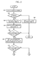
- FIGS. 2 to 4 are flowcharts showing routines of determination between execution and cancellation of the idling stop control and the neutral-at-idle control.
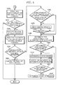
- FIG. 3 shows the routine of determination between execution and cancellation of the idling stop control in the case where the post-stop elapsed time Ts is equal to or less than predetermined time Ta.
- FIG. 4 shows the routine of determination between execution and cancellation of the idling stop control and the neutral-at-idle control in the case where the post-stop elapsed time Ts is more than the predetermined time Ta.
- FIG. 5 is a flowchart showing a subroutine of determination of executability of the automatic stop of the engine.
- FIG. 6 is a flowchart showing a subroutine of a process of judging the necessity of automatic start of the engine.
- FIG. 7 is a flowchart showing a subroutine of determination of executability of neutral-at-idle control.
- FIG. 8 is a flowchart showing a subroutine of a process of judging the necessity of cancellation of neutral-at-idle control.
- the routines are repeatedly carried out when a vehicle power source is turned on.
- Step S10 shown in FIG. 2 vehicle speed is inputted from the vehicle speed sensor 2. The routine then advances to Step S20.
- Step S20 makes a determination as to whether the vehicle is at rest on the basis of the vehicle speed inputted in Step S10.More specifically, it is determined whether the vehicle is at rest on the basis of whether the vehicle speed is zero or equal to or less than a preset value adjacent to zero. If the vehicle is at rest, the routine proceeds to Step S30. If the vehicle is not at rest, the routine moves to Step S80.
- Step S30 the timer 22 measures the post-stop elapsed time Ts that is the time that elapses after the vehicle is stopped. The routine then advances to Step S40.
- Step S40 inputs the road surface gradient ⁇ from the gradient detector 3.
- the road surface gradient ⁇ the inclination angle of the vehicle at the time point when the vehicle is stopped, which is inputted from the gradient detector 3 installed in the vehicle may be inputted.
- the routine then advances to Step S50.
- Step S50 makes a determination as to whether the road surface gradient ⁇ is smaller than the predetermined slope ⁇ 1 inputted in Step S40.
- the predetermined slope ⁇ 1 may be set within a range where the idling stop control and the neutral-at-idle control are able to be executed and also in the vicinity of an upper limit value in the range. If the road surface gradient ⁇ is smaller than the predetermined slope ⁇ 1, the routine moves to Step S60. If the road surface gradient ⁇ is equal to or larger than the predetermined slope ⁇ 1, the routine is ended.
- Step S60 sets predetermined time Ta that is a threshold value for making a determination in Step S80 on the basis of the road surface gradient ⁇ inputted in Step S40.
- the predetermined time Ta may be set so as to be decreased along with increase in the road surface gradient ⁇ .
- the routine then advances to Step S70.
- Step S70 a determination is made as to whether the post-stop elapsed time Ts measured in Step S30 is equal to or less than the predetermined time Ta. If the post-stop elapsed time Ts is equal to or less than the predetermined time Ta, the routine moves to Step S100 in FIG. 3 . If the post-stop elapsed time Ts is more than the predetermined time Ta, the idling stop control is inhibited by the idling stop inhibition controller 23. The routine proceeds to Step S200 in FIG. 4 .
- Step S80 resets the post-stop elapsed time Ts to zero. The routine is then ended.
- Step S100 shown in FIG. 3 carries out the subroutine of determination of executability of the automatic stop of the engine. In this way, it is determined whether the automatic stop of the engine by the idling stop control can be executed. The routine then advances to Step S110.
- Step S110 determines that the automatic stop of the engine can be executed
- the routine proceeds to Step S120. If it is determined that the automatic stop of the engine cannot be executed, the routine is ended.
- Step S120 carries out the automatic stop of the engine by the idling stop control device.
- the routine then advances to Step S130.
- Step S130 carries out the subroutine of a process of judging the necessity of the automatic start of the engine. In this way, it is determined whether the automatic start of the engine after idling stop is necessary. The routine then moves to Step S140.
- Step S140 determines that the automatic start of the engine is necessary, the routine advances to Step S150. If it is determined that the automatic start of the engine is not necessary, the routine returns to Step S120.
- Step S150 carries out the automatic start of the engine. The routine is then ended.
- Step S200 shown in FIG. 4 carries out the subroutine of a process of judging the executability of neutral-at-idle control, which is shown in FIG. 7 , and makes a determination as to whether the neutral-at-idle control can be executed. The routine then moves to Step S210.
- Step S210 determines that the neutral-at-idle control can be executed, the routine proceeds to Step S220. If the neutral-at-idle control cannot be executed, the routine is ended.
- Step S220 carries out the neutral-at-idle control by the neutral-at-idle controller 21. The routine then proceeds to Step S230.
- Step S230 carries out the subroutine of a process of judging the necessity of cancellation of neutral-at-idle control. In this way, it is determined whether the cancellation of the neutral-at-idle control is necessary. The routine then advances to Step S240.
- Step S240 determines that the cancellation of the neutral-at-idle control is necessary, the routine proceeds to Step S250. If it is determined that the cancellation of the neutral-at-idle control is not necessary, the routine proceeds to Step S260.
- Step S250 cancels the neutral-at-idle control. The routine is then ended.
- Step S260 a determination is made as to whether it is determined that the automatic stop of the engine can be executed by the process of determination of executability of the automatic stop of the engine, which is shown by FIG. 5 , before the predetermined time Ta elapses after the vehicle is stopped. If it is never determined that the automatic stop of the engine can be executed before the predetermined time Ta elapses after the vehicle is stopped, the routine moves to Step S270. If it is determined even once that the automatic stop can be executed, the routine proceeds to Step S290.
- Step S270 vehicle speed V is inputted from the vehicle speed sensor 2.
- the routine then advances to Step S280.
- Step S280 makes a determination as to whether the vehicle speed V inputted in Step S270 is equal to or higher than predetermined speed V1. It is considered annoying to the driver if idling stop is executed each time the vehicle runs at a creep speed as in the case where the vehicle is put into a garage. For this reason, the predetermined speed V1 may be set at a speed higher than the creep speed. If the vehicle speed V is equal to or higher than the predetermined speed V1, the routine proceeds to Step S290. If the vehicle speed V is lower than the predetermined speed V1, the routine moves to Step S270.
- the controls executed in Steps S30 to S70 and Steps S260 to S280 correspond to second regulating device of the present invention.
- Step S290 carries out the subroutine of determination of executability of the automatic stop of the engine, which is shown in FIG 5 . In this way, it is determined whether the automatic stop of the engine by the idling stop control can be executed. The routine then advances to Step S300.
- Step S300 determines that the automatic stop of the engine can be executed, the routine proceeds to Step S310. If it is determined that the automatic stop of the engine cannot be executed, the routine is ended.
- Step S310 carries out the automatic stop of the engine by the idling stop controller 20.
- the routine then advances to Step S320.
- Step S320 carries out the subroutine of a process of judging the necessity of the automatic start of the engine, which is shown in FIG. 6 . In this way, it is determined whether the automatic start of the engine after the idling stop control is necessary. The routine then advances to Step S330.
- Step S330 determines that the automatic start of the engine is necessary, the routine moves to Step S340. If it is determined that the automatic start of the engine is not necessary, the routine returns to Step S310.
- Step S340 carries out the automatic start of the engine by the idling stop controller 20. The routine is then ended.
- FIG. 5 is a flowchart showing a subroutine of a process of judging the executability of the automatic stop of the engine.
- Step S400 the process of determination of executability of the automatic stop of the engine firstly makes a determination in Step S400 as to whether the battery is deteriorated. More specifically, it is determined whether the vehicle battery has an internal resistance lower than 10 m ⁇ . If the internal resistance is lower than 10 m ⁇ , it is determined that the battery is not deteriorated. The routine proceeds to Step S410.
- Step S410 makes a determination as to whether the battery is sufficiently charged. More specifically, it is determined whether a charge amount of the vehicle battery is equal to or larger than 80 percent. If the charge amount is equal to or larger than 80 percent, it is determined that the battery is sufficiently charged. The routine then moves to Step S420.
- Step S420 makes a determination as to whether the activation of the air conditioner is demanded. It is determined whether the activation switch of the air conditioner is in an OFF position. If the switch is OFF, it is determined that the activation of the air conditioner is not demanded, and the routine proceeds to Step S430.
- Step S430 makes a determination as to whether the engine 11 is in a warm-up state. It is determined whether the coolant temperature inputted from the coolant temperature sensor 5 is equal to or higher than 60°C. If the temperature is equal to or higher than 60°C, it is determined that the engine 11 is in the warm-up state. The routine then moves to Step S440.
- Step S440 makes a determination as to whether the brake master cylinder of the vehicle service brake has a sufficient hydraulic pressure. It is determined whether the hydraulic pressure P of the brake master cylinder, which is inputted from the braking pressure sensor 4, is equal to or higher than reference braking pressure Ps (0.5 MPa, for example). If the hydraulic pressure P is equal to or higher than the reference braking pressure Ps, it is determined that the hydraulic pressure is sufficient. The routine then advances to Step S450.
- Step S450 makes a determination as to whether the accelerator angle inputted from the accelerator angle sensor 6 is zero. If the accelerator angle is zero, the routine proceeds to Step S460.
- Step S460 determines that the automatic stop of the engine can be executed. The subroutine then returns.
- Step S470 if Step S400 determines that the battery internal resistance is equal to or higher than 10 m ⁇ , if Step S410 determines that the battery charge amount is smaller than 80 percent, if Step S420 determines that the activation switch of the air conditioner is ON, if Step S430 determines that the coolant temperature is lower than 60°C, if Step S440 determines that the hydraulic pressure of the brake mastering cylinder is lower than 0.5 MPa or if Step S450 determines that the accelerator angle is larger than zero.
- Step S470 determines that the automatic stop of the engine cannot be executed. The subroutine then returns.
- FIG. 6 is a flowchart showing the subroutine of the process of judging the necessity of the automatic start of the engine.
- Step S500 the process of judging the necessity of the automatic start of the engine first makes a determination as to whether the battery is sufficiently charged in Step S500. It is determined whether the vehicle battery has a charge amount equal to or larger than 80 percent. If the charge amount is equal to or larger than 80 percent, it is determined that the battery is sufficiently charged. The routine then moves to Step S510.
- Step S510 makes a determination as to whether the activation of the air conditioner is demanded. It is determined whether the activation switch of the air conditioner is in the OFF position. If the switch is OFF, it is determined that the activation of the air conditioner is not demanded, and the routine proceeds to Step S520.
- Step S520 makes a determination as to whether the engine 11 is in the warm-up state. It is determined whether the coolant temperature inputted from the coolant temperature sensor 5 is equal to or higher than 60°C. If the temperature is equal to or higher than 60°C, it is determined that the engine 11 is in the warm-up state. The routine then moves to Step S530.
- Step S530 makes a determination as to whether the brake master cylinder of the vehicle service brake has sufficient hydraulic pressure. It is determined whether the hydraulic pressure P of the brake master cylinder, which is inputted from the braking pressure sensor 4, is equal to or higher than the reference braking pressure Ps (0.5 MPa, for example). If the hydraulic pressure P is equal to or higher than the reference braking pressure Ps, it is determined that the hydraulic pressure is sufficient. The routine then advances to Step S540.
- Step S540 makes a determination as to whether the accelerator angle is zero. If the accelerator angle is zero, the routine proceeds to Step S550.
- Step S550 determines that the automatic start of the engine is not necessary. The subroutine then returns.
- Step S500 determines that the battery charge amount is smaller than 80 percent
- Step S510 determines that the activation switch of the air conditioner is ON
- Step S520 determines that the coolant temperature is lower than 60°C
- Step S530 determines that the hydraulic pressure P of the brake mastering cylinder is lower than the reference braking pressure Ps or if Step S540 determines that the accelerator angle is larger than zero.
- Step S560 determines that the automatic start of the engine is necessary. The subroutine then returns.
- FIG. 7 is a flowchart showing the subroutine of the process of determination of the executability of the neutral-at-idle control.
- the process of determination of executability of the neutral-at-idle control first makes a determination as to whether the engine 11 is in the warm-up state in Step S600. It is determined whether the coolant temperature inputted from the coolant temperature sensor 5 is equal to or higher than 60°C. If the temperature is equal to or higher than 60°C, it is determined that the engine 11 is in the warm-up state. The routine then moves to Step S610.
- Step S610 makes a determination as to whether the brake master cylinder of the service brake has sufficient hydraulic pressure. It is determined whether the hydraulic pressure P of the brake master cylinder, which is inputted from the braking pressure sensor 4, is equal to or higher than reference braking pressure Pn (0.2 MPa, for example). If the hydraulic pressure P is equal to or higher than the reference braking pressure Pn, it is determined that the hydraulic pressure is sufficient. The routine then advances to Step S620.
- Step S620 makes a determination as to whether the accelerator angle inputted from the accelerator angle sensor 6 is zero. If the accelerator angle is zero, the routine proceeds to Step S630.
- Step S630 determines that the neutral-at-idle control can be executed. The subroutine then returns.
- Step S640 The routine advances to Step S640 if Step S600 determines that the coolant temperature of the engine is lower than 60°C, if Step S610 determines that the hydraulic pressure P of the brake mastering cylinder is lower than the reference braking pressure Pn or if Step S620 determines that the accelerator angle is larger than zero.
- Step S640 determines that the neutral-at-idle control can be executed. The subroutine then returns.
- FIG. 8 is a flowchart showing the subroutine of the process of judging the necessity of cancellation of neutral-at-idle control.
- Step S700 the process of judging the necessity of cancellation of neutral-at-idle control first makes a determination as to whether the engine 11 is in the warm-up state in Step S700. It is determined whether the coolant temperature inputted from the coolant temperature sensor 5 is equal to or higher than 60°C. If the temperature is equal to or higher than 60°C, it is determined that the engine 11 is in the warm-up state. The routine then moves to Step S710.
- Step S710 makes a determination as to whether the brake master cylinder of the service brake has sufficient hydraulic pressure. It is determined whether the hydraulic pressure P of the brake master cylinder, which is inputted from the braking pressure sensor 4, is equal to or higher than the reference braking pressure Pn (0.2 MPa, for example). If the hydraulic pressure P is equal to or higher than the reference braking pressure Pn, it is determined that the hydraulic pressure is sufficient. The routine then advances to Step S720.
- Step S720 makes a determination as to whether the accelerator angle inputted from the accelerator angle sensor 6 is zero. If the accelerator angle is zero, the routine proceeds to Step S730.
- Step S730 determines that the cancellation of the neutral-at-idle control is not necessary. The subroutine then returns.
- Step S740 if Step S700 determines that the coolant temperature of the engine is lower than 60°C, if Step S710 determines that the hydraulic pressure P of the brake mastering cylinder is lower than the reference braking pressure Pn or if Step S720 determines that the accelerator angle is larger than zero.
- Step S740 determines that the cancellation of the neutral-at-idle control is necessary. The subroutine then returns.
- the embodiment regulates the idling stop control and the neutral-at-idle control if the road surface gradient ⁇ is equal to or larger than the predetermined slope ⁇ 1 when the vehicle is stopped. Even if the other idling stop conditions and neutral control conditions are satisfied, the automatic stop of the engine 11 and the neutral control are regulated. It is thus possible to prevent an unanticipated movement of the vehicle, namely, downward sliding of the vehicle, which occurs when the idling stop control and the neutral-at-idle control are executed when the vehicle is stopped in a greatly inclined place.
- the idling stop control is disabled until the vehicle V becomes equal to or higher than the predetermined speed V1. If the idling stop conditions are not satisfied before the predetermined time Ta elapses after the vehicle is stopped, there is the possibility that the hydraulic pressure of the brake master cylinder of the vehicle is not sufficient.
- the automatic stop is regulated until the vehicle speed V becomes equal to or higher than the predetermined speed V1, and the vehicle moves and then stops again, that is, until there is the possibility the hydraulic pressure is obtained, it is possible to prevent the driver from releasing the service brake after stopping the vehicle on the sloping ground and thus to reliably prevent the vehicle from making an unanticipated movement. In particular, it is possible to prevent without fail an unanticipated movement of the vehicle, which is likely to occur on the sloping ground such as in the case where the vehicle is being towed or carrying a large load. It is desirable that the control for regulating the idling stop control after the predetermined time Ta elapses from the time point when the vehicle is stopped be executed only if the road surface gradient ⁇ is smaller than the predetermined slope ⁇ 1.
- the road surface gradient ⁇ is used not only when a determination is made as to whether the idling stop control should be regulated but also when the predetermined time Ta is set, which is a time period measured after the vehicle is stopped and in which it is determined whether the idling stop conditions are never satisfied. Consequently, the regulation of the idling stop control is more reliably carried out. If the idling stop conditions are never satisfied within a short elapsed time after the vehicle is stopped, the regulation of the idling stop control is continued. On this account, the regulation of the idling stop control is becoming hard to cancel along with increase in the road surface gradient ⁇ . It is therefore possible to more reliably prevent an unanticipated movement of the vehicle.
- the automatic stop of the engine is regulated until the vehicle speed V becomes equal to or higher than the predetermined speed V1.
- the neutral-at-idle control may be regulated until the vehicle speed V becomes equal to or higher than the predetermined speed V1. In either way, it is possible to reliably prevent an unanticipated movement of the vehicle, which occurs because the neutral-at-idle control is executed on the sloping ground when the vehicle is stopped.
- the routine may be ended when the post-stop elapsed time Ts is more than the predetermined time Ta in Step S70 shown in FIG. 2 .
- the idling stop control is regulated. In result, an unanticipated movement of the vehicle can be prevented when the idling stop control is executed on the sloping ground.
Landscapes
- Engineering & Computer Science (AREA)
- Chemical & Material Sciences (AREA)
- Combustion & Propulsion (AREA)
- Mechanical Engineering (AREA)
- General Engineering & Computer Science (AREA)
- Health & Medical Sciences (AREA)
- Life Sciences & Earth Sciences (AREA)
- Atmospheric Sciences (AREA)
- Environmental & Geological Engineering (AREA)
- Toxicology (AREA)
- Control Of Vehicle Engines Or Engines For Specific Uses (AREA)
- Output Control And Ontrol Of Special Type Engine (AREA)
Abstract
Description
- The present invention relates to control technology for vehicles equipped with a device that reduces the amount of fuel consumed by an internal combustion engine.
- Conventionally known as a device for improving automobile fuel consumption is an idling stop control device that shuts off the internal combustion engine when an automobile comes to a halt at intersections or the like.
- The idling stop control device automatically stops the idling of the internal combustion engine when a predetermined shutdown condition is satisfied, such as in a case where a vehicle comes to a halt at intersections. Thereafter, when a predetermined restart condition is satisfied, the idling stop control device restarts the engine and moves the vehicle.
- Furthermore, there is a technology of regulating the automatic shutdown of the internal combustion engine, which is carried out by the idling stop control device according to the slope of the ground surface in vehicles equipped with the idling stop control device. If the automatic stop of the internal combustion engine is regulated when the road surface gradient is equal to or larger than the predetermined value, it is possible to discourage a reduction in hydraulic pressures supplied to a braking device and a transmission, and prevent an unanticipated movement of the vehicle before the hydraulic pressures are obtained at the time of restart (Unexamined Japanese Patent Publication No.
2005-207327 - An neutral-at-idle control device is also known as a device for improving automobile fuel consumption.
- The neutral-at-idle control device automatically shifts the transmission into neutral when a predetermined neutral control condition is satisfied during the idling operation of the internal combustion engine, to thereby improve the fuel consumption during the idling operation.
- Vehicles equipped with the idling stop control device described in the above publication or with the neutral-at-idle control device are sometimes provided with a braking system in order to prevent the movement of the vehicles even if the internal combustion engine is automatically stopped or if the transmission is shifted into neutral, in a situation where the vehicles come to a halt in a sloping ground whose slope is smaller than the predetermined value.
- Even if being provided with the braking system, however, the vehicle may not be satisfactorily braked by the braking system especially when vehicle weight is large as in the case where the vehicle is being towed. In such a case, the vehicle possibly makes an unanticipated movement when the driver releases a service brake after stopping the vehicle in a sloping ground.
- It is an object of the invention to provide a control apparatus for a vehicle, which is capable of avoiding an unanticipated movement of a vehicle without fail when the vehicle is stopped in a sloping ground.
- This object can be achieved by the features specified in the claims. Particularly, in order to achieve the above object, the invention provides a control apparatus having fuel-reduction controlling device for reducing consumed fuel of an internal combustion engine of a vehicle when predetermined conditions are satisfied, which include at least a condition that the vehicle is at rest; a road surface gradient detector for detecting the slope of the ground surface on which the vehicle is stopped; a standing time measuring unit for measuring the time that elapses after the vehicle is stopped; and fuel-reduction regulating device for regulating the consumed fuel reduction performed by the fuel-reduction controlling device, wherein
the fuel-reduction regulating device regulates the consumed fuel reduction performed by the fuel-reduction controlling device if the road surface gradient detector determines that the vehicle is on a slope way, and if the stop time measured by the standing time measuring unit is more than predetermined time. - This way, if the predetermined conditions are not satisfied when the predetermined time elapses after the vehicle is stopped in a sloping ground whose slope is smaller than the predetermined value, the consumed fuel reduction made by the fuel-reduction controlling device is regulated by the fuel-reduction regulating device. This prevents an unanticipated movement of the vehicle, attributable to fuel reduction.
- Preferably, if the road surface gradient detected by the road surface gradient detector is larger than the predetermined value, the fuel-reduction regulating device regulates the consumed fuel reduction made by the fuel-reduction controlling device, regardless of the stop time.
- By so doing, when the vehicle is stopped in a sloping ground whose slope is larger than the predetermined value, the consumed fuel reduction made by the fuel-reduction controlling device is regulated by the fuel-reduction regulating device. The vehicle is thus prevented without fail from making the unanticipated movement.
- Preferably, the predetermined time is determined on the basis of the road surface gradient detected by the road surface gradient detector.
- Since the predetermined time serving as a threshold value of the time that elapses after the vehicle is stopped is determined on the basis of the road surface gradient detected by the road surface gradient detector, the consumed fuel reduction made by the fuel-reduction regulating device is regulated with higher accuracy according to the road surface gradient.
- Preferably, the predetermined time is designed to decrease along with increase in the road surface gradient detected by the road surface gradient detector.
- This way, the predetermined time is designed to decrease along with increase in the road surface gradient. It is then possible to more reliably prevent the unanticipated movement of the vehicle.
- Preferably, the fuel-reduction controlling device is an idling stop control device that automatically shuts off the internal combustion engine of the vehicle when predetermined shutdown conditions are satisfied, which include at least a condition that the vehicle is at rest.
- Since the fuel-reduction controlling device is the idling stop control device that automatically shuts off the internal combustion engine of the vehicle when the predetermined shutdown conditions are satisfied, the consumed fuel is more reliably reduced.
- The present invention will become more fully understood from the detailed description given hereinafter and the accompanying drawings which are given by way of illustration only, and thus, are not limitative of the present invention, and wherein:
-
FIG. 1 is a schematic configuration view of a control apparatus for a vehicle according to an embodiment of the invention; -
FIG. 2 is a flowchart showing a routine of determination between execution and cancellation of idling stop control and neutral-at-idle control; -
FIG. 3 is a flowchart showing a routine of determination between execution and cancellation of idling stop control and neutral-at-idle control; -
FIG. 4 is a flowchart showing a routine of determination between execution and cancellation of idling stop control and neutral-at-idle control; -
FIG. 5 is a flowchart showing a subroutine of a process of judging the executability of automatic stop of the engine; -
FIG. 6 is a flowchart showing a subroutine of a process of judging the necessity of automatic start of the engine; -
FIG. 7 is a flowchart showing a subroutine of a process of judging the executability of neutral-at-idle control; and -
FIG. 8 is a flowchart showing a subroutine of a process of judging the necessity of cancellation of neutral-at-idle control. - An embodiment of the invention will be described below with reference to the attached drawings.
-
FIG. 1 is a configuration view of acontrol apparatus 1 for a vehicle according to the embodiment of the invention. - A vehicle equipped with the
control apparatus 1 of the invention has a well-known idling stop control device and a well-known neutral-at-idle control device as fuel-consumption reduction controlling device. - The idling stop control device automatically stops the operation of an engine 11 (internal combustion engine) when predetermined idling stop conditions (shutdown conditions) are satisfied, such as in a case where the vehicle comes to a halt at intersections (idling stop control). Thereafter, when a predetermined restart condition is satisfied, the idling stop control device automatically restarts the
engine 11 and moves the vehicle. - The idling stop conditions include not only basic start conditions, such as that vehicle speed is zero, and that a brake (service brake of the vehicle) is on, but also the state of operating oil pressure of the brake, engine temperature, battery condition, a demand for activation of an air conditioner, accelerator angle, etc.
- The neutral-at-idle control device automatically shifts a
transmission 12 into neutral when predetermined neutral control conditions are satisfied as in a case where the vehicle is stopped at intersections (neutral-at-idle control). - The neutral control conditions include not only basic start conditions, such as that the vehicle speed is zero, and that the brake is on, but also the state of operating oil pressure of the brake, engine temperature, accelerator angle, etc.
- The idling stop conditions includes more items than the neutral control conditions do, and are therefore more difficult to be satisfied. This is because the idling stop control differs from the neutral-at-idle control in that the engine is stopped, and therefore, the idling stop control needs to be designed so that the vehicle's service brake and the like can operate even when the engine is stopped. On the other hand, the idling stop control is more effective in fuel consumption improvement, as compared to the neutral-at-idle control.
- As shown in
FIG. 1 , the vehicle of the embodiment has avehicle speed sensor 2 that detects the vehicle speed, a gradient detector 3 (road surface gradient detector) that detects an inclination angle θ of the vehicle as road surface gradient, abraking pressure sensor 4 that detects a brake master cylinder hydraulic pressure P of the service brake, acoolant temperature sensor 5 that detects the coolant temperature of the engine, anaccelerator angle sensor 6 that detects accelerator angle, and an electronic control unit (hereinafter, referred to as ECU 10) having a controller of the idling stop control device and the neutral-at-idle control device. - The
ECU 10 is formed of an input/output device, a memory device (ROM, RAM, nonvolatile RAM, etc.), a central processing unit (CPU), and the like. - The
vehicle speed sensor 2, thegradient detector 3, thebraking pressure sensor 4, and thecoolant temperature sensor 5 are electrically connected to the input side of theECU 10. Information detected by the above-mentioned sensors is inputted to theECU 10. Also inputted at the same time is information about the vehicle, which relates to the idling stop conditions and the neural conditions including a deterioration level of a battery of the vehicle, battery charging status, information about operation of an air conditioner's activation switch, etc. - The
engine 11 and thetransmission 12 are connected to the output side of theECU 10 so that the activation of theengine 11 and thetransmission 12 may be controlled. - The ECU 10 is provided with an idling stop controller 20 (idling stop control device) functioning as a controller of the idling stop device, a neutral-at-
idle controller 21 functioning as a controller of the neutral-at-idle control device, a timer 22 (vehicle standing time measuring unit), and an idling stop inhibition controller 23 (fuel-reduction regulating device) that inhibits the idling stop control executed by theidling stop controller 20. - The
timer 22 has a function of measuring post-stop elapsed time Ts that is the time that elapses after the vehicle is stopped. - Based upon the inputted information, the
ECU 10 controls the execution and cancellation of the idling stop control and the neutral-at-idle control. - According to the present embodiment, if the road surface gradient θ is equal to or larger than predetermined slope θ1, the
ECU 10 does not execute the idling stop control and the neutral-at-idle control. Furthermore, when the idling stop conditions are not satisfied before predetermined time elapses after the vehicle is stopped, theECU 10 does not execute the idling stop control unless the vehicle speed is equal to or higher than predetermined speed V1. -
FIGS. 2 to 4 are flowcharts showing routines of determination between execution and cancellation of the idling stop control and the neutral-at-idle control.FIG. 3 shows the routine of determination between execution and cancellation of the idling stop control in the case where the post-stop elapsed time Ts is equal to or less than predetermined time Ta.FIG. 4 shows the routine of determination between execution and cancellation of the idling stop control and the neutral-at-idle control in the case where the post-stop elapsed time Ts is more than the predetermined time Ta. -
FIG. 5 is a flowchart showing a subroutine of determination of executability of the automatic stop of the engine.FIG. 6 is a flowchart showing a subroutine of a process of judging the necessity of automatic start of the engine.FIG. 7 is a flowchart showing a subroutine of determination of executability of neutral-at-idle control.FIG. 8 is a flowchart showing a subroutine of a process of judging the necessity of cancellation of neutral-at-idle control. - The routines are repeatedly carried out when a vehicle power source is turned on.
- In Step S10 shown in
FIG. 2 , vehicle speed is inputted from thevehicle speed sensor 2. The routine then advances to Step S20. - Step S20 makes a determination as to whether the vehicle is at rest on the basis of the vehicle speed inputted in Step S10.More specifically, it is determined whether the vehicle is at rest on the basis of whether the vehicle speed is zero or equal to or less than a preset value adjacent to zero. If the vehicle is at rest, the routine proceeds to Step S30. If the vehicle is not at rest, the routine moves to Step S80.
- In Step S30, the
timer 22 measures the post-stop elapsed time Ts that is the time that elapses after the vehicle is stopped. The routine then advances to Step S40. - Step S40 inputs the road surface gradient θ from the
gradient detector 3. As the road surface gradient θ, the inclination angle of the vehicle at the time point when the vehicle is stopped, which is inputted from thegradient detector 3 installed in the vehicle may be inputted. The routine then advances to Step S50. - Step S50 makes a determination as to whether the road surface gradient θ is smaller than the predetermined slope θ1 inputted in Step S40. The predetermined slope θ1 may be set within a range where the idling stop control and the neutral-at-idle control are able to be executed and also in the vicinity of an upper limit value in the range. If the road surface gradient θ is smaller than the predetermined slope θ1, the routine moves to Step S60. If the road surface gradient θ is equal to or larger than the predetermined slope θ1, the routine is ended.
- Step S60 sets predetermined time Ta that is a threshold value for making a determination in Step S80 on the basis of the road surface gradient θ inputted in Step S40. The predetermined time Ta may be set so as to be decreased along with increase in the road surface gradient θ. The routine then advances to Step S70.
- In Step S70, a determination is made as to whether the post-stop elapsed time Ts measured in Step S30 is equal to or less than the predetermined time Ta. If the post-stop elapsed time Ts is equal to or less than the predetermined time Ta, the routine moves to Step S100 in
FIG. 3 . If the post-stop elapsed time Ts is more than the predetermined time Ta, the idling stop control is inhibited by the idlingstop inhibition controller 23. The routine proceeds to Step S200 inFIG. 4 . - Step S80 resets the post-stop elapsed time Ts to zero. The routine is then ended.
- Step S100 shown in
FIG. 3 carries out the subroutine of determination of executability of the automatic stop of the engine. In this way, it is determined whether the automatic stop of the engine by the idling stop control can be executed. The routine then advances to Step S110. - If, as a result of the process executed in Step S100, Step S110 determines that the automatic stop of the engine can be executed, the routine proceeds to Step S120. If it is determined that the automatic stop of the engine cannot be executed, the routine is ended.
- Step S120 carries out the automatic stop of the engine by the idling stop control device. The routine then advances to Step S130.
- Step S130 carries out the subroutine of a process of judging the necessity of the automatic start of the engine. In this way, it is determined whether the automatic start of the engine after idling stop is necessary. The routine then moves to Step S140.
- If, as a result of the process executed in Step S130, Step S140 determines that the automatic start of the engine is necessary, the routine advances to Step S150. If it is determined that the automatic start of the engine is not necessary, the routine returns to Step S120.
- Step S150 carries out the automatic start of the engine. The routine is then ended.
- Step S200 shown in
FIG. 4 carries out the subroutine of a process of judging the executability of neutral-at-idle control, which is shown inFIG. 7 , and makes a determination as to whether the neutral-at-idle control can be executed. The routine then moves to Step S210. - If, as a result of the process executed in Step S200, Step S210 determines that the neutral-at-idle control can be executed, the routine proceeds to Step S220. If the neutral-at-idle control cannot be executed, the routine is ended.
- Step S220 carries out the neutral-at-idle control by the neutral-at-
idle controller 21. The routine then proceeds to Step S230. - Step S230 carries out the subroutine of a process of judging the necessity of cancellation of neutral-at-idle control. In this way, it is determined whether the cancellation of the neutral-at-idle control is necessary. The routine then advances to Step S240.
- If, as a result of the process executed in Step S230, Step S240 determines that the cancellation of the neutral-at-idle control is necessary, the routine proceeds to Step S250. If it is determined that the cancellation of the neutral-at-idle control is not necessary, the routine proceeds to Step S260.
- Step S250 cancels the neutral-at-idle control. The routine is then ended.
- In Step S260, a determination is made as to whether it is determined that the automatic stop of the engine can be executed by the process of determination of executability of the automatic stop of the engine, which is shown by
FIG. 5 , before the predetermined time Ta elapses after the vehicle is stopped. If it is never determined that the automatic stop of the engine can be executed before the predetermined time Ta elapses after the vehicle is stopped, the routine moves to Step S270. If it is determined even once that the automatic stop can be executed, the routine proceeds to Step S290. - In Step S270, vehicle speed V is inputted from the
vehicle speed sensor 2. The routine then advances to Step S280. - Step S280 makes a determination as to whether the vehicle speed V inputted in Step S270 is equal to or higher than predetermined speed V1. It is considered annoying to the driver if idling stop is executed each time the vehicle runs at a creep speed as in the case where the vehicle is put into a garage. For this reason, the predetermined speed V1 may be set at a speed higher than the creep speed. If the vehicle speed V is equal to or higher than the predetermined speed V1, the routine proceeds to Step S290. If the vehicle speed V is lower than the predetermined speed V1, the routine moves to Step S270. The controls executed in Steps S30 to S70 and Steps S260 to S280 correspond to second regulating device of the present invention.
- Step S290 carries out the subroutine of determination of executability of the automatic stop of the engine, which is shown in
FIG 5 . In this way, it is determined whether the automatic stop of the engine by the idling stop control can be executed. The routine then advances to Step S300. - If, as a result of the process executed in Step S290, Step S300 determines that the automatic stop of the engine can be executed, the routine proceeds to Step S310. If it is determined that the automatic stop of the engine cannot be executed, the routine is ended.
- Step S310 carries out the automatic stop of the engine by the idling
stop controller 20. The routine then advances to Step S320. - Step S320 carries out the subroutine of a process of judging the necessity of the automatic start of the engine, which is shown in
FIG. 6 . In this way, it is determined whether the automatic start of the engine after the idling stop control is necessary. The routine then advances to Step S330. - If, as a result of the process executed in Step S320, Step S330 determines that the automatic start of the engine is necessary, the routine moves to Step S340. If it is determined that the automatic start of the engine is not necessary, the routine returns to Step S310.
- Step S340 carries out the automatic start of the engine by the idling
stop controller 20. The routine is then ended. -
FIG. 5 is a flowchart showing a subroutine of a process of judging the executability of the automatic stop of the engine. - As shown in
FIG. 5 , the process of determination of executability of the automatic stop of the engine firstly makes a determination in Step S400 as to whether the battery is deteriorated. More specifically, it is determined whether the vehicle battery has an internal resistance lower than 10 mΩ. If the internal resistance is lower than 10 mΩ, it is determined that the battery is not deteriorated. The routine proceeds to Step S410. - Step S410 makes a determination as to whether the battery is sufficiently charged. More specifically, it is determined whether a charge amount of the vehicle battery is equal to or larger than 80 percent. If the charge amount is equal to or larger than 80 percent, it is determined that the battery is sufficiently charged. The routine then moves to Step S420.
- Step S420 makes a determination as to whether the activation of the air conditioner is demanded. It is determined whether the activation switch of the air conditioner is in an OFF position. If the switch is OFF, it is determined that the activation of the air conditioner is not demanded, and the routine proceeds to Step S430.
- Step S430 makes a determination as to whether the
engine 11 is in a warm-up state. It is determined whether the coolant temperature inputted from thecoolant temperature sensor 5 is equal to or higher than 60°C. If the temperature is equal to or higher than 60°C, it is determined that theengine 11 is in the warm-up state. The routine then moves to Step S440. - Step S440 makes a determination as to whether the brake master cylinder of the vehicle service brake has a sufficient hydraulic pressure. It is determined whether the hydraulic pressure P of the brake master cylinder, which is inputted from the
braking pressure sensor 4, is equal to or higher than reference braking pressure Ps (0.5 MPa, for example). If the hydraulic pressure P is equal to or higher than the reference braking pressure Ps, it is determined that the hydraulic pressure is sufficient. The routine then advances to Step S450. - Step S450 makes a determination as to whether the accelerator angle inputted from the
accelerator angle sensor 6 is zero. If the accelerator angle is zero, the routine proceeds to Step S460. - Step S460 determines that the automatic stop of the engine can be executed. The subroutine then returns.
- The routine advances to Step S470 if Step S400 determines that the battery internal resistance is equal to or higher than 10 mΩ, if Step S410 determines that the battery charge amount is smaller than 80 percent, if Step S420 determines that the activation switch of the air conditioner is ON, if Step S430 determines that the coolant temperature is lower than 60°C, if Step S440 determines that the hydraulic pressure of the brake mastering cylinder is lower than 0.5 MPa or if Step S450 determines that the accelerator angle is larger than zero.
- Step S470 determines that the automatic stop of the engine cannot be executed. The subroutine then returns.
-
FIG. 6 is a flowchart showing the subroutine of the process of judging the necessity of the automatic start of the engine. - As shown in
FIG. 6 , the process of judging the necessity of the automatic start of the engine first makes a determination as to whether the battery is sufficiently charged in Step S500. It is determined whether the vehicle battery has a charge amount equal to or larger than 80 percent. If the charge amount is equal to or larger than 80 percent, it is determined that the battery is sufficiently charged. The routine then moves to Step S510. - Step S510 makes a determination as to whether the activation of the air conditioner is demanded. It is determined whether the activation switch of the air conditioner is in the OFF position. If the switch is OFF, it is determined that the activation of the air conditioner is not demanded, and the routine proceeds to Step S520.
- Step S520 makes a determination as to whether the
engine 11 is in the warm-up state. It is determined whether the coolant temperature inputted from thecoolant temperature sensor 5 is equal to or higher than 60°C. If the temperature is equal to or higher than 60°C, it is determined that theengine 11 is in the warm-up state. The routine then moves to Step S530. - Step S530 makes a determination as to whether the brake master cylinder of the vehicle service brake has sufficient hydraulic pressure. It is determined whether the hydraulic pressure P of the brake master cylinder, which is inputted from the
braking pressure sensor 4, is equal to or higher than the reference braking pressure Ps (0.5 MPa, for example). If the hydraulic pressure P is equal to or higher than the reference braking pressure Ps, it is determined that the hydraulic pressure is sufficient. The routine then advances to Step S540. - Step S540 makes a determination as to whether the accelerator angle is zero. If the accelerator angle is zero, the routine proceeds to Step S550.
- Step S550 determines that the automatic start of the engine is not necessary. The subroutine then returns.
- The routine advances to Step S560 if Step S500 determines that the battery charge amount is smaller than 80 percent, if Step S510 determines that the activation switch of the air conditioner is ON, if Step S520 determines that the coolant temperature is lower than 60°C, if Step S530 determines that the hydraulic pressure P of the brake mastering cylinder is lower than the reference braking pressure Ps or if Step S540 determines that the accelerator angle is larger than zero.
- Step S560 determines that the automatic start of the engine is necessary. The subroutine then returns.
-
FIG. 7 is a flowchart showing the subroutine of the process of determination of the executability of the neutral-at-idle control. - As shown in
FIG. 7 , the process of determination of executability of the neutral-at-idle control first makes a determination as to whether theengine 11 is in the warm-up state in Step S600. It is determined whether the coolant temperature inputted from thecoolant temperature sensor 5 is equal to or higher than 60°C. If the temperature is equal to or higher than 60°C, it is determined that theengine 11 is in the warm-up state. The routine then moves to Step S610. - Step S610 makes a determination as to whether the brake master cylinder of the service brake has sufficient hydraulic pressure. It is determined whether the hydraulic pressure P of the brake master cylinder, which is inputted from the
braking pressure sensor 4, is equal to or higher than reference braking pressure Pn (0.2 MPa, for example). If the hydraulic pressure P is equal to or higher than the reference braking pressure Pn, it is determined that the hydraulic pressure is sufficient. The routine then advances to Step S620. - Step S620 makes a determination as to whether the accelerator angle inputted from the
accelerator angle sensor 6 is zero. If the accelerator angle is zero, the routine proceeds to Step S630. - Step S630 determines that the neutral-at-idle control can be executed. The subroutine then returns.
- The routine advances to Step S640 if Step S600 determines that the coolant temperature of the engine is lower than 60°C, if Step S610 determines that the hydraulic pressure P of the brake mastering cylinder is lower than the reference braking pressure Pn or if Step S620 determines that the accelerator angle is larger than zero.
- Step S640 determines that the neutral-at-idle control can be executed. The subroutine then returns.
-
FIG. 8 is a flowchart showing the subroutine of the process of judging the necessity of cancellation of neutral-at-idle control. - As shown in
FIG. 8 , the process of judging the necessity of cancellation of neutral-at-idle control first makes a determination as to whether theengine 11 is in the warm-up state in Step S700. It is determined whether the coolant temperature inputted from thecoolant temperature sensor 5 is equal to or higher than 60°C. If the temperature is equal to or higher than 60°C, it is determined that theengine 11 is in the warm-up state. The routine then moves to Step S710. - Step S710 makes a determination as to whether the brake master cylinder of the service brake has sufficient hydraulic pressure. It is determined whether the hydraulic pressure P of the brake master cylinder, which is inputted from the
braking pressure sensor 4, is equal to or higher than the reference braking pressure Pn (0.2 MPa, for example). If the hydraulic pressure P is equal to or higher than the reference braking pressure Pn, it is determined that the hydraulic pressure is sufficient. The routine then advances to Step S720. - Step S720 makes a determination as to whether the accelerator angle inputted from the
accelerator angle sensor 6 is zero. If the accelerator angle is zero, the routine proceeds to Step S730. - Step S730 determines that the cancellation of the neutral-at-idle control is not necessary. The subroutine then returns.
- The routine advances to Step S740 if Step S700 determines that the coolant temperature of the engine is lower than 60°C, if Step S710 determines that the hydraulic pressure P of the brake mastering cylinder is lower than the reference braking pressure Pn or if Step S720 determines that the accelerator angle is larger than zero.
- Step S740 determines that the cancellation of the neutral-at-idle control is necessary. The subroutine then returns.
- By executing the controls as described above, the embodiment regulates the idling stop control and the neutral-at-idle control if the road surface gradient θ is equal to or larger than the predetermined slope θ1 when the vehicle is stopped. Even if the other idling stop conditions and neutral control conditions are satisfied, the automatic stop of the
engine 11 and the neutral control are regulated. It is thus possible to prevent an unanticipated movement of the vehicle, namely, downward sliding of the vehicle, which occurs when the idling stop control and the neutral-at-idle control are executed when the vehicle is stopped in a greatly inclined place. - According to the embodiment, if the idling stop conditions are not satisfied before the predetermined time Ta elapses after the vehicle is stopped, the idling stop control is disabled until the vehicle V becomes equal to or higher than the predetermined speed V1. If the idling stop conditions are not satisfied before the predetermined time Ta elapses after the vehicle is stopped, there is the possibility that the hydraulic pressure of the brake master cylinder of the vehicle is not sufficient. However, since the automatic stop is regulated until the vehicle speed V becomes equal to or higher than the predetermined speed V1, and the vehicle moves and then stops again, that is, until there is the possibility the hydraulic pressure is obtained, it is possible to prevent the driver from releasing the service brake after stopping the vehicle on the sloping ground and thus to reliably prevent the vehicle from making an unanticipated movement. In particular, it is possible to prevent without fail an unanticipated movement of the vehicle, which is likely to occur on the sloping ground such as in the case where the vehicle is being towed or carrying a large load. It is desirable that the control for regulating the idling stop control after the predetermined time Ta elapses from the time point when the vehicle is stopped be executed only if the road surface gradient θ is smaller than the predetermined slope θ1.
- The road surface gradient θ is used not only when a determination is made as to whether the idling stop control should be regulated but also when the predetermined time Ta is set, which is a time period measured after the vehicle is stopped and in which it is determined whether the idling stop conditions are never satisfied. Consequently, the regulation of the idling stop control is more reliably carried out. If the idling stop conditions are never satisfied within a short elapsed time after the vehicle is stopped, the regulation of the idling stop control is continued. On this account, the regulation of the idling stop control is becoming hard to cancel along with increase in the road surface gradient θ. It is therefore possible to more reliably prevent an unanticipated movement of the vehicle.
- According to the embodiment, if the idling stop conditions are not satisfied before the predetermined time Ta elapses after the vehicle is stopped, the automatic stop of the engine is regulated until the vehicle speed V becomes equal to or higher than the predetermined speed V1. However, if the neutral control conditions are not satisfied before the predetermined time Ta elapses after the vehicle is stopped, the neutral-at-idle control may be regulated until the vehicle speed V becomes equal to or higher than the predetermined speed V1. In either way, it is possible to reliably prevent an unanticipated movement of the vehicle, which occurs because the neutral-at-idle control is executed on the sloping ground when the vehicle is stopped.
- Moreover, if the vehicle is equipped with the idling stop control device only, the routine may be ended when the post-stop elapsed time Ts is more than the predetermined time Ta in Step S70 shown in
FIG. 2 . This way, if the idling stop conditions are not satisfied before the predetermined time Ta elapses after the vehicle is stopped, the idling stop control is regulated. In result, an unanticipated movement of the vehicle can be prevented when the idling stop control is executed on the sloping ground.
Claims (5)
- A control apparatus for a vehicle, comprising:fuel-reduction controlling device (20) for reducing consumed fuel of an internal combustion engine (11) of a vehicle when predetermined conditions are satisfied, which include at least a condition that the vehicle is at rest;a road surface gradient detector (3) for detecting the slope of the ground surface on which the vehicle is stopped;a standing time measuring unit (22) for measuring the time that elapses after the vehicle is stopped; anda fuel-reduction regulating device (23) for regulating the consumed fuel reduction performed by the fuel-reduction controlling device (20), characterized in that:the fuel-reduction regulating device (23) regulates the consumed fuel reduction performed by the fuel-reduction controlling device (20) if the road surface gradient detector (3) determines that the vehicle is on a slope way, and if the stop time measured by the standing time measuring unit (22) is more than predetermined time.
- The control apparatus for a vehicle according to claim 1, characterized in that:if the road surface gradient detected by the road surface gradient detector is larger than the predetermined value, the fuel-reduction regulating device regulates the consumed fuel reduction made by the fuel-reduction controlling device, regardless of the stop time.
- The control apparatus for a vehicle according to either one of claims 1 and 2, characterized in that:the predetermined time is determined on the basis of the road surface gradient detected by the road surface gradient detector.
- The control apparatus for a vehicle according to claim 3, characterized in that:the predetermined time is designed to decrease along with increase in the road surface gradient detected by the road surface gradient detector.
- The control apparatus for a vehicle according to any one of claims 1 to 4, characterized in that:the fuel-reduction controlling device is idling stop control device that automatically shuts off the internal combustion engine of the vehicle when predetermined shutdown conditions are satisfied, which include at least a condition that the vehicle is at rest.
Applications Claiming Priority (1)
| Application Number | Priority Date | Filing Date | Title |
|---|---|---|---|
| JP2011129067A JP5585787B2 (en) | 2011-06-09 | 2011-06-09 | Vehicle control device |
Publications (3)
| Publication Number | Publication Date |
|---|---|
| EP2541025A2 true EP2541025A2 (en) | 2013-01-02 |
| EP2541025A3 EP2541025A3 (en) | 2014-06-04 |
| EP2541025B1 EP2541025B1 (en) | 2025-01-08 |
Family
ID=45936776
Family Applications (1)
| Application Number | Title | Priority Date | Filing Date |
|---|---|---|---|
| EP12159756.1A Active EP2541025B1 (en) | 2011-06-09 | 2012-03-15 | Control apparatus for a vehicle |
Country Status (3)
| Country | Link |
|---|---|
| EP (1) | EP2541025B1 (en) |
| JP (1) | JP5585787B2 (en) |
| CN (1) | CN102815303B (en) |
Cited By (4)
| Publication number | Priority date | Publication date | Assignee | Title |
|---|---|---|---|---|
| CN108730032A (en) * | 2017-04-20 | 2018-11-02 | 通用汽车环球科技运作有限责任公司 | Classification fault diagnosis to system and prediction |
| DE112014003416B4 (en) * | 2013-07-25 | 2024-03-07 | Kabushiki Kaisha F.C.C. | Saddle type vehicle |
| DE112014003417B4 (en) | 2013-07-25 | 2024-03-07 | Kabushiki Kaisha F.C.C. | Saddle type vehicle |
| CN118896025A (en) * | 2024-09-30 | 2024-11-05 | 潍柴动力股份有限公司 | A control method and a control device for a ship-borne engine |
Families Citing this family (13)
| Publication number | Priority date | Publication date | Assignee | Title |
|---|---|---|---|---|
| JP6150036B2 (en) * | 2012-12-28 | 2017-06-21 | 三菱自動車工業株式会社 | Vehicle control device |
| JP6191225B2 (en) * | 2013-05-13 | 2017-09-06 | スズキ株式会社 | Engine control device |
| JP5742883B2 (en) * | 2013-05-31 | 2015-07-01 | 三菱自動車工業株式会社 | Engine control device |
| CN104228828B (en) * | 2013-06-18 | 2017-12-15 | 博世汽车部件(苏州)有限公司 | Vehicle keeps the control method and control system of system automatically |
| JP5978188B2 (en) * | 2013-10-25 | 2016-08-24 | 本田技研工業株式会社 | Vehicle control device |
| JP6287560B2 (en) * | 2014-05-12 | 2018-03-07 | 株式会社デンソー | Vehicle control device |
| CN105799705A (en) * | 2016-03-18 | 2016-07-27 | 重庆长安汽车股份有限公司 | Slope starting control method applicable to IMT vehicle idling start and stop work condition |
| CN106499525A (en) * | 2016-09-20 | 2017-03-15 | 中国第汽车股份有限公司 | Direct spray petrol engine in cylinder idling autostop demand decision method |
| JP6819215B2 (en) * | 2016-10-26 | 2021-01-27 | スズキ株式会社 | Automatic engine stop device |
| JP6819214B2 (en) * | 2016-10-26 | 2021-01-27 | スズキ株式会社 | Automatic engine stop device |
| KR102638561B1 (en) * | 2016-11-02 | 2024-02-20 | 주식회사 에이치엘클레무브 | Parking asistance system and parking asistance method |
| US11192539B2 (en) * | 2017-10-04 | 2021-12-07 | Nissan Motor Co., Ltd. | Vehicle control method and control device |
| CN110723130B (en) * | 2019-10-21 | 2021-06-22 | 张桂芹 | Independently walking agricultural mechanical equipment |
Citations (1)
| Publication number | Priority date | Publication date | Assignee | Title |
|---|---|---|---|---|
| JP2005207327A (en) | 2004-01-23 | 2005-08-04 | Suzuki Motor Corp | Automatic stop / start control device for vehicle |
Family Cites Families (9)
| Publication number | Priority date | Publication date | Assignee | Title |
|---|---|---|---|---|
| JP2000204994A (en) * | 1999-01-18 | 2000-07-25 | Daihatsu Motor Co Ltd | Automatic stop control device for engine |
| JP3589143B2 (en) * | 2000-03-21 | 2004-11-17 | 日産自動車株式会社 | Vehicle idle stop / restart control device |
| JP3858629B2 (en) * | 2001-06-14 | 2006-12-20 | トヨタ自動車株式会社 | Road surface gradient measuring device and engine automatic stop / start device |
| JP4229126B2 (en) * | 2006-01-24 | 2009-02-25 | 三菱ふそうトラック・バス株式会社 | Hybrid vehicle start control device and hybrid vehicle with start control device |
| CN1986307A (en) * | 2006-12-08 | 2007-06-27 | 奇瑞汽车有限公司 | Engine on-off control method for mixed power automobile |
| JP4821658B2 (en) * | 2007-03-01 | 2011-11-24 | 日産自動車株式会社 | Transmission neutral control device and engine idle stop control device |
| JP4879081B2 (en) * | 2007-04-27 | 2012-02-15 | 川崎重工業株式会社 | vehicle |
| JP2010248917A (en) * | 2009-04-10 | 2010-11-04 | Fujitsu Ten Ltd | Control device and control method |
| JP5039815B2 (en) * | 2010-08-05 | 2012-10-03 | ジヤトコ株式会社 | Idle stop vehicle |
-
2011
- 2011-06-09 JP JP2011129067A patent/JP5585787B2/en active Active
-
2012
- 2012-03-15 EP EP12159756.1A patent/EP2541025B1/en active Active
- 2012-03-20 CN CN201210075086.5A patent/CN102815303B/en active Active
Patent Citations (1)
| Publication number | Priority date | Publication date | Assignee | Title |
|---|---|---|---|---|
| JP2005207327A (en) | 2004-01-23 | 2005-08-04 | Suzuki Motor Corp | Automatic stop / start control device for vehicle |
Cited By (5)
| Publication number | Priority date | Publication date | Assignee | Title |
|---|---|---|---|---|
| DE112014003416B4 (en) * | 2013-07-25 | 2024-03-07 | Kabushiki Kaisha F.C.C. | Saddle type vehicle |
| DE112014003417B4 (en) | 2013-07-25 | 2024-03-07 | Kabushiki Kaisha F.C.C. | Saddle type vehicle |
| DE112014003417B9 (en) | 2013-07-25 | 2024-05-23 | Kabushiki Kaisha F.C.C. | Semi-trailer vehicle |
| CN108730032A (en) * | 2017-04-20 | 2018-11-02 | 通用汽车环球科技运作有限责任公司 | Classification fault diagnosis to system and prediction |
| CN118896025A (en) * | 2024-09-30 | 2024-11-05 | 潍柴动力股份有限公司 | A control method and a control device for a ship-borne engine |
Also Published As
| Publication number | Publication date |
|---|---|
| JP2012255384A (en) | 2012-12-27 |
| EP2541025A3 (en) | 2014-06-04 |
| CN102815303A (en) | 2012-12-12 |
| CN102815303B (en) | 2015-05-27 |
| JP5585787B2 (en) | 2014-09-10 |
| EP2541025B1 (en) | 2025-01-08 |
Similar Documents
| Publication | Publication Date | Title |
|---|---|---|
| EP2541025B1 (en) | Control apparatus for a vehicle | |
| EP2532868B1 (en) | Control device for motor vehicle | |
| US10480477B2 (en) | Electric current based engine auto stop inhibit algorithm and system implementing same | |
| EP3074626B1 (en) | Control system and control method of vehicle | |
| US20110112708A1 (en) | Method and control module for controlling the drive mode of a hybrid drive to prevent jerky movements | |
| US7696719B2 (en) | Power control apparatus, power control method | |
| US9404437B2 (en) | Engine control apparatus performing automatic engine restart for ensuring brake booster assistance after automatic engine stop | |
| KR20160074641A (en) | Control apparatus for vehicle and control method for engine | |
| EP2808536B1 (en) | Engine control unit | |
| JP4416802B2 (en) | Power management device | |
| US20170203784A1 (en) | System for reducing steering column jerks during automatic engine start-up | |
| JP5682758B2 (en) | Idle stop vehicle | |
| JP2008024165A (en) | Load control device, load control method and vehicle slip suppression device | |
| EP3527451B1 (en) | Fuel-saving control device and fuel-saving control method | |
| CN108622069B (en) | Vehicle control method and ECU | |
| CN112622884B (en) | Automatic parking and automatic engine starting and stopping integrated control method | |
| US11926323B2 (en) | Vehicle controller | |
| CN103359026B (en) | Method and apparatus for activating at least one energy management functionality in vehicle | |
| JP7330610B2 (en) | vehicle controller | |
| CN106150711B (en) | Method and system for controlling fuel pump of hybrid diesel vehicle | |
| JP2007239526A (en) | Control device for vehicle | |
| KR101795254B1 (en) | Robust control method for self diagnosis of vehicle | |
| JP2015059454A (en) | Engine control device | |
| KR20150070503A (en) | Idle stop and go system and control method thereof |
Legal Events
| Date | Code | Title | Description |
|---|---|---|---|
| PUAI | Public reference made under article 153(3) epc to a published international application that has entered the european phase |
Free format text: ORIGINAL CODE: 0009012 |
|
| 17P | Request for examination filed |
Effective date: 20120315 |
|
| AK | Designated contracting states |
Kind code of ref document: A2 Designated state(s): AL AT BE BG CH CY CZ DE DK EE ES FI FR GB GR HR HU IE IS IT LI LT LU LV MC MK MT NL NO PL PT RO RS SE SI SK SM TR |
|
| AX | Request for extension of the european patent |
Extension state: BA ME |
|
| PUAL | Search report despatched |
Free format text: ORIGINAL CODE: 0009013 |
|
| AK | Designated contracting states |
Kind code of ref document: A3 Designated state(s): AL AT BE BG CH CY CZ DE DK EE ES FI FR GB GR HR HU IE IS IT LI LT LU LV MC MK MT NL NO PL PT RO RS SE SI SK SM TR |
|
| AX | Request for extension of the european patent |
Extension state: BA ME |
|
| RIC1 | Information provided on ipc code assigned before grant |
Ipc: F02D 17/04 20060101ALI20140425BHEP Ipc: F02D 41/02 20060101ALI20140425BHEP Ipc: F02D 33/00 20060101AFI20140425BHEP |
|
| STAA | Information on the status of an ep patent application or granted ep patent |
Free format text: STATUS: EXAMINATION IS IN PROGRESS |
|
| 17Q | First examination report despatched |
Effective date: 20170123 |
|
| RAP1 | Party data changed (applicant data changed or rights of an application transferred) |
Owner name: MITSUBISHI JIDOSHA KOGYO KABUSHIKI KAISHA |
|
| GRAP | Despatch of communication of intention to grant a patent |
Free format text: ORIGINAL CODE: EPIDOSNIGR1 |
|
| STAA | Information on the status of an ep patent application or granted ep patent |
Free format text: STATUS: GRANT OF PATENT IS INTENDED |
|
| RIC1 | Information provided on ipc code assigned before grant |
Ipc: F02N 11/08 20060101ALI20240715BHEP Ipc: F02D 41/02 20060101ALI20240715BHEP Ipc: F02D 17/04 20060101ALI20240715BHEP Ipc: F02D 33/00 20060101AFI20240715BHEP |
|
| INTG | Intention to grant announced |
Effective date: 20240801 |
|
| GRAJ | Information related to disapproval of communication of intention to grant by the applicant or resumption of examination proceedings by the epo deleted |
Free format text: ORIGINAL CODE: EPIDOSDIGR1 |
|
| STAA | Information on the status of an ep patent application or granted ep patent |
Free format text: STATUS: EXAMINATION IS IN PROGRESS |
|
| INTC | Intention to grant announced (deleted) | ||
| GRAP | Despatch of communication of intention to grant a patent |
Free format text: ORIGINAL CODE: EPIDOSNIGR1 |
|
| STAA | Information on the status of an ep patent application or granted ep patent |
Free format text: STATUS: GRANT OF PATENT IS INTENDED |
|
| GRAS | Grant fee paid |
Free format text: ORIGINAL CODE: EPIDOSNIGR3 |
|
| GRAA | (expected) grant |
Free format text: ORIGINAL CODE: 0009210 |
|
| STAA | Information on the status of an ep patent application or granted ep patent |
Free format text: STATUS: THE PATENT HAS BEEN GRANTED |
|
| INTG | Intention to grant announced |
Effective date: 20241127 |
|
| AK | Designated contracting states |
Kind code of ref document: B1 Designated state(s): AL AT BE BG CH CY CZ DE DK EE ES FI FR GB GR HR HU IE IS IT LI LT LU LV MC MK MT NL NO PL PT RO RS SE SI SK SM TR |
|
| REG | Reference to a national code |
Ref country code: GB Ref legal event code: FG4D |
|
| REG | Reference to a national code |
Ref country code: CH Ref legal event code: EP |
|
| REG | Reference to a national code |
Ref country code: DE Ref legal event code: R096 Ref document number: 602012081304 Country of ref document: DE |
|
| REG | Reference to a national code |
Ref country code: IE Ref legal event code: FG4D |
|
| PGFP | Annual fee paid to national office [announced via postgrant information from national office to epo] |
Ref country code: DE Payment date: 20250331 Year of fee payment: 14 |
|
| PGFP | Annual fee paid to national office [announced via postgrant information from national office to epo] |
Ref country code: FR Payment date: 20250312 Year of fee payment: 14 |
|
| REG | Reference to a national code |
Ref country code: LT Ref legal event code: MG9D |
|
| REG | Reference to a national code |
Ref country code: AT Ref legal event code: MK05 Ref document number: 1758461 Country of ref document: AT Kind code of ref document: T Effective date: 20250108 |
|
| PG25 | Lapsed in a contracting state [announced via postgrant information from national office to epo] |
Ref country code: NL Free format text: LAPSE BECAUSE OF FAILURE TO SUBMIT A TRANSLATION OF THE DESCRIPTION OR TO PAY THE FEE WITHIN THE PRESCRIBED TIME-LIMIT Effective date: 20250108 |
|
| PG25 | Lapsed in a contracting state [announced via postgrant information from national office to epo] |
Ref country code: RS Free format text: LAPSE BECAUSE OF FAILURE TO SUBMIT A TRANSLATION OF THE DESCRIPTION OR TO PAY THE FEE WITHIN THE PRESCRIBED TIME-LIMIT Effective date: 20250408 |
|
| PG25 | Lapsed in a contracting state [announced via postgrant information from national office to epo] |
Ref country code: FI Free format text: LAPSE BECAUSE OF FAILURE TO SUBMIT A TRANSLATION OF THE DESCRIPTION OR TO PAY THE FEE WITHIN THE PRESCRIBED TIME-LIMIT Effective date: 20250108 |
|
| PG25 | Lapsed in a contracting state [announced via postgrant information from national office to epo] |
Ref country code: PL Free format text: LAPSE BECAUSE OF FAILURE TO SUBMIT A TRANSLATION OF THE DESCRIPTION OR TO PAY THE FEE WITHIN THE PRESCRIBED TIME-LIMIT Effective date: 20250108 |
|
| PG25 | Lapsed in a contracting state [announced via postgrant information from national office to epo] |
Ref country code: ES Free format text: LAPSE BECAUSE OF FAILURE TO SUBMIT A TRANSLATION OF THE DESCRIPTION OR TO PAY THE FEE WITHIN THE PRESCRIBED TIME-LIMIT Effective date: 20250108 |
|
| PG25 | Lapsed in a contracting state [announced via postgrant information from national office to epo] |
Ref country code: NO Free format text: LAPSE BECAUSE OF FAILURE TO SUBMIT A TRANSLATION OF THE DESCRIPTION OR TO PAY THE FEE WITHIN THE PRESCRIBED TIME-LIMIT Effective date: 20250408 Ref country code: IS Free format text: LAPSE BECAUSE OF FAILURE TO SUBMIT A TRANSLATION OF THE DESCRIPTION OR TO PAY THE FEE WITHIN THE PRESCRIBED TIME-LIMIT Effective date: 20250508 |
|
| PG25 | Lapsed in a contracting state [announced via postgrant information from national office to epo] |
Ref country code: HR Free format text: LAPSE BECAUSE OF FAILURE TO SUBMIT A TRANSLATION OF THE DESCRIPTION OR TO PAY THE FEE WITHIN THE PRESCRIBED TIME-LIMIT Effective date: 20250108 |
|
| PG25 | Lapsed in a contracting state [announced via postgrant information from national office to epo] |
Ref country code: LV Free format text: LAPSE BECAUSE OF FAILURE TO SUBMIT A TRANSLATION OF THE DESCRIPTION OR TO PAY THE FEE WITHIN THE PRESCRIBED TIME-LIMIT Effective date: 20250108 Ref country code: PT Free format text: LAPSE BECAUSE OF FAILURE TO SUBMIT A TRANSLATION OF THE DESCRIPTION OR TO PAY THE FEE WITHIN THE PRESCRIBED TIME-LIMIT Effective date: 20250508 |
|
| PG25 | Lapsed in a contracting state [announced via postgrant information from national office to epo] |
Ref country code: BG Free format text: LAPSE BECAUSE OF FAILURE TO SUBMIT A TRANSLATION OF THE DESCRIPTION OR TO PAY THE FEE WITHIN THE PRESCRIBED TIME-LIMIT Effective date: 20250108 Ref country code: GR Free format text: LAPSE BECAUSE OF FAILURE TO SUBMIT A TRANSLATION OF THE DESCRIPTION OR TO PAY THE FEE WITHIN THE PRESCRIBED TIME-LIMIT Effective date: 20250409 |
|
| PG25 | Lapsed in a contracting state [announced via postgrant information from national office to epo] |
Ref country code: AT Free format text: LAPSE BECAUSE OF FAILURE TO SUBMIT A TRANSLATION OF THE DESCRIPTION OR TO PAY THE FEE WITHIN THE PRESCRIBED TIME-LIMIT Effective date: 20250108 |
|
| PG25 | Lapsed in a contracting state [announced via postgrant information from national office to epo] |
Ref country code: SE Free format text: LAPSE BECAUSE OF FAILURE TO SUBMIT A TRANSLATION OF THE DESCRIPTION OR TO PAY THE FEE WITHIN THE PRESCRIBED TIME-LIMIT Effective date: 20250108 |
|
| PG25 | Lapsed in a contracting state [announced via postgrant information from national office to epo] |
Ref country code: SM Free format text: LAPSE BECAUSE OF FAILURE TO SUBMIT A TRANSLATION OF THE DESCRIPTION OR TO PAY THE FEE WITHIN THE PRESCRIBED TIME-LIMIT Effective date: 20250108 |
|
| REG | Reference to a national code |
Ref country code: DE Ref legal event code: R097 Ref document number: 602012081304 Country of ref document: DE |
|
| PG25 | Lapsed in a contracting state [announced via postgrant information from national office to epo] |
Ref country code: DK Free format text: LAPSE BECAUSE OF FAILURE TO SUBMIT A TRANSLATION OF THE DESCRIPTION OR TO PAY THE FEE WITHIN THE PRESCRIBED TIME-LIMIT Effective date: 20250108 |
|
| PG25 | Lapsed in a contracting state [announced via postgrant information from national office to epo] |
Ref country code: MC Free format text: LAPSE BECAUSE OF FAILURE TO SUBMIT A TRANSLATION OF THE DESCRIPTION OR TO PAY THE FEE WITHIN THE PRESCRIBED TIME-LIMIT Effective date: 20250108 |
|
| PG25 | Lapsed in a contracting state [announced via postgrant information from national office to epo] |
Ref country code: CZ Free format text: LAPSE BECAUSE OF FAILURE TO SUBMIT A TRANSLATION OF THE DESCRIPTION OR TO PAY THE FEE WITHIN THE PRESCRIBED TIME-LIMIT Effective date: 20250108 Ref country code: EE Free format text: LAPSE BECAUSE OF FAILURE TO SUBMIT A TRANSLATION OF THE DESCRIPTION OR TO PAY THE FEE WITHIN THE PRESCRIBED TIME-LIMIT Effective date: 20250108 |
|
| REG | Reference to a national code |
Ref country code: CH Ref legal event code: H13 Free format text: ST27 STATUS EVENT CODE: U-0-0-H10-H13 (AS PROVIDED BY THE NATIONAL OFFICE) Effective date: 20251023 |
|
| PG25 | Lapsed in a contracting state [announced via postgrant information from national office to epo] |
Ref country code: RO Free format text: LAPSE BECAUSE OF FAILURE TO SUBMIT A TRANSLATION OF THE DESCRIPTION OR TO PAY THE FEE WITHIN THE PRESCRIBED TIME-LIMIT Effective date: 20250108 |
|
| PG25 | Lapsed in a contracting state [announced via postgrant information from national office to epo] |
Ref country code: SK Free format text: LAPSE BECAUSE OF FAILURE TO SUBMIT A TRANSLATION OF THE DESCRIPTION OR TO PAY THE FEE WITHIN THE PRESCRIBED TIME-LIMIT Effective date: 20250108 |
|
| PLBE | No opposition filed within time limit |
Free format text: ORIGINAL CODE: 0009261 |
|
| STAA | Information on the status of an ep patent application or granted ep patent |
Free format text: STATUS: NO OPPOSITION FILED WITHIN TIME LIMIT |
|
| PG25 | Lapsed in a contracting state [announced via postgrant information from national office to epo] |
Ref country code: LU Free format text: LAPSE BECAUSE OF NON-PAYMENT OF DUE FEES Effective date: 20250315 |
|
| REG | Reference to a national code |
Ref country code: BE Ref legal event code: MM Effective date: 20250331 |
|
| 26N | No opposition filed |
Effective date: 20251009 |
|
| GBPC | Gb: european patent ceased through non-payment of renewal fee |
Effective date: 20250408 |
|
| PG25 | Lapsed in a contracting state [announced via postgrant information from national office to epo] |
Ref country code: GB Free format text: LAPSE BECAUSE OF NON-PAYMENT OF DUE FEES Effective date: 20250408 |
|
| PG25 | Lapsed in a contracting state [announced via postgrant information from national office to epo] |
Ref country code: BE Free format text: LAPSE BECAUSE OF NON-PAYMENT OF DUE FEES Effective date: 20250331 |
|
| PG25 | Lapsed in a contracting state [announced via postgrant information from national office to epo] |
Ref country code: CH Free format text: LAPSE BECAUSE OF NON-PAYMENT OF DUE FEES Effective date: 20250331 |
|
| PG25 | Lapsed in a contracting state [announced via postgrant information from national office to epo] |
Ref country code: IE Free format text: LAPSE BECAUSE OF NON-PAYMENT OF DUE FEES Effective date: 20250315 |
|
| PG25 | Lapsed in a contracting state [announced via postgrant information from national office to epo] |
Ref country code: IT Free format text: LAPSE BECAUSE OF FAILURE TO SUBMIT A TRANSLATION OF THE DESCRIPTION OR TO PAY THE FEE WITHIN THE PRESCRIBED TIME-LIMIT Effective date: 20250108 |