EP2541001A1 - Method for producing metallic-sodium-filled engine valve - Google Patents
Method for producing metallic-sodium-filled engine valve Download PDFInfo
- Publication number
- EP2541001A1 EP2541001A1 EP10846586A EP10846586A EP2541001A1 EP 2541001 A1 EP2541001 A1 EP 2541001A1 EP 10846586 A EP10846586 A EP 10846586A EP 10846586 A EP10846586 A EP 10846586A EP 2541001 A1 EP2541001 A1 EP 2541001A1
- Authority
- EP
- European Patent Office
- Prior art keywords
- metallic sodium
- sodium
- engine valve
- metallic
- bar
- Prior art date
- Legal status (The legal status is an assumption and is not a legal conclusion. Google has not performed a legal analysis and makes no representation as to the accuracy of the status listed.)
- Withdrawn
Links
Images


Classifications
-
- F—MECHANICAL ENGINEERING; LIGHTING; HEATING; WEAPONS; BLASTING
- F01—MACHINES OR ENGINES IN GENERAL; ENGINE PLANTS IN GENERAL; STEAM ENGINES
- F01L—CYCLICALLY OPERATING VALVES FOR MACHINES OR ENGINES
- F01L3/00—Lift-valve, i.e. cut-off apparatus with closure members having at least a component of their opening and closing motion perpendicular to the closing faces; Parts or accessories thereof
- F01L3/12—Cooling of valves
- F01L3/14—Cooling of valves by means of a liquid or solid coolant, e.g. sodium, in a closed chamber in a valve
-
- B—PERFORMING OPERATIONS; TRANSPORTING
- B23—MACHINE TOOLS; METAL-WORKING NOT OTHERWISE PROVIDED FOR
- B23P—METAL-WORKING NOT OTHERWISE PROVIDED FOR; COMBINED OPERATIONS; UNIVERSAL MACHINE TOOLS
- B23P15/00—Making specific metal objects by operations not covered by a single other subclass or a group in this subclass
- B23P15/001—Making specific metal objects by operations not covered by a single other subclass or a group in this subclass valves or valve housings
- B23P15/002—Making specific metal objects by operations not covered by a single other subclass or a group in this subclass valves or valve housings poppet valves
-
- Y—GENERAL TAGGING OF NEW TECHNOLOGICAL DEVELOPMENTS; GENERAL TAGGING OF CROSS-SECTIONAL TECHNOLOGIES SPANNING OVER SEVERAL SECTIONS OF THE IPC; TECHNICAL SUBJECTS COVERED BY FORMER USPC CROSS-REFERENCE ART COLLECTIONS [XRACs] AND DIGESTS
- Y10—TECHNICAL SUBJECTS COVERED BY FORMER USPC
- Y10T—TECHNICAL SUBJECTS COVERED BY FORMER US CLASSIFICATION
- Y10T29/00—Metal working
- Y10T29/49—Method of mechanical manufacture
- Y10T29/49405—Valve or choke making
- Y10T29/49426—Valve or choke making including metal shaping and diverse operation
Definitions
- the present invention relates to a method for producing an engine valve filled inside with metallic sodium.
- Such an engine valve has a stem portion which has a hollow portion formed in an inner portion and which has an opening formed at an upper end.
- a stem portion which has a hollow portion formed in an inner portion and which has an opening formed at an upper end.
- solid metallic sodium is extruded into a bar shape, cut into a predetermined length, and then inserted into the hollow portion from the opening; or (2) solid metallic sodium is heated to melt (about 120°C to 300°C) into a liquid state and then put into the hollow portion by injecting a predetermined amount of metallic sodium into the hollow portion from the opening. Thereafter, the opening is sealed and the engine valve is thus produced (for example, see Patent Literatures 1 to 3 and the like listed below).
- the present invention is made in view of the problems describe above, and an object thereof is to provide a method for producing a metallic-sodium-filled engine valve by which metallic sodium can be easily put into the inside of an engine valve.
- the engine valve is produced by: putting metallic sodium into a hollow portion from an opening of a stem portion having the hollow portion in an inner portion and having the opening at an upper end; and thereafter sealing the opening, the method characterized by comprising: cooling and solidifying metallic sodium heated and melted to a liquid state into a bar-shaped piece; and thereafter inserting the bar-shaped piece of metallic sodium into the hollow portion from the opening of the stem portion.
- the method for producing a metallic-sodium-filled engine valve according to a second aspect of the invention is characterized in that, in the first aspect of the invention, the metallic sodium heated and melted to a liquid state is discharged linearly into a hydrocarbon-based liquid and is cooled to be solidified into the bar-shaped piece.
- the method for producing a metallic-sodium-filled engine valve according to a third aspect of the invention is characterized in that, in the first aspect of the invention, the metallic sodium heated and melted to a liquid state is injected into a bar-shaped space in an inside of a metal mold having the space in the inside and is then cooled to be solidified into the bar-shaped piece.
- the method for producing a metallic-sodium-filled engine valve according to a fourth aspect of the invention is characterized in that, in the third aspect of the invention, the bar-shaped space of the metal mold is formed such that at least an end portion on one side is formed in a tapered shape or an elongated ellipse shape.
- the metallic sodium heated and melted to a liquid state is cooled to be solidified into a bar-shaped piece and the bar-shaped piece of metallic sodium is thereafter inserted into the hollow portion from the opening of the stem portion.
- the bar-shaped piece of metallic sodium can be easily shaped without performing extrusion and a predetermined amount of metallic sodium can be easily put into the hollow portion without heating the stem portion of the engine valve.
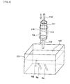
- a first embodiment of a method for producing a metallic-sodium-filled engine valve of the present invention is described based on Figs. 1 , 2 .
- a cylinder is denoted by reference numeral 111 and is provided with a nozzle 112 on a leading end side.
- a piston is denoted by reference numeral 113 and is disposed in the cylinder 111 to be slidingly moveable.
- a piston rod is denoted by reference numeral 114 and is connected to the piston 113 to cause the piston 113 to move.
- a heater is denoted by reference numeral 115 and is disposed to cover an outer periphery of the cylinder 111 and also configured to be capable of heating the inside of the cylinder 111 and keeping it warm (for example, about 120°C to 300°C).
- Reference numeral 121 denotes a container and a hydrocarbon-based liquid 120 such as an oil is put in the container 121.
- the cylinder 111 is arranged above the container 121 with the nozzle 112 facing downward; a piece of solid metallic sodium Na cut out in a predetermined size is put into an inside of the cylinder 111 and the piston 113 is inserted into the inside of the cylinder 111; the heater 115 is activated to heat and melt the piece of metallic sodium Na to a liquid state; the piston 113 is then pushed by using the piston rod 114 and the metallic sodium Na melted to a liquid state is thereby discharged linearly (in a bar shape) from the nozzle 112; and the discharged piece of metallic sodium Na falls into the hydrocarbon-based liquid 120 in the container 121 and is cooled to a room temperature to be solidified while maintaining its linear shape (bar shape).
- a dry inert gas atmosphere such as a dry nitride gas
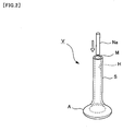
- the bar-shaped piece of metallic sodium Na of a predetermined amount is inserted from an opening M at an upper end of a stem portion S in such a way that the bar-shaped piece of metallic sodium Na is put into a hollow portion H in an inner portion of the stem portion S. Thereafter, the opening M is closed. Thus, an engine valve V filled inside with the predetermined amount of metallic sodium Na can be obtained.
- metallic sodium Na heated and melted to a liquid state is discharged linearly (in a bar shape) into the hydrocarbon-based liquid 120, cooled to the room temperature to be solidified, and is then inserted into the hollow portion H from the opening M of the stem portion S.
- the bar-shaped piece of metallic sodium Na can be easily shaped without performing extrusion and the predetermined amount of metallic sodium Na can be easily put into the hollow portion H without heating (98°C or higher) the stem portion S of the engine valve V.
- the predetermined amount of metallic sodium Na can be easily put into the inside of the engine valve V.
- Patent Literature 2 and the like have the following problem.
- metallic sodium Na is cooled and solidified by causing coolant such as liquid nitrogen to flow out from a nozzle when the metallic sodium Na heated and melted is sent out from the nozzle.
- coolant such as liquid nitrogen
- frost is formed on a surface of cooled metallic sodium Na.
- the metallic sodium Na heated and melted is cooled and solidified by causing the metallic sodium Na to fall into the hydrocarbon-based liquid 120.
- frost on the surface of cooled metallic sodium Na can be surely prevented.
- a second embodiment of a method for producing a metallic-sodium-filled engine valve of the present invention is described based on Figs. 3 , 4 . Note that, portions same as the first embodiment are denoted with the same reference numerals as those used in the descriptions of the aforementioned first embodiment and descriptions which overlap with the descriptions of the aforementioned first embodiment are omitted.
- a metal mold is denoted by reference numeral 220 and is configured such that a bar-shaped space 220a whose end portions respectively on both sides are tapered is formed by causing a top face of a lower mold 221 and a bottom face of an upper mold 222 to overlap each other.
- a communication port 222a communicating the space 220a and a space above the top face thereof is formed.
- the nozzle 112 is inserted into the communication port 222a in the upper mold 222 of the metal mold 220; a piece of solid metallic sodium Na cut out in a predetermined size is put into an inside of the cylinder 111 and the piston 113 is inserted into the inside of the cylinder 111; the heater 115 is activated to heat and melt the piece of metallic sodium Na to a liquid state; and the piston 113 is then pushed by using the piston rod 114 and the metallic sodium Na melted to a liquid state is thereby injected into the space 220a from the communication port 222a of the metal mold 220 through the nozzle 112.
- a dry inert gas atmosphere such as a dry nitride gas
- the nozzle 112 is removed from the communication port 222a of the metal mold 220 and the metal mold 220 is then left to cool to a room temperature.
- the metallic sodium Na in the space 220a of the metal mold 220 is solidified into a piece having a shape of the space 220a, i.e. the bar shape whose end portions respectively on both sides are tapered.
- the lower mold 221 and the upper mold 222 of the metal mold 220 are separated from each other and the piece of metallic sodium Na solidified in the bar shape having the tapered end portions is taken out.
- the piece of metallic sodium Na is inserted from the opening M at the upper end of the stem portion S in such a way that the piece of metallic sodium Na is put into the hollow portion H in the inner portion of the stem portion S. Thereafter, the opening M is closed.
- the engine valve V filled inside with the predetermined amount of metallic sodium Na can be obtained.
- the bar-shaped piece of metallic sodium Na is shaped as follows.
- the metallic sodium Na heated and melted to a liquid state is discharged linearly (in a bar shape) into the hydrocarbon-based liquid 120 and then cooled to the room temperature to be solidified.
- the bar-shaped piece of metallic sodium Na having the tapered end portions is shaped as follows. The metallic sodium Na heated and melted to a liquid state is injected into the space 220a in the metal mold 220 from the communication port 222a of the metal mold 220 and then cooled to the room temperature to be solidified.
- the bar-shaped piece of metallic sodium Na can be easily shaped without performing extrusion and metallic sodium Na can be put into the hollow portion H without heating (98°C or higher) the stem portion S of the engine valve V, as similar to the first embodiment.
- the predetermined amount of metallic sodium Na can be easily put into the inside of the engine valve V as in the first embodiment as a matter of course. Furthermore, it is possible to easily obtain the bar-shaped piece of metallic sodium Na shaped such that end portions thereof respectively on both sides are tapered, i.e. the bar-shaped piece of metallic sodium Na which can be easily inserted into the elongated hollow portion H (a diameter of about 2 to 4 mm). In addition, the piece of metallic sodium Na can be inserted into the inside of the engine valve V more easily.
- the piece of metallic sodium Na may be obtained as follows.
- the metallic sodium Na discharged linearly (in a bar shape) is caused to continuously fall into the hydrocarbon-based liquid 120 and then cooled to be solidified in such a way that an elongated bar material of metallic sodium Na is obtained. Thereafter, the bar material is cut in a required length and the cut piece is put into the hollow portion H of the engine valve V.
- the piece of metallic sodium Na may be obtained as follows.
- the metallic sodium Na is caused to intermittently fall into the hydrocarbon-based liquid 120 and then cooled to be solidified in such a way that bar materials of the required length are obtained. Thereafter, each of the bar materials can be inserted into the hollow portion H of the engine valve V without being cut.
- the bar-shaped piece of metallic sodium can be easily shaped without performing extrusion and the predetermined amount of metallic sodium can be easily put into the hollow portion without heating the stem portion of the engine valve.
- the method can be used very effectively in the industrial field.
Landscapes
- Engineering & Computer Science (AREA)
- Mechanical Engineering (AREA)
- General Engineering & Computer Science (AREA)
- Fuel-Injection Apparatus (AREA)
- Molds, Cores, And Manufacturing Methods Thereof (AREA)
- Pistons, Piston Rings, And Cylinders (AREA)
Abstract
Description
- The present invention relates to a method for producing an engine valve filled inside with metallic sodium.
- In an engine valve of an automobile or the like, in order to respond to an increase in performance, a reduction in fuel consumption of an engine, and the like, the weight is reduced and the heat transmission is increased by filling an inside of the engine valve with metallic sodium.
- Such an engine valve has a stem portion which has a hollow portion formed in an inner portion and which has an opening formed at an upper end. To this stem portion, for example, (1) solid metallic sodium is extruded into a bar shape, cut into a predetermined length, and then inserted into the hollow portion from the opening; or (2) solid metallic sodium is heated to melt (about 120°C to 300°C) into a liquid state and then put into the hollow portion by injecting a predetermined amount of metallic sodium into the hollow portion from the opening. Thereafter, the opening is sealed and the engine valve is thus produced (for example, see
Patent Literatures 1 to 3 and the like listed below). -
- Patent Literature 1: Japanese Patent Application Publication No.
Hei 03-018605 - Patent Literature 2: Japanese Patent Application Publication No.
Hei 04-232318 - Patent Literature 3: Japanese Patent Application Publication No.
Hei 04-272413 - However, a conventional method for producing a metallic-sodium-filled engine valve as described above has the following problems.
-
- (1) Solid metallic sodium is difficult to extrude and the workability of shaping the solid metallic sodium is thereby poor.
- (2) When liquid metallic sodium adheres to an inner wall of the elongated hollow portion (a diameter of about 2 to 4 mm) during the injection of liquid metallic sodium into the hollow portion, metallic sodium immediately cools and becomes solid thereby closing the hollow portion. Thus, the liquid metallic sodium needs to be injected while the stem portion is heated (98°C or higher) and the workability of injection is thereby poor.
- The present invention is made in view of the problems describe above, and an object thereof is to provide a method for producing a metallic-sodium-filled engine valve by which metallic sodium can be easily put into the inside of an engine valve.
- In a method for producing an engine valve filled inside with metallic sodium, according to a first aspect of the invention for solving the aforementioned problems, the engine valve is produced by: putting metallic sodium into a hollow portion from an opening of a stem portion having the hollow portion in an inner portion and having the opening at an upper end; and thereafter sealing the opening, the method characterized by comprising: cooling and solidifying metallic sodium heated and melted to a liquid state into a bar-shaped piece; and thereafter inserting the bar-shaped piece of metallic sodium into the hollow portion from the opening of the stem portion.
- The method for producing a metallic-sodium-filled engine valve according to a second aspect of the invention is characterized in that, in the first aspect of the invention, the metallic sodium heated and melted to a liquid state is discharged linearly into a hydrocarbon-based liquid and is cooled to be solidified into the bar-shaped piece.
- The method for producing a metallic-sodium-filled engine valve according to a third aspect of the invention is characterized in that, in the first aspect of the invention, the metallic sodium heated and melted to a liquid state is injected into a bar-shaped space in an inside of a metal mold having the space in the inside and is then cooled to be solidified into the bar-shaped piece.
- The method for producing a metallic-sodium-filled engine valve according to a fourth aspect of the invention is characterized in that, in the third aspect of the invention, the bar-shaped space of the metal mold is formed such that at least an end portion on one side is formed in a tapered shape or an elongated ellipse shape.
- In the method for producing a metallic-sodium-filled engine valve of the present invention, the metallic sodium heated and melted to a liquid state is cooled to be solidified into a bar-shaped piece and the bar-shaped piece of metallic sodium is thereafter inserted into the hollow portion from the opening of the stem portion. Thus, the bar-shaped piece of metallic sodium can be easily shaped without performing extrusion and a predetermined amount of metallic sodium can be easily put into the hollow portion without heating the stem portion of the engine valve.
-
- [
Fig. 1] Fig. 1 is a view for explaining a first embodiment of a method for producing a metallic-sodium-filled engine valve of the present invention. - [
Fig. 2] Fig. 2 is an explanatory view subsequent toFig. 1 . - [
Fig. 3] Fig. 3 is a view for explaining a second embodiment of a method for producing a metallic-sodium-filled engine valve of the present invention. - [
Fig. 4] Fig. 4 is an explanatory view subsequent toFig. 3 . - Embodiments of a method for producing a metallic-sodium-filled engine valve of the present invention are described below based on the drawings. However, the present invention is not limited to the embodiments described below based on the drawings.
- A first embodiment of a method for producing a metallic-sodium-filled engine valve of the present invention is described based on
Figs. 1 ,2 . - In
Fig. 1 , a cylinder is denoted byreference numeral 111 and is provided with anozzle 112 on a leading end side. A piston is denoted byreference numeral 113 and is disposed in thecylinder 111 to be slidingly moveable. A piston rod is denoted byreference numeral 114 and is connected to thepiston 113 to cause thepiston 113 to move. A heater is denoted byreference numeral 115 and is disposed to cover an outer periphery of thecylinder 111 and also configured to be capable of heating the inside of thecylinder 111 and keeping it warm (for example, about 120°C to 300°C).Reference numeral 121 denotes a container and a hydrocarbon-basedliquid 120 such as an oil is put in thecontainer 121. - In a dry inert gas atmosphere such as a dry nitride gas: the
cylinder 111 is arranged above thecontainer 121 with thenozzle 112 facing downward; a piece of solid metallic sodium Na cut out in a predetermined size is put into an inside of thecylinder 111 and thepiston 113 is inserted into the inside of thecylinder 111; theheater 115 is activated to heat and melt the piece of metallic sodium Na to a liquid state; thepiston 113 is then pushed by using thepiston rod 114 and the metallic sodium Na melted to a liquid state is thereby discharged linearly (in a bar shape) from thenozzle 112; and the discharged piece of metallic sodium Na falls into the hydrocarbon-basedliquid 120 in thecontainer 121 and is cooled to a room temperature to be solidified while maintaining its linear shape (bar shape). - Next, as shown in
Fig. 2 , the bar-shaped piece of metallic sodium Na of a predetermined amount is inserted from an opening M at an upper end of a stem portion S in such a way that the bar-shaped piece of metallic sodium Na is put into a hollow portion H in an inner portion of the stem portion S. Thereafter, the opening M is closed. Thus, an engine valve V filled inside with the predetermined amount of metallic sodium Na can be obtained. - In other words, in the embodiment, metallic sodium Na heated and melted to a liquid state is discharged linearly (in a bar shape) into the hydrocarbon-based
liquid 120, cooled to the room temperature to be solidified, and is then inserted into the hollow portion H from the opening M of the stem portion S. - Thus, in the embodiment, the bar-shaped piece of metallic sodium Na can be easily shaped without performing extrusion and the predetermined amount of metallic sodium Na can be easily put into the hollow portion H without heating (98°C or higher) the stem portion S of the engine valve V.
- Accordingly, in the embodiment, the predetermined amount of metallic sodium Na can be easily put into the inside of the engine valve V.
- Moreover, Patent Literature 2 and the like have the following problem. In Patent Literature 2, metallic sodium Na is cooled and solidified by causing coolant such as liquid nitrogen to flow out from a nozzle when the metallic sodium Na heated and melted is sent out from the nozzle. Thus, moisture in the air is also cooled and frost is formed on a surface of cooled metallic sodium Na. As a result, the moisture and the metallic sodium Na react with each other. However, in the embodiment, the metallic sodium Na heated and melted is cooled and solidified by causing the metallic sodium Na to fall into the hydrocarbon-based
liquid 120. Thus, the formation of frost on the surface of cooled metallic sodium Na can be surely prevented. - A second embodiment of a method for producing a metallic-sodium-filled engine valve of the present invention is described based on
Figs. 3 ,4 . Note that, portions same as the first embodiment are denoted with the same reference numerals as those used in the descriptions of the aforementioned first embodiment and descriptions which overlap with the descriptions of the aforementioned first embodiment are omitted. - In
Fig. 3 , a metal mold is denoted byreference numeral 220 and is configured such that a bar-shaped space 220a whose end portions respectively on both sides are tapered is formed by causing a top face of alower mold 221 and a bottom face of anupper mold 222 to overlap each other. In a top face of theupper mold 222, acommunication port 222a communicating thespace 220a and a space above the top face thereof is formed. - In a dry inert gas atmosphere such as a dry nitride gas: the
nozzle 112 is inserted into thecommunication port 222a in theupper mold 222 of themetal mold 220; a piece of solid metallic sodium Na cut out in a predetermined size is put into an inside of thecylinder 111 and thepiston 113 is inserted into the inside of thecylinder 111; theheater 115 is activated to heat and melt the piece of metallic sodium Na to a liquid state; and thepiston 113 is then pushed by using thepiston rod 114 and the metallic sodium Na melted to a liquid state is thereby injected into thespace 220a from thecommunication port 222a of themetal mold 220 through thenozzle 112. - After a predetermined amount of metallic sodium Na is injected into the
space 220a of themetal mold 220, thenozzle 112 is removed from thecommunication port 222a of themetal mold 220 and themetal mold 220 is then left to cool to a room temperature. When themetal mold 220 cools, the metallic sodium Na in thespace 220a of themetal mold 220 is solidified into a piece having a shape of thespace 220a, i.e. the bar shape whose end portions respectively on both sides are tapered. - Next, the
lower mold 221 and theupper mold 222 of themetal mold 220 are separated from each other and the piece of metallic sodium Na solidified in the bar shape having the tapered end portions is taken out. Then, as shown inFig. 4 , the piece of metallic sodium Na is inserted from the opening M at the upper end of the stem portion S in such a way that the piece of metallic sodium Na is put into the hollow portion H in the inner portion of the stem portion S. Thereafter, the opening M is closed. Thus, the engine valve V filled inside with the predetermined amount of metallic sodium Na can be obtained. - In the first embodiment, the bar-shaped piece of metallic sodium Na is shaped as follows. The metallic sodium Na heated and melted to a liquid state is discharged linearly (in a bar shape) into the hydrocarbon-based
liquid 120 and then cooled to the room temperature to be solidified. However, in the second embodiment, the bar-shaped piece of metallic sodium Na having the tapered end portions is shaped as follows. The metallic sodium Na heated and melted to a liquid state is injected into thespace 220a in themetal mold 220 from thecommunication port 222a of themetal mold 220 and then cooled to the room temperature to be solidified. - Thus, in the second embodiment, the bar-shaped piece of metallic sodium Na can be easily shaped without performing extrusion and metallic sodium Na can be put into the hollow portion H without heating (98°C or higher) the stem portion S of the engine valve V, as similar to the first embodiment.
- Accordingly, in the second embodiment, the predetermined amount of metallic sodium Na can be easily put into the inside of the engine valve V as in the first embodiment as a matter of course. Furthermore, it is possible to easily obtain the bar-shaped piece of metallic sodium Na shaped such that end portions thereof respectively on both sides are tapered, i.e. the bar-shaped piece of metallic sodium Na which can be easily inserted into the elongated hollow portion H (a diameter of about 2 to 4 mm). In addition, the piece of metallic sodium Na can be inserted into the inside of the engine valve V more easily.
- In the aforementioned first embodiment, the piece of metallic sodium Na may be obtained as follows. The metallic sodium Na discharged linearly (in a bar shape) is caused to continuously fall into the hydrocarbon-based
liquid 120 and then cooled to be solidified in such a way that an elongated bar material of metallic sodium Na is obtained. Thereafter, the bar material is cut in a required length and the cut piece is put into the hollow portion H of the engine valve V. Alternatively, the piece of metallic sodium Na may be obtained as follows. The metallic sodium Na is caused to intermittently fall into the hydrocarbon-basedliquid 120 and then cooled to be solidified in such a way that bar materials of the required length are obtained. Thereafter, each of the bar materials can be inserted into the hollow portion H of the engine valve V without being cut. - In the aforementioned second embodiment, descriptions are given of the case where the bar shaped piece of metallic sodium Na whose end portions respectively on both sides are tapered is shaped with the
metal mold 220. However, as other embodiments, a bar-shaped piece of metallic sodium Na whose end portion on one side alone is tapered or a bar-shaped piece of metallic sodium Na having an elongated ellipse shape may be shaped with a metal mold, for example. Even in such cases, operational effects similar to the case of the aforementioned second embodiment can be obtained. - Moreover, in the aforementioned second embodiment, descriptions are given of the case where the bar-shaped piece of metallic sodium Na is obtained one by one by using the
metal mold 220 having thesingle space 220a. However, as another embodiment, it is also possible to obtain multiple bar-shaped pieces of metallic sodium Na simultaneously by using, for example, a metal mold having multiple spaces. - In the method for producing a metallic-sodium-filled engine valve of the present invention, the bar-shaped piece of metallic sodium can be easily shaped without performing extrusion and the predetermined amount of metallic sodium can be easily put into the hollow portion without heating the stem portion of the engine valve. Thus, the method can be used very effectively in the industrial field.
-
- 111
- cylinder
- 111a
- discharge port
- 112
- piston
- 113
- piston rod
- 114
- heater
- 120
- hydrocarbon-based liquid
- 121
- container
- 220
- metal mold
- 220a
- space
- 221
- lower mold
- 222
- upper mold
- 222a
- communication port
- Na
- metallic sodium
- V
- engine valve
- A
- umbrella portion
- S
- stem portion
- H
- hollow portion
- M
- opening
Claims (4)
- A method for producing an engine valve filled inside with metallic sodium, the engine valve produced by: putting metallic sodium into a hollow portion from an opening of a stem portion having the hollow portion in an inner portion and having the opening at an upper end; and thereafter sealing the opening, the method characterized by comprising:cooling and solidifying metallic sodium heated and melted to a liquid state into a bar-shaped piece; andthereafter inserting the bar-shaped piece of metallic sodium into the hollow portion from the opening of the stem portion.
- The method for producing a metallic-sodium-filled engine valve according to claim 1, characterized in that the metallic sodium heated and melted to a liquid state is discharged linearly into a hydrocarbon-based liquid and is cooled to be solidified into the bar-shaped piece.
- The method for producing a metallic-sodium-filled engine valve according to claim 1, characterized in that the metallic sodium heated and melted to a liquid state is injected into a bar-shaped space in an inside of a metal mold having the space in the inside and is then cooled to be solidified into the bar-shaped piece.
- The method for producing a metallic-sodium-filled engine valve according to claim 3, characterized in that the bar-shaped space of the metal mold is formed such that at least an end portion on one side is formed in a tapered shape or an elongated ellipse shape.
Applications Claiming Priority (2)
| Application Number | Priority Date | Filing Date | Title |
|---|---|---|---|
| JP2010041409A JP2011179327A (en) | 2010-02-26 | 2010-02-26 | Method for manufacturing metal sodium-sealed engine valve |
| PCT/JP2010/068004 WO2011104923A1 (en) | 2010-02-26 | 2010-10-14 | Method for producing metallic-sodium-filled engine valve |
Publications (2)
| Publication Number | Publication Date |
|---|---|
| EP2541001A1 true EP2541001A1 (en) | 2013-01-02 |
| EP2541001A4 EP2541001A4 (en) | 2013-10-16 |
Family
ID=44506361
Family Applications (1)
| Application Number | Title | Priority Date | Filing Date |
|---|---|---|---|
| EP10846586.5A Withdrawn EP2541001A4 (en) | 2010-02-26 | 2010-10-14 | Method for producing metallic-sodium-filled engine valve |
Country Status (5)
| Country | Link |
|---|---|
| US (1) | US20120246936A1 (en) |
| EP (1) | EP2541001A4 (en) |
| JP (1) | JP2011179327A (en) |
| CN (1) | CN102762825A (en) |
| WO (1) | WO2011104923A1 (en) |
Cited By (2)
| Publication number | Priority date | Publication date | Assignee | Title |
|---|---|---|---|---|
| DE102013220366A1 (en) | 2013-10-09 | 2015-04-09 | Mahle International Gmbh | dosing |
| CN107775289A (en) * | 2017-10-25 | 2018-03-09 | 江苏金山动力科技有限公司 | Hollow valve for filling low-melting alloy and preparation method thereof |
Families Citing this family (8)
| Publication number | Priority date | Publication date | Assignee | Title |
|---|---|---|---|---|
| CN102767406A (en) * | 2012-08-13 | 2012-11-07 | 中国南方航空工业(集团)有限公司 | Sodium filling device and sodium filling method |
| JP6163212B2 (en) * | 2013-11-21 | 2017-07-12 | 日鍛バルブ株式会社 | Manufacturing method of hollow poppet valve |
| DE102014225618A1 (en) * | 2014-12-11 | 2016-06-16 | Mahle International Gmbh | Method for producing a hollow valve |
| PL3214280T3 (en) * | 2015-10-28 | 2019-09-30 | Nittan Valve Co., Ltd. | Method for supplying inert gas into poppet valve intermediate and device for supplying inert gas into poppet valve intermediate |
| CN108138610B (en) * | 2016-01-29 | 2021-03-12 | 日锻汽门株式会社 | Method for filling metallic sodium |
| WO2019180806A1 (en) | 2018-03-20 | 2019-09-26 | 日鍛バルブ株式会社 | Hollow exhaust poppet valve |
| WO2020100185A1 (en) | 2018-11-12 | 2020-05-22 | 日鍛バルブ株式会社 | Method for manufacturing engine poppet valve |
| WO2021199190A1 (en) | 2020-03-30 | 2021-10-07 | 日鍛バルブ株式会社 | Method for manufacturing engine poppet valve |
Family Cites Families (14)
| Publication number | Priority date | Publication date | Assignee | Title |
|---|---|---|---|---|
| FR917196A (en) * | 1944-06-26 | 1946-12-27 | Thompson Prod Inc | A method of making hollow lift valves incorporating a cooling agent such as sodium |
| US2693624A (en) * | 1951-09-28 | 1954-11-09 | Du Pont | Continuous casting of metals |
| US3579624A (en) * | 1969-03-07 | 1971-05-18 | Weston Chemical Corp | Insulated alkali metal conductor |
| GB1270206A (en) * | 1969-11-20 | 1972-04-12 | Eaton Yale & Towne | Valve and method of production |
| RO93037B1 (en) * | 1985-08-27 | 1988-01-01 | îNTREPRINDEREA "23 AUGUST" | Process and device for crimping tubular rod of sodium-filled discharge valves |
| JP2670529B2 (en) | 1989-06-14 | 1997-10-29 | フジオーゼックス株式会社 | Method and apparatus for injecting metallic sodium into hollow engine valve |
| DE4024084A1 (en) * | 1989-11-29 | 1991-06-06 | Daimler Benz Ag | METHOD FOR PRODUCING HOLLOW GAS EXCHANGE VALVES FOR LIFTING PISTON MACHINES |
| JP2832757B2 (en) | 1990-12-28 | 1998-12-09 | フジオーゼックス株式会社 | Device for inserting metallic sodium into hollow valve |
| JPH04272413A (en) * | 1991-02-27 | 1992-09-29 | Mitsubishi Heavy Ind Ltd | Filling method for metallic sodium |
| JPH07102917A (en) * | 1993-09-30 | 1995-04-18 | Mitsubishi Heavy Ind Ltd | Sodium-enclosed hollow engine valve manufacturing method |
| JPH07119421A (en) * | 1993-10-25 | 1995-05-09 | Mitsubishi Heavy Ind Ltd | Manufacture of na-sealed hollow engine valve |
| US5814944A (en) * | 1996-01-22 | 1998-09-29 | Matsushita Electric Works, Ltd. | High pressure sodium vapor lamp with high color rendering |
| JP4390291B1 (en) * | 2008-09-18 | 2009-12-24 | 株式会社 吉村カンパニー | Method for manufacturing valve head part of hollow engine valve and hollow engine valve |
| JP5485011B2 (en) * | 2010-05-12 | 2014-05-07 | 三菱重工業株式会社 | Manufacturing method of engine valve filled with sodium metal |
-
2010
- 2010-02-26 JP JP2010041409A patent/JP2011179327A/en active Pending
- 2010-10-14 CN CN2010800581160A patent/CN102762825A/en active Pending
- 2010-10-14 WO PCT/JP2010/068004 patent/WO2011104923A1/en not_active Ceased
- 2010-10-14 EP EP10846586.5A patent/EP2541001A4/en not_active Withdrawn
- 2010-10-14 US US13/504,924 patent/US20120246936A1/en not_active Abandoned
Cited By (2)
| Publication number | Priority date | Publication date | Assignee | Title |
|---|---|---|---|---|
| DE102013220366A1 (en) | 2013-10-09 | 2015-04-09 | Mahle International Gmbh | dosing |
| CN107775289A (en) * | 2017-10-25 | 2018-03-09 | 江苏金山动力科技有限公司 | Hollow valve for filling low-melting alloy and preparation method thereof |
Also Published As
| Publication number | Publication date |
|---|---|
| US20120246936A1 (en) | 2012-10-04 |
| WO2011104923A1 (en) | 2011-09-01 |
| CN102762825A (en) | 2012-10-31 |
| JP2011179327A (en) | 2011-09-15 |
| EP2541001A4 (en) | 2013-10-16 |
Similar Documents
| Publication | Publication Date | Title |
|---|---|---|
| US20120246936A1 (en) | Method for producing metallic-sodium-filled engine valve | |
| US8713793B2 (en) | Method for producing metallic-sodium-filled engine valve | |
| US9377151B2 (en) | Method for manufacturing an insulated pipe using a bag | |
| WO2009069716A1 (en) | Production method of internal gear and internal gear made of metallic glass | |
| US20140186652A1 (en) | Process to manufacture a metal foam provided with channels and metal foam thus produced | |
| AR059013A1 (en) | A FROZEN CONFITERIA PRODUCT AND MANUFACTURING METHOD | |
| US8367135B2 (en) | Method of producing ice-candy | |
| US8561297B2 (en) | Method for producing engine valve in which sodium metal is sealed | |
| US7798806B2 (en) | Two-piece bottom insert for a mold cavity | |
| CN106536089A (en) | Method for manufacturing a two-component blade for a gas turbine engine and blade obtained by such a method | |
| KR20200056683A (en) | Cooling apparatus having ultra thin cooling pathway and manufacturing method thereof | |
| EP3290664B1 (en) | Method and device for manufacturing metallic-sodium-filled engine valve | |
| US20090324770A1 (en) | Bottom Insert With Heat Insulation | |
| CN108138610A (en) | The fill method of metallic sodium | |
| EP3167977B1 (en) | Mold apparatus for molding metal in high vacuum environment | |
| US20170003084A1 (en) | Absorption body for a capsule containing a phase-change material | |
| US10107562B2 (en) | Heat pipe and sealing method thereof | |
| CN214605748U (en) | Cigarette bullet shell forming die | |
| KR101503593B1 (en) | Low pressure die casting machine for casting magnesium | |
| WO2001003905A1 (en) | Valve gating arrangement for an insulated runner | |
| CN106584771A (en) | Injection molding process of syringe | |
| CN217121648U (en) | Casting mould | |
| CN203695911U (en) | Die casting mold with good sealing performance | |
| CN108580837A (en) | Cooled vacuum head for high-pressure casting mold | |
| CU20150011A7 (en) | A PROCEDURE TO ISOLATE THE FILLING CONTENT OF A FOOD PRODUCT |
Legal Events
| Date | Code | Title | Description |
|---|---|---|---|
| PUAI | Public reference made under article 153(3) epc to a published international application that has entered the european phase |
Free format text: ORIGINAL CODE: 0009012 |
|
| 17P | Request for examination filed |
Effective date: 20120419 |
|
| AK | Designated contracting states |
Kind code of ref document: A1 Designated state(s): AL AT BE BG CH CY CZ DE DK EE ES FI FR GB GR HR HU IE IS IT LI LT LU LV MC MK MT NL NO PL PT RO RS SE SI SK SM TR |
|
| DAX | Request for extension of the european patent (deleted) | ||
| A4 | Supplementary search report drawn up and despatched |
Effective date: 20130916 |
|
| RIC1 | Information provided on ipc code assigned before grant |
Ipc: B21K 1/22 20060101ALI20130910BHEP Ipc: F01L 3/20 20060101AFI20130910BHEP Ipc: F01L 3/24 20060101ALI20130910BHEP Ipc: B23P 15/00 20060101ALI20130910BHEP Ipc: F01L 3/14 20060101ALI20130910BHEP |
|
| STAA | Information on the status of an ep patent application or granted ep patent |
Free format text: STATUS: THE APPLICATION HAS BEEN WITHDRAWN |
|
| 18W | Application withdrawn |
Effective date: 20140507 |