EP2540856A1 - Forging of glassy aluminum-based alloys - Google Patents
Forging of glassy aluminum-based alloys Download PDFInfo
- Publication number
- EP2540856A1 EP2540856A1 EP12162571A EP12162571A EP2540856A1 EP 2540856 A1 EP2540856 A1 EP 2540856A1 EP 12162571 A EP12162571 A EP 12162571A EP 12162571 A EP12162571 A EP 12162571A EP 2540856 A1 EP2540856 A1 EP 2540856A1
- Authority
- EP
- European Patent Office
- Prior art keywords
- forging
- billet
- devitrified
- forged
- die
- Prior art date
- Legal status (The legal status is an assumption and is not a legal conclusion. Google has not performed a legal analysis and makes no representation as to the accuracy of the status listed.)
- Withdrawn
Links
Images
Classifications
-
- C—CHEMISTRY; METALLURGY
- C22—METALLURGY; FERROUS OR NON-FERROUS ALLOYS; TREATMENT OF ALLOYS OR NON-FERROUS METALS
- C22C—ALLOYS
- C22C21/00—Alloys based on aluminium
-
- B—PERFORMING OPERATIONS; TRANSPORTING
- B21—MECHANICAL METAL-WORKING WITHOUT ESSENTIALLY REMOVING MATERIAL; PUNCHING METAL
- B21C—MANUFACTURE OF METAL SHEETS, WIRE, RODS, TUBES, PROFILES OR LIKE SEMI-MANUFACTURED PRODUCTS OTHERWISE THAN BY ROLLING; AUXILIARY OPERATIONS USED IN CONNECTION WITH METAL-WORKING WITHOUT ESSENTIALLY REMOVING MATERIAL
- B21C23/00—Extruding metal; Impact extrusion
- B21C23/002—Extruding materials of special alloys so far as the composition of the alloy requires or permits special extruding methods of sequences
-
- B—PERFORMING OPERATIONS; TRANSPORTING
- B21—MECHANICAL METAL-WORKING WITHOUT ESSENTIALLY REMOVING MATERIAL; PUNCHING METAL
- B21J—FORGING; HAMMERING; PRESSING METAL; RIVETING; FORGE FURNACES
- B21J1/00—Preparing metal stock or similar ancillary operations prior, during or post forging, e.g. heating or cooling
- B21J1/003—Selecting material
- B21J1/006—Amorphous metal
-
- B—PERFORMING OPERATIONS; TRANSPORTING
- B21—MECHANICAL METAL-WORKING WITHOUT ESSENTIALLY REMOVING MATERIAL; PUNCHING METAL
- B21K—MAKING FORGED OR PRESSED METAL PRODUCTS, e.g. HORSE-SHOES, RIVETS, BOLTS OR WHEELS
- B21K3/00—Making engine or like machine parts not covered by sub-groups of B21K1/00; Making propellers or the like
- B21K3/04—Making engine or like machine parts not covered by sub-groups of B21K1/00; Making propellers or the like blades, e.g. for turbines; Upsetting of blade roots
-
- C—CHEMISTRY; METALLURGY
- C22—METALLURGY; FERROUS OR NON-FERROUS ALLOYS; TREATMENT OF ALLOYS OR NON-FERROUS METALS
- C22C—ALLOYS
- C22C1/00—Making non-ferrous alloys
- C22C1/11—Making amorphous alloys
-
- C—CHEMISTRY; METALLURGY
- C22—METALLURGY; FERROUS OR NON-FERROUS ALLOYS; TREATMENT OF ALLOYS OR NON-FERROUS METALS
- C22F—CHANGING THE PHYSICAL STRUCTURE OF NON-FERROUS METALS AND NON-FERROUS ALLOYS
- C22F1/00—Changing the physical structure of non-ferrous metals or alloys by heat treatment or by hot or cold working
- C22F1/04—Changing the physical structure of non-ferrous metals or alloys by heat treatment or by hot or cold working of aluminium or alloys based thereon
-
- C—CHEMISTRY; METALLURGY
- C21—METALLURGY OF IRON
- C21D—MODIFYING THE PHYSICAL STRUCTURE OF FERROUS METALS; GENERAL DEVICES FOR HEAT TREATMENT OF FERROUS OR NON-FERROUS METALS OR ALLOYS; MAKING METAL MALLEABLE, e.g. BY DECARBURISATION OR TEMPERING
- C21D2201/00—Treatment for obtaining particular effects
- C21D2201/03—Amorphous or microcrystalline structure
-
- F—MECHANICAL ENGINEERING; LIGHTING; HEATING; WEAPONS; BLASTING
- F05—INDEXING SCHEMES RELATING TO ENGINES OR PUMPS IN VARIOUS SUBCLASSES OF CLASSES F01-F04
- F05D—INDEXING SCHEME FOR ASPECTS RELATING TO NON-POSITIVE-DISPLACEMENT MACHINES OR ENGINES, GAS-TURBINES OR JET-PROPULSION PLANTS
- F05D2230/00—Manufacture
- F05D2230/20—Manufacture essentially without removing material
- F05D2230/25—Manufacture essentially without removing material by forging
-
- F—MECHANICAL ENGINEERING; LIGHTING; HEATING; WEAPONS; BLASTING
- F05—INDEXING SCHEMES RELATING TO ENGINES OR PUMPS IN VARIOUS SUBCLASSES OF CLASSES F01-F04
- F05D—INDEXING SCHEME FOR ASPECTS RELATING TO NON-POSITIVE-DISPLACEMENT MACHINES OR ENGINES, GAS-TURBINES OR JET-PROPULSION PLANTS
- F05D2300/00—Materials; Properties thereof
- F05D2300/10—Metals, alloys or intermetallic compounds
- F05D2300/17—Alloys
- F05D2300/173—Aluminium alloys, e.g. AlCuMgPb
Definitions
- Aluminum alloys are important in many industries. Glassy Al-based alloys and their devitrified derivatives are currently being considered for applications in the aerospace industry. These alloys involve the addition of rare earth and transition metal elements. These alloys have high strength and, when processed appropriately, have high ductility.
- One of the key requirements for high ductility is control of the second phase size during thermomechanical processing; in this case, forging extruded billet into various forged shapes.
- the alloys are heated, such as to 700 °F to 800 °F (370°C to 425°C), and are forged at high press speeds. There is normally no concern for adiabatic heating because the alloys are usually heat-treatable. In a heat treatment, they are solutionized, quenched and aged to a desired temper after forging.
- Al-based alloys such as Al-Y-Ni-Co alloys are devitrified glass-forming aluminum alloys that derive their strength from a nanometer-sized grain structure and nanometer-sized intermetallic second phase or phases. Examples of such alloys are disclosed in co-owned U.S. Patents No, 6,974,510 and 7,413,621 .
- the invention involves the forging of extruded billet, or forging mults, in a direction whose axis is parallel to the axis of extrusion that formed the alloy billet.
- the alloy itself is a devitrified derivative of glassy aluminum alloys such as those described in the above identified patents.
- aluminum based alloys containing from 3 to 18.5 atomic percent nickel and 3 to 14.0 atomic percent yttrium.
- the alloy billet is textured and has an axis of extrusion in which the microstructure is aligned. Forging in this direction changes the microstructure to give maximum strength, and also causes the plate phases within the subject alloys to become randomly oriented, resulting in improved ductility.
- the present invention provides a method of forging devitrified aluminum alloys, comprising the steps of: selecting a devitrified aluminum alloy billet having an axis of extrusion; placing the billet in a plane strain forging die so the axis of extrusion is parallel to the direction of forging; forging the billet in the plane strain forging die to elongate the billet in the horizontal direction; removing the billet and placing it in a blocker die or series of blocker dies having a desired shape such that the original axis of extrusion is aligned with the axis of the forging die; and forging the billet in the product forging final die to produce a forged billet having a desired shape.
- the present invention provides a forged devitrified aluminum alloy having a desired shape, comprising: a devitrified aluminum alloy billet having an axis of extrusion; the alloy having been forged in a plane strain forging die so the axis of extrusion is parallel to the direction of forging; the billet having been elongated in the horizontal direction; and the billet further having been forged in a product forming forging die having a desired shape such that the original axis of extrusion is aligned with the axis of the forging die resulting in the desired shape.
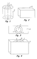
- FIG. 1 is a schematic view of an alloy billet inserted in a cylinder.
- FIG. 2 is a schematic view of a forging die.
- FIG. 3 is a schematic view of the cylinder and billet of FIG. 1 inserted into the die of FIG. 2
- FIG. 4 is a schematic view of the die of FIG. 3 with the billet just below the lip of the die.
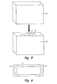
- FIG. 5 is a schematic view of the use of a punch inserted into the die and billet of FIG. 4 .
- FIG. 6 is a schematic view of the billet after forging in FIG. 5 .
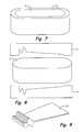
- FIG. 7 is a schematic view of the billet after being extracted from the die of FIG. 6 .
- FIG. 8 is a schematic view of the extracted billet of FIG. 7 inserted into a forging die such that the forging direction is parallel to the axis of extrusion.
- FIG. 9 is a schematic view of a part produced by the forging in FIG. 8 .
- FIG. 10 is a view of the microstructure of an alloy billet
- An alloy billet 11 that, for example, is 4 inches (10cm) in diameter and 36 inches (99cm) tall, is potted in a two inch diameter cylinder 13 of aluminum alloy 6061 or other such metals, as shown in Fig. 1 .
- Billet 11 may be formed from any devitrified aluminum alloy, such as an aluminum based alloy containing from 3 to 18.5 atomic percent nickel and 3 to 14.0 atomic percent yttrium.
- Cylinder 13 with billet 11 is then put in a steel plane strain die 15 in Figs. 2 and 3 , where die 15 is wider than cylinder 13.
- Billet 11 is aligned so that its extrusion axis 17 will be parallel to the axis of forging in plane strain forge die 15 and is just below the lip 15a of die 15, as seen in Fig. 4 .
- Fig. 5 punch 19 is inserted into die 15 and plane strain forges billet 11 into the shape shown in Fig. 6 .
- a maximum amount of work is placed in the direction of extrusion, axis 17.
- billet 11 is elongated in the horizontal direction so as to prepare billet 11 for further processing to form a useful part such as an airfoil.
- Fig. 7 shows the elongated billet 11 after it is removed from die 15.
- Billet 11 is then placed in a forging die 21, shown in Fig. 8 for forming an airfoil.
- Such forging dies could include blocker dies and a final forging die. Again, the forging is done in the direction of extrusion axis 17.
- Airfoil 23 is the result of forging in die 21.
- the plate phases Al 23 Ni 6 Y 4 and Al 19 Ni 5 Y 3 ) that give the alloy its strength, become aligned with the extrusion direction 17. This leads to low ductility in the extrusion direction and even lower ductility in the transverse direction.
- axis 17 the plate phases become randomly oriented and smaller in size. This leads to more uniform flow during plastic deformation, resulting in improved ductility.
- the temperature of the forged product must be controlled. This is accomplished through careful control of the temperature of the dies and the billet.
- the temperature of the dies typically ranges from 500 °F to about 800 °F (260 °C to 426.7 °C). For more control, this temperature is maintained from about 675 °F to about 750 °F (357.2 °C to 398.9 °C) during forging the billet.
- the billet temperature is also controlled to be at a temperature from about 500 °F to about 800 °F (260 °C to 426.7 °C).
- a temperature range from about 700 °F to about 750 °F (371.1 °C to 398.9 °C) during forging the billet.
- adiabatic heating is controlled by controlling the press speed. Good results have been attained at a press speed of from about 0.001 inches per second to 0.1 inches per second (0.0025 to 0.25 cm per second).
Landscapes
- Chemical & Material Sciences (AREA)
- Engineering & Computer Science (AREA)
- Mechanical Engineering (AREA)
- Materials Engineering (AREA)
- Metallurgy (AREA)
- Organic Chemistry (AREA)
- Physics & Mathematics (AREA)
- Thermal Sciences (AREA)
- Crystallography & Structural Chemistry (AREA)
- Forging (AREA)
Abstract
A method of forging devitrified aluminum alloys to a desired shape. The alloy (11) is forged in a plane strain forging die (15) with the axis of extrusion (17) being parallel to the direction of forging. The alloy is then forged in a product forming forging die (21) having a desired shape such that the original axis of extrusion is aligned with the axis of the forging die resulting in the desired shape
Description
- Aluminum alloys are important in many industries. Glassy Al-based alloys and their devitrified derivatives are currently being considered for applications in the aerospace industry. These alloys involve the addition of rare earth and transition metal elements. These alloys have high strength and, when processed appropriately, have high ductility.
- One of the key requirements for high ductility is control of the second phase size during thermomechanical processing; in this case, forging extruded billet into various forged shapes.
- When pure Al or Al-based alloys are forged, the alloys are heated, such as to 700 °F to 800 °F (370°C to 425°C), and are forged at high press speeds. There is normally no concern for adiabatic heating because the alloys are usually heat-treatable. In a heat treatment, they are solutionized, quenched and aged to a desired temper after forging.
- Al-based alloys such as Al-Y-Ni-Co alloys are devitrified glass-forming aluminum alloys that derive their strength from a nanometer-sized grain structure and nanometer-sized intermetallic second phase or phases. Examples of such alloys are disclosed in co-owned
U.S. Patents No, 6,974,510 and7,413,621 . - However, devitrified derivatives of glassy aluminum alloys have nanocrystalline microstructures that have mechanical properties that cannot be obtained when starting out with powder in the crystalline state. Standard forging practices will destroy the nanocrystalline microstructure and the important properties are lost.
- The invention involves the forging of extruded billet, or forging mults, in a direction whose axis is parallel to the axis of extrusion that formed the alloy billet. The alloy itself is a devitrified derivative of glassy aluminum alloys such as those described in the above identified patents.
- Of particular use are aluminum based alloys containing from 3 to 18.5 atomic percent nickel and 3 to 14.0 atomic percent yttrium.
- The alloy billet is textured and has an axis of extrusion in which the microstructure is aligned. Forging in this direction changes the microstructure to give maximum strength, and also causes the plate phases within the subject alloys to become randomly oriented, resulting in improved ductility.
- The present invention provides a method of forging devitrified aluminum alloys, comprising the steps of: selecting a devitrified aluminum alloy billet having an axis of extrusion; placing the billet in a plane strain forging die so the axis of extrusion is parallel to the direction of forging; forging the billet in the plane strain forging die to elongate the billet in the horizontal direction; removing the billet and placing it in a blocker die or series of blocker dies having a desired shape such that the original axis of extrusion is aligned with the axis of the forging die; and forging the billet in the product forging final die to produce a forged billet having a desired shape.
- In another aspect the present invention provides a forged devitrified aluminum alloy having a desired shape, comprising: a devitrified aluminum alloy billet having an axis of extrusion; the alloy having been forged in a plane strain forging die so the axis of extrusion is parallel to the direction of forging; the billet having been elongated in the horizontal direction; and the billet further having been forged in a product forming forging die having a desired shape such that the original axis of extrusion is aligned with the axis of the forging die resulting in the desired shape.
- Certain preferred embodiment will now be described by way of example only and with reference to the accompanying drawings.
-
FIG. 1 is a schematic view of an alloy billet inserted in a cylinder. -
FIG. 2 is a schematic view of a forging die. -
FIG. 3 is a schematic view of the cylinder and billet ofFIG. 1 inserted into the die ofFIG. 2 -
FIG. 4 is a schematic view of the die ofFIG. 3 with the billet just below the lip of the die. -
FIG. 5 is a schematic view of the use of a punch inserted into the die and billet ofFIG. 4 . -
FIG. 6 is a schematic view of the billet after forging inFIG. 5 . -
FIG. 7 is a schematic view of the billet after being extracted from the die ofFIG. 6 . -
FIG. 8 is a schematic view of the extracted billet ofFIG. 7 inserted into a forging die such that the forging direction is parallel to the axis of extrusion. -
FIG. 9 is a schematic view of a part produced by the forging inFIG. 8 . - FIG. 10 is a view of the microstructure of an alloy billet
- An
alloy billet 11 that, for example, is 4 inches (10cm) in diameter and 36 inches (99cm) tall, is potted in a twoinch diameter cylinder 13 of aluminum alloy 6061 or other such metals, as shown inFig. 1 .Billet 11 may be formed from any devitrified aluminum alloy, such as an aluminum based alloy containing from 3 to 18.5 atomic percent nickel and 3 to 14.0 atomic percent yttrium. -
Cylinder 13 withbillet 11 is then put in a steel plane strain die 15 inFigs. 2 and 3 , where die 15 is wider thancylinder 13.Billet 11 is aligned so that itsextrusion axis 17 will be parallel to the axis of forging in plane strain forge die 15 and is just below thelip 15a of die 15, as seen inFig. 4 . - In
Fig. 5 ,punch 19 is inserted into die 15 and plane strain forgesbillet 11 into the shape shown inFig. 6 . In this process, a maximum amount of work is placed in the direction of extrusion,axis 17. At the same time,billet 11 is elongated in the horizontal direction so as to preparebillet 11 for further processing to form a useful part such as an airfoil. -
Fig. 7 shows theelongated billet 11 after it is removed from die 15.Billet 11 is then placed in aforging die 21, shown inFig. 8 for forming an airfoil. Such forging dies could include blocker dies and a final forging die. Again, the forging is done in the direction ofextrusion axis 17. Airfoil 23 is the result of forging in die 21. - During extrusion to form
billet 11, the plate phases (Al23Ni6Y4 and Al19Ni5Y3) that give the alloy its strength, become aligned with theextrusion direction 17. This leads to low ductility in the extrusion direction and even lower ductility in the transverse direction. When forged parallel to the direction of extrusion,axis 17, the plate phases become randomly oriented and smaller in size. This leads to more uniform flow during plastic deformation, resulting in improved ductility. - To provide for the retention of the nano-scale microstructure during forging, the temperature of the forged product must be controlled. This is accomplished through careful control of the temperature of the dies and the billet. The temperature of the dies typically ranges from 500 °F to about 800 °F (260 °C to 426.7 °C). For more control, this temperature is maintained from about 675 °F to about 750 °F (357.2 °C to 398.9 °C) during forging the billet. The billet temperature is also controlled to be at a temperature from about 500 °F to about 800 °F (260 °C to 426.7 °C). Again, more control will use a temperature range from about 700 °F to about 750 °F (371.1 °C to 398.9 °C) during forging the billet. During forging, adiabatic heating is controlled by controlling the press speed. Good results have been attained at a press speed of from about 0.001 inches per second to 0.1 inches per second (0.0025 to 0.25 cm per second).
- Once the product has been formed, normal finish operations are performed. In the airfoil of
Fig. 9 , the forging path resulted in high yield strength and high ductility perpendicular to the chord direction for a blade. This is important for bird strike capability. - While the invention has been described with reference to an exemplary embodiment(s), it will be understood by those skilled in the art that various changes may be made and equivalents may be substituted for elements thereof without departing from the scope of the invention defined by the claims. In addition, many modifications may be made to adapt a particular situation or material to the teachings of the invention without departing from the essential scope thereof. Therefore, it is intended that the invention not be limited to the particular embodiment(s) disclosed, but that the invention will include all embodiments falling within the scope of the appended claims.
- The following clauses set out features of the invention which may not presently be claimed but which may form the basis for future amendment or a divisional application.
- 1. A method of forging devitrified aluminum alloys, comprising the steps of:
- selecting a devitrified aluminum alloy billet having an axis of extrusion;
- placing the billet in a plane strain forging die so the axis of extrusion is parallel to the direction of forging;
- forging the billet in the plane strain forging die at a temperature of the die from about 500 °F to about 800 °F (260 °C to 426.7 °C) to elongate the billet in the horizontal direction while maintaining the temperature of the billet at a temperature from about 500 °F to about 800 °F (260 °C to 426.7 °C);
- removing the billet and placing it in a blocker die or series of blocker dies having a desired shape such that the original axis of extrusion is aligned with the axis of the forging die; and
- forging the billet in the product forging final die at a temperature of the die from about 500 °F to about 800 °F (260 °C to 426.7 °C) to produce a forged billet having a desired shape.
- 2. The method of clause 1, wherein the temperature of the die ranges from about 675 °F to about 750 °F (357.2 °C to 398.9 °C) during plane strain forging the billet.
- 3. The method of clause 1, wherein the plane strain forging is done at a press speed of from about 0.001 inches per second to 0.1 inches per second.
- 4. The method of clause 1, wherein the temperature of the billet ranges from about 700 °F to about 750 °F (371.1 °C to 398.9 °C) during plane strain forging the billet.
- 5. The method of clause 1, wherein the devitrified aluminum alloy is an aluminum based alloy containing from 3 to 18.5 atomic percent nickel and 3 to 14.0 atomic percent yttrium.
Claims (15)
- A method of forging devitrified aluminum alloys, comprising the steps of:selecting a devitrified aluminum alloy billet (11) having an axis of extrusion;
placing the billet in a plane strain forging die (15) so the axis of extrusion (17) is parallel to the direction of forging;
forging the billet in the plane strain forging die to elongate the billet in the horizontal direction;
removing the billet and placing it in a blocker die or series of blocker dies having a desired shape such that the original axis of extrusion is aligned with the axis of the forging die;and
forging the billet in the product forging final die to produce a forged billet having a desired shape. - The method of claim 1, wherein the plane strain forging die (15) and product forging die during forging the billet (11) is maintained at a temperature from about 500 °F to about 800 °F (260 °C to 426.7 °C).
- The method of claim 2, wherein the temperature ranges from about 675 °F to about 750 °F (357.2 °C to 398.9 °C) during forging the billet (11).
- The method of claim 1, 2 or 3, wherein the plane strain forging is done at a press speed of from about 0.001 inches per second to 0.1 inches per second (0.0025 to 0.25 cm per second).
- The method of any preceding claim, wherein the billet (11) during forging the billet is maintained at a temperature from about 500 °F to about 800 °F (260 °C to 426.7 °C).
- The method of claim 5, wherein the temperature ranges from about 700 °F to about 750 °F (371.1 °C to 398.9 °C) during forging the billet.
- The method of any preceding claim, wherein the devitrified aluminum alloy is an aluminum based alloy containing from 3 to 18.5 atomic percent nickel and 3 to 14.0 atomic percent yttrium.
- A forged devitrified aluminum alloy made according to the method of any preceding claim.
- A forged devitrified aluminum alloy having a desired shape, comprising:a devitrified aluminum alloy billet (11) having an axis of extrusion (17);the alloy having been forged in a plane strain forging die (15) so the axis of extrusion is parallel to the direction of forging;the billet having been elongated in the horizontal direction; andthe billet further having been forged in a product forming forging die having a desired shape such that the original axis of extrusion is aligned with the axis of the forging die resulting in the desired shape.
- The forged devitrified aluminum alloy of claim 9, wherein the plane strain forging die and the product forging during forging the billet were maintained at a temperature from about 500 °F to about 800 °F (260 °C to 426.7 °C).
- The forged devitrified aluminum alloy of claim 10, wherein the temperature ranged from about 675 °F to about 750 °F (357.2 °C to 398.9 °C) during plane strain forging the billet.
- The forged devitrified aluminum alloy of claim 9, 10 or 11, wherein the plane strain forging was done at a press speed of from about 0.001 inches per second to 0.1 inches per second.
- The forged devitrified aluminum alloy of any one of claims 9 to 12, wherein the billet during forging the billet was maintained at a temperature from about 500 °F to about 800 °F (260 °C to (426.7 °C).
- The forged devitrified aluminum alloy of claim 13, wherein the temperature ranged from about 700 °F to about 750 °F (371.1 °C to 398.9 °C) during plane strain forging the billet.
- The forged devitrified aluminum alloy of any one of claims 9 to 14, wherein the devitrified aluminum alloy is an aluminum based alloy containing from 3 to 18.5 atomic percent nickel and 3 to 14.0 atomic percent yttrium.
Applications Claiming Priority (1)
| Application Number | Priority Date | Filing Date | Title |
|---|---|---|---|
| US13/169,210 US20120328472A1 (en) | 2011-06-27 | 2011-06-27 | Forging of glassy aluminum-based alloys |
Publications (1)
| Publication Number | Publication Date |
|---|---|
| EP2540856A1 true EP2540856A1 (en) | 2013-01-02 |
Family
ID=45930616
Family Applications (1)
| Application Number | Title | Priority Date | Filing Date |
|---|---|---|---|
| EP12162571A Withdrawn EP2540856A1 (en) | 2011-06-27 | 2012-03-30 | Forging of glassy aluminum-based alloys |
Country Status (2)
| Country | Link |
|---|---|
| US (1) | US20120328472A1 (en) |
| EP (1) | EP2540856A1 (en) |
Families Citing this family (4)
| Publication number | Priority date | Publication date | Assignee | Title |
|---|---|---|---|---|
| CN102947022B (en) * | 2010-06-22 | 2016-03-16 | 斯沃奇集团研究和开发有限公司 | Assembly method |
| WO2015006466A1 (en) | 2013-07-10 | 2015-01-15 | United Technologies Corporation | Aluminum alloys and manufacture methods |
| CN114603072B (en) * | 2022-01-13 | 2023-04-14 | 上海交通大学 | A method for forging small blades of titanium diboride-7075 aluminum matrix composites based on induction heating |
| CN119426505A (en) * | 2024-11-19 | 2025-02-14 | 哈尔滨工业大学 | A method for preparing a titanium-aluminum intermetallic compound disk with uniform structure and performance |
Citations (2)
| Publication number | Priority date | Publication date | Assignee | Title |
|---|---|---|---|---|
| US6974510B2 (en) | 2003-02-28 | 2005-12-13 | United Technologies Corporation | Aluminum base alloys |
| US20080308197A1 (en) * | 2007-06-15 | 2008-12-18 | United Technologies Corporation | Secondary processing of structures derived from AL-RE-TM alloys |
-
2011
- 2011-06-27 US US13/169,210 patent/US20120328472A1/en not_active Abandoned
-
2012
- 2012-03-30 EP EP12162571A patent/EP2540856A1/en not_active Withdrawn
Patent Citations (3)
| Publication number | Priority date | Publication date | Assignee | Title |
|---|---|---|---|---|
| US6974510B2 (en) | 2003-02-28 | 2005-12-13 | United Technologies Corporation | Aluminum base alloys |
| US7413621B2 (en) | 2003-02-28 | 2008-08-19 | United Technologies Corporation | Aluminum base alloys |
| US20080308197A1 (en) * | 2007-06-15 | 2008-12-18 | United Technologies Corporation | Secondary processing of structures derived from AL-RE-TM alloys |
Non-Patent Citations (1)
| Title |
|---|
| DUTTA A ET AL: "Deformation behavior of an ultrafine-grained Al-Ni-Y-Co-Sc alloy", MATERIALS SCIENCE AND ENGINEERING A: STRUCTURAL MATERIALS:PROPERTIES, MICROSTRUCTURE & PROCESSING, LAUSANNE, CH, vol. 513-514, 15 July 2009 (2009-07-15), pages 239 - 246, XP026086626, ISSN: 0921-5093, [retrieved on 20090319], DOI: 10.1016/J.MSEA.2009.03.012 * |
Also Published As
| Publication number | Publication date |
|---|---|
| US20120328472A1 (en) | 2012-12-27 |
Similar Documents
| Publication | Publication Date | Title |
|---|---|---|
| KR102039770B1 (en) | Split-pass open-die forging for hard-to-forge, strain-path sensitive titanium-base and nickel-base alloys | |
| EP2324137B1 (en) | Process for forming aluminium alloy sheet components | |
| KR20150129644A (en) | Thermomechanical processing of alpha-beta titanium alloys | |
| EP2520679A1 (en) | Method of controlling grain size in forged precipitation-strengthened alloys and components formed thereby | |
| CN105441840B (en) | A kind of hammering cogging method of high-strength heat-resistant magnesium alloy ingot casting | |
| JP2009215631A (en) | Titanium-aluminum-based alloy and production method therefor, and moving blade using the same | |
| JP2010280002A (en) | Method for manufacturing forged piece from gamma titanium-aluminum-based alloy | |
| EP2540856A1 (en) | Forging of glassy aluminum-based alloys | |
| JP4782987B2 (en) | Magnesium-based alloy screw manufacturing method | |
| US10011885B2 (en) | Methods for producing titanium and titanium alloy articles | |
| US7617750B2 (en) | Process of producing nanocrystalline bodies | |
| RU2301845C1 (en) | Method of production of items from high-temperature wrought nickel alloy | |
| RU2371512C1 (en) | Method of product receiving from heatproof nickel alloy | |
| RU2345173C1 (en) | Method of producing superductile plates from aluminium alloys of aluminium-magnesium-lithium system | |
| US8603267B2 (en) | Extrusion of glassy aluminum-based alloys | |
| Miura et al. | Ultrafine grain evolution in Mg alloys, AZ31, AZ61, AZ91 by multi directional forging | |
| RU2707006C1 (en) | Method of forging workpieces with ultra-fine-grained structure of two-phase titanium alloys | |
| RU2583564C1 (en) | Method of producing forgings from heat-resistant granular alloys | |
| Jafarzadeh et al. | Study of the cyclic extrusion–compression in production of high stringed and ultrafine grained AM60 Magnesium noncircular thin section beams | |
| RU2614294C1 (en) | Method of blades forgings manufacturing from titanium alloys | |
| JP5249367B2 (en) | Magnesium-based alloy screw | |
| Vilotic et al. | Severe Plastic Deformation-Key Features, Methods and Application | |
| Bochniak et al. | Nano grained structure in KOBO extruded bulk products | |
| Imayev et al. | Principles of fabrication of bulk ultrafine-grained and nanostructured materials by multiple isothermal forging |
Legal Events
| Date | Code | Title | Description |
|---|---|---|---|
| PUAI | Public reference made under article 153(3) epc to a published international application that has entered the european phase |
Free format text: ORIGINAL CODE: 0009012 |
|
| AK | Designated contracting states |
Kind code of ref document: A1 Designated state(s): AL AT BE BG CH CY CZ DE DK EE ES FI FR GB GR HR HU IE IS IT LI LT LU LV MC MK MT NL NO PL PT RO RS SE SI SK SM TR |
|
| AX | Request for extension of the european patent |
Extension state: BA ME |
|
| STAA | Information on the status of an ep patent application or granted ep patent |
Free format text: STATUS: THE APPLICATION IS DEEMED TO BE WITHDRAWN |
|
| 18D | Application deemed to be withdrawn |
Effective date: 20130703 |