EP2540658A1 - Cap fastening device - Google Patents
Cap fastening device Download PDFInfo
- Publication number
- EP2540658A1 EP2540658A1 EP11744703A EP11744703A EP2540658A1 EP 2540658 A1 EP2540658 A1 EP 2540658A1 EP 11744703 A EP11744703 A EP 11744703A EP 11744703 A EP11744703 A EP 11744703A EP 2540658 A1 EP2540658 A1 EP 2540658A1
- Authority
- EP
- European Patent Office
- Prior art keywords
- cap
- chuck
- motor
- speed reducer
- torque limiter
- Prior art date
- Legal status (The legal status is an assumption and is not a legal conclusion. Google has not performed a legal analysis and makes no representation as to the accuracy of the status listed.)
- Granted
Links
- 239000003638 chemical reducing agent Substances 0.000 claims abstract description 56
- 230000005540 biological transmission Effects 0.000 claims abstract description 13
- 230000033001 locomotion Effects 0.000 claims description 21
- 230000000694 effects Effects 0.000 description 3
- 230000001133 acceleration Effects 0.000 description 2
- 230000008878 coupling Effects 0.000 description 1
- 238000010168 coupling process Methods 0.000 description 1
- 238000005859 coupling reaction Methods 0.000 description 1
- 238000012423 maintenance Methods 0.000 description 1
- 239000000843 powder Substances 0.000 description 1
Images




Classifications
-
- B—PERFORMING OPERATIONS; TRANSPORTING
- B67—OPENING, CLOSING OR CLEANING BOTTLES, JARS OR SIMILAR CONTAINERS; LIQUID HANDLING
- B67B—APPLYING CLOSURE MEMBERS TO BOTTLES JARS, OR SIMILAR CONTAINERS; OPENING CLOSED CONTAINERS
- B67B3/00—Closing bottles, jars or similar containers by applying caps
- B67B3/20—Closing bottles, jars or similar containers by applying caps by applying and rotating preformed threaded caps
- B67B3/204—Linear-type capping machines
- B67B3/2053—Linear-type capping machines comprising capping heads
-
- B—PERFORMING OPERATIONS; TRANSPORTING
- B67—OPENING, CLOSING OR CLEANING BOTTLES, JARS OR SIMILAR CONTAINERS; LIQUID HANDLING
- B67B—APPLYING CLOSURE MEMBERS TO BOTTLES JARS, OR SIMILAR CONTAINERS; OPENING CLOSED CONTAINERS
- B67B3/00—Closing bottles, jars or similar containers by applying caps
- B67B3/20—Closing bottles, jars or similar containers by applying caps by applying and rotating preformed threaded caps
- B67B3/2073—Closing bottles, jars or similar containers by applying caps by applying and rotating preformed threaded caps comprising torque limiting means
-
- B—PERFORMING OPERATIONS; TRANSPORTING
- B67—OPENING, CLOSING OR CLEANING BOTTLES, JARS OR SIMILAR CONTAINERS; LIQUID HANDLING
- B67B—APPLYING CLOSURE MEMBERS TO BOTTLES JARS, OR SIMILAR CONTAINERS; OPENING CLOSED CONTAINERS
- B67B3/00—Closing bottles, jars or similar containers by applying caps
- B67B3/20—Closing bottles, jars or similar containers by applying caps by applying and rotating preformed threaded caps
- B67B3/2073—Closing bottles, jars or similar containers by applying caps by applying and rotating preformed threaded caps comprising torque limiting means
- B67B3/208—Electrical means responsive to the torque applied and acting on motor control means, e.g. strain gauges or power measurement means
Definitions
- the present invention relates to a cap fastening apparatus.
- a cap fastening apparatus As a cap fastening apparatus, as described in Patent Document 1, there is a structure in which a rotation of a motor is decelerated by a speed reducer so as to be transmitted to a chuck, and a cap gripped by the chuck is threadably attached to a bottle.
- the cap fastening apparatus described in Patent Document 1 is structured such that a torque limiter which is an apparatus for disconnecting a transmission of the rotation from the motor to the chuck at a time when a rotational resistance of the chuck becomes larger than a set torque is interposed between the speed reducer and the chuck.
- Patent Document 1 Japanese Patent Application Laid-Open (JP-A) No. 2004-123109
- the cap fastening apparatus described in Patent Document 1 has the following problems:
- a weight of the torque limiter apparatus becomes larger, and a total weight of the cap fastening apparatus in a state in which the torque limiter apparatus is attached to the chuck becomes larger.
- a moving apparatus which is used for moving the cap fastening apparatus from a cap delivery position to a cap fastening position or the like becomes larger in size.
- an outside dimension of the torque limiter apparatus becomes larger, and a total dimension becomes larger in size in a cap fastening facility which is provided with plural sets of the torque limiter apparatuses, the speed reducers and the chucks side by side, and can simultaneously fasten a plurality of caps to a plurality of bottles, respectively.
- a weight of the torque limiter apparatus becomes larger, a moment of inertia thereof becomes larger, a precision of a fastening torque of the cap which is limited by the torque limiter apparatus is lowered, and a value of the fastening torque applied to the cap becomes unstable.
- a cap driving apparatus which drives the cap to the bottle is not provided in the cap fastening apparatus. Even if it is intended to arrange the cap driving apparatus above a center axis of the chuck for providing the cap driving apparatus, the torque limiter apparatus is arranged on the center axis of the chuck. Accordingly, there is a risk that an impact blow which the cap driving apparatus applies to the torque limiter apparatus and the chuck directly acts on the torque limiter apparatus to damage it. The cap driving apparatus cannot be easily provided in the cap fastening apparatus.
- An object of the present invention is to downsize a capacity of a torque limiter apparatus limiting a set torque which is necessary for fastening a cap by a chuck, in a cap fastening apparatus which threadably attaches the cap to a bottle by the chuck which is rotated by a motor.
- Another object of the present invention is to easily provide a cap driving apparatus in the cap fastening apparatus.
- a cap fastening apparatus in which a rotation of a motor is transmitted to a chuck while being decelerated by a speed reducer, and a cap gripped by the chuck is threadably attached to a bottle.
- a torque limiter apparatus is interposed between the motor and the speed reducer, the torque limiter apparatus disconnecting a transmission of a rotation from the motor to the chuck at a time when a rotational resistance of the chuck becomes larger than a set torque.
- a reduction gear ratio of the speed reducer is set to be equal to or more than 1/2 and equal to or less than 1/10.
- the cap fastening apparatus which threadably attaches the cap to the bottle by the chuck rotated by the motor, it is possible to downsize a capacity of the torque limiter apparatus limiting the set torque which is necessary for fastening the cap by the chuck.
- the cap driving apparatus can be easily provided in the cap fastening apparatus.
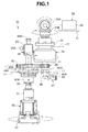
- a cap fastening apparatus 10 is structured, as shown in FIG. 1 and FIG. 2 , such that a rotation of a motor 20 is transmitted to a chuck 50 via a torque limiter apparatus 30 and a speed reducer 40, and a cap 1 can be threadably attached to a bottle 2 by a set torque.
- the cap fastening apparatus 10 can drive the cap 1 to the bottle 2.
- the cap fastening apparatus 10 supports the motor 20, the torque limiter apparatus 30 and the speed reducer 40 in a supporting plate 11 which is supported to a stand (which is not illustrated in FIG. 1 and FIG. 2 ) so as to be movable in a back and forth direction and an up and down direction.
- a rotation of the motor 20 is decelerated by the speed reducer 40 so as to be transmitted to the chuck 50.
- the cap 1 which is gripped by the chuck 50 is threadably attached to the bottle 2.
- the torque limiter apparatus 30 which is interposed between the motor 20 and the speed reducer 40 and disconnects a transmission of the rotation from the motor 20 to the chuck 50 is actuated and the transmission is disconnected, whereby the cap 1 can be threadably attached to the bottle 2.
- a normal motor 20 for example, an inverter motor in which a speed can be set
- a vertical bevel gear 21A which is provided in a rotating shaft of the motor 20 is engaged with a transverse bevel gear 21B which is provided in an input shaft of the torque limiter apparatus 30, thereby transmitting the rotation of the motor 20 to the torque limiter apparatus 30 and changing the rotation in a horizontal direction of the rotating shaft of the motor 20 into a vertical direction which is in parallel to a center axis of the chuck 50.
- a case 22 of the motor 20 is fixed and supported to the supporting plate 11.
- the torque limiter apparatus 30 is not particularly limited in its type. As one example, there can be employed a pneumatic type which can connect and disconnect the transmission of the set torque on the basis of a dynamic friction force between opposite friction discs. As another example, the torque limiter apparatus 30 can employ a magnet type which can connect and disconnect the transmission of the set torque on the basis of a magnetic force between opposite magnets.
- the pneumatic type torque limiter apparatus 30 is structured such that the opposite friction discs generate a friction powder, however, is inexpensive.
- the magnet type torque limiter apparatus 30 is structured such that the opposite magnets are not in contact with each other, and is semipermanently in maintenance free. A case 31 of the torque limiter apparatus 30 is fixed and supported to the supporting plate 11.
- the speed reducer 40 can be constructed by an intermeshing gear train of a small gear 41 and a large gear 42.
- the rotation of the motor 20 is decelerated by a reduction gear ratio R (1/3 in the present embodiment) which is constructed by a gear ratio (1:3 in the present embodiment) of the small gear 41 and the larger gear 42, and is transmitted to the chuck 50.
- An aspect of the speed reducer 40 is not limited to a combination of spur gears such as the present embodiment, but can be optionally selected, for example, a speed reducer constructed by gears in accordance with the other aspect, a combination of a belt and a pulley and the like.
- the reduction gear ratio R is preferably set to be about equal to or more than 1/2 and equal to or less than 1/10.
- a drive shaft 43 is fixed to a boss 41A of the small gear 41, an output shaft of the torque limiter apparatus 30 is connected to the drive shaft 43, and a bearing housing 43A pivotally supporting the drive shaft 43 is fixed and supported to the supporting plate 11.
- a bearing housing 44A pivotally supporting a boss 42A of the large gear 42 is fixed and supported to the supporting plate 11.
- a driven shaft 45 is constructed by a spline shaft, and the boss 42A is a spline shaft receiver.
- a ball spline is preferable since it has a high precision and a high rigidity.
- the boss 42A is provided with the driven shaft 45 which is connected in such a manner as to be integral in a rotating direction and be movable in an axial direction. It is preferable that an axis of the driven shaft 45 is deviated from an axis of the drive shaft 43 of the speed reducer 40 without coming into line with it, and they are in parallel to each other. In particular, it is preferable that the driven shaft 45 and the drive shaft 43 of the speed reducer 40 are arranged in parallel.
- the chuck 50 is structured such that various chuck heads 52 which are used by being replaced in correspondence to a dimension and a shape of the cap 1 can be attached to and detached from a coupler 51 which is fixed to a lower end portion of the driven shaft 45 of the speed reducer 40.
- the chuck 50 supports a slide 54 to a vertical direction guide rod 53 which is fixed to the supporting plate 11 so as to be movable up and down, makes the driven shaft 45 pass through an inner periphery of a pneumatic manifold 55 which is provided in the slide 54 so as to be integrally and relatively rotatable in an axial direction, feeds a compressed air which is supplied from an air intake port 55A of the pneumatic manifold 55 to the chuck head 52 via a hollow portion of the driven shaft 45, and opens and closes the chuck head 52 on the basis of a pneumatic force so as to grip the cap 1.
- An axis of the chuck 50 comes into line with an axis of the driven shaft 45. In other words, it is preferable that the axis of the chuck 50 is deviated from the axis of the drive shaft 43 of the speed reducer 40 without coming into line with it, and they are in parallel to each other.
- the driven shaft 45 is provided in such a manner as to be movable in an axial direction with respect to the large gear 42 which is supported to the supporting plate 11.
- the chuck 50 and the driven shaft 45 positions a positioning stopper 48 which is provided below the pneumatic manifold 55 locked to the driven shaft 45 in the axial direction, at a lowest position which comes into contact with an upper surface of the large gear 42, on the basis of a gravitational force acting on the chuck 50.
- the positioning stopper 48 is fixed to an appropriate position of the driven shaft 45.
- an upper end portion of the driven shaft 45 protrudes to an upper portion of the pneumatic manifold 55 so as to form an impact blow portion 45A.
- a cap driving apparatus which is not illustrated is arranged above the impact blow portion 45A of the driven shaft 45.
- the cap driving apparatus is driven by an air cylinder, a motor-driven cylinder or the like, and the cap driving apparatus has a driving head which drives the impact blow portion 45A.
- the torque limiter apparatus 30 is arranged on the axis of the drive shaft 43 of the speed reducer 40, and the chuck 50 is arranged on the axis of the driven shaft 45 which is in parallel to the drive shaft 43 of the speed reducer 40, whereby the screw cap 1 which is gripped to the chuck head 52 of the chuck 50 can be threadably attached to an opening portion of the bottle 2 by a fixed torque on the basis of the rotation of the motor 20.
- the supporting plate 11 comes down in such a manner as to attach the cap 1 gripped by the chuck head 52 of the chuck 50 to the above of the opening portion of the bottle 2, at a time of threadably attaching the cap 1 by the motor 20.
- FIG. 1 and FIG. 2 show a state in which the driven gear 45 approximately moves up to an upper limit with respect to the large gear 42.
- An upper limit position at a time of moving upward is a position at which an upper portion of the coupler 51 which is larger than an outer diameter of the driven shaft 45 comes into contact with the boss 42A.
- the motor 20 has a clutch type brake (the clutch type brake may be embedded in the motor 20, or may be attached to the rotating shaft of the motor 20).
- the rotation of the motor 20 can be immediately transmitted to the torque limiter apparatus 30, the speed reducer 40 and the chuck 50 sequentially by releasing the clutch type brake of the motor 20 at a time of starting the threadable attachment of the cap 1 by the motor 20.
- a change of a rotating condition for example, a rotation deceleration or a rotation stop of a rotating dog 46 provided in the drive shaft 43 of the speed reducer 40 is read by a sensor 47 which is provided around the dog 46, and a control apparatus which is not illustrated disconnects in a moment the transmission of the rotation of the motor 20 by the clutch type brake of the motor 20, in accordance with the change of the rotating condition which is ready by the sensor 47, immediately releases the grip of the cap 1 by the chuck 50, and can finish the capping work by the cap fastening apparatus 10.
- a control of a fastening torque of the cap 1 by the cap fastening apparatus 10 is carried out by the torque limiter apparatus 30, and the clutch of the motor 20 does not take part in the control of the fastening torque of the cap 1.
- the motor 20 which can carry out a rapid acceleration and a rapid deceleration of the servo motor, the stepping motor or the like, in place of use of the motor 20 having the clutch type brake, it is possible to immediately transmit the rotation of the motor 20 to the torque limiter apparatus 30, the speed reducer 40 and the chuck 50 sequentially, at a time of starting the threadable attachment as mentioned above. At a time of finishing the threadable attachment, it is possible to stop the rotation of the motor 20 in a moment, to immediately release the grip of the cap 1 by the chuck 50, and to finish the capping work by the cap fastening apparatus 10.
- clutch indicates a structure which disconnects a rotating motion from an input shaft to an output shaft and a torque transmission on the basis of a control signal or any operation from an external portion.
- a means for preventing a torque beyond a set value of the input shaft from being transmitted to the output shaft is constructed by the torque limiter apparatus.
- the driven shaft 45 is provided in such a manner as to be movable in the axial direction with respect to the large gear 42 of the speed reducer 40, and the drive cap 1 can be driven to the opening portion of the bottle 2 by a drive head (not illustrated) which is provided in a lower end portion of the driven shaft 45, on the basis of a movement in the axial direction of the driven shaft 45.
- the drive head which is provided in the lower end portion of the driven shaft 45 of the speed reducer 40 locates at a position which corresponds to an appropriate driving operation position with respect to the opening portion of the bottle 2, on the basis of the rotation of the driven shaft 45, and the drive head and the cap 1 are mounted on the opening portion of the bottle 2, on the basis of a downward movement of the supporting plate 11.
- the driven shaft 45 existing at the lowest position with respect to the large gear 42 of the speed reducer 40 moves up with respect to the large gear 42.
- the downward movement of the cap 1 at a time when the cap driving apparatus which is not illustrated subsequently drives the impact blow portion 45A in the upper end portion of the driven shaft 45 so as to drive the cap 1 to the opening portion of the bottle 2 is allowed within the range of the amount of the upward movement mentioned above with respect to the large gear 42 of the driven shaft 45.
- the cap fastening facility 100 is structured, as shown in FIG. 3 , such that a stand 101 is provided with a cap supplying chute 102, the cap supplying chute 102 is provided with a subsequent cap separating and supplying conveyor 103, and the cap 1 which is supplied from the cap supplying chute 102 can be transferred to a plurality of cap separating and supplying plates 104 which are arranged in a cap separating and supplying zone formed as one row on the cap separating and supplying conveyor 103.
- the cap fastening facility 100 is provided with a container feeding conveyor 105 in a front surface of the cap separating and supplying conveyor 103, and can feed while accommodating the bottle 2 in each of the plurality of container feeding skirts 106 which are formed as one row on the container feeding conveyor 105 and are arranged in a cap fastening zone.
- the cap separating and supplying plates 104 are arranged in the cap separating and supplying zone on the cap separating and supplying conveyor 103, the skirts 106 are arranged in the cap fastening zone on the container feeding conveyor 105, and each of the cap separating and supplying plates 104 and each of the skirts 106 correspond to each other in one-to-one relationship.
- the cap fastening facility 100 is provided in the stand 101 with the supporting plate 11 which can move in a back and forth direction by a servo motor 107 for a forward and backward movement and can move in an up and down direction by a servo motor for an upward and downward movement (not illustrated).
- the cap fastening facility 100 is structured such that each of the cap fastening apparatuses 10 mentioned above is installed at each of positions on the supporting plate 11 respectively corresponding to the plurality of cap separating and supplying plates 104 which are arranged in one row on the cap separating and supplying conveyor 103 and stay in the cap separating and supplying zone, and the plurality of skirts 106 which are arranged in one row on the container feeding conveyor 105 and stay in the cap fastening zone.
- the cap fastening facility 100 is provided in one side of the supporting plate 11 with a timing pulley 20 which is driven via a timing belt by one motor (not illustrated), and a long rotating shaft 20A which is driven by the timing pulley 20 driven by the motor (not illustrated) extends along the cap separating and supplying conveyor 103 of the supporting plate 11 and the container feeding conveyor 105.
- the vertical bevel gear 21A of the cap fastening apparatus 10 is provided at each of the positions in the axial direction of the rotating shaft 20A, and the transverse bevel gear 21B engaging with the vertical bevel gear 21A, the torque limiter apparatus 30, the speed reducer 40 and the chuck 50 are provided in the same as shown in FIG. 1 and FIG. 2 .
- a cap fastening motion by the cap fastening facility 100 is carried out as shown below ( FIG. 4 to FIG. 6 ).
- the cap separating and supplying conveyor 103 rotates, and supplies the cap 1 in the cap supplying chute 102 to the cap separating and supplying plate 104 of the cap separating and supplying conveyor 103.
- a drive cap 1 uses the drive head of the cap driving apparatus which is provided in the driven shaft 45 of the speed reducer 40 in each of the cap fastening apparatuses 10.
- the drive head drives the impact blow portion 45A of the driven shaft 45, and carries out the driving on the basis of the movement in the axial direction of the driven shaft 45.
- the supporting plate 11 is moved up by the servo motor for the upward and downward movement, the supporting plate 11 is subsequently moved backward by the servo motor 107 for the forward and backward movement, and each of the cap fastening apparatuses 10 is returned to the standby position on the cap separating and supplying conveyor 103.
- the weight of the torque limiter apparatus 30 becomes small, and the whole weight of the cap fastening apparatus 10 in which the torque limiter apparatus 30 is accessorily provided in the chuck 50 becomes small.
- the moving apparatus (the servo motor 107 for the forward and backward movement and the servo motor for the upward and downward movement) which moves the cap fastening apparatus 10 from the cap delivery position to the cap fastening position is downsized.
- the outside dimension of the torque limiter apparatus 30 becomes smaller, and a total dimension of the cap fastening facility 100 is downsized, the cap fastening facility 100 being installed in parallel with the plural sets, each set being constructed by the torque limiter apparatus 30, the speed reducer 40 and the chuck 50, and being capable of fastening a plurality of caps 1 to a plurality of bottles 2.
- the weight of the torque limiter apparatus 30 becomes smaller, the moment of inertia thereof becomes smaller, the precision of the fastening torque of the cap 1 which is limited by the torque limiter apparatus 30 is improved, and the value of the fastening torque which is applied to the cap 1 is stabilized.
- the cap driving apparatus driving the cap 1 to the bottle 2 can be additionally provided in the cap fastening apparatus 10.
- the torque limiter apparatus 30 which is arranged on the drive shaft 43 of the speed reducer 40, and the chuck 50 which is arranged on the driven shaft 45 of the speed reducer 40 are arranged in parallel without bringing the axes into line with each other, that is, in the state in which the axes are deviated, and the torque limiter apparatus 30 is not arranged on the center axis of the chuck 50. Accordingly, even if the cap driving apparatus is arranged above the center axis of the chuck 50, the impact blow which the cap driving apparatus applies to the chuck 50 does not directly act on the torque limiter apparatus 30 to damage it.
- the cap driving apparatus can be easily provided additionally in the cap fastening apparatus 10.
- a cap fastening apparatus 110 shown in FIG. 7 and FIG. 8 is constructed by a servo motor 120, a torque limiter apparatus 130 ( FIG. 7 ), the speed reducer 40 and the chuck 50.
- a different point of the cap fastening apparatus 110 from the cap fastening apparatus 10 mentioned above exists in a point that the set of the motor 20 and the torque limiter apparatus 30 mentioned above is replaced with the servo motor 120 (the torque limiter apparatus 130).
- An output shaft of the servo motor 120 is connected to the drive shaft 43 of the speed reducer 40 via a coupling 121.
- a servo amplifier additionally provided in the servo motor 120 is used as the torque limiter apparatus 130, a current value which the servo motor 120 rotating the chuck 50 consumes, that is, a magnitude of the torque is output from the servo amplifier, and in the case that an instantaneous torque data of the servo motor 120 obtained thereby becomes larger than the set torque of the chuck 50, or is expected to become larger, the servo motor 120 is stopped, and the transmission of the rotation from the servo motor 120 to the chuck 50 is disconnected.
- the torque limiter apparatus 130 constructed by the servo motor 120 is interposed between the servo motor 120 and the speed reducer 40, and it is possible to set the servo motor 120 (the torque limiter apparatus 130) to the low torque type and employ the servo motor 120 which is compact and light in weight, in the same manner as the torque limiter apparatus 30 of the cap fastening apparatus 10.
- the motor type is not limited to the servo motor, but can employ in the same manner a motor in which a magnitude of a torque can be output.
- a pair of vertical and transverse bevel gear trains can be interposed in a connection portion between the output shaft of the servo motor 120 and the drive shaft 43 of the speed reducer 40, and the output shaft of the servo motor 120 can be arranged in a horizontal direction which is orthogonal to the center axis of the chuck 50.
- the cap fastening apparatus in which the cap is threadably attached to the bottle by the chuck rotated by the motor, it is possible to downsize the capacity of the torque limiter apparatus limiting the set torque which is necessary for fastening the cap by the chuck. Further, in accordance with the present invention, the cap driving apparatus can be easily provided additionally in the cap fastening apparatus.
Landscapes
- Engineering & Computer Science (AREA)
- Mechanical Engineering (AREA)
- Sealing Of Jars (AREA)
Abstract
Description
- The present invention relates to a cap fastening apparatus.
- As a cap fastening apparatus, as described in Patent Document 1, there is a structure in which a rotation of a motor is decelerated by a speed reducer so as to be transmitted to a chuck, and a cap gripped by the chuck is threadably attached to a bottle. The cap fastening apparatus described in Patent Document 1 is structured such that a torque limiter which is an apparatus for disconnecting a transmission of the rotation from the motor to the chuck at a time when a rotational resistance of the chuck becomes larger than a set torque is interposed between the speed reducer and the chuck.
- Patent Document 1: Japanese Patent Application Laid-Open (JP-A) No.
2004-123109 - The cap fastening apparatus described in Patent Document 1 has the following problems:
- (1) The rotation of the motor which is decelerated by the speed reducer is limited by the torque limiter apparatus so as to be transmitted to the chuck. The set torque which is necessary for fastening the cap by the chuck is directly limited by the torque limiter apparatus, and a capacity which is necessary for the torque limiter apparatus becomes immediately larger in correspondence to a magnitude of the set torque.
- In accordance with this, a weight of the torque limiter apparatus becomes larger, and a total weight of the cap fastening apparatus in a state in which the torque limiter apparatus is attached to the chuck becomes larger. As a result, a moving apparatus which is used for moving the cap fastening apparatus from a cap delivery position to a cap fastening position or the like becomes larger in size.
- Further, an outside dimension of the torque limiter apparatus becomes larger, and a total dimension becomes larger in size in a cap fastening facility which is provided with plural sets of the torque limiter apparatuses, the speed reducers and the chucks side by side, and can simultaneously fasten a plurality of caps to a plurality of bottles, respectively.
- Further, a weight of the torque limiter apparatus becomes larger, a moment of inertia thereof becomes larger, a precision of a fastening torque of the cap which is limited by the torque limiter apparatus is lowered, and a value of the fastening torque applied to the cap becomes unstable.
- (2) A cap driving apparatus which drives the cap to the bottle is not provided in the cap fastening apparatus. Even if it is intended to arrange the cap driving apparatus above a center axis of the chuck for providing the cap driving apparatus, the torque limiter apparatus is arranged on the center axis of the chuck. Accordingly, there is a risk that an impact blow which the cap driving apparatus applies to the torque limiter apparatus and the chuck directly acts on the torque limiter apparatus to damage it. The cap driving apparatus cannot be easily provided in the cap fastening apparatus.
- An object of the present invention is to downsize a capacity of a torque limiter apparatus limiting a set torque which is necessary for fastening a cap by a chuck, in a cap fastening apparatus which threadably attaches the cap to a bottle by the chuck which is rotated by a motor.
- Another object of the present invention is to easily provide a cap driving apparatus in the cap fastening apparatus.
- In accordance with claim 1 of the present invention, there is provided a cap fastening apparatus in which a rotation of a motor is transmitted to a chuck while being decelerated by a speed reducer, and a cap gripped by the chuck is threadably attached to a bottle. A torque limiter apparatus is interposed between the motor and the speed reducer, the torque limiter apparatus disconnecting a transmission of a rotation from the motor to the chuck at a time when a rotational resistance of the chuck becomes larger than a set torque.
- In accordance with
claim 2 of the present invention, further in the invention in accordance with claim 1, wherein the torque limiter apparatus is arranged on a drive shaft of the speed reducer, and an axis of the chuck does not come into line with an axis of a drive shaft of the speed reducer. - In accordance with claim 3 of the present invention, further in the invention in accordance with
claim 2, wherein the axis of the chuck is arranged on a driven shaft which is in parallel to the drive shaft of the speed reducer. - In accordance with claim 4 of the present invention, further in the invention in accordance with
claim 1 or 2, wherein the driven shaft is provided in such a manner as to be movable in an axial direction with respect to the speed reducer. - In accordance with
claim 5 of the present invention, further in the invention in accordance with 4, wherein a cap driving apparatus is provided above the driven shaft, and the cap is capable of being driven to the bottle on the basis of a movement in an axial direction of the driven shaft. - In accordance with claim 6 of the present invention, further in the invention in accordance with any one of claims 1 to 5, wherein a rotation of the motor is transmitted to a plurality of chucks via plural sets of the torque limiter apparatuses and the speed reducers.
- In accordance with claim 7 of the present invention, further in the invention in accordance with any one of claims 1 to 6, wherein a reduction gear ratio of the speed reducer is set to be equal to or more than 1/2 and equal to or less than 1/10.
- In accordance with the present invention, in the cap fastening apparatus which threadably attaches the cap to the bottle by the chuck rotated by the motor, it is possible to downsize a capacity of the torque limiter apparatus limiting the set torque which is necessary for fastening the cap by the chuck.
- Further, in accordance with the present invention, the cap driving apparatus can be easily provided in the cap fastening apparatus.
-
-
FIG. 1 is a front elevational view showing a basic structure of a cap fastening apparatus. - [
FIG. 2] FIG. 2 is a perspective view ofFIG. 1 . - [
FIG. 3] FIG. 3 is a perspective view showing a cap fastening facility to which a cap fastening apparatus is applied. - [
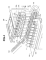
FIG. 4] FIG. 4 is a perspective view showing a cap supplying and gripping state of the cap fastening facility. - [
FIG. 5] FIG. 5 is a perspective view showing a cap gripping and forward moving state of the cap fastening facility. - [
FIG. 6] FIG. 6 is a perspective view showing a cap grip threadably attaching state of the cap fastening facility. - [
FIG. 7] FIG. 7 is a front elevational view showing a modified example of the cap fastening apparatus. - [
FIG. 8] FIG. 8 is a perspective view ofFIG. 7 . - A
cap fastening apparatus 10 is structured, as shown inFIG. 1 andFIG. 2 , such that a rotation of amotor 20 is transmitted to achuck 50 via atorque limiter apparatus 30 and aspeed reducer 40, and a cap 1 can be threadably attached to abottle 2 by a set torque. In this case, thecap fastening apparatus 10 can drive the cap 1 to thebottle 2. - In other words, the
cap fastening apparatus 10 supports themotor 20, thetorque limiter apparatus 30 and the speed reducer 40 in a supportingplate 11 which is supported to a stand (which is not illustrated inFIG. 1 andFIG. 2 ) so as to be movable in a back and forth direction and an up and down direction. In thecap fastening apparatus 10, a rotation of themotor 20 is decelerated by thespeed reducer 40 so as to be transmitted to thechuck 50. On the basis of the transmitted rotation, the cap 1 which is gripped by thechuck 50 is threadably attached to thebottle 2. Further, when a rotational resistance of thechuck 50 becomes larger than a set torque, thetorque limiter apparatus 30 which is interposed between themotor 20 and the speed reducer 40 and disconnects a transmission of the rotation from themotor 20 to thechuck 50 is actuated and the transmission is disconnected, whereby the cap 1 can be threadably attached to thebottle 2. - As the
motor 20, there is employed anormal motor 20, for example, an inverter motor in which a speed can be set, however, there can be employed a motor in which a precise control can be carried out in a speed, an acceleration, a deceleration or the like of a servo motor, a stepping motor or the like. Avertical bevel gear 21A which is provided in a rotating shaft of themotor 20 is engaged with atransverse bevel gear 21B which is provided in an input shaft of thetorque limiter apparatus 30, thereby transmitting the rotation of themotor 20 to thetorque limiter apparatus 30 and changing the rotation in a horizontal direction of the rotating shaft of themotor 20 into a vertical direction which is in parallel to a center axis of thechuck 50. Acase 22 of themotor 20 is fixed and supported to the supportingplate 11. - The
torque limiter apparatus 30 is not particularly limited in its type. As one example, there can be employed a pneumatic type which can connect and disconnect the transmission of the set torque on the basis of a dynamic friction force between opposite friction discs. As another example, thetorque limiter apparatus 30 can employ a magnet type which can connect and disconnect the transmission of the set torque on the basis of a magnetic force between opposite magnets. The pneumatic typetorque limiter apparatus 30 is structured such that the opposite friction discs generate a friction powder, however, is inexpensive. The magnet typetorque limiter apparatus 30 is structured such that the opposite magnets are not in contact with each other, and is semipermanently in maintenance free. Acase 31 of thetorque limiter apparatus 30 is fixed and supported to the supportingplate 11. - The
speed reducer 40 can be constructed by an intermeshing gear train of asmall gear 41 and alarge gear 42. The rotation of themotor 20 is decelerated by a reduction gear ratio R (1/3 in the present embodiment) which is constructed by a gear ratio (1:3 in the present embodiment) of thesmall gear 41 and thelarger gear 42, and is transmitted to thechuck 50. An aspect of thespeed reducer 40 is not limited to a combination of spur gears such as the present embodiment, but can be optionally selected, for example, a speed reducer constructed by gears in accordance with the other aspect, a combination of a belt and a pulley and the like. The reduction gear ratio R is preferably set to be about equal to or more than 1/2 and equal to or less than 1/10. If a degree of the reduction gear ratio is too small (a value of a denominator is small and a value of a denominator is close to 1), it becomes hard to downsize the capacity of thetorque limiter apparatus 30 which is an effect of the present invention. If the reduction gear ratio is too large (the value of the denominator is large), it is necessary to rotate themotor 20 at a high speed, and an expensive special motor is needed. Adrive shaft 43 is fixed to aboss 41A of thesmall gear 41, an output shaft of thetorque limiter apparatus 30 is connected to thedrive shaft 43, and a bearinghousing 43A pivotally supporting thedrive shaft 43 is fixed and supported to the supportingplate 11. A bearinghousing 44A pivotally supporting aboss 42A of thelarge gear 42 is fixed and supported to the supportingplate 11. A drivenshaft 45 is constructed by a spline shaft, and theboss 42A is a spline shaft receiver. In particular, a ball spline is preferable since it has a high precision and a high rigidity. In other words, theboss 42A is provided with the drivenshaft 45 which is connected in such a manner as to be integral in a rotating direction and be movable in an axial direction. It is preferable that an axis of the drivenshaft 45 is deviated from an axis of thedrive shaft 43 of thespeed reducer 40 without coming into line with it, and they are in parallel to each other. In particular, it is preferable that the drivenshaft 45 and thedrive shaft 43 of thespeed reducer 40 are arranged in parallel. - The
chuck 50 is structured such that various chuck heads 52 which are used by being replaced in correspondence to a dimension and a shape of the cap 1 can be attached to and detached from acoupler 51 which is fixed to a lower end portion of the drivenshaft 45 of thespeed reducer 40. Thechuck 50 supports aslide 54 to a vertical direction guiderod 53 which is fixed to the supportingplate 11 so as to be movable up and down, makes the drivenshaft 45 pass through an inner periphery of apneumatic manifold 55 which is provided in theslide 54 so as to be integrally and relatively rotatable in an axial direction, feeds a compressed air which is supplied from anair intake port 55A of thepneumatic manifold 55 to thechuck head 52 via a hollow portion of the drivenshaft 45, and opens and closes thechuck head 52 on the basis of a pneumatic force so as to grip the cap 1. An axis of thechuck 50 comes into line with an axis of the drivenshaft 45. In other words, it is preferable that the axis of thechuck 50 is deviated from the axis of thedrive shaft 43 of thespeed reducer 40 without coming into line with it, and they are in parallel to each other. - The driven
shaft 45 is provided in such a manner as to be movable in an axial direction with respect to thelarge gear 42 which is supported to the supportingplate 11. In accordance with this, in a standby state of thecap fastening apparatus 10, thechuck 50 and the drivenshaft 45 positions apositioning stopper 48 which is provided below thepneumatic manifold 55 locked to the drivenshaft 45 in the axial direction, at a lowest position which comes into contact with an upper surface of thelarge gear 42, on the basis of a gravitational force acting on thechuck 50. Thepositioning stopper 48 is fixed to an appropriate position of the drivenshaft 45. Further, an upper end portion of the drivenshaft 45 protrudes to an upper portion of thepneumatic manifold 55 so as to form animpact blow portion 45A. A cap driving apparatus which is not illustrated is arranged above theimpact blow portion 45A of the drivenshaft 45. The cap driving apparatus is driven by an air cylinder, a motor-driven cylinder or the like, and the cap driving apparatus has a driving head which drives theimpact blow portion 45A. - In accordance with the structure mentioned above, in the
cap fastening apparatus 10, thetorque limiter apparatus 30 is arranged on the axis of thedrive shaft 43 of thespeed reducer 40, and thechuck 50 is arranged on the axis of the drivenshaft 45 which is in parallel to thedrive shaft 43 of thespeed reducer 40, whereby the screw cap 1 which is gripped to thechuck head 52 of thechuck 50 can be threadably attached to an opening portion of thebottle 2 by a fixed torque on the basis of the rotation of themotor 20. The supportingplate 11 comes down in such a manner as to attach the cap 1 gripped by thechuck head 52 of thechuck 50 to the above of the opening portion of thebottle 2, at a time of threadably attaching the cap 1 by themotor 20. As a result, the drivenshaft 45 which is at the lowest position with respect to thelarge gear 42 of thespeed reducer 40 moves up with respect to thelarge gear 42. Accordingly, a downward movement at a screw pitch of the cap 1 at a time when thechuck head 52 is subsequently rotated by themotor 20 so as to threadably attach the cap 1 to the opening portion of thebottle 2 is allowed within a range of a distance of the upward movement mentioned above with respect to thelarge gear 42 of the drivenshaft 45. In this case,FIG. 1 andFIG. 2 show a state in which the drivengear 45 approximately moves up to an upper limit with respect to thelarge gear 42. An upper limit position at a time of moving upward is a position at which an upper portion of thecoupler 51 which is larger than an outer diameter of the drivenshaft 45 comes into contact with theboss 42A. - At this time, it is preferable that the
motor 20 has a clutch type brake (the clutch type brake may be embedded in themotor 20, or may be attached to the rotating shaft of the motor 20). The rotation of themotor 20 can be immediately transmitted to thetorque limiter apparatus 30, thespeed reducer 40 and thechuck 50 sequentially by releasing the clutch type brake of themotor 20 at a time of starting the threadable attachment of the cap 1 by themotor 20. If the threadably attaching work of the cap 1 by themotor 20 is finished by an actuation of thetorque limiter apparatus 30 at the limited torque, a change of a rotating condition, for example, a rotation deceleration or a rotation stop of arotating dog 46 provided in thedrive shaft 43 of thespeed reducer 40 is read by asensor 47 which is provided around thedog 46, and a control apparatus which is not illustrated disconnects in a moment the transmission of the rotation of themotor 20 by the clutch type brake of themotor 20, in accordance with the change of the rotating condition which is ready by thesensor 47, immediately releases the grip of the cap 1 by thechuck 50, and can finish the capping work by thecap fastening apparatus 10. On the basis of the structure mentioned above, it is possible to minimize the capping work time by thecap fastening apparatus 10 so as to improve a productivity. A control of a fastening torque of the cap 1 by thecap fastening apparatus 10 is carried out by thetorque limiter apparatus 30, and the clutch of themotor 20 does not take part in the control of the fastening torque of the cap 1. Further, using a motor which can carry out a rapid acceleration and a rapid deceleration of the servo motor, the stepping motor or the like, in place of use of themotor 20 having the clutch type brake, it is possible to immediately transmit the rotation of themotor 20 to thetorque limiter apparatus 30, thespeed reducer 40 and thechuck 50 sequentially, at a time of starting the threadable attachment as mentioned above. At a time of finishing the threadable attachment, it is possible to stop the rotation of themotor 20 in a moment, to immediately release the grip of the cap 1 by thechuck 50, and to finish the capping work by thecap fastening apparatus 10. - Accordingly, in the present invention, the term "clutch" indicates a structure which disconnects a rotating motion from an input shaft to an output shaft and a torque transmission on the basis of a control signal or any operation from an external portion. In this case, a means for preventing a torque beyond a set value of the input shaft from being transmitted to the output shaft is constructed by the torque limiter apparatus.
- Further, in the
cap fastening apparatus 10, the drivenshaft 45 is provided in such a manner as to be movable in the axial direction with respect to thelarge gear 42 of thespeed reducer 40, and the drive cap 1 can be driven to the opening portion of thebottle 2 by a drive head (not illustrated) which is provided in a lower end portion of the drivenshaft 45, on the basis of a movement in the axial direction of the drivenshaft 45. At a time of driving the cap 1, the drive head which is provided in the lower end portion of the drivenshaft 45 of thespeed reducer 40 locates at a position which corresponds to an appropriate driving operation position with respect to the opening portion of thebottle 2, on the basis of the rotation of the drivenshaft 45, and the drive head and the cap 1 are mounted on the opening portion of thebottle 2, on the basis of a downward movement of the supportingplate 11. As a result, the drivenshaft 45 existing at the lowest position with respect to thelarge gear 42 of thespeed reducer 40 moves up with respect to thelarge gear 42. Accordingly, the downward movement of the cap 1 at a time when the cap driving apparatus which is not illustrated subsequently drives theimpact blow portion 45A in the upper end portion of the drivenshaft 45 so as to drive the cap 1 to the opening portion of thebottle 2 is allowed within the range of the amount of the upward movement mentioned above with respect to thelarge gear 42 of the drivenshaft 45. - A description will be given of a
cap fastening facility 100 which employs thecap fastening device 10. Thecap fastening facility 100 is structured, as shown inFIG. 3 , such that astand 101 is provided with acap supplying chute 102, thecap supplying chute 102 is provided with a subsequent cap separating and supplyingconveyor 103, and the cap 1 which is supplied from thecap supplying chute 102 can be transferred to a plurality of cap separating and supplyingplates 104 which are arranged in a cap separating and supplying zone formed as one row on the cap separating and supplyingconveyor 103. - Further, the
cap fastening facility 100 is provided with acontainer feeding conveyor 105 in a front surface of the cap separating and supplyingconveyor 103, and can feed while accommodating thebottle 2 in each of the plurality ofcontainer feeding skirts 106 which are formed as one row on thecontainer feeding conveyor 105 and are arranged in a cap fastening zone. The cap separating and supplyingplates 104 are arranged in the cap separating and supplying zone on the cap separating and supplyingconveyor 103, theskirts 106 are arranged in the cap fastening zone on thecontainer feeding conveyor 105, and each of the cap separating and supplyingplates 104 and each of theskirts 106 correspond to each other in one-to-one relationship. - The
cap fastening facility 100 is provided in thestand 101 with the supportingplate 11 which can move in a back and forth direction by aservo motor 107 for a forward and backward movement and can move in an up and down direction by a servo motor for an upward and downward movement (not illustrated). Thecap fastening facility 100 is structured such that each of thecap fastening apparatuses 10 mentioned above is installed at each of positions on the supportingplate 11 respectively corresponding to the plurality of cap separating and supplyingplates 104 which are arranged in one row on the cap separating and supplyingconveyor 103 and stay in the cap separating and supplying zone, and the plurality ofskirts 106 which are arranged in one row on thecontainer feeding conveyor 105 and stay in the cap fastening zone. Thecap fastening facility 100 is provided in one side of the supportingplate 11 with a timingpulley 20 which is driven via a timing belt by one motor (not illustrated), and a longrotating shaft 20A which is driven by the timingpulley 20 driven by the motor (not illustrated) extends along the cap separating and supplyingconveyor 103 of the supportingplate 11 and thecontainer feeding conveyor 105. Further, thevertical bevel gear 21A of thecap fastening apparatus 10 is provided at each of the positions in the axial direction of therotating shaft 20A, and thetransverse bevel gear 21B engaging with thevertical bevel gear 21A, thetorque limiter apparatus 30, thespeed reducer 40 and thechuck 50 are provided in the same as shown inFIG. 1 andFIG. 2 . - Accordingly, a cap fastening motion by the
cap fastening facility 100 is carried out as shown below (FIG. 4 to FIG. 6 ). - (A) Cap supplying and gripping step (
FIG. 4 ) - (1) The cap 1 is supplied to the
cap supplying chute 102. - (2) The cap separating and supplying
conveyor 103 rotates, and the cap 1 of thecap supplying chute 102 is supplied to the cap separating and supplyingplate 104 of the cap separating and supplyingconveyor 103. - (3) When the cap 1 is supplied to all the cap separating and supplying
plates 104 in the cap separating and supplying zone which form one row on the cap separating and supplyingconveyor 103, the supportingplate 11 comes down by the servo motor for the upward and downward movement, and the cap 1 in each of the cap separating and supplyingplates 104 is gripped by thechuck head 52 of thechuck 50 in each of thecap fastening apparatuses 10. - (B) Cap gripping and forward moving step (
FIG. 5 ) - (1) The supporting
plate 11 is moved up by the servo motor for the upward and downward movement. - (2) The supporting
plate 11 is moved forward by theservo motor 107 for the forward and backward movement, and the cap 1 which thechuck head 52 of thechuck 50 in each of thecap fastening apparatuses 10 grips is positioned in the upper portion of thebottle 2 which is accommodated in each of theskirts 106 on thecontainer feeding conveyor 105. - (3) The cap separating and supplying
conveyor 103 rotates, and supplies the cap 1 in thecap supplying chute 102 to the cap separating and supplyingplate 104 of the cap separating and supplyingconveyor 103. - (C) Cap gripping and fastening step (
FIG. 6 ) - (1) The supporting
plate 11 is moved down by the servo motor for the upward and downward movement, and the cap 1 which thechuck head 52 of thechuck 50 in each of thecap fastening apparatuses 10 grips is pressed against the opening portion of thebottle 2 which is accommodated in each of theskirts 106 on thecontainer feeding conveyor 105. - (2) The
chuck head 52 of thechuck 50 is rotated by the timingpulley 20 which is driven by the motor (not illustrated) of each of thecap fastening apparatuses 10, and the cap 1 is threadably attached to the opening portion of thebottle 2 by the set torque which is determined by thetorque limiter apparatus 30. The end of the threadable attachment of the cap 1 is detected by thesensor 47 mentioned above, the transmission of the rotation of themotor 20 is disconnected in a moment by the clutch type brake of themotor 20, and the grip of the cap 1 by thechuck 50 is immediately released. - On the other hand, a drive cap 1 uses the drive head of the cap driving apparatus which is provided in the driven
shaft 45 of thespeed reducer 40 in each of thecap fastening apparatuses 10. The drive head drives theimpact blow portion 45A of the drivenshaft 45, and carries out the driving on the basis of the movement in the axial direction of the drivenshaft 45. - (3) The supporting
plate 11 is moved up by the servo motor for the upward and downward movement, the supportingplate 11 is subsequently moved backward by theservo motor 107 for the forward and backward movement, and each of thecap fastening apparatuses 10 is returned to the standby position on the cap separating and supplyingconveyor 103. - In accordance with the
cap fastening apparatus 10 of the present embodiment, the following operations and effects can be achieved. - (a) The
torque limiter apparatus 30 is interposed between themotor 20 and thespeed reducer 40, thetorque limiter apparatus 30 disconnecting the transmission of the rotation from themotor 20 to thechuck 50, at a time when the rotational resistance of thechuck 50 becomes larger than the set torque. The fastening torque of the cap 1 by thechuck 50 is limited by thetorque limiter apparatus 30 via thespeed reducer 40. On the assumption that the reduction gear ratio of thespeed reducer 40 is set to R (for example, 1/3), the limited torque by thetorque limiter apparatus 30 is reduced to R times the set torque mentioned above. Accordingly, it is possible to downsize the capacity of thetorque limiter apparatus 30 in comparison with the magnitude of the set torque of thecap fastening apparatus 10, that is, the capacity in the case that thetorque limiter apparatus 30 exists between the speed reducer and the chuck such as the prior art. In the case that the reduction gear ratio R is 1/3 as one example, it is possible to set the capacity of thetorque limiter apparatus 30 to 1/3. - In accordance with this, the weight of the
torque limiter apparatus 30 becomes small, and the whole weight of thecap fastening apparatus 10 in which thetorque limiter apparatus 30 is accessorily provided in thechuck 50 becomes small. As a result, the moving apparatus (theservo motor 107 for the forward and backward movement and the servo motor for the upward and downward movement) which moves thecap fastening apparatus 10 from the cap delivery position to the cap fastening position is downsized. - Further, the outside dimension of the
torque limiter apparatus 30 becomes smaller, and a total dimension of thecap fastening facility 100 is downsized, thecap fastening facility 100 being installed in parallel with the plural sets, each set being constructed by thetorque limiter apparatus 30, thespeed reducer 40 and thechuck 50, and being capable of fastening a plurality of caps 1 to a plurality ofbottles 2. - Further, the weight of the
torque limiter apparatus 30 becomes smaller, the moment of inertia thereof becomes smaller, the precision of the fastening torque of the cap 1 which is limited by thetorque limiter apparatus 30 is improved, and the value of the fastening torque which is applied to the cap 1 is stabilized. - (b) The cap driving apparatus driving the cap 1 to the
bottle 2 can be additionally provided in thecap fastening apparatus 10. Thetorque limiter apparatus 30 which is arranged on thedrive shaft 43 of thespeed reducer 40, and thechuck 50 which is arranged on the drivenshaft 45 of thespeed reducer 40 are arranged in parallel without bringing the axes into line with each other, that is, in the state in which the axes are deviated, and thetorque limiter apparatus 30 is not arranged on the center axis of thechuck 50. Accordingly, even if the cap driving apparatus is arranged above the center axis of thechuck 50, the impact blow which the cap driving apparatus applies to thechuck 50 does not directly act on thetorque limiter apparatus 30 to damage it. The cap driving apparatus can be easily provided additionally in thecap fastening apparatus 10. - A
cap fastening apparatus 110 shown inFIG. 7 andFIG. 8 is constructed by aservo motor 120, a torque limiter apparatus 130 (FIG. 7 ), thespeed reducer 40 and thechuck 50. A different point of thecap fastening apparatus 110 from thecap fastening apparatus 10 mentioned above exists in a point that the set of themotor 20 and thetorque limiter apparatus 30 mentioned above is replaced with the servo motor 120 (the torque limiter apparatus 130). An output shaft of theservo motor 120 is connected to thedrive shaft 43 of thespeed reducer 40 via acoupling 121. In other words, a servo amplifier additionally provided in theservo motor 120 is used as thetorque limiter apparatus 130, a current value which theservo motor 120 rotating thechuck 50 consumes, that is, a magnitude of the torque is output from the servo amplifier, and in the case that an instantaneous torque data of theservo motor 120 obtained thereby becomes larger than the set torque of thechuck 50, or is expected to become larger, theservo motor 120 is stopped, and the transmission of the rotation from theservo motor 120 to thechuck 50 is disconnected. - In accordance with the
cap fastening apparatus 110, thetorque limiter apparatus 130 constructed by theservo motor 120 is interposed between theservo motor 120 and thespeed reducer 40, and it is possible to set the servo motor 120 (the torque limiter apparatus 130) to the low torque type and employ theservo motor 120 which is compact and light in weight, in the same manner as thetorque limiter apparatus 30 of thecap fastening apparatus 10. Further, the motor type is not limited to the servo motor, but can employ in the same manner a motor in which a magnitude of a torque can be output. - In this case, a pair of vertical and transverse bevel gear trains can be interposed in a connection portion between the output shaft of the
servo motor 120 and thedrive shaft 43 of thespeed reducer 40, and the output shaft of theservo motor 120 can be arranged in a horizontal direction which is orthogonal to the center axis of thechuck 50. - In accordance with the present invention, in the cap fastening apparatus in which the cap is threadably attached to the bottle by the chuck rotated by the motor, it is possible to downsize the capacity of the torque limiter apparatus limiting the set torque which is necessary for fastening the cap by the chuck. Further, in accordance with the present invention, the cap driving apparatus can be easily provided additionally in the cap fastening apparatus.
-
- 1
- cap
- 2
- bottle
- 10
- cap fastening apparatus
- 20
- motor
- 30
- torque limiter apparatus
- 40
- speed reducer
- 43
- drive shaft
- 45
- driven shaft
- 50
- chuck
- 100
- cap fastening facility
- 110
- cap fastening apparatus
- 120
- servo motor
- 130
- torque limiter apparatus
Claims (7)
- A cap fastening apparatus in which a rotation of a motor is transmitted to a chuck while being decelerated by a speed reducer, and a cap gripped by the chuck is threadably attached to a bottle,
wherein a torque limiter apparatus is interposed between the motor and the speed reducer, the torque limiter apparatus disconnecting a transmission of a rotation from the motor to the chuck at a time when a rotational resistance of the chuck becomes larger than a set torque. - The cap fastening apparatus according to claim 1, wherein the torque limiter apparatus is arranged on a drive shaft of the speed reducer, and an axis of the chuck does not come into line with an axis of a drive shaft of the speed reducer.
- The cap fastening apparatus according to claim 2, wherein the axis of the chuck is arranged on a driven shaft which is in parallel to the drive shaft of the speed reducer.
- The cap fastening apparatus according to claim 2 or 3, wherein the driven shaft is provided in such a manner as to be movable in an axial direction with respect to the speed reducer.
- The cap fastening apparatus according to claim 4, wherein a cap driving apparatus is provided above the driven shaft, and the cap is capable of being driven to the bottle on the basis of a movement in an axial direction of the driven shaft.
- The cap fastening apparatus according to any of claims 1 to 5, wherein a rotation of the motor is transmitted to a plurality of chucks via plural sets of the torque limiter apparatuses and the speed reducers.
- The cap fastening apparatus according to any of claims 1 to 6, wherein a reduction gear ratio of the speed reducer is set to be equal to or more than 1/2 and equal to or less than 1/10.
Applications Claiming Priority (2)
| Application Number | Priority Date | Filing Date | Title |
|---|---|---|---|
| JP2010036570A JP5383546B2 (en) | 2010-02-22 | 2010-02-22 | Cap tightening device |
| PCT/JP2011/053380 WO2011102417A1 (en) | 2010-02-22 | 2011-02-17 | Cap fastening device |
Publications (3)
| Publication Number | Publication Date |
|---|---|
| EP2540658A1 true EP2540658A1 (en) | 2013-01-02 |
| EP2540658A4 EP2540658A4 (en) | 2015-12-09 |
| EP2540658B1 EP2540658B1 (en) | 2017-08-23 |
Family
ID=44483003
Family Applications (1)
| Application Number | Title | Priority Date | Filing Date |
|---|---|---|---|
| EP11744703.7A Not-in-force EP2540658B1 (en) | 2010-02-22 | 2011-02-17 | Cap fastening device |
Country Status (5)
| Country | Link |
|---|---|
| US (1) | US20120311963A1 (en) |
| EP (1) | EP2540658B1 (en) |
| JP (1) | JP5383546B2 (en) |
| CN (1) | CN102770366B (en) |
| WO (1) | WO2011102417A1 (en) |
Cited By (9)
| Publication number | Priority date | Publication date | Assignee | Title |
|---|---|---|---|---|
| CN104030209A (en) * | 2014-05-21 | 2014-09-10 | 成都中牧生物药业有限公司 | Bottle aluminum foil cap mounting packaging equipment |
| CN104030206A (en) * | 2014-05-21 | 2014-09-10 | 成都中牧生物药业有限公司 | Medicine bottle cap packaging device |
| CN104030210A (en) * | 2014-05-21 | 2014-09-10 | 成都中牧生物药业有限公司 | Bottle mouth aluminum foil cover clamping mechanism |
| EP3153413A1 (en) * | 2015-10-05 | 2017-04-12 | Tetra Laval Holdings & Finance S.A. | A method of, and an applying head for, applying a lid onto a container |
| EP3153414A1 (en) * | 2015-10-05 | 2017-04-12 | Tetra Laval Holdings & Finance S.A. | An applying unit for applying a lid onto a container |
| EP3153415A1 (en) * | 2015-10-05 | 2017-04-12 | Tetra Laval Holdings & Finance S.A. | An apparatus for capping a container |
| WO2017204612A1 (en) * | 2016-05-27 | 2017-11-30 | Pack System S.A. De C.V. | Linear capping system having multiple independent traction heads |
| EP3656684A1 (en) * | 2018-11-23 | 2020-05-27 | Tetra Laval Holdings & Finance S.A. | Capping apparatus for a system for production of packaged food products |
| IT202300006198A1 (en) * | 2023-03-30 | 2024-09-30 | Tetra Laval Holdings & Finance | CAPPING APPARATUS FOR A PACKAGING MACHINE AND PACKAGING MACHINE HAVING A CAPPING APPARATUS |
Families Citing this family (25)
| Publication number | Priority date | Publication date | Assignee | Title |
|---|---|---|---|---|
| CN103075637A (en) * | 2013-02-08 | 2013-05-01 | 上海鲁诗瓦格环保技术有限公司 | Constant-force emergency closing system for cylinder valve |
| US9095945B2 (en) | 2013-05-14 | 2015-08-04 | Honda Motor Co., Ltd. | Automated steering centering assembly |
| EP2871031B1 (en) * | 2013-10-18 | 2018-04-25 | Pall Life Sciences Belgium BVBA | Disposable production line for filling and finishing a product |
| EP2886508B1 (en) * | 2013-12-20 | 2016-04-13 | CTC Analytics AG | Actuating device for screw-on cap |
| EP2927132B1 (en) * | 2014-04-04 | 2016-09-14 | Tetra Laval Holdings & Finance S.A. | Unit for the application of lids of opening devices |
| US10800565B1 (en) * | 2014-05-07 | 2020-10-13 | Express Scripts Strategic Development, Inc. | Systems and methods for capping |
| CN105333199A (en) * | 2015-11-06 | 2016-02-17 | 江门市宏乔新材料科技有限公司江海区分公司 | Gas bottle closing valve |
| CN105366609A (en) * | 2015-11-17 | 2016-03-02 | 长春北方化工灌装设备有限公司 | Control method for closing capping machine with torque perceptive function |
| CN105565230A (en) * | 2016-02-06 | 2016-05-11 | 常州汇拓科技有限公司 | Cap screwing mechanism |
| US10351405B2 (en) * | 2016-02-11 | 2019-07-16 | NJM Packaging Inc. | Capping machine |
| DE102018221034A1 (en) * | 2018-12-05 | 2020-06-10 | Krones Ag | DEVICE AND METHOD FOR CLOSING A BOTTLE WITH TORQUE MEASUREMENT |
| IT201900020730A1 (en) * | 2019-11-11 | 2021-05-11 | Kuma S R L | CAPPING MACHINE |
| JP7400390B2 (en) * | 2019-11-22 | 2023-12-19 | アルテミラ製缶株式会社 | Tabletop capping device |
| CN111232901A (en) * | 2020-03-14 | 2020-06-05 | 长沙迈迪克智能科技有限公司 | Automatic cap opening machine for test tube |
| CN112125254A (en) * | 2020-09-11 | 2020-12-25 | 广州雪霸专用设备有限公司 | Single-head servo cap screwing machine |
| CN112225149A (en) * | 2020-10-16 | 2021-01-15 | 浙江大学昆山创新中心 | Cap screwing device mechanism |
| CN112093745B (en) * | 2020-11-11 | 2025-01-28 | 无锡米多智能技术有限公司 | Iron cap screwing device |
| CN113735034A (en) * | 2021-09-09 | 2021-12-03 | 苏州通产丽星包装科技有限公司 | But real-time torsion control's upper cover device |
| CN114011733B (en) * | 2021-10-29 | 2024-05-24 | 苏州英诺威视半导体设备有限公司 | Glass disc protection system and glass disc protection method |
| JP7797836B2 (en) * | 2021-11-15 | 2026-01-14 | 株式会社島津製作所 | Capping and pre-treatment device |
| IT202200002780A1 (en) * | 2022-02-15 | 2023-08-15 | Arol Spa | Roto-translating capping head with static drive unit |
| CN114572919B (en) * | 2022-02-24 | 2024-10-18 | 广东同地科技有限公司 | Tightening mechanism and control method thereof |
| CN114537876A (en) * | 2022-03-22 | 2022-05-27 | 基点生物科技(上海)有限公司 | Freeze and deposit pipe tube lid and structure of uncapping |
| US20240300795A1 (en) * | 2023-03-07 | 2024-09-12 | Opio Connect, Inc. | Cap attachment system |
| US20250376366A1 (en) * | 2024-06-07 | 2025-12-11 | Psr Automation, Inc. | Container top closure apparatus, automation system and related methods |
Family Cites Families (19)
| Publication number | Priority date | Publication date | Assignee | Title |
|---|---|---|---|---|
| US1614042A (en) * | 1920-01-13 | 1927-01-11 | Standard Automatic Machine Com | Container-capping machine |
| US2005186A (en) * | 1933-12-30 | 1935-06-18 | Owens Hlinois Glass Company | Apparatus for tightening caps on jars |
| US2655302A (en) * | 1949-12-19 | 1953-10-13 | Owens Illinois Glass Co | Machine for applying screw caps to containers |
| FR2644094A1 (en) * | 1989-03-10 | 1990-09-14 | Bertaud A Ets | TIGHTENING DEVICE WITH ADJUSTABLE TIGHTENING TORQUE |
| JPH03117699U (en) * | 1990-03-19 | 1991-12-05 | ||
| GB9306521D0 (en) * | 1993-03-29 | 1993-05-19 | Gei Filling Capping And Labell | A capping machine |
| US5417031A (en) * | 1993-08-26 | 1995-05-23 | New England Machinery, Inc. | Apparatus for rotating cylindrical caps onto containers |
| FR2724430B1 (en) * | 1994-09-09 | 1996-11-22 | Serac Sa | TORQUE LIMITATION TRANSMISSION DEVICE |
| JP2740856B2 (en) * | 1996-04-03 | 1998-04-15 | 花王株式会社 | Container capping method and apparatus |
| JP4108794B2 (en) * | 1997-08-22 | 2008-06-25 | 株式会社日本製鋼所 | Bolt attachment / detachment device |
| US6105343A (en) * | 1998-11-06 | 2000-08-22 | Pneumatic Scale Corporation | Apparatus and method for a capping machine |
| JP2000264395A (en) * | 1999-03-18 | 2000-09-26 | Sekisui Plant Systems Co Ltd | Cap tightening device |
| JP4332929B2 (en) * | 1999-04-07 | 2009-09-16 | 澁谷工業株式会社 | Resin bottle transport device |
| JP2004123109A (en) * | 2002-09-30 | 2004-04-22 | Kuroisutaa Chemicals:Kk | Cap tightening method and apparatus therefor |
| JP4436147B2 (en) * | 2004-02-04 | 2010-03-24 | 日本電産サンキョー株式会社 | Toilet seat lifting device |
| JP2006240738A (en) * | 2005-02-07 | 2006-09-14 | Yuyama Manufacturing Co Ltd | Vial capping device and vial capping method |
| FR2885896B1 (en) * | 2005-05-19 | 2007-07-27 | Serac Group Soc Par Actions Si | MAGNETIC CLUTCH CAPS SCREWING DEVICE |
| JP4454674B2 (en) * | 2007-08-09 | 2010-04-21 | 本田技研工業株式会社 | Screw tightening device |
| CN101386399A (en) * | 2008-10-09 | 2009-03-18 | 上海交通大学 | Servo bottle cap tightening mechanism |
-
2010
- 2010-02-22 JP JP2010036570A patent/JP5383546B2/en active Active
-
2011
- 2011-02-17 WO PCT/JP2011/053380 patent/WO2011102417A1/en not_active Ceased
- 2011-02-17 US US13/578,958 patent/US20120311963A1/en not_active Abandoned
- 2011-02-17 EP EP11744703.7A patent/EP2540658B1/en not_active Not-in-force
- 2011-02-17 CN CN201180010488.0A patent/CN102770366B/en not_active Expired - Fee Related
Non-Patent Citations (1)
| Title |
|---|
| See references of WO2011102417A1 * |
Cited By (21)
| Publication number | Priority date | Publication date | Assignee | Title |
|---|---|---|---|---|
| CN104030209A (en) * | 2014-05-21 | 2014-09-10 | 成都中牧生物药业有限公司 | Bottle aluminum foil cap mounting packaging equipment |
| CN104030206A (en) * | 2014-05-21 | 2014-09-10 | 成都中牧生物药业有限公司 | Medicine bottle cap packaging device |
| CN104030210A (en) * | 2014-05-21 | 2014-09-10 | 成都中牧生物药业有限公司 | Bottle mouth aluminum foil cover clamping mechanism |
| CN104030209B (en) * | 2014-05-21 | 2016-01-20 | 成都中牧生物药业有限公司 | A kind of ampulla aluminum foil cover packaging facilities |
| CN104030206B (en) * | 2014-05-21 | 2016-01-20 | 成都中牧生物药业有限公司 | Cap of medicine bottle packing device |
| WO2017060060A1 (en) * | 2015-10-05 | 2017-04-13 | Tetra Laval Holdings & Finance S.A. | A method of, and an applying head for, applying a lid onto a container |
| CN107922061A (en) * | 2015-10-05 | 2018-04-17 | 利乐拉瓦尔集团及财务有限公司 | A kind of equipment for covered container |
| EP3153415A1 (en) * | 2015-10-05 | 2017-04-12 | Tetra Laval Holdings & Finance S.A. | An apparatus for capping a container |
| WO2017060058A1 (en) * | 2015-10-05 | 2017-04-13 | Tetra Laval Holdings & Finance S.A. | An applying unit for applying a lid onto a container |
| WO2017060059A1 (en) * | 2015-10-05 | 2017-04-13 | Tetra Laval Holdings & Finance S.A. | An apparatus for capping a container |
| EP3153413A1 (en) * | 2015-10-05 | 2017-04-12 | Tetra Laval Holdings & Finance S.A. | A method of, and an applying head for, applying a lid onto a container |
| US10967996B2 (en) | 2015-10-05 | 2021-04-06 | Tetra Laval Holdings & Finance S.A. | Method of, and an applying head for, applying a lid onto a container |
| EP3153414A1 (en) * | 2015-10-05 | 2017-04-12 | Tetra Laval Holdings & Finance S.A. | An applying unit for applying a lid onto a container |
| CN107922061B (en) * | 2015-10-05 | 2019-04-02 | 利乐拉瓦尔集团及财务有限公司 | A device for capping containers |
| US10351286B2 (en) | 2015-10-05 | 2019-07-16 | Tetra Laval Holdings & Finance S.A. | Applying unit for applying a lid onto a container |
| US10815017B2 (en) | 2015-10-05 | 2020-10-27 | Tetra Laval Holdings & Finance S.A. | Apparatus for capping a container |
| WO2017204612A1 (en) * | 2016-05-27 | 2017-11-30 | Pack System S.A. De C.V. | Linear capping system having multiple independent traction heads |
| EP3656684A1 (en) * | 2018-11-23 | 2020-05-27 | Tetra Laval Holdings & Finance S.A. | Capping apparatus for a system for production of packaged food products |
| IT202300006198A1 (en) * | 2023-03-30 | 2024-09-30 | Tetra Laval Holdings & Finance | CAPPING APPARATUS FOR A PACKAGING MACHINE AND PACKAGING MACHINE HAVING A CAPPING APPARATUS |
| WO2024200345A1 (en) * | 2023-03-30 | 2024-10-03 | Tetra Laval Holdings & Finance S.A. | Capping apparatus for a packaging machine and packaging machine having a capping apparatus |
| EP4455025A1 (en) * | 2023-03-30 | 2024-10-30 | Tetra Laval Holdings & Finance S.A. | Capping apparatus for a packaging machine and packaging machine having a capping apparatus |
Also Published As
| Publication number | Publication date |
|---|---|
| CN102770366B (en) | 2015-09-16 |
| CN102770366A (en) | 2012-11-07 |
| US20120311963A1 (en) | 2012-12-13 |
| JP2011168332A (en) | 2011-09-01 |
| JP5383546B2 (en) | 2014-01-08 |
| WO2011102417A1 (en) | 2011-08-25 |
| EP2540658A4 (en) | 2015-12-09 |
| EP2540658B1 (en) | 2017-08-23 |
Similar Documents
| Publication | Publication Date | Title |
|---|---|---|
| EP2540658B1 (en) | Cap fastening device | |
| US12172249B2 (en) | Carbide blade cutter head filling device and method | |
| US9061419B2 (en) | Processing tool and processing method | |
| US8656688B2 (en) | Capper | |
| EP2377630B1 (en) | Workpiece transfer apparatus for press machine and crossbar unit | |
| EP2246224A3 (en) | Webbing Take-up Device | |
| US20150074964A1 (en) | Blind rivet fastening device | |
| US20150175289A1 (en) | Activating device for screw caps | |
| CN208007462U (en) | A kind of body rotational structure | |
| EP2855046A1 (en) | Blind rivet fastening device | |
| EP2985114A2 (en) | Workpiece conveying device and machine tool | |
| CN106945067A (en) | A kind of manipulator quick change clamping jaw device | |
| JP2007237346A (en) | Conveying robot arm | |
| CN107511844A (en) | A kind of modularization aero tyre grabbing device | |
| CN203804974U (en) | Horizontal-joint robot | |
| CN219296562U (en) | Rotatory clamping jaw of intelligence | |
| CN213707000U (en) | Disc spring loading attachment | |
| CN101786124A (en) | Shutting and centering mechanism produced by manipulator punching automation | |
| CN102489825A (en) | Lifting device for high-accuracy numerically-controlled cutting machine | |
| CN209778256U (en) | Speed-following cap screwing machine | |
| EP3546083B1 (en) | Plate material feeding device | |
| CN215155900U (en) | Twist caps and hose caps | |
| SE529735C2 (en) | Method and apparatus for transmitting rotational motion | |
| EP4299489A1 (en) | Flow control device for a conveyor system | |
| CN221498593U (en) | Material conveying equipment |
Legal Events
| Date | Code | Title | Description |
|---|---|---|---|
| PUAI | Public reference made under article 153(3) epc to a published international application that has entered the european phase |
Free format text: ORIGINAL CODE: 0009012 |
|
| 17P | Request for examination filed |
Effective date: 20120802 |
|
| AK | Designated contracting states |
Kind code of ref document: A1 Designated state(s): AL AT BE BG CH CY CZ DE DK EE ES FI FR GB GR HR HU IE IS IT LI LT LU LV MC MK MT NL NO PL PT RO RS SE SI SK SM TR |
|
| DAX | Request for extension of the european patent (deleted) | ||
| RA4 | Supplementary search report drawn up and despatched (corrected) |
Effective date: 20151106 |
|
| RIC1 | Information provided on ipc code assigned before grant |
Ipc: B67B 3/20 20060101AFI20151102BHEP |
|
| 17Q | First examination report despatched |
Effective date: 20160708 |
|
| GRAP | Despatch of communication of intention to grant a patent |
Free format text: ORIGINAL CODE: EPIDOSNIGR1 |
|
| INTG | Intention to grant announced |
Effective date: 20170315 |
|
| GRAS | Grant fee paid |
Free format text: ORIGINAL CODE: EPIDOSNIGR3 |
|
| GRAA | (expected) grant |
Free format text: ORIGINAL CODE: 0009210 |
|
| AK | Designated contracting states |
Kind code of ref document: B1 Designated state(s): AL AT BE BG CH CY CZ DE DK EE ES FI FR GB GR HR HU IE IS IT LI LT LU LV MC MK MT NL NO PL PT RO RS SE SI SK SM TR |
|
| RAP1 | Party data changed (applicant data changed or rights of an application transferred) |
Owner name: KAO CORPORATION |
|
| REG | Reference to a national code |
Ref country code: GB Ref legal event code: FG4D |
|
| REG | Reference to a national code |
Ref country code: CH Ref legal event code: EP |
|
| REG | Reference to a national code |
Ref country code: AT Ref legal event code: REF Ref document number: 921111 Country of ref document: AT Kind code of ref document: T Effective date: 20170915 |
|
| REG | Reference to a national code |
Ref country code: IE Ref legal event code: FG4D |
|
| REG | Reference to a national code |
Ref country code: DE Ref legal event code: R096 Ref document number: 602011040874 Country of ref document: DE |
|
| REG | Reference to a national code |
Ref country code: NL Ref legal event code: MP Effective date: 20170823 |
|
| REG | Reference to a national code |
Ref country code: LT Ref legal event code: MG4D |
|
| REG | Reference to a national code |
Ref country code: FR Ref legal event code: PLFP Year of fee payment: 8 |
|
| REG | Reference to a national code |
Ref country code: AT Ref legal event code: MK05 Ref document number: 921111 Country of ref document: AT Kind code of ref document: T Effective date: 20170823 |
|
| PG25 | Lapsed in a contracting state [announced via postgrant information from national office to epo] |
Ref country code: NL Free format text: LAPSE BECAUSE OF FAILURE TO SUBMIT A TRANSLATION OF THE DESCRIPTION OR TO PAY THE FEE WITHIN THE PRESCRIBED TIME-LIMIT Effective date: 20170823 Ref country code: NO Free format text: LAPSE BECAUSE OF FAILURE TO SUBMIT A TRANSLATION OF THE DESCRIPTION OR TO PAY THE FEE WITHIN THE PRESCRIBED TIME-LIMIT Effective date: 20171123 Ref country code: HR Free format text: LAPSE BECAUSE OF FAILURE TO SUBMIT A TRANSLATION OF THE DESCRIPTION OR TO PAY THE FEE WITHIN THE PRESCRIBED TIME-LIMIT Effective date: 20170823 Ref country code: SE Free format text: LAPSE BECAUSE OF FAILURE TO SUBMIT A TRANSLATION OF THE DESCRIPTION OR TO PAY THE FEE WITHIN THE PRESCRIBED TIME-LIMIT Effective date: 20170823 Ref country code: AT Free format text: LAPSE BECAUSE OF FAILURE TO SUBMIT A TRANSLATION OF THE DESCRIPTION OR TO PAY THE FEE WITHIN THE PRESCRIBED TIME-LIMIT Effective date: 20170823 Ref country code: LT Free format text: LAPSE BECAUSE OF FAILURE TO SUBMIT A TRANSLATION OF THE DESCRIPTION OR TO PAY THE FEE WITHIN THE PRESCRIBED TIME-LIMIT Effective date: 20170823 Ref country code: FI Free format text: LAPSE BECAUSE OF FAILURE TO SUBMIT A TRANSLATION OF THE DESCRIPTION OR TO PAY THE FEE WITHIN THE PRESCRIBED TIME-LIMIT Effective date: 20170823 |
|
| PG25 | Lapsed in a contracting state [announced via postgrant information from national office to epo] |
Ref country code: RS Free format text: LAPSE BECAUSE OF FAILURE TO SUBMIT A TRANSLATION OF THE DESCRIPTION OR TO PAY THE FEE WITHIN THE PRESCRIBED TIME-LIMIT Effective date: 20170823 Ref country code: GR Free format text: LAPSE BECAUSE OF FAILURE TO SUBMIT A TRANSLATION OF THE DESCRIPTION OR TO PAY THE FEE WITHIN THE PRESCRIBED TIME-LIMIT Effective date: 20171124 Ref country code: ES Free format text: LAPSE BECAUSE OF FAILURE TO SUBMIT A TRANSLATION OF THE DESCRIPTION OR TO PAY THE FEE WITHIN THE PRESCRIBED TIME-LIMIT Effective date: 20170823 Ref country code: PL Free format text: LAPSE BECAUSE OF FAILURE TO SUBMIT A TRANSLATION OF THE DESCRIPTION OR TO PAY THE FEE WITHIN THE PRESCRIBED TIME-LIMIT Effective date: 20170823 Ref country code: LV Free format text: LAPSE BECAUSE OF FAILURE TO SUBMIT A TRANSLATION OF THE DESCRIPTION OR TO PAY THE FEE WITHIN THE PRESCRIBED TIME-LIMIT Effective date: 20170823 Ref country code: BG Free format text: LAPSE BECAUSE OF FAILURE TO SUBMIT A TRANSLATION OF THE DESCRIPTION OR TO PAY THE FEE WITHIN THE PRESCRIBED TIME-LIMIT Effective date: 20171123 Ref country code: IS Free format text: LAPSE BECAUSE OF FAILURE TO SUBMIT A TRANSLATION OF THE DESCRIPTION OR TO PAY THE FEE WITHIN THE PRESCRIBED TIME-LIMIT Effective date: 20171223 |
|
| PG25 | Lapsed in a contracting state [announced via postgrant information from national office to epo] |
Ref country code: CZ Free format text: LAPSE BECAUSE OF FAILURE TO SUBMIT A TRANSLATION OF THE DESCRIPTION OR TO PAY THE FEE WITHIN THE PRESCRIBED TIME-LIMIT Effective date: 20170823 Ref country code: DK Free format text: LAPSE BECAUSE OF FAILURE TO SUBMIT A TRANSLATION OF THE DESCRIPTION OR TO PAY THE FEE WITHIN THE PRESCRIBED TIME-LIMIT Effective date: 20170823 Ref country code: RO Free format text: LAPSE BECAUSE OF FAILURE TO SUBMIT A TRANSLATION OF THE DESCRIPTION OR TO PAY THE FEE WITHIN THE PRESCRIBED TIME-LIMIT Effective date: 20170823 |
|
| REG | Reference to a national code |
Ref country code: DE Ref legal event code: R097 Ref document number: 602011040874 Country of ref document: DE |
|
| PG25 | Lapsed in a contracting state [announced via postgrant information from national office to epo] |
Ref country code: EE Free format text: LAPSE BECAUSE OF FAILURE TO SUBMIT A TRANSLATION OF THE DESCRIPTION OR TO PAY THE FEE WITHIN THE PRESCRIBED TIME-LIMIT Effective date: 20170823 Ref country code: IT Free format text: LAPSE BECAUSE OF FAILURE TO SUBMIT A TRANSLATION OF THE DESCRIPTION OR TO PAY THE FEE WITHIN THE PRESCRIBED TIME-LIMIT Effective date: 20170823 Ref country code: SK Free format text: LAPSE BECAUSE OF FAILURE TO SUBMIT A TRANSLATION OF THE DESCRIPTION OR TO PAY THE FEE WITHIN THE PRESCRIBED TIME-LIMIT Effective date: 20170823 Ref country code: SM Free format text: LAPSE BECAUSE OF FAILURE TO SUBMIT A TRANSLATION OF THE DESCRIPTION OR TO PAY THE FEE WITHIN THE PRESCRIBED TIME-LIMIT Effective date: 20170823 |
|
| PLBE | No opposition filed within time limit |
Free format text: ORIGINAL CODE: 0009261 |
|
| STAA | Information on the status of an ep patent application or granted ep patent |
Free format text: STATUS: NO OPPOSITION FILED WITHIN TIME LIMIT |
|
| 26N | No opposition filed |
Effective date: 20180524 |
|
| PG25 | Lapsed in a contracting state [announced via postgrant information from national office to epo] |
Ref country code: SI Free format text: LAPSE BECAUSE OF FAILURE TO SUBMIT A TRANSLATION OF THE DESCRIPTION OR TO PAY THE FEE WITHIN THE PRESCRIBED TIME-LIMIT Effective date: 20170823 |
|
| REG | Reference to a national code |
Ref country code: CH Ref legal event code: PL |
|
| PG25 | Lapsed in a contracting state [announced via postgrant information from national office to epo] |
Ref country code: MC Free format text: LAPSE BECAUSE OF FAILURE TO SUBMIT A TRANSLATION OF THE DESCRIPTION OR TO PAY THE FEE WITHIN THE PRESCRIBED TIME-LIMIT Effective date: 20170823 |
|
| REG | Reference to a national code |
Ref country code: IE Ref legal event code: MM4A |
|
| REG | Reference to a national code |
Ref country code: BE Ref legal event code: MM Effective date: 20180228 |
|
| PG25 | Lapsed in a contracting state [announced via postgrant information from national office to epo] |
Ref country code: LU Free format text: LAPSE BECAUSE OF NON-PAYMENT OF DUE FEES Effective date: 20180217 Ref country code: LI Free format text: LAPSE BECAUSE OF NON-PAYMENT OF DUE FEES Effective date: 20180228 Ref country code: CH Free format text: LAPSE BECAUSE OF NON-PAYMENT OF DUE FEES Effective date: 20180228 |
|
| PG25 | Lapsed in a contracting state [announced via postgrant information from national office to epo] |
Ref country code: IE Free format text: LAPSE BECAUSE OF NON-PAYMENT OF DUE FEES Effective date: 20180217 |
|
| PG25 | Lapsed in a contracting state [announced via postgrant information from national office to epo] |
Ref country code: BE Free format text: LAPSE BECAUSE OF NON-PAYMENT OF DUE FEES Effective date: 20180228 |
|
| PG25 | Lapsed in a contracting state [announced via postgrant information from national office to epo] |
Ref country code: MT Free format text: LAPSE BECAUSE OF NON-PAYMENT OF DUE FEES Effective date: 20180217 |
|
| PG25 | Lapsed in a contracting state [announced via postgrant information from national office to epo] |
Ref country code: TR Free format text: LAPSE BECAUSE OF FAILURE TO SUBMIT A TRANSLATION OF THE DESCRIPTION OR TO PAY THE FEE WITHIN THE PRESCRIBED TIME-LIMIT Effective date: 20170823 |
|
| PG25 | Lapsed in a contracting state [announced via postgrant information from national office to epo] |
Ref country code: PT Free format text: LAPSE BECAUSE OF FAILURE TO SUBMIT A TRANSLATION OF THE DESCRIPTION OR TO PAY THE FEE WITHIN THE PRESCRIBED TIME-LIMIT Effective date: 20170823 Ref country code: HU Free format text: LAPSE BECAUSE OF FAILURE TO SUBMIT A TRANSLATION OF THE DESCRIPTION OR TO PAY THE FEE WITHIN THE PRESCRIBED TIME-LIMIT; INVALID AB INITIO Effective date: 20110217 |
|
| PG25 | Lapsed in a contracting state [announced via postgrant information from national office to epo] |
Ref country code: CY Free format text: LAPSE BECAUSE OF FAILURE TO SUBMIT A TRANSLATION OF THE DESCRIPTION OR TO PAY THE FEE WITHIN THE PRESCRIBED TIME-LIMIT Effective date: 20170823 Ref country code: MK Free format text: LAPSE BECAUSE OF NON-PAYMENT OF DUE FEES Effective date: 20170823 |
|
| PG25 | Lapsed in a contracting state [announced via postgrant information from national office to epo] |
Ref country code: AL Free format text: LAPSE BECAUSE OF FAILURE TO SUBMIT A TRANSLATION OF THE DESCRIPTION OR TO PAY THE FEE WITHIN THE PRESCRIBED TIME-LIMIT Effective date: 20170823 |
|
| PGFP | Annual fee paid to national office [announced via postgrant information from national office to epo] |
Ref country code: FR Payment date: 20210113 Year of fee payment: 11 |
|
| PGFP | Annual fee paid to national office [announced via postgrant information from national office to epo] |
Ref country code: DE Payment date: 20210202 Year of fee payment: 11 Ref country code: GB Payment date: 20210210 Year of fee payment: 11 |
|
| REG | Reference to a national code |
Ref country code: DE Ref legal event code: R119 Ref document number: 602011040874 Country of ref document: DE |
|
| GBPC | Gb: european patent ceased through non-payment of renewal fee |
Effective date: 20220217 |
|
| PG25 | Lapsed in a contracting state [announced via postgrant information from national office to epo] |
Ref country code: FR Free format text: LAPSE BECAUSE OF NON-PAYMENT OF DUE FEES Effective date: 20220228 |
|
| PG25 | Lapsed in a contracting state [announced via postgrant information from national office to epo] |
Ref country code: GB Free format text: LAPSE BECAUSE OF NON-PAYMENT OF DUE FEES Effective date: 20220217 Ref country code: DE Free format text: LAPSE BECAUSE OF NON-PAYMENT OF DUE FEES Effective date: 20220901 |