EP2540558A1 - Device for adjusting the width of a motor vehicle seat - Google Patents
Device for adjusting the width of a motor vehicle seat Download PDFInfo
- Publication number
- EP2540558A1 EP2540558A1 EP12172744A EP12172744A EP2540558A1 EP 2540558 A1 EP2540558 A1 EP 2540558A1 EP 12172744 A EP12172744 A EP 12172744A EP 12172744 A EP12172744 A EP 12172744A EP 2540558 A1 EP2540558 A1 EP 2540558A1
- Authority
- EP
- European Patent Office
- Prior art keywords
- width adjustment
- seat
- seat width
- adjustment according
- adjusting elements
- Prior art date
- Legal status (The legal status is an assumption and is not a legal conclusion. Google has not performed a legal analysis and makes no representation as to the accuracy of the status listed.)
- Granted
Links
- 239000004744 fabric Substances 0.000 claims abstract description 14
- 125000006850 spacer group Chemical group 0.000 claims abstract description 8
- 239000000463 material Substances 0.000 claims description 16
- 239000004753 textile Substances 0.000 claims description 13
- 239000000835 fiber Substances 0.000 description 2
- 230000002411 adverse Effects 0.000 description 1
- 238000010276 construction Methods 0.000 description 1
- 230000007423 decrease Effects 0.000 description 1
- 230000006735 deficit Effects 0.000 description 1
- 230000001419 dependent effect Effects 0.000 description 1
- 230000000694 effects Effects 0.000 description 1
- 230000035699 permeability Effects 0.000 description 1
- 239000000725 suspension Substances 0.000 description 1
- 238000009424 underpinning Methods 0.000 description 1
Images

Classifications
-
- B—PERFORMING OPERATIONS; TRANSPORTING
- B60—VEHICLES IN GENERAL
- B60N—SEATS SPECIALLY ADAPTED FOR VEHICLES; VEHICLE PASSENGER ACCOMMODATION NOT OTHERWISE PROVIDED FOR
- B60N2/00—Seats specially adapted for vehicles; Arrangement or mounting of seats in vehicles
- B60N2/90—Details or parts not otherwise provided for
- B60N2/986—Side-rests
- B60N2/99—Side-rests adjustable
-
- B—PERFORMING OPERATIONS; TRANSPORTING
- B60—VEHICLES IN GENERAL
- B60N—SEATS SPECIALLY ADAPTED FOR VEHICLES; VEHICLE PASSENGER ACCOMMODATION NOT OTHERWISE PROVIDED FOR
- B60N2/00—Seats specially adapted for vehicles; Arrangement or mounting of seats in vehicles
- B60N2/02—Seats specially adapted for vehicles; Arrangement or mounting of seats in vehicles the seat or part thereof being movable, e.g. adjustable
- B60N2/0224—Non-manual adjustments, e.g. with electrical operation
- B60N2/02246—Electric motors therefor
-
- B—PERFORMING OPERATIONS; TRANSPORTING
- B60—VEHICLES IN GENERAL
- B60N—SEATS SPECIALLY ADAPTED FOR VEHICLES; VEHICLE PASSENGER ACCOMMODATION NOT OTHERWISE PROVIDED FOR
- B60N2/00—Seats specially adapted for vehicles; Arrangement or mounting of seats in vehicles
- B60N2/62—Thigh-rests
-
- B—PERFORMING OPERATIONS; TRANSPORTING
- B60—VEHICLES IN GENERAL
- B60N—SEATS SPECIALLY ADAPTED FOR VEHICLES; VEHICLE PASSENGER ACCOMMODATION NOT OTHERWISE PROVIDED FOR
- B60N2/00—Seats specially adapted for vehicles; Arrangement or mounting of seats in vehicles
- B60N2/02—Seats specially adapted for vehicles; Arrangement or mounting of seats in vehicles the seat or part thereof being movable, e.g. adjustable
- B60N2002/0288—Adjustable seat width
Definitions
- the invention relates to a device for seat width adjustment for a motor vehicle seat, with a first adjusting element and a second adjusting element, wherein a distance provided between the two adjusting elements can be changed by means of an actuating device.
- a variable in width driver's seat for a motor vehicle is for example from the DE 10 2006 020 671 A1 known.
- the seat has two seat halves whose distance from each other is variable by means of a spindle drive.
- An elastic intermediate element serves to bridge a gap which increases with increasing distance between the two seat halves.
- the device for seat width adjustment for a motor vehicle seat comprises a first adjusting element and a second adjusting element, wherein a distance provided between the two adjusting elements by means of an actuating device can change.
- a guide element is associated with each of the adjusting elements, along which a planar piece of material extending between the two adjusting elements is stretched in such a way that a portion of the planar piece of material forming a seating surface can be adjusted by changing the distance between the two adjusting elements.
- the entire seat consists of one and the same material, so that possible adverse effects on the seating comfort due to an inhomogeneous load behavior of the seat can be ruled out from the outset.
- the sheet-like material piece is a textile underpinning fabric.
- the textile Unterfederungsgewebe can be imposed by appropriate specification of the fiber flow and the fiber properties targeted a desired load behavior.
- the textile lower suspension fabric is designed in particular as a breathable functional fabric.
- the spacer fabric is a three-dimensional textile fabric, in which two opposing outer textile surfaces are kept at a distance by spacing connecting threads.
- the characteristic structure of the spacer knitted fabric does not lead only to an improved moisture dissipation and air permeability of a seat and / or back cushion equipped with it, but also to a defined elastic behavior in the longitudinal and transverse directions.
- the sheet-like piece of material is formed inelastic and tensioned by means of several tension springs.
- the tension springs are connected for example to a base frame of the motor vehicle seat. By replacing the tension springs, the resilience of the seat can also be subsequently adapted to different rider weights and sitting habits.
- the two adjusting elements are arranged to each other to change the distance pivotable.
- the adjusting elements are for this purpose mounted by means of corresponding hinges on a base frame of the vehicle seat.
- the use of hinges leads to a particularly compact and robust construction of the actuator.
- the adjusting elements can be arranged to be longitudinally displaceable relative to one another to change the distance. In this case, a change in height of the seat surface necessarily occurring during pivoting of the adjusting elements can be avoided or at least reduced.
- the adjusting elements can furthermore be designed as essentially L-shaped actuating limbs, the guide element being arranged in the region of a first limb end and a swivel joint connected to a base frame of the motor vehicle seat in the region of a second limb end.
- the swivel joint is pivotable for pivoting the adjusting element by means of the actuating device, wherein the given due to the L-shaped configuration of the actuating limbs leverage conditions favor a pivoting of the adjusting element.
- the actuating device may comprise a force acting on the pivot actuator, which cooperates by means of a manually and / or electromotively operable spindle drive. More specifically, the actuator may have a transverse to the adjustment rotatably mounted threaded bushing, in which engages a threaded spindle encompassed by the spindle drive. The threaded spindle is in turn connected to a hand crank and / or an electric motor for seat width adjustment.
- the actuating device may have its own actuator for each of the two actuating limbs.
- the spindle drive comprises in this case two counter-rotating threaded spindle sections.
- the guide element is designed, for example, as a transverse to the adjustment oriented sliding rod.
- a pairwise arrangement of the actuating limbs is provided for each of the two adjusting elements, wherein the sliding rod connects the two actuating limbs bridge-shaped in the region of the first leg end.
- a torsion bar connecting the two actuating limbs in the region of the second limb end can be provided which thus fits to a base frame of the Motor vehicle seat is mounted, that this forms a hinge for pivoting the adjusting element.
- the slide rod In order to impart an ergonomic surface course to the seat surface formed by the planar piece of material, it is possible for the slide rod to have an outwardly curved course. Such a course leads to a seat trough-like shape of the seat surface formed by the sheet-like piece of material.
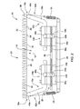
- Fig. 1 shows a perspective view of an embodiment of the inventive device for seat width adjustment for a motor vehicle seat, the representation in section in Fig. 2 is reproduced.
- the device 10 for seat width adjustment for a motor vehicle seat comprises a first adjusting element 12a and a second adjusting element 12b.
- Each of the adjusting elements 12i is assigned a guide element 16i, along which a planar piece of material 18 extending between the two adjusting elements 12i is stretched in such a way that a portion of the planar piece of material 18 forming a seating surface 20 can be adapted by changing the distance D of the two adjusting elements 12i ,
- the sheet-like piece of material 18 is for reasons of representability of the underlying components in Fig. 1 omitted, so in this context, the sectional view according to Fig. 2 referenced.
- the sheet-like material piece 18 is a textile under-spring fabric 22, in particular a breathable functional fabric.
- the textile Unterfederungsgewebe 22 is inelastic and tensioned by means of several tension springs 24.
- the tension springs 24 are connected to a base frame 26 of the motor vehicle seat.
- the spacer fabric 28 is a three-dimensional textile fabric in which two opposing textile outer surfaces 32 and 34 are held at a distance by spacing connecting threads 36.
- the spacer fabric 28 is protected by means of a cushion cover, not shown, surrounded.
- the two adjusting elements 12i are arranged to each other to change the distance D to each other.
- the adjustment elements 12i are designed as essentially L-shaped actuating limbs 38i and the guide elements 16i are designed as sliding rods 40i oriented transversely to the adjustment direction.
- the slide rods 40i have an outwardly curved course.
- a pairwise arrangement of the actuating limbs 38i is provided for each of the two adjusting elements 12i, a respective sliding bar 40i connecting the two actuating limbs 38i to each other in the manner of a bridge in the region of the first leg ends 42i. Furthermore, a torsion bar 46i connecting the two actuating limbs 38i in the region of second leg ends 44i is provided.
- the torsion bar 46i is mounted on the base frame 26 of the motor vehicle seat by means of an associated holder 48i in such a way that a rotary joint which can be articulated by means of the actuating device 14 is formed for pivoting the adjusting element 12i.
- the actuating device 14 for each of the two actuating legs 38i comprises a separate, acting on the respective rotary actuator actuator 50i, which cooperates by means of a manually and / or electromotively operable spindle drive 52, wherein the actuator 50i a transversely to the adjustment rotatably mounted threaded bushing 54i in which a threaded spindle 56 encompassed by the spindle drive 52 engages.
- the threaded spindle 56 is in turn with a hand crank and / or an electric motor for seat width adjustment in conjunction.
- the spindle drive 52 comprises two counter-rotating threaded spindle sections 58i, so depending on the direction of rotation of the threaded spindle 56, the distance between the two actuators 50i and thus the distance D between the two adjusting elements 12i increases or decreases.
Abstract
Description
Die Erfindung betrifft eine Einrichtung zur Sitzbreitenverstellung für einen Kraftfahrzeugsitz, mit einem ersten Verstellelement und einem zweiten Verstellelement, wobei sich ein zwischen den beiden Verstellelementen vorgesehener Abstand mittels einer Betätigungseinrichtung verändern lässt.The invention relates to a device for seat width adjustment for a motor vehicle seat, with a first adjusting element and a second adjusting element, wherein a distance provided between the two adjusting elements can be changed by means of an actuating device.
Ein in seiner Breite verstellbarer Fahrersitz für ein Kraftfahrzeug ist beispielsweise aus der
Es ist daher Aufgabe der vorliegenden Erfindung, eine bezüglich ihres Sitzkomforts verbesserte Einrichtung zur Sitzbreitenverstellung für einen Kraftfahrzeugsitz anzugeben.It is therefore an object of the present invention to provide an improved seat-comfort improved seat width adjustment device for a motor vehicle seat.
Diese Aufgabe wird durch eine Einrichtung zur Sitzbreitenverstellung mit den Merkmalen des Patentanspruchs 1 gelöst.This object is achieved by a device for seat width adjustment with the features of
Die Einrichtung zur Sitzbreitenverstellung für einen Kraftfahrzeugsitz umfasst ein erstes Verstellelement und ein zweites Verstellelement, wobei sich ein zwischen den beiden Verstellelementen vorgesehener Abstand mittels einer Betätigungseinrichtung verändern lässt. Erfindungsgemäß ist jedem der Verstellelemente ein Führungselement zugeordnet, entlang dessen ein zwischen den beiden Verstellelementen verlaufendes flächenhaftes Materialstück derart gleitend gespannt ist, dass sich ein eine Sitzfläche bildender Anteil des flächenhaften Materialstücks durch Veränderung des Abstands der beiden Verstellelemente anpassen lässt. Mit anderen Worten besteht die gesamte Sitzfläche aus ein und demselben Material, sodass mögliche Beeinträchtigungen des Sitzkomforts aufgrund eines inhomogenen Belastungsverhaltens der Sitzfläche von vornherein ausgeschlossen werden können.The device for seat width adjustment for a motor vehicle seat comprises a first adjusting element and a second adjusting element, wherein a distance provided between the two adjusting elements by means of an actuating device can change. According to the invention, a guide element is associated with each of the adjusting elements, along which a planar piece of material extending between the two adjusting elements is stretched in such a way that a portion of the planar piece of material forming a seating surface can be adjusted by changing the distance between the two adjusting elements. In other words, the entire seat consists of one and the same material, so that possible adverse effects on the seating comfort due to an inhomogeneous load behavior of the seat can be ruled out from the outset.
Vorteilhafte Ausführungen der erfindungsgemäßen Einrichtung zur Sitzbreitenverstellung gehen aus den Unteransprüchen hervor.Advantageous embodiments of the inventive device for seat width adjustment will become apparent from the dependent claims.
Vorzugsweise handelt es sich bei dem flächenhaften Materialstück um ein textiles Unterfederungsgewebe. Dem textilen Unterfederungsgewebe lässt sich durch entsprechende Vorgabe des Faserverlaufs sowie der Fasereigenschaften gezielt ein gewünschtes Belastungsverhalten aufprägen. Das textile Unterfederungsgewebe ist insbesondere als atmungsaktives Funktionsgewebe ausgebildet.Preferably, the sheet-like material piece is a textile underpinning fabric. The textile Unterfederungsgewebe can be imposed by appropriate specification of the fiber flow and the fiber properties targeted a desired load behavior. The textile lower suspension fabric is designed in particular as a breathable functional fabric.
Auf dem textilen Unterfederungsgewebe kann ein aus einem Abstandsgewirke bestehendes Sitz- und/oder Rückenpolster angebracht sein. Das Sitz- und/oder Rückenpolster ist beispielsweise mittels Klettverschlüssen abnehmbar auf der durch das flächenhafte Materialstück gebildeten Sitzfläche befestigt. Bei dem Abstandsgewirke handelt es sich um ein dreidimensionales Textilgewebe, bei dem zwei gegenüberliegende textile Außenflächen durch abstandshaltende Verbindungsfäden auf Distanz gehalten werden. Der charakteristische Aufbau des Abstandsgewirkes führt nicht nur zu einer verbesserten Feuchtigkeitsableitung und Luftdurchlässigkeit eines damit ausgestatteten Sitz- und/oder Rückenpolsters, sondern auch zu einem definierten elastischen Verhalten in Längs- und Querrichtung.On the textile Unterfederungsgewebe consisting of a spacer knit seat and / or back cushion may be attached. The seat and / or back pad is removably attached, for example by means of Velcro straps on the seat surface formed by the sheet-like piece of material. The spacer fabric is a three-dimensional textile fabric, in which two opposing outer textile surfaces are kept at a distance by spacing connecting threads. The characteristic structure of the spacer knitted fabric does not lead only to an improved moisture dissipation and air permeability of a seat and / or back cushion equipped with it, but also to a defined elastic behavior in the longitudinal and transverse directions.
Des Weiteren besteht die Möglichkeit, dass das flächenhafte Materialstück inelastisch ausgebildet und mittels mehrerer Zugfedern gespannt ist. Die Zugfedern sind beispielsweise mit einem Grundrahmen des Kraftfahrzeugsitzes verbunden. Durch Austausch der Zugfedern lässt sich die Nachgiebigkeit der Sitzfläche auch nachträglich an unterschiedliche Fahrergewichte und Sitzgewohnheiten anpassen.Furthermore, there is the possibility that the sheet-like piece of material is formed inelastic and tensioned by means of several tension springs. The tension springs are connected for example to a base frame of the motor vehicle seat. By replacing the tension springs, the resilience of the seat can also be subsequently adapted to different rider weights and sitting habits.
Vorzugsweise sind die beiden Verstellelemente zur Veränderung des Abstands zueinander verschwenkbar angeordnet. Die Verstellelemente sind hierzu mittels entsprechender Drehgelenke an einem Grundrahmen des Kraftfahrzeugsitzes angebracht. Die Verwendung von Drehgelenken führt zu einem besonders kompakten und robusten Aufbau der Betätigungseinrichtung. Zusätzlich oder alternativ können die Verstellelemente zur Veränderung des Abstands zueinander längsverschiebbar angeordnet sein. In diesem Fall kann eine beim Verschwenken der Verstellelemente zwangsläufig auftretende Höhenänderung der Sitzfläche vermieden oder zumindest reduziert werden.Preferably, the two adjusting elements are arranged to each other to change the distance pivotable. The adjusting elements are for this purpose mounted by means of corresponding hinges on a base frame of the vehicle seat. The use of hinges leads to a particularly compact and robust construction of the actuator. Additionally or alternatively, the adjusting elements can be arranged to be longitudinally displaceable relative to one another to change the distance. In this case, a change in height of the seat surface necessarily occurring during pivoting of the adjusting elements can be avoided or at least reduced.
Die Verstellelemente können ferner als im Wesentlichen L-förmige Betätigungsschenkel ausgebildet sein, wobei im Bereich eines ersten Schenkelendes das Führungselement und im Bereich eines zweiten Schenkelendes ein mit einem Grundrahmen des Kraftfahrzeugsitzes verbundenes Drehgelenk angeordnet ist. Das Drehgelenk ist zum Verschwenken des Verstellelements mittels der Betätigungseinrichtung anlenkbar, wobei die aufgrund der L-förmigen Ausbildung der Betätigungsschenkel gegebenen Hebelverhältnisse ein Verschwenken des Verstellelements begünstigen.The adjusting elements can furthermore be designed as essentially L-shaped actuating limbs, the guide element being arranged in the region of a first limb end and a swivel joint connected to a base frame of the motor vehicle seat in the region of a second limb end. The swivel joint is pivotable for pivoting the adjusting element by means of the actuating device, wherein the given due to the L-shaped configuration of the actuating limbs leverage conditions favor a pivoting of the adjusting element.
Zur Anlenkung des Drehgelenks kann die Betätigungseinrichtung einen an dem Drehgelenk angreifenden Betätigungsgeber umfassen, der mittels eines manuell und/oder elektromotorisch betätigbaren Spindelantriebs zusammenwirkt. Genauer gesagt kann der Betätigungsgeber eine quer zur Verstellrichtung drehbar gelagerte Gewindebuchse aufweisen, in die eine von dem Spindelantrieb umfasste Gewindespindel eingreift. Die Gewindespindel steht ihrerseits mit einer Handkurbel und/oder einem Elektromotor zur Sitzbreitenverstellung in Verbindung.For articulation of the rotary joint, the actuating device may comprise a force acting on the pivot actuator, which cooperates by means of a manually and / or electromotively operable spindle drive. More specifically, the actuator may have a transverse to the adjustment rotatably mounted threaded bushing, in which engages a threaded spindle encompassed by the spindle drive. The threaded spindle is in turn connected to a hand crank and / or an electric motor for seat width adjustment.
Um ein gegensinniges Verschwenken der beiden Betätigungsschenkel zu ermöglichen, kann die Betätigungseinrichtung für jeden der beiden Betätigungsschenkel einen eigenen Betätigungsgeber aufweisen. Der Spindelantrieb umfasst in diesem Fall zwei gegenläufig ausgebildete Gewindespindelabschnitte.In order to allow an opposite pivoting of the two actuating limbs, the actuating device may have its own actuator for each of the two actuating limbs. The spindle drive comprises in this case two counter-rotating threaded spindle sections.
Das Führungselement ist beispielsweise als quer zur Verstellrichtung orientierter Gleitstab ausgebildet. Zur Erhöhung der Verwindungssteifigkeit ist es denkbar, dass für jedes der beiden Verstellelemente eine paarweise Anordnung der Betätigungsschenkel vorgesehen ist, wobei der Gleitstab die beiden Betätigungsschenkel brückenförmig im Bereich des ersten Schenkelendes miteinander verbindet. Des Weiteren kann ein die beiden Betätigungsschenkel im Bereich des zweiten Schenkelendes verbindender Drehstab vorgesehen sein, der derart an einem Grundrahmen des Kraftfahrzeugsitzes gelagert ist, dass dieser ein Drehgelenk zum Verschwenken des Verstellelements bildet.The guide element is designed, for example, as a transverse to the adjustment oriented sliding rod. To increase the torsional rigidity, it is conceivable that a pairwise arrangement of the actuating limbs is provided for each of the two adjusting elements, wherein the sliding rod connects the two actuating limbs bridge-shaped in the region of the first leg end. Furthermore, a torsion bar connecting the two actuating limbs in the region of the second limb end can be provided which thus fits to a base frame of the Motor vehicle seat is mounted, that this forms a hinge for pivoting the adjusting element.
Um der durch das flächenhafte Materialstück gebildeten Sitzfläche einen ergonomischen Oberflächenverlauf aufzuprägen, besteht die Möglichkeit, dass der Gleitstab einen nach außen gebogenen Verlauf aufweist. Ein derartiger Verlauf führt zu einer sitzmuldenartigen Ausformung der durch das flächenhafte Materialstück gebildeten Sitzfläche.In order to impart an ergonomic surface course to the seat surface formed by the planar piece of material, it is possible for the slide rod to have an outwardly curved course. Such a course leads to a seat trough-like shape of the seat surface formed by the sheet-like piece of material.
Die erfindungsgemäße Einrichtung zur Sitzbreitenverstellung wird im Folgenden anhand der beigefügten Zeichnungen näher erläutert. Dabei sind hinsichtlich ihrer Funktion übereinstimmende bzw. vergleichbare Bauteile mit denselben Bezugszeichen gekennzeichnet. Es zeigen:
- Fig. 1
- eine perspektivische Ansicht eines Ausführungsbeispiels der erfindungsgemäßen Einrichtung zur Sitzbreitenverstellung für einen Kraftfahrzeugsitz, und
- Fig. 2
- eine Schnittdarstellung des in
Fig. 1 wiedergegebenen Ausführungsbeispiels der erfindungsgemäßen Einrichtung zur Sitzbreitenverstellung.
- Fig. 1
- a perspective view of an embodiment of the inventive device for seat width adjustment for a motor vehicle seat, and
- Fig. 2
- a sectional view of the in
Fig. 1 reproduced embodiment of the inventive device for seat width adjustment.
Die Einrichtung 10 zur Sitzbreitenverstellung für einen Kraftfahrzeugsitz umfasst ein erstes Verstellelement 12a und ein zweites Verstellelement 12b. Ein zwischen den beiden Verstellelementen 12i (i = a, b) vorgesehener Abstand D lässt sich mittels einer Betätigungseinrichtung 14 verändern. Jedem der Verstellelemente 12i ist ein Führungselement 16i zugeordnet, entlang dessen ein zwischen den beiden Verstellelementen 12i verlaufendes flächenhaftes Materialstück 18 derart gleitend gespannt ist, dass sich ein eine Sitzfläche 20 bildender Anteil des flächenhaften Materialstücks 18 durch Veränderung des Abstands D der beiden Verstellelemente 12i anpassen lässt. Das flächenhafte Materialstück 18 ist aus Gründen der Darstellbarkeit der darunter befindlichen Komponenten in
Im vorliegenden Fall handelt es sich bei dem flächenhaften Materialstück 18 um ein textiles Unterfederungsgewebe 22, insbesondere ein atmungsaktives Funktionsgewebe. Das textile Unterfederungsgewebe 22 ist inelastisch ausgebildet und mittels mehrerer Zugfedern 24 gespannt. Die Zugfedern 24 sind mit einem Grundrahmen 26 des Kraftfahrzeugsitzes verbunden.In the present case, the sheet-
Auf dem die Sitzfläche 20 bildendenden Anteil des textilen Unterfederungsgewebes 22 ist ein aus einem Abstandsgewirke 28 bestehendes Sitz- und/oder Rückenpolster mittels mehrerer Klettverschlüsse 30 abnehmbar befestigt. Bei dem Abstandsgewirke 28 handelt es sich um ein dreidimensionales Textilgewebe, bei dem zwei gegenüberliegende textile Außenflächen 32 und 34 durch abstandshaltende Verbindungsfäden 36 auf Distanz gehalten werden. Das Abstandsgewirke 28 ist mittels eines nicht dargestellten Polsterbezugs schützend umgeben.On the
Die beiden Verstellelemente 12i sind zur Veränderung des Abstands D zueinander verschwenkbar angeordnet. Beispielsgemäß sind die Verstellelemente 12i als im Wesentlichen L-förmige Betätigungsschenkel 38i und die Führungselemente 16i als quer zur Verstellrichtung orientierte Gleitstäbe 40i ausgebildet. Die Gleitstäbe 40i weisen einen nach außen gebogenen Verlauf auf.The two adjusting elements 12i are arranged to each other to change the distance D to each other. According to the example, the adjustment elements 12i are designed as essentially L-shaped actuating limbs 38i and the guide elements 16i are designed as sliding rods 40i oriented transversely to the adjustment direction. The slide rods 40i have an outwardly curved course.
Zur Erhöhung der Verwindungssteifigkeit ist für jedes der beiden Verstellelemente 12i eine paarweise Anordnung der Betätigungsschenkel 38i vorgesehen, wobei ein jeweiliger Gleitstab 40i die beiden Betätigungsschenkel 38i brückenförmig im Bereich erster Schenkelenden 42i miteinander verbindet. Des Weiteren ist ein die beiden Betätigungsschenkel 38i im Bereich zweiter Schenkelenden 44i jeweils verbindender Drehstab 46i vorgesehen. Der Drehstab 46i ist derart mittels zugehöriger Halter 48i an dem Grundrahmen 26 des Kraftfahrzeugsitzes gelagert, dass ein mittels der Betätigungseinrichtung 14 anlenkbares Drehgelenk zum Verschwenken des Verstellelements 12i gebildet wird.To increase the torsional stiffness, a pairwise arrangement of the actuating limbs 38i is provided for each of the two adjusting elements 12i, a respective sliding bar 40i connecting the two actuating limbs 38i to each other in the manner of a bridge in the region of the first leg ends 42i. Furthermore, a torsion bar 46i connecting the two actuating limbs 38i in the region of second leg ends 44i is provided. The torsion bar 46i is mounted on the
Zur Anlenkung des Drehgelenks umfasst die Betätigungseinrichtung 14 für jeden der beiden Betätigungsschenkel 38i einen eigenen, an dem jeweiligen Drehgelenk angreifenden Betätigungsgeber 50i, der mittels eines manuell und/oder elektromotorisch betätigbaren Spindelantriebs 52 zusammenwirkt, wobei die Betätigungsgeber 50i eine quer zur Verstellrichtung drehbar gelagerte Gewindebuchse 54i aufweisen, in die eine von dem Spindelantrieb 52 umfasste Gewindespindel 56 eingreift. Die Gewindespindel 56 steht ihrerseits mit einer Handkurbel und/oder einem Elektromotor zur Sitzbreitenverstellung in Verbindung.For the articulation of the rotary joint, the
Um ein gegensinniges Verschwenken der beiden Betätigungsschenkel 38i zu ermöglichen, umfasst der Spindelantrieb 52 zwei gegenläufig ausgebildete Gewindespindelabschnitte 58i, sodass je nach Drehrichtung der Gewindespindel 56 der Abstand zwischen den beiden Betätigungsgebern 50i und damit der Abstand D zwischen den beiden Verstellelementen 12i zu- oder abnimmt.In order to allow an opposite pivoting of the two actuating legs 38i, the
Claims (11)
Applications Claiming Priority (1)
| Application Number | Priority Date | Filing Date | Title |
|---|---|---|---|
| DE102011078122A DE102011078122A1 (en) | 2011-06-27 | 2011-06-27 | Seat width adjustment device for a motor vehicle seat |
Publications (2)
| Publication Number | Publication Date |
|---|---|
| EP2540558A1 true EP2540558A1 (en) | 2013-01-02 |
| EP2540558B1 EP2540558B1 (en) | 2016-08-03 |
Family
ID=46319022
Family Applications (1)
| Application Number | Title | Priority Date | Filing Date |
|---|---|---|---|
| EP12172744.0A Active EP2540558B1 (en) | 2011-06-27 | 2012-06-20 | Device for adjusting the width of a motor vehicle seat |
Country Status (3)
| Country | Link |
|---|---|
| US (1) | US8646844B2 (en) |
| EP (1) | EP2540558B1 (en) |
| DE (1) | DE102011078122A1 (en) |
Families Citing this family (10)
| Publication number | Priority date | Publication date | Assignee | Title |
|---|---|---|---|---|
| US20150061336A1 (en) * | 2013-08-29 | 2015-03-05 | Wan-Ching KU | Chair with seat of adjustable length |
| EP2883742A1 (en) * | 2013-12-11 | 2015-06-17 | Airbus Operations GmbH | Seat modification assembly and aircraft passenger seat comprising a seat modification assembly |
| USD804836S1 (en) | 2016-09-16 | 2017-12-12 | Francesco Lieberman | Canopy swing chair |
| DE102016219105A1 (en) | 2016-09-30 | 2018-04-05 | Brose Fahrzeugteile Gmbh & Co. Kg, Coburg | Adjusting device with spindle drive for a seat element of a vehicle seat |
| DE102016220650A1 (en) * | 2016-10-20 | 2018-04-26 | Bayerische Motoren Werke Aktiengesellschaft | motor vehicle |
| CN106740287A (en) * | 2017-01-20 | 2017-05-31 | 广州名博汽车零部件有限公司 | A kind of automobile cushion skeleton structure |
| GB2563286B (en) * | 2017-06-09 | 2019-11-20 | Ford Global Tech Llc | A motor vehicle seating system with increased flexibility of seating arrangements |
| US10836495B2 (en) | 2018-10-24 | 2020-11-17 | Safran Seats Usa Llc | Passenger seat with suspended seat diaphragm |
| US11642993B2 (en) * | 2019-01-07 | 2023-05-09 | Adient Us Llc | Seat mounting structure for a seat of a vehicle and vehicle and center seat structure |
| CN112644346B (en) * | 2021-01-14 | 2022-02-25 | 海啊科技有限公司 | Automobile cushion with adjustable side wings |
Citations (3)
| Publication number | Priority date | Publication date | Assignee | Title |
|---|---|---|---|---|
| FR2587201A1 (en) * | 1985-09-13 | 1987-03-20 | Poirier Ets | Chair seat, in particular for invalid wheelchair |
| DE4339114A1 (en) * | 1993-11-16 | 1995-05-18 | Daimler Benz Ag | Cushion for truck seat |
| DE102006020671A1 (en) | 2006-05-04 | 2007-11-08 | Bayerische Motoren Werke Ag | Seat for a vehicle comprises two seat halves which can be adjusted and joined together via an elastic intermediate element |
Family Cites Families (11)
| Publication number | Priority date | Publication date | Assignee | Title |
|---|---|---|---|---|
| US4462635A (en) * | 1980-02-29 | 1984-07-31 | Lance Mark A | Seat with adjustable back support |
| US4636000A (en) * | 1984-09-28 | 1987-01-13 | Tachikawa Spring Co. Ltd. | Side support device in a vehicle seat |
| US4712834A (en) * | 1986-12-18 | 1987-12-15 | Simula, Inc. | Adjustable seat cushion with tension limiting means |
| FR2647727B1 (en) * | 1989-06-02 | 1994-10-28 | Ampafrance | CHILD SEAT ADJUSTABLE WIDTH |
| DE19920216B4 (en) * | 1999-05-03 | 2012-06-14 | Volkswagen Ag | Automotive seat |
| DE20100018U1 (en) * | 2000-09-01 | 2002-02-21 | Johnson Controls Gmbh | Backrest with adjustable support |
| DE10057449A1 (en) * | 2000-11-20 | 2002-05-29 | Lear Corp Gmbh & Co Kg | Side part for seat esp. for motor vehicles has long support bracket tensioned into positions and moved by traction devices relative to neighboring seat or to seat front |
| US6672666B2 (en) * | 2001-12-03 | 2004-01-06 | GRA★MAG Truck Interior Systems, L.L.C. | Mesh seat with displaceable bolsters |
| WO2004026080A1 (en) * | 2002-09-03 | 2004-04-01 | Kabushiki Kaisha Toyota Chuo Kenkyusho | Seat |
| DE102009040884A1 (en) * | 2009-09-09 | 2011-03-10 | GM Global Technology Operations, Inc., Detroit | Backrest for seat arrangement of motor vehicle seat, has planar formation fastened to retaining units such that formation extends under formation of backrest surface section of backrest surface between units over supporting structure |
| US20120286552A1 (en) * | 2011-05-11 | 2012-11-15 | Martin Kace | Wheelchair seat assembly |
-
2011
- 2011-06-27 DE DE102011078122A patent/DE102011078122A1/en not_active Withdrawn
-
2012
- 2012-06-20 EP EP12172744.0A patent/EP2540558B1/en active Active
- 2012-06-21 US US13/529,362 patent/US8646844B2/en active Active
Patent Citations (3)
| Publication number | Priority date | Publication date | Assignee | Title |
|---|---|---|---|---|
| FR2587201A1 (en) * | 1985-09-13 | 1987-03-20 | Poirier Ets | Chair seat, in particular for invalid wheelchair |
| DE4339114A1 (en) * | 1993-11-16 | 1995-05-18 | Daimler Benz Ag | Cushion for truck seat |
| DE102006020671A1 (en) | 2006-05-04 | 2007-11-08 | Bayerische Motoren Werke Ag | Seat for a vehicle comprises two seat halves which can be adjusted and joined together via an elastic intermediate element |
Also Published As
| Publication number | Publication date |
|---|---|
| EP2540558B1 (en) | 2016-08-03 |
| US8646844B2 (en) | 2014-02-11 |
| DE102011078122A1 (en) | 2012-12-27 |
| US20120326478A1 (en) | 2012-12-27 |
Similar Documents
| Publication | Publication Date | Title |
|---|---|---|
| EP2540558B1 (en) | Device for adjusting the width of a motor vehicle seat | |
| DE19942351B4 (en) | Seat depth adjustment device for a vehicle seat | |
| DE60110591T2 (en) | SPINE COLUMN FOR VEHICLE SEATS | |
| DE102015106386B4 (en) | Armrest assembly for a seat, in particular for a vehicle seat and vehicle seat | |
| DE2345254C2 (en) | Back cushion or backrest | |
| DE10145206B4 (en) | Backrest for a motor vehicle seat | |
| EP2719575B1 (en) | Vehicle seat with variable backrest shape | |
| DE102014011884B4 (en) | Vehicle seat with adjustable backrest | |
| DE102009020034B4 (en) | Vehicle seat, in particular motor vehicle seat | |
| EP1725428A1 (en) | Regulating device for a lateral part of a seat | |
| EP0434660B1 (en) | Anatomically adjustable support | |
| EP2985177B1 (en) | Vehicle seat with adjustable backrest | |
| WO2010078861A1 (en) | Apparatus for adjusting the hardness and geometry of seating elements of a motor vehicle | |
| DE102014207972A1 (en) | Seating furniture and fitting for this | |
| EP2301794B1 (en) | Vehicle seat with ability to adjust seat depth and method for adjusting the seat depth of a seat section of a vehicle seat | |
| EP3568317A1 (en) | Lumbar support for a seat | |
| EP1881913B1 (en) | Lumbar support for a motor vehicle seat | |
| DE602005004111T2 (en) | Support structure for a seat with a table function and corresponding Sitzfederungsanordnung | |
| DE102010039353A1 (en) | Seat-back structure for backrest of motor vehicle seat, has backrest frame, which has front side and extends along backrest longitudinal direction | |
| WO2017029409A1 (en) | Multidimensional chair suspension arrangement | |
| EP3003963B1 (en) | Modular saddle tree with head iron | |
| DE202005019654U1 (en) | Backrest and chair | |
| DE102018109641A1 (en) | VEHICLE SEAT | |
| DE19850121B4 (en) | Adjustable lumbar support | |
| DE10355659A1 (en) | lumbar support |
Legal Events
| Date | Code | Title | Description |
|---|---|---|---|
| PUAI | Public reference made under article 153(3) epc to a published international application that has entered the european phase |
Free format text: ORIGINAL CODE: 0009012 |
|
| AK | Designated contracting states |
Kind code of ref document: A1 Designated state(s): AL AT BE BG CH CY CZ DE DK EE ES FI FR GB GR HR HU IE IS IT LI LT LU LV MC MK MT NL NO PL PT RO RS SE SI SK SM TR |
|
| AX | Request for extension of the european patent |
Extension state: BA ME |
|
| 17P | Request for examination filed |
Effective date: 20130702 |
|
| RBV | Designated contracting states (corrected) |
Designated state(s): AL AT BE BG CH CY CZ DE DK EE ES FI FR GB GR HR HU IE IS IT LI LT LU LV MC MK MT NL NO PL PT RO RS SE SI SK SM TR |
|
| GRAP | Despatch of communication of intention to grant a patent |
Free format text: ORIGINAL CODE: EPIDOSNIGR1 |
|
| INTG | Intention to grant announced |
Effective date: 20160303 |
|
| GRAS | Grant fee paid |
Free format text: ORIGINAL CODE: EPIDOSNIGR3 |
|
| GRAA | (expected) grant |
Free format text: ORIGINAL CODE: 0009210 |
|
| AK | Designated contracting states |
Kind code of ref document: B1 Designated state(s): AL AT BE BG CH CY CZ DE DK EE ES FI FR GB GR HR HU IE IS IT LI LT LU LV MC MK MT NL NO PL PT RO RS SE SI SK SM TR |
|
| REG | Reference to a national code |
Ref country code: GB Ref legal event code: FG4D Free format text: NOT ENGLISH |
|
| REG | Reference to a national code |
Ref country code: CH Ref legal event code: EP Ref country code: AT Ref legal event code: REF Ref document number: 817099 Country of ref document: AT Kind code of ref document: T Effective date: 20160815 |
|
| REG | Reference to a national code |
Ref country code: IE Ref legal event code: FG4D Free format text: LANGUAGE OF EP DOCUMENT: GERMAN |
|
| REG | Reference to a national code |
Ref country code: DE Ref legal event code: R096 Ref document number: 502012007824 Country of ref document: DE |
|
| REG | Reference to a national code |
Ref country code: NL Ref legal event code: MP Effective date: 20160803 |
|
| REG | Reference to a national code |
Ref country code: LT Ref legal event code: MG4D |
|
| PG25 | Lapsed in a contracting state [announced via postgrant information from national office to epo] |
Ref country code: FI Free format text: LAPSE BECAUSE OF FAILURE TO SUBMIT A TRANSLATION OF THE DESCRIPTION OR TO PAY THE FEE WITHIN THE PRESCRIBED TIME-LIMIT Effective date: 20160803 Ref country code: HR Free format text: LAPSE BECAUSE OF FAILURE TO SUBMIT A TRANSLATION OF THE DESCRIPTION OR TO PAY THE FEE WITHIN THE PRESCRIBED TIME-LIMIT Effective date: 20160803 Ref country code: NO Free format text: LAPSE BECAUSE OF FAILURE TO SUBMIT A TRANSLATION OF THE DESCRIPTION OR TO PAY THE FEE WITHIN THE PRESCRIBED TIME-LIMIT Effective date: 20161103 Ref country code: IS Free format text: LAPSE BECAUSE OF FAILURE TO SUBMIT A TRANSLATION OF THE DESCRIPTION OR TO PAY THE FEE WITHIN THE PRESCRIBED TIME-LIMIT Effective date: 20161203 Ref country code: LT Free format text: LAPSE BECAUSE OF FAILURE TO SUBMIT A TRANSLATION OF THE DESCRIPTION OR TO PAY THE FEE WITHIN THE PRESCRIBED TIME-LIMIT Effective date: 20160803 Ref country code: RS Free format text: LAPSE BECAUSE OF FAILURE TO SUBMIT A TRANSLATION OF THE DESCRIPTION OR TO PAY THE FEE WITHIN THE PRESCRIBED TIME-LIMIT Effective date: 20160803 Ref country code: NL Free format text: LAPSE BECAUSE OF FAILURE TO SUBMIT A TRANSLATION OF THE DESCRIPTION OR TO PAY THE FEE WITHIN THE PRESCRIBED TIME-LIMIT Effective date: 20160803 |
|
| PG25 | Lapsed in a contracting state [announced via postgrant information from national office to epo] |
Ref country code: GR Free format text: LAPSE BECAUSE OF FAILURE TO SUBMIT A TRANSLATION OF THE DESCRIPTION OR TO PAY THE FEE WITHIN THE PRESCRIBED TIME-LIMIT Effective date: 20161104 Ref country code: LV Free format text: LAPSE BECAUSE OF FAILURE TO SUBMIT A TRANSLATION OF THE DESCRIPTION OR TO PAY THE FEE WITHIN THE PRESCRIBED TIME-LIMIT Effective date: 20160803 Ref country code: PL Free format text: LAPSE BECAUSE OF FAILURE TO SUBMIT A TRANSLATION OF THE DESCRIPTION OR TO PAY THE FEE WITHIN THE PRESCRIBED TIME-LIMIT Effective date: 20160803 Ref country code: PT Free format text: LAPSE BECAUSE OF FAILURE TO SUBMIT A TRANSLATION OF THE DESCRIPTION OR TO PAY THE FEE WITHIN THE PRESCRIBED TIME-LIMIT Effective date: 20161205 Ref country code: SE Free format text: LAPSE BECAUSE OF FAILURE TO SUBMIT A TRANSLATION OF THE DESCRIPTION OR TO PAY THE FEE WITHIN THE PRESCRIBED TIME-LIMIT Effective date: 20160803 Ref country code: ES Free format text: LAPSE BECAUSE OF FAILURE TO SUBMIT A TRANSLATION OF THE DESCRIPTION OR TO PAY THE FEE WITHIN THE PRESCRIBED TIME-LIMIT Effective date: 20160803 |
|
| PG25 | Lapsed in a contracting state [announced via postgrant information from national office to epo] |
Ref country code: EE Free format text: LAPSE BECAUSE OF FAILURE TO SUBMIT A TRANSLATION OF THE DESCRIPTION OR TO PAY THE FEE WITHIN THE PRESCRIBED TIME-LIMIT Effective date: 20160803 Ref country code: RO Free format text: LAPSE BECAUSE OF FAILURE TO SUBMIT A TRANSLATION OF THE DESCRIPTION OR TO PAY THE FEE WITHIN THE PRESCRIBED TIME-LIMIT Effective date: 20160803 |
|
| REG | Reference to a national code |
Ref country code: DE Ref legal event code: R097 Ref document number: 502012007824 Country of ref document: DE |
|
| PG25 | Lapsed in a contracting state [announced via postgrant information from national office to epo] |
Ref country code: SM Free format text: LAPSE BECAUSE OF FAILURE TO SUBMIT A TRANSLATION OF THE DESCRIPTION OR TO PAY THE FEE WITHIN THE PRESCRIBED TIME-LIMIT Effective date: 20160803 Ref country code: SK Free format text: LAPSE BECAUSE OF FAILURE TO SUBMIT A TRANSLATION OF THE DESCRIPTION OR TO PAY THE FEE WITHIN THE PRESCRIBED TIME-LIMIT Effective date: 20160803 Ref country code: CZ Free format text: LAPSE BECAUSE OF FAILURE TO SUBMIT A TRANSLATION OF THE DESCRIPTION OR TO PAY THE FEE WITHIN THE PRESCRIBED TIME-LIMIT Effective date: 20160803 Ref country code: BG Free format text: LAPSE BECAUSE OF FAILURE TO SUBMIT A TRANSLATION OF THE DESCRIPTION OR TO PAY THE FEE WITHIN THE PRESCRIBED TIME-LIMIT Effective date: 20161103 Ref country code: DK Free format text: LAPSE BECAUSE OF FAILURE TO SUBMIT A TRANSLATION OF THE DESCRIPTION OR TO PAY THE FEE WITHIN THE PRESCRIBED TIME-LIMIT Effective date: 20160803 |
|
| PLBE | No opposition filed within time limit |
Free format text: ORIGINAL CODE: 0009261 |
|
| STAA | Information on the status of an ep patent application or granted ep patent |
Free format text: STATUS: NO OPPOSITION FILED WITHIN TIME LIMIT |
|
| REG | Reference to a national code |
Ref country code: FR Ref legal event code: PLFP Year of fee payment: 6 |
|
| 26N | No opposition filed |
Effective date: 20170504 |
|
| PG25 | Lapsed in a contracting state [announced via postgrant information from national office to epo] |
Ref country code: SI Free format text: LAPSE BECAUSE OF FAILURE TO SUBMIT A TRANSLATION OF THE DESCRIPTION OR TO PAY THE FEE WITHIN THE PRESCRIBED TIME-LIMIT Effective date: 20160803 |
|
| PG25 | Lapsed in a contracting state [announced via postgrant information from national office to epo] |
Ref country code: MC Free format text: LAPSE BECAUSE OF FAILURE TO SUBMIT A TRANSLATION OF THE DESCRIPTION OR TO PAY THE FEE WITHIN THE PRESCRIBED TIME-LIMIT Effective date: 20160803 |
|
| REG | Reference to a national code |
Ref country code: CH Ref legal event code: PL |
|
| REG | Reference to a national code |
Ref country code: IE Ref legal event code: MM4A |
|
| PG25 | Lapsed in a contracting state [announced via postgrant information from national office to epo] |
Ref country code: CH Free format text: LAPSE BECAUSE OF NON-PAYMENT OF DUE FEES Effective date: 20170630 Ref country code: LI Free format text: LAPSE BECAUSE OF NON-PAYMENT OF DUE FEES Effective date: 20170630 Ref country code: LU Free format text: LAPSE BECAUSE OF NON-PAYMENT OF DUE FEES Effective date: 20170620 Ref country code: IE Free format text: LAPSE BECAUSE OF NON-PAYMENT OF DUE FEES Effective date: 20170620 |
|
| REG | Reference to a national code |
Ref country code: BE Ref legal event code: MM Effective date: 20170630 |
|
| REG | Reference to a national code |
Ref country code: FR Ref legal event code: PLFP Year of fee payment: 7 |
|
| REG | Reference to a national code |
Ref country code: AT Ref legal event code: MM01 Ref document number: 817099 Country of ref document: AT Kind code of ref document: T Effective date: 20170620 |
|
| PG25 | Lapsed in a contracting state [announced via postgrant information from national office to epo] |
Ref country code: BE Free format text: LAPSE BECAUSE OF NON-PAYMENT OF DUE FEES Effective date: 20170630 |
|
| PG25 | Lapsed in a contracting state [announced via postgrant information from national office to epo] |
Ref country code: MT Free format text: LAPSE BECAUSE OF FAILURE TO SUBMIT A TRANSLATION OF THE DESCRIPTION OR TO PAY THE FEE WITHIN THE PRESCRIBED TIME-LIMIT Effective date: 20160803 |
|
| PG25 | Lapsed in a contracting state [announced via postgrant information from national office to epo] |
Ref country code: AL Free format text: LAPSE BECAUSE OF FAILURE TO SUBMIT A TRANSLATION OF THE DESCRIPTION OR TO PAY THE FEE WITHIN THE PRESCRIBED TIME-LIMIT Effective date: 20160803 |
|
| PG25 | Lapsed in a contracting state [announced via postgrant information from national office to epo] |
Ref country code: AT Free format text: LAPSE BECAUSE OF NON-PAYMENT OF DUE FEES Effective date: 20170620 |
|
| PG25 | Lapsed in a contracting state [announced via postgrant information from national office to epo] |
Ref country code: HU Free format text: LAPSE BECAUSE OF FAILURE TO SUBMIT A TRANSLATION OF THE DESCRIPTION OR TO PAY THE FEE WITHIN THE PRESCRIBED TIME-LIMIT; INVALID AB INITIO Effective date: 20120620 |
|
| PG25 | Lapsed in a contracting state [announced via postgrant information from national office to epo] |
Ref country code: CY Free format text: LAPSE BECAUSE OF NON-PAYMENT OF DUE FEES Effective date: 20160803 |
|
| PG25 | Lapsed in a contracting state [announced via postgrant information from national office to epo] |
Ref country code: MK Free format text: LAPSE BECAUSE OF FAILURE TO SUBMIT A TRANSLATION OF THE DESCRIPTION OR TO PAY THE FEE WITHIN THE PRESCRIBED TIME-LIMIT Effective date: 20160803 |
|
| PG25 | Lapsed in a contracting state [announced via postgrant information from national office to epo] |
Ref country code: TR Free format text: LAPSE BECAUSE OF FAILURE TO SUBMIT A TRANSLATION OF THE DESCRIPTION OR TO PAY THE FEE WITHIN THE PRESCRIBED TIME-LIMIT Effective date: 20160803 |
|
| PGFP | Annual fee paid to national office [announced via postgrant information from national office to epo] |
Ref country code: FR Payment date: 20230626 Year of fee payment: 12 Ref country code: DE Payment date: 20230522 Year of fee payment: 12 |
|
| PGFP | Annual fee paid to national office [announced via postgrant information from national office to epo] |
Ref country code: IT Payment date: 20230620 Year of fee payment: 12 Ref country code: GB Payment date: 20230627 Year of fee payment: 12 |