EP2540485A1 - Composite material repair method, and composite material using same - Google Patents
Composite material repair method, and composite material using same Download PDFInfo
- Publication number
- EP2540485A1 EP2540485A1 EP11747496A EP11747496A EP2540485A1 EP 2540485 A1 EP2540485 A1 EP 2540485A1 EP 11747496 A EP11747496 A EP 11747496A EP 11747496 A EP11747496 A EP 11747496A EP 2540485 A1 EP2540485 A1 EP 2540485A1
- Authority
- EP
- European Patent Office
- Prior art keywords
- composite material
- staple
- repairing method
- delamination
- joining member
- Prior art date
- Legal status (The legal status is an assumption and is not a legal conclusion. Google has not performed a legal analysis and makes no representation as to the accuracy of the status listed.)
- Granted
Links
- 239000002131 composite material Substances 0.000 title claims abstract description 234
- 238000000034 method Methods 0.000 title claims abstract description 146
- 230000032798 delamination Effects 0.000 claims abstract description 95
- 238000005304 joining Methods 0.000 claims abstract description 89
- 238000002788 crimping Methods 0.000 claims description 29
- 239000000463 material Substances 0.000 claims description 28
- 230000007797 corrosion Effects 0.000 claims description 24
- 238000005260 corrosion Methods 0.000 claims description 24
- 239000000835 fiber Substances 0.000 claims description 17
- 229910001285 shape-memory alloy Inorganic materials 0.000 claims description 14
- 239000011248 coating agent Substances 0.000 claims description 12
- 238000000576 coating method Methods 0.000 claims description 12
- 238000005452 bending Methods 0.000 claims description 7
- 238000005536 corrosion prevention Methods 0.000 claims description 5
- 239000000565 sealant Substances 0.000 claims description 5
- 229920005989 resin Polymers 0.000 description 16
- 239000011347 resin Substances 0.000 description 16
- 230000001681 protective effect Effects 0.000 description 14
- 230000000694 effects Effects 0.000 description 12
- 239000000853 adhesive Substances 0.000 description 7
- 230000001070 adhesive effect Effects 0.000 description 7
- 229920001169 thermoplastic Polymers 0.000 description 6
- 239000004416 thermosoftening plastic Substances 0.000 description 6
- 230000002542 deteriorative effect Effects 0.000 description 5
- 238000005553 drilling Methods 0.000 description 5
- 230000006866 deterioration Effects 0.000 description 4
- 229910052751 metal Inorganic materials 0.000 description 4
- 239000002184 metal Substances 0.000 description 4
- 238000007789 sealing Methods 0.000 description 4
- 229920001187 thermosetting polymer Polymers 0.000 description 4
- 239000003566 sealing material Substances 0.000 description 3
- XLYOFNOQVPJJNP-UHFFFAOYSA-N water Substances O XLYOFNOQVPJJNP-UHFFFAOYSA-N 0.000 description 3
- 238000010586 diagram Methods 0.000 description 2
- 238000010438 heat treatment Methods 0.000 description 2
- 238000002347 injection Methods 0.000 description 2
- 239000007924 injection Substances 0.000 description 2
- 238000003780 insertion Methods 0.000 description 2
- 230000037431 insertion Effects 0.000 description 2
- 230000002250 progressing effect Effects 0.000 description 2
- 239000000243 solution Substances 0.000 description 2
- 229910001040 Beta-titanium Inorganic materials 0.000 description 1
- 241001481828 Glyptocephalus cynoglossus Species 0.000 description 1
- 229910000990 Ni alloy Inorganic materials 0.000 description 1
- HZEWFHLRYVTOIW-UHFFFAOYSA-N [Ti].[Ni] Chemical compound [Ti].[Ni] HZEWFHLRYVTOIW-UHFFFAOYSA-N 0.000 description 1
- 229910001566 austenite Inorganic materials 0.000 description 1
- 238000004140 cleaning Methods 0.000 description 1
- 238000001035 drying Methods 0.000 description 1
- 229910001026 inconel Inorganic materials 0.000 description 1
- 238000009413 insulation Methods 0.000 description 1
- 238000010030 laminating Methods 0.000 description 1
- 230000000979 retarding effect Effects 0.000 description 1
- 238000009966 trimming Methods 0.000 description 1
Images








Classifications
-
- B—PERFORMING OPERATIONS; TRANSPORTING
- B29—WORKING OF PLASTICS; WORKING OF SUBSTANCES IN A PLASTIC STATE IN GENERAL
- B29C—SHAPING OR JOINING OF PLASTICS; SHAPING OF MATERIAL IN A PLASTIC STATE, NOT OTHERWISE PROVIDED FOR; AFTER-TREATMENT OF THE SHAPED PRODUCTS, e.g. REPAIRING
- B29C73/00—Repairing of articles made from plastics or substances in a plastic state, e.g. of articles shaped or produced by using techniques covered by this subclass or subclass B29D
- B29C73/04—Repairing of articles made from plastics or substances in a plastic state, e.g. of articles shaped or produced by using techniques covered by this subclass or subclass B29D using preformed elements
-
- B—PERFORMING OPERATIONS; TRANSPORTING
- B29—WORKING OF PLASTICS; WORKING OF SUBSTANCES IN A PLASTIC STATE IN GENERAL
- B29C—SHAPING OR JOINING OF PLASTICS; SHAPING OF MATERIAL IN A PLASTIC STATE, NOT OTHERWISE PROVIDED FOR; AFTER-TREATMENT OF THE SHAPED PRODUCTS, e.g. REPAIRING
- B29C65/00—Joining or sealing of preformed parts, e.g. welding of plastics materials; Apparatus therefor
- B29C65/56—Joining or sealing of preformed parts, e.g. welding of plastics materials; Apparatus therefor using mechanical means or mechanical connections, e.g. form-fits
-
- B—PERFORMING OPERATIONS; TRANSPORTING
- B29—WORKING OF PLASTICS; WORKING OF SUBSTANCES IN A PLASTIC STATE IN GENERAL
- B29C—SHAPING OR JOINING OF PLASTICS; SHAPING OF MATERIAL IN A PLASTIC STATE, NOT OTHERWISE PROVIDED FOR; AFTER-TREATMENT OF THE SHAPED PRODUCTS, e.g. REPAIRING
- B29C73/00—Repairing of articles made from plastics or substances in a plastic state, e.g. of articles shaped or produced by using techniques covered by this subclass or subclass B29D
- B29C73/04—Repairing of articles made from plastics or substances in a plastic state, e.g. of articles shaped or produced by using techniques covered by this subclass or subclass B29D using preformed elements
- B29C73/06—Repairing of articles made from plastics or substances in a plastic state, e.g. of articles shaped or produced by using techniques covered by this subclass or subclass B29D using preformed elements using plugs sealing in the hole
-
- B—PERFORMING OPERATIONS; TRANSPORTING
- B64—AIRCRAFT; AVIATION; COSMONAUTICS
- B64F—GROUND OR AIRCRAFT-CARRIER-DECK INSTALLATIONS SPECIALLY ADAPTED FOR USE IN CONNECTION WITH AIRCRAFT; DESIGNING, MANUFACTURING, ASSEMBLING, CLEANING, MAINTAINING OR REPAIRING AIRCRAFT, NOT OTHERWISE PROVIDED FOR; HANDLING, TRANSPORTING, TESTING OR INSPECTING AIRCRAFT COMPONENTS, NOT OTHERWISE PROVIDED FOR
- B64F5/00—Designing, manufacturing, assembling, cleaning, maintaining or repairing aircraft, not otherwise provided for; Handling, transporting, testing or inspecting aircraft components, not otherwise provided for
- B64F5/40—Maintaining or repairing aircraft
-
- Y—GENERAL TAGGING OF NEW TECHNOLOGICAL DEVELOPMENTS; GENERAL TAGGING OF CROSS-SECTIONAL TECHNOLOGIES SPANNING OVER SEVERAL SECTIONS OF THE IPC; TECHNICAL SUBJECTS COVERED BY FORMER USPC CROSS-REFERENCE ART COLLECTIONS [XRACs] AND DIGESTS
- Y10—TECHNICAL SUBJECTS COVERED BY FORMER USPC
- Y10T—TECHNICAL SUBJECTS COVERED BY FORMER US CLASSIFICATION
- Y10T29/00—Metal working
- Y10T29/49—Method of mechanical manufacture
- Y10T29/49718—Repairing
- Y10T29/49732—Repairing by attaching repair preform, e.g., remaking, restoring, or patching
-
- Y—GENERAL TAGGING OF NEW TECHNOLOGICAL DEVELOPMENTS; GENERAL TAGGING OF CROSS-SECTIONAL TECHNOLOGIES SPANNING OVER SEVERAL SECTIONS OF THE IPC; TECHNICAL SUBJECTS COVERED BY FORMER USPC CROSS-REFERENCE ART COLLECTIONS [XRACs] AND DIGESTS
- Y10—TECHNICAL SUBJECTS COVERED BY FORMER USPC
- Y10T—TECHNICAL SUBJECTS COVERED BY FORMER US CLASSIFICATION
- Y10T428/00—Stock material or miscellaneous articles
- Y10T428/249921—Web or sheet containing structurally defined element or component
- Y10T428/249923—Including interlaminar mechanical fastener
Definitions
- the present invention relates to a repairing method for composite material for use as structural material of an aircraft or the like and a repaired composite material using this method, and in particular to join a delamination generated between layers of composite material that has been hardened.
- examples of a repairing method for a delamination between layers of composite material for use in aircraft structural material or the like include a resin injection method as described in Patent Literature 1, a gap filling method using repairing material after trimming as described in Patent Literature 2, a pin or staple fitting method described in Patent Literature 3 and 4, and a stitching method using fiber as described in Patent Literature 5.
- Patent Literature 1 has a difficulty that a resin injection cannot be carried out if a delamination generated between layers of composite material is slight.
- the invention of Patent Literature 1 and Patent Literature 2 have difficulties in controlling each process of cleaning, drying and bonding, so that time required for a repairing operation becomes increased.
- the invention described in Patent Literature 3 has a difficulty that the method is limited to the case of using thermoplastics composite material, and cannot be applicable to repairing for thermosetting composite material that cannot be softened by re-heating once the material has been hardened.
- the inventions described in Patent Literature 4 and Patent Literature 5 have a difficulty that the methods are limited to a stage where layers of composite material are still soft before they become cured, and cannot be applicable to repairing of composite material completely hardened.
- the present invention has been made in the light of the above facts, and has an object to provide a repairing method for composite material and a repaired composite material using this method, which are capable of readily repairing, in a short time, a delamination generated between layers of hardened composite material.
- the repairing method for composite material and the repaired composite material using this method according to the present invention provide the following solutions.
- a hole is drilled through a delamination generated between layers of hardened composite material, and a joining member is inserted into the hole so as to join the delamination gap.
- the hole is formed through the delamination generated between the layers of the composite material, and the joining member is so inserted into the hole as to join the delamination. Accordingly, even the delamination generated between the layers of the hardened composite material can be readily bonded. As a result, it is possible to reduce the time required for the repairing the delamination generated between the layers of the hardened composite material.
- sleeve may be inserted into the hole, and the joining member may be inserted through the sleeve.
- the sleeve is inserted into the hole formed through the delamination, and then, the joining member is inserted through the sleeve. Accordingly, the inner surface of the hole can be prevented from being damaged at the time of inserting the joining member through the hole and bending it. As a result, it is possible to prevent a further delamination from progressing, resulted from damage caused on the hole. Further, it is possible to present galvanic corrosion in such a combination of materials that cause deterioration of the galvanic corrosion resistance when the joining member directly comes in contact with the composite material.
- a bending process may be applied to an end portion of the joining member that is inserted through the hole.
- the end portion of the joining member inserted through the hole is bent in the bending process. Accordingly the joining member that joins the delamination can be prevented from becoming loose. As a result, it is possible to firmly join the delamination between the layers of the hardened composite material.
- an end portion of the joining member that is inserted through the hole may be crimped witch a crimping member.
- the end portion of the joining member that is inserted through the hole is crimped with the crimping member. Accordingly, the joining member that joins the delamination can be prevented from becoming loose, compared to the case without using the crimping member. As a result, it is possible to more firmly, join the delamination generated between the layers of the hardened composite material.
- an end portion of the joining member that is inserted through the hole may be covered with a sealant.
- the end portion of the joining member that is inserted through the hole and exposed on the surface of the layer of the composite material is covered with the sealant. Accordingly, water can be prevented from intruding between the joining member and the layers of the composite material. As a result, it is possible to readily and inexpensively prevent galvanic corrosion from being caused at the time of the repairing to join the delamination generated between the layers of the hardened composite material.
- a galvanic corrosion resistance material may be provided between the joining member and the layers of the composite material.
- the galvanic corrosion resistance material is provided between the layers of the composite material and the joining member. Accordingly, the galvanic corrosion can be prevented from occurring when the joining member comes in contact with the layers of the composite material. As a result, it is possible to prevent the joining member from deteriorating, resulted from galvanic corrosion after the repairing of the delamination generated between the layers of the hardened composite material.
- the joining member may be in a quadrilateral cross sectional shape.
- the delamination is joined by use of the joining member in a quadrilateral cross sectional shape. Accordingly, strength to join the delamination can be enhanced. As a result, it is possible to more firmly join the delamination generated between the layers of the hardened composite material.
- the joining member may include a staple having plural legs.
- the delamination is joined by use of the staple having plural legs. Accordingly, it is possible to more firmly join the delamination generated between the Layers of the composite material. Further, there is no need to join the delamination by use of plural staples, thereby reducing the working time for joining the delamination.
- the staple may include four legs, and each of the legs may be provided on each side of the staple in a quadrilateral shape.
- the staple is used as the joining member, which is configured such that each of the legs having a quadrilateral cross sectional shape is provided on each side of the staple body. Accordingly, the joining of the delamination generated between the layers of the hardened composite material can be firmer since the joining of the delamination is held by the legs in two directions vertical to each other at a time.
- the joining member may be a staple having legs made of reinforced fiber impregnated with thermoplastics resin or thermosetting resin.
- the staple having the legs made of reinforced fiber impregnated with resin is used and the resin thereof is made to be hardened, thereby bonding the end portions of the legs to each other.
- the staple becomes into a loop, so that the delamination gap between the layers of the composite material can be joined more firmly.
- galvanic corrosion which occurs in the case of using the staple of metal, so that the composite material and the joining member can be prevented from deteriorating.
- the joining member may be a blind rivet.
- the blind rivet is used as the joining member.
- the blind rivet can be inserted through the hole and can be crimped. Accordingly, the joining can be readily carried out, compared to the case of using the staple. As a result, it is possible to reduce the repairing time for the delamination generated between the layers of the hardened composite material.
- the joining member may be provided with surface coating for galvanic corrosion prevention.
- the joining member provided with the surface coating for galvanic corrosion prevention is used. Accordingly, occurrence of the galvanic corrosion can be prevented without providing the sleeve or the like. As a result, it is possible to readily repair the delamination generated between the layers of the composite material, and also reduce the repairing time therefor. Further, since no sleeve is provided, it is possible to reduce the diameter of the hole drilled in the composite material. Thus, there is no need to break the fiber of the composite material through the drilling. Accordingly, it is possible to facilitate the drilling, and reduce influence of deterioration of strength in fiber of the composite material.
- the joining member may be made of shape memory alloy.
- Shape memory alloy is used as material for the joining member. Accordingly, the joining member can be formed into a predetermined shape depending on the temperature change. As a result, it is possible to readily in a short time carry out the repairing to join the delamination between the layers of the hardened composite material by setting a predetermined temperature.
- the composite material may be repaired by the repairing method for composite material according to any one of the descriptions in the above described aspect.
- the repairing method capable of readily repairing the delamination generated between the layers of the hardened composite material is used. Accordingly, a short time repair is possible to even for the hardened composite material.
- the hole is drilled through the delamination gap generated between the layers of the composite material, and the joining member is so inserted into the hole as to join the delamination. Accordingly, even the delamination generated between the layers of the hardened composite material can be readily joined. As a result, it is possible to reduce the time required for repairing the delamination generated between the layers of the hardened composite material.
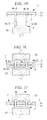
- Figs. 1 are explanation drawings illustrating the repairing method for composite material according to the first embodiment of the present invention.
- Fig. 1A is a top view illustrating composite material in which holes are formed in a delamination generated between layers of the composite material
- Fig. 1B is a cross sectional view taken along line A-A in Fig. 1A
- Fig. 1A to Fig. 1F are explanation drawings illustrating the repairing method for the delamination between the layers of the composite material.
- the composite material 1 is formed by laminating layers 1a, 1b of plural (for example, two) composite materials. Each of the layers 1a, 1b of the composite material is completely hardened.
- a delamination 3 is generated between the layer 1a and the layer 1b of the composite material completely hardened.
- the repairing method for the delamination 3 generated between the layers 1a, 1b of the composite material is carried out such that holes 4 are penetrated in the layer 1a and the layer 1b of the composite material completely hardened, and a staple (joining member) 6 described later is so inserted into the holes 4 as to join the delamination.
- a backing member 50 is disposed on a back side of the composite material where the delamination 3 exists between the layers 1a, 1b.
- the backing member 50 serves for preventing burrs from being generated when the holes 4 are drilled in the layer 1a and the layer 1b of the composite material.
- the holes 4 are drilled in the layers 1a, 1b of the composite material disposed on the backing member 50 downward from the top side by use of a drill 51 having a minute diameter (for example, 1.0 mm).
- the holes 4 are so provided as to be penetrated through the delamination 3 formed between the layer 1a and the layer 1b of the composite material.
- the holes 4 are drilled at plural (for example, two) positions in an area of the delamination 3.
- the diameter of the holes 4a, 4b is the same as that of the drill 51.
- adhesive is applied on the inner surface (inner wall) of each hole 4a, 4b, as illustrated in Fig. 1C .
- adhesive is applied on the outer surface of each of two legs 8a, 8b of the staple 6.
- filling material may be used.
- the staple 6 includes the two legs 8a, 8b.
- the staple 6 has a U-letter outer shape, as illustrated in Fig. 1C .
- the staple 6 is formed of material excellent in strength characteristics and capable of being cold-worked, such as beta-titanium, inconel or austenite stainless material.
- Each of the leg 8a, 8b of the staple 6 has a circular cross sectional shape vertical to the axial direction thereof.
- Each of the leg 8a, 8b has a diameter of 0.9 mm, for example, which is slightly smaller than that of the holes 4.
- the legs 8a, 8b of the staple 6 are inserted into the respective holes 4a, 4b upward from the back side, as illustrated in Fig. 1D .
- the staple 6 is disposed on the top surface of the staple pushing tool 52 with the legs 8a, 8b thereof directing upward.
- the staple pushing tool 52 on which the staple 6 is disposed is so pushed upward as to insert the legs 8a, 8b into the respective holes 4a, 4b.
- the end portions 9a, 9b of the legs 8a, 8b inserted through the respective holes 4a, 4b are bent by pushing a staple clinching tool 53 downward from the top side and pushing the staple pushing tool 52 upward from the back side so that the staple 6 is held therebetween, as illustrated in Fig. 1E .
- the bottom surface of the staple clinching tool 53 is recessed upward at a portion that comes in contact with the end portions 9a, 9b of the legs 8a, 8b. This recessed portion bends the end portions 9a, 9b of the legs 8a, 8b so that they oppose each other.
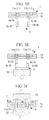
- Figs. 2 illustrate the sealing process in the repairing method for composite material according to the present embodiment
- Fig. 2A is a top view thereof
- Fig. 2B is a cross sectional view taken along line B-B
- Fig. 2C is a bottom view thereof.
- the sealing process is applied on the staple 6 to cover a part thereof in contact with the surface of the layer 1b of the composite material, and to cover on the end portions 9a, 9b of the staple 6 in contact with the surface of the layer 1a of the composite material, with sealing material (sealant) 10.
- the sealing material 10 covers the staple 6 and the layer 1b of the composite material, and the end portions 9a, 9b of the staple 6 and the layer 1a of the composite material, thereby securing water tightness between the staple 6 and the layer 1b of the composite material and also between the end portions 9a, 9b of the staple 6 and the layer 1a of the composite material.
- the repairing method for composite material and the repaired composite material using this method according to the present embodiment achieve the hollowing advantageous effects.
- the holes 4a, 4b are drilled through the delamination 3 generated between the layers 1a, 1b of the composite material, and the staple 6 (joining member) is so inserted into the holes 4a, 4b as to join the delamination 3. Accordingly, even the delamination 3 generated between the layers 1a, 1b of the hardened composite material can be readily joined. As a result, it is possible to reduce the time required for the repairing to join the delamination 3 generated between the layers 1a, 1b of the hardened composite material.
- the end portions 9a, 9b of the staple 6 inserted through the holes 4a, 4b are bent in the bending process. Accordingly, the staple 6 that joins the delamination 3 can be prevented from being loosened. As a result, it is possible to firmly join the delamination 3 generated between the layers 1a, 1b of the hardened composite material.
- the end portions 9a, 9b of the staple 6 that are inserted through the holes 4a, 4b and exposed on the surface of the layer 1a of the composite material, and the staple 6 that is exposed on the surface of the layer 1b of the composite material are covered with the sealing material (sealant) 10. Accordingly, water can be prevented from intruding between the staple 6 and the layers 1a, 1b of the composite material. As a result, it is possible to readily and inexpensively prevent galvanic corrosion from being caused at the time of repairing to join the delamination 3 generated between the layers 1a, 1b of the hardened composite material.
- the repairing method is employed, which is capable of readily repairing the delamination 3 generated between the layers 1a, 1b of the hardened composite material. Accordingly, it is possible to repair the composite material 1 readily in a short time even if it has been hardened.
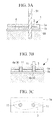
- Figs. 3 are explanation drawings illustrating the repairing method for composite material according to the second embodiment of the present invention.
- Fig. 3A is a cross sectional view illustrating a drilling to form holes through the delamination generated between the layers of the composite material
- Fig. 3B is a cross sectional view illustrating that sleeves are inserted in the holes
- Fig. 3C is a top view of Fig. 3B
- Fig. 3A to Fig. 3G are explanation drawings illustrating the repairing method for the delamination generated between the layers of the composite material.
- Each hole 4 is so formed by use of the drill 51 having a diameter of 1.5 mm, for example, which is slightly greater than that of the first embodiment by the thickness of the sleeve 11, as to penetrate the area of the delamination 3.
- Each sleeve 11 is a hollow cylinder having an outer diameter of 1.5 mm and an inner diameter of 0.9 mm, for example.
- the sleeves 11 have a length that is long enough to penetrate the holes 4a, 4b.
- adhesive is applied on the inner surfaces (inner wall) of the sleeves 11a, 11b respectively inserted into the holes 4a, 4b, and on the outer surfaces of the legs 8a, 8b of the staple 6.
- the legs 8a, 8b of the staple 6 are inserted upward from the back side into the sleeves 11a, 11b on which adhesive is applied.
- the repairing method for composite material and the composite material using this method according to the present embodiment achieve the following advantageous effects.
- the sleeves 11a, 11b are inserted into the holes 4a, 4b formed through the delamination 3, and after this insertion of the sleeves 11a 11b, the legs 8a, 8b of the staple (joining member) 6 are inserted through the sleeves 11a, 11b. Accordingly, the inner surface of the holes 4a, 4b can be prevented from being damaged, which may be caused if the legs 8a, 8b of the staple 6 are directly inserted through the holes 4a, 4b, and thereafter they are bent. As a result, it is possible to prevent a further delamination from progressing, resulted from damage caused on the holes 4a, 4b.
- the sleeves 11a, 11b are inserted into the holes 4a, 4b, but the present invention is not limited to this.
- Protective plates may be provided between the staple 6 and the layer 1b of the composite material and between the end portions 9a, 9b of the staple 6 and the layer 1a of the composite material, respectively, in addition to the insertion of the sleeves 11a, 11b into the holes 4a, 4b.
- Figs. 4 illustrate a modified example of the repairing method for composite material according to the second embodiment of the present invention.
- Figs. 4 illustrate that the protective plates are held between the respective layers of the composite material and the staple
- Fig. 4A is a top view thereof
- Fig. 4B is a cross sectional view taken along line D-D in Fig. 4A .
- the protective plate (galvanic corrosion resistance material) 12a is held between the surface of the layer 1a of the composite material and the end portions 9a, 9b of the staple 6.
- the protective plate (galvanic corrosion resistance material) 12b is also held between the surface of the layer 1b of the composite material and the staple 6.
- the protective plates 12a, 12b are made of galvanic corrosion resistance material.
- the protective plates 12a, 12b are provide with holes corresponding to the holes 4a, 4b formed through the layers 1a, 1b of the composite material.
- the protective plates 12a, 12b are disposed on the surfaces of the respective layers 1a, 1b of the composite material after the sleeves 11a, 11b are inserted into the holes 4a, 4b. After the protective plates 12a, 12b are disposed on the surfaces of the layers 1a, 1b of the composite material, the legs 8a, 8b of the staple 6 are inserted through the protective plates 12a, 12b, and then through the holes 4a, 4b.
- the above described modified example achieves the following advantageous effects.
- the protective plates (galvanic corrosion resistance material) 12a, 12b are provided between the layers 1a, 1b of the hardened composite material and the staple (joining member) 6. Accordingly, galvanic corrosion can be prevented from occurring when the staple 6 comes in contact with the layers 1a, 1b of the composite material. As a result, it is possible to prevent the staple 6 from deteriorating, resulted from the galvanic corrosion after the delamination (not shown) generated the layers 1a, 1b of the hardened composite material is repaired.
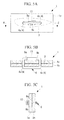
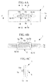
- Figs. 5 are explanation drawings illustrating the repairing method for composite material according to the third embodiment of the present invention.
- Figs. 5 illustrate that both the end portions of the staple are crimped with a crimping sleeve
- Fig. 5A is a top view thereof
- Fig. 5B is a cross sectional view taken along line E-E in Fig. 5A
- Fig. 5C is a side view thereof.
- the end portions 9a, 9b of the staple 6 that are bent are inserted into the crimping sleeve (crimping member) 13 from the respective opposite sides.
- the crimping sleeve 13 is a hollow metal cylinder having an inner diameter great enough to pass the end portions 9a, 9b of the staple 6 therethrough. Force is applied onto the outer side of the crimping sleeve 13 in which the end portions 9a, 9b of the staple 6 are inserted.
- the cross sectional shape of the crimping sleeve 13 is deformed into a quadrilateral shape, as illustrated in Fig. 5C . Therefore, the crimping sleeve 13 is squashed so that the end portions 9a, 9b of the staple 6 inserted in the crimping sleeve 13 are fixed thereinside.
- the repairing method for composite material and the composite material using this method according to the present embodiment achieve the following advantageous effects.
- the end portions 9a, 9b of the staple (joining member) 6 that are inserted through the holes 4a, 4b are crimped with the crimping sleeve (crimping member) 13. Accordingly, the staple 6 that joins the delamination 3 can be prevented from becoming loose, compared to the case without using the crimping sleeve 13. As a result, it is possible to more firmly join the delamination 3 generated between the layers 1a, 1b of the hardened composite material.
- Figs. 6 are explanation drawings illustrating a first modified example of the repairing method for composite material according to the third embodiment of the present invention.
- Figs. 6 illustrate that the end portions of the staple are hooked to the hook fitting
- Fig. 6A is a top view thereof
- Fig. 6B is a cross sectional view taken along line F-F in Fig. 6A
- Fig. 6C is a cross sectional view taken along line G-G in Fig. 6A
- Fig. 6D is a cross sectional view taken along line H-H in Fig. 6A .
- the hook fitting (constraining member) 14 is stuck on the surface of the layer 1a of the hardened composite material.
- the end portions 9a, 9b of the staple (joining member) 6 that are bent are hooked to respective hook portions 14a, 14b of the hook fitting 14.
- the end portions 9a, 9b hooked to the respective hook portions 14a, 14b are bent to opposite sides relative to respective free ends (described later) of the book portions 14a, 14b. Specifically, the end portion 9a passing through the hook portion 14a is bent toward the upper side of the drawing surface, and the end portion 9b passing through the hook portion 14b is bent toward the lower side of the drawing surface, as illustrated in Fig. 6A .
- the hook fitting 14 include a couple of the hook portions 14a, 14b and a hook fitting base 14c.
- the hook fitting base 14c has a rectangular shape.
- the hook fitting base 14c is disposed in the longitudinal direction of the delamination 3.
- the couple of the hook portions 14a, 14b are provided on the top surface of the hook fitting base 14c.
- the hook portions 14a, 14b are disposed vertically relative to the longitudinal direction of the hook fitting base 14c.
- One end of each of the hook portions 14a, 14b is fixed to the hook fitting base 14c, and the other end thereof is a free end, as illustrated in Fig. 6C and Fig. 6D .
- the free ends of the couple of the hook portions 14a, 14b are so disposed as to be oriented in the opposite direction from each other.
- Figs. 7 are explanation drawings illustrating a second modified example of the repairing method for composite material according to the third embodiment of the present invention.
- Figs. 7 illustrate that the end portions of the staple are crimped without being bent by means of the crimping sleeve
- Fig. 7A is a top view thereof
- Fig. 7B is a cross sectional view taken along line I-I in Fig. 7A .
- the crimping sleeves (crimping member) 15 are provided at the respective end portions 9a, 9b of the staple 6 inserted through the respective holes 4a, 4b without being bent.
- Each of the crimping sleeves 15a, 15b is a metal cylinder. Force is applied onto the outer side of each of the crimping sleeves 15a, 15b so as to crimp the end portions 9a, 9b.
- the joining member is the staple 6 having a U-letter outer shape, but this may be liner pins that are inserted through the holes 4a, 4b, and both ends of each linear pin may be crimped.
- Figs. 8 are explanation drawings illustrating a third modified example of the repairing method for composite material according to the third embodiment of the present invention.
- Each left section of Figs. 8 illustrates that both the ends of the pin through the hole are crimped without being bent
- each right section of Figs. 8 illustrates that both the ends of the pin through the hole are bent after they are crimped
- Fig. 8A is a top view thereof
- Fig. 8B is a cross sectional view taken along line J-J in Fig. 8A
- Fig. 8C is a bottom view thereof.
- the respective liner pins (joining member) 16 are inserted through the respective holes 4a, 4b.
- each end portion of the pin 16a inserted through the hole 4a is provided with the crimping sleeve (crimping member) 15.
- each end portion of the pin 16b inserted through the hole 4b is provided with the crimping sleeve 15, and each end portion of the pin 16b inserted through the crimping sleeve 15 is bent.
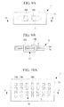
- Figs. 9 are explanation drawings illustrating the repairing method for composite material according to the fourth embodiment of the present invention.
- Figs. 9 illustrate that the joining is carried out by use of the staple having legs each of which has a quadrilateral cross sectional shape as the joining member
- Fig. 9A is a top view thereof
- Fig. 9B is a cross sectional view taken along line K-K in Fig. 9A .
- Each of the legs 18a, 18b of the staple 17 has a quadrilateral cross sectional shape vertical to the axial direction thereof.
- the delamination 3 is joined by use of the staple (joining member) 17 having the legs 18a, 18b each of which has a quadrilateral cross sectional shape vertical to the axial direction thereof. Accordingly, strength to join the delamination 3 can be enhanced. As a result, it is possible to more firmly join the delamination 3 generated between the layers 1a, 1b of the hardened composite material.
- Figs. 10 are explanation drawings illustrating the repairing method for composite material according to the fifth embodiment of the present invention.
- Figs. 10 illustrate that the joining is carried out by use of the staple having many legs each of which has a quadrilateral cross sectional shape
- Fig. 10A is a top view thereof
- Fig. 10B is a cross sectional view taken along line L-L in Fig. 10A
- Fig. 10C is a bottom view thereof
- Fig. 10D is a side view thereof.
- Each staple 19 is disposed with its longitudinal direction along longitudinal direction of the delamination 3.
- the two staples 19 are so disposed as to be parallel to each other.
- Each staple 19 includes a staple base 19a and plural (for example, fourteen) legs 19b.
- Each staple base 19a has a rectangular shape long enough to cover the longitudinal direction of the delamination 3.
- Each staple base 19a is provided with the legs 19b in two rows, in each of which the legs 19b are aligned at an equal interval in between in the longitudinal direction thereof.
- Each staple base 19a has seven legs 19b in each row, for example.
- Each leg 19b has a quadrilateral cross sectional shape vertical to its axial direction.
- the delamination 3 is joined by use of the staple (joining member) 19 having fourteen (plural) legs 19b. Accordingly, it is possible to more firmly join the delamination 3 generated between the layers 1a, 1b of the hardened composite material.
- the staple base 19a becomes firm, its redundancy can be enhanced, compared to the case in which the staples 19 are disposed randomly. If the staple pushing member (not illustrated) and the staple clinching member (not illustrated) provided dedicated to the staple 19, the attachment of the staple 19 can be done at a time, thereby to reduce the operation time.
- the staple base 19a may have a hollow thereinside. Accordingly, it is possible to reduce the weight of the staple 19.
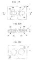
- Figs. 11 are explanation drawings illustrating the repairing method for composite material according to the sixth embodiment of the present invention.
- Figs. 11 illustrate that the joining is carried out by use of the staple having four legs each of which has a quadrilateral cross sectional shape and is provided on each side of the staple
- Fig. 11A is a top view thereof
- Fig. 11B is a cross sectional view taken along line M-M in Fig. 11A
- Fig. 11C is a bottom view thereof.
- a couple of the staples (joining member) 20 may be provided.
- Each staple 20 is disposed adjacent to each other.
- Each staple 20 has a size large enough to cover the delamination 3 with the couple of the staples 20 disposed adjacent to each other.
- the staple 20 includes the staple base 20a and four legs 20b.
- the staple base 20a has a square shape in the bottom view, as illustrated in Fig. 11C .
- Each leg 20b is provided on each side of the staple base 20a.
- Each leg 20b has a rectangular (quadrilateral) cross sectional shape vertical to the axial direction thereof.
- Each opposite leg 20b is so bent as to oppose each other, thereby joining the delamination 3.
- the staple 20 is configured such that each of the four legs 20b having a rectangular (quadrilateral) cross sectional shape vertical to the axial direction thereof is provided on each side of the staple base 20a, and such configured staple 20 is used as the joining member. Accordingly, the delamination 3 generated between the layers 1a, 1b of the hardened composite material can be bonded more firmly since the joining of the delamination 3 is held by the legs 20b in two directions vertical to each other at a time.
- Figs. 12 are explanation drawings illustrating the repairing method for composite material according to the seventh embodiment of the present invention.
- Each right section of Figs. 12 illustrates that the blind rivet is inserted through a hole
- each left section of Figs. 12 illustrates that the joining is carried out by use of the blind rivet
- Fig. 12A is a top view thereof.
- Fig. 12B is a cross sectional view taken along line N-N in Fig. 12A
- Fig. 12C is a bottom view thereof.
- a protective member (galvanic corrosion resistance material) 12 is provided on the surface of the layer 1b of the composite material.
- the blind rivets (joining member) 21 are inserted through the respective holes 4a, 4b with the protective member 12 held between the blind rivets 21 and the layer 1b by use of a riveter (not illustrated).
- a riveter By handling the riveter, a sleeve with a flange 21a of the blind rivet 21, described later, is deformed and a mandrel 21b is cut off at the middle thereof. Accordingly, the delamination 3 generated between the layers 1a, 1b of the hardened composite material is joined with the blind rivets 21.
- Each blind rivet 21 includes the sleeve with the flange 21a and the mandrel 21b inserted through the sleeve with the flange 21a.
- the blind rivet 21 is inserted through the hole 4b in such a manner that the sleeve with the flange 21a comes in contact at its flange portion with the protective member 12 by handling the riveter, as illustrated in the right section of Fig. 12B .
- Each of the blind rivets 21 inserted through the respective holes 4a, 4b is deformed at the tip end of the sleeve with the flange 21a on the surface of the layer 1a of the composite material by handling the riveter so as to pull back the mandrel 21b, as illustrated in the left section of Fig. 12B .
- the mandrel 21b is cut off in the vicinity of the flange of the sleeve with the flange 21a (in the vicinity of the surface of the layer 1b of the composite material).
- the crimping operation with the blind rivets 21 is completed.
- the repairing method for composite material and the composite material using this method according to the present embodiment achieve the following advantageous effects.
- the blind rivets 21 are used as the joining member.
- the blind rivets 21 can be inserted through the holes 4a, 4b, and can also be crimped. Accordingly, the delamination 3 can be readily joined, compared to the case of using the staple (not illustrated). As a result, it is possible to reduce the repairing time for the delamination 3 generated between the layers 1a, 1b of the hardened composite material.
- Figs. 13 are explanation drawings illustrating the repairing method for composite material according to the eighth embodiment of the present invention.
- Figs. 13 illustrate the staple whose surface is coated with coating material
- Fig. 13A is a longitudinal sectional view thereof
- Fig. 13B is a cross sectional view of the legs of the staple.
- the staple (joining member) 22 includes a core 22a made of material excellent in strength characteristics and capable of being cold-worked, and coating material (surface coating) 22b with which the surface of the core 22a is coated.
- the surface of the core 22a is coated with the coating material 22b for (galvanic corrosion prevention.
- the repairing method for composite material and the composite material using this method according to the present embodiment achieve the following advantageous effects.
- the staple (joining member) 22 coated with the coating material (surface coating) 22b for galvanic corrosion prevention is used. Accordingly, occurrence of the galvanic corrosion can be prevented without providing sleeves (not illustrated). As a result, it is possible to reduce the repairing time for the delamination (not illustrated) generated between the layers of the hardened composite material (not illustrated), and prevent the staple 22 from deteriorating due to the galvanic corrosion after the repairing.
- the coating material 22b is coated for the sake of preventing galvanic corrosion, but the present invention is not limited to this, and the coating material 22b may be material for use in conductive processing or insulation processing.
- Figs. 14 are explanation drawings illustrating the repairing method for composite material according to the ninth embodiment of the present invention.
- Figs. 14 illustrate the staple made of shape memory alloy
- Fig. 14A illustrates a state of the staple at a predetermined temperature or below
- Fig. 14B illustrates a state of the staple at a predetermined temperature or above.
- the staple (joining member) 23 is made of shape memory alloy.
- the shape memory alloy may include titanium nickel alloy, for example.
- the staple 23 has end portions 23a, 23b both of which linearly extend upward at a predetermined temperature or below, as illustrated in Fig. 14A .
- the staple 23 is heat-treated so that both the end portions 23a, 23b thereof become bent toward each other at a predetermined temperature or above, as illustrated in Fig. 14B .
- Fig. 15 is a load-elongation diagram of the shape memory alloy.
- the horizontal axis shows elongation and the vertical axis shows load in Fig. 15 .
- Figs. 16 are schematic drawings of atoms of the shape memory alloy, and Fig. 16(A) illustrates a state thereof at a lower temperature, and Fig. 16(B) illustrates a state thereof at a higher temperature.
- the staple 23 see Figs. 14
- the staple 23 made of the shape memory alloy deforms the end portions 23a, 23b thereof to linearly extend upward at a predetermined temperature or below, distortion occurs in the bond between atoms as illustrated in Fig. 16 (A) .
- each atom included in the staple 23 returns to a memorized state, as illustrated in Fig. 16 (B) .
- the end portions 23a, 23b of the staple 23 come into a state in which they are bent.
- the repairing method for composite material and the composite material using this method according to the present embodiment achieve the following advantageous effects.
- Shape memory alloy is used as material for the staple (joining member) 23. Accordingly, the staple 23 can be formed into a predetermined shape depending on the temperature change. As a result, it is possible to readily in a short time carry out the repairing to bond the delamination between the layers of the hardened composite material (not illustrated) by inserting the staple 23 through the holes (not illustrated) and heating the staple to a predetermined temperature.
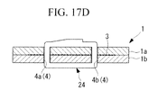
- Figs. 17 are explanation drawings illustrating the repairing method for composite material according to the tenth embodiment of the present invention.
- Figs. 17 illustrate that the end portions of the staple made of the reinforced fiber are cured to each other
- Fig. 17A is a top view thereof
- Fig. 17B is a side view thereof
- Fig. 17C is a cross sectional view taken along line X-X in Fig. 17A
- Fig. 17D illustrates that the end portions of the staple illustrated in Fig. 17C are joined to each other.
- the staple (joining member) 24 is made of resin, for example, the reinforced fiber impregnated with resin such as thermoplastics resin.
- the end portions 24a, 24b of the staple 24 inserted through the holes 4a, 4b are pressed downward from the top to each other as illustrated in Fig. 17C . Thereafter, the staple 24 is maintained so that the end portions 24a, 24b thereof are encouraged to be cured, and then are completely hardened and joined to each other, as illustrated in Fig. 17D .
- the repairing method for composite material and the composite material using this method according to the present embodiment achieve the following advantageous effects.
- Reinforced fiber impregnated with thermoplastics resin is used for the staple (joining member) 24.
- this reinforced fiber impregnated with thermoplastics resin can be cured and joined at room temperature. Accordingly, it is possible to more firmly bond the delamination 3 generated between the layers 1a, 1b of the hardened composite material. It is also possible to prevent the composite material and the joining member from deteriorating due to galvanic corrosion, which occurs in the case of using the staple of metal.
- the staple 24 is made of the reinforced fiber impregnated with thermoplastics resin, but the present invention is not limited to this, and reinforced fiber impregnated with thermosetting resin may also be used.
- the thermosetting resin the reinforced fiber and resin are heated at a high temperature so as to be hardened.
- the present invention is not limited to this, for example, after the end portions 24a, 24b are bent, they are stuck on the surface of the layer 1a of the composite material, and then are pressed and maintained so that the end portions 24a, 24b and the layer 1a of the composite material are hardened and joined at a time. In this case, firmer joining can be secured because the end portions 24a, 24b are fixed to the surface of the layer 1a, compared to the case of merely joining the bent end portions 24a, 24b.
- end portions 24a, 24b of the staple 24 made of the composite fiber are bent and cured, these hardened end portions 24a, 24b may be stuck with adhesive onto the surface of the layer 1a of the composite material.
- the sticking process is additionally required, firmer joining can be secured, compared to the case of simply bending and joining the end portions 24a, 24b.
Landscapes
- Engineering & Computer Science (AREA)
- Mechanical Engineering (AREA)
- Manufacturing & Machinery (AREA)
- Transportation (AREA)
- Aviation & Aerospace Engineering (AREA)
- Lining Or Joining Of Plastics Or The Like (AREA)
- Connection Of Plates (AREA)
Abstract
Description
- The present invention relates to a repairing method for composite material for use as structural material of an aircraft or the like and a repaired composite material using this method, and in particular to join a delamination generated between layers of composite material that has been hardened.
- In general, examples of a repairing method for a delamination between layers of composite material for use in aircraft structural material or the like include a resin injection method as described in
Patent Literature 1, a gap filling method using repairing material after trimming as described in Patent Literature 2, a pin or staple fitting method described inPatent Literature -
- {PTL 1}
Japanese Unexamined Patent Application, Publication No.Hei 07-137154 - {PTL 2}
The Publication of Japanese Patent No.2541620 - {PTL 3}
Japanese Unexamined Patent Application, Publication No.Hei 03-297629 - {PTL 4}
Japanese Unexamined Patent Application, Publication No.Hei 02-74325 - {PTL 5}
Japanese Unexamined Patent Application, Publication No.Hei 03-286841 - However, the invention described in
Patent Literature 1 has a difficulty that a resin injection cannot be carried out if a delamination generated between layers of composite material is slight. The invention ofPatent Literature 1 and Patent Literature 2 have difficulties in controlling each process of cleaning, drying and bonding, so that time required for a repairing operation becomes increased.
The invention described inPatent Literature 3 has a difficulty that the method is limited to the case of using thermoplastics composite material, and cannot be applicable to repairing for thermosetting composite material that cannot be softened by re-heating once the material has been hardened.
The inventions described inPatent Literature 4 and Patent Literature 5 have a difficulty that the methods are limited to a stage where layers of composite material are still soft before they become cured, and cannot be applicable to repairing of composite material completely hardened. - The present invention has been made in the light of the above facts, and has an object to provide a repairing method for composite material and a repaired composite material using this method, which are capable of readily repairing, in a short time, a delamination generated between layers of hardened composite material.
- In order to solve the above mentioned problems, the repairing method for composite material and the repaired composite material using this method according to the present invention provide the following solutions.
According to the repairing method for composite material of the first aspect of the present invention, a hole is drilled through a delamination generated between layers of hardened composite material, and a joining member is inserted into the hole so as to join the delamination gap. - The hole is formed through the delamination generated between the layers of the composite material, and the joining member is so inserted into the hole as to join the delamination. Accordingly, even the delamination generated between the layers of the hardened composite material can be readily bonded. As a result, it is possible to reduce the time required for the repairing the delamination generated between the layers of the hardened composite material.
- According to the repairing method for composite material of the above described aspect, sleeve may be inserted into the hole, and the joining member may be inserted through the sleeve.
- The sleeve is inserted into the hole formed through the delamination, and then, the joining member is inserted through the sleeve. Accordingly, the inner surface of the hole can be prevented from being damaged at the time of inserting the joining member through the hole and bending it. As a result, it is possible to prevent a further delamination from progressing, resulted from damage caused on the hole.
Further, it is possible to present galvanic corrosion in such a combination of materials that cause deterioration of the galvanic corrosion resistance when the joining member directly comes in contact with the composite material. - According to the repairing method for composite material of the above described aspect, a bending process may be applied to an end portion of the joining member that is inserted through the hole.
- The end portion of the joining member inserted through the hole is bent in the bending process. Accordingly the joining member that joins the delamination can be prevented from becoming loose. As a result, it is possible to firmly join the delamination between the layers of the hardened composite material.
- According to the repairing method for composite material of the above described aspect, an end portion of the joining member that is inserted through the hole may be crimped witch a crimping member.
- The end portion of the joining member that is inserted through the hole is crimped with the crimping member. Accordingly, the joining member that joins the delamination can be prevented from becoming loose, compared to the case without using the crimping member. As a result, it is possible to more firmly, join the delamination generated between the layers of the hardened composite material.
- According to the repairing method for composite material of the above described aspect, an end portion of the joining member that is inserted through the hole may be covered with a sealant.
- The end portion of the joining member that is inserted through the hole and exposed on the surface of the layer of the composite material is covered with the sealant. Accordingly, water can be prevented from intruding between the joining member and the layers of the composite material. As a result, it is possible to readily and inexpensively prevent galvanic corrosion from being caused at the time of the repairing to join the delamination generated between the layers of the hardened composite material.
- According to the repairing method for composite material of the above described aspect, a galvanic corrosion resistance material may be provided between the joining member and the layers of the composite material.
- The galvanic corrosion resistance material is provided between the layers of the composite material and the joining member. Accordingly, the galvanic corrosion can be prevented from occurring when the joining member comes in contact with the layers of the composite material. As a result, it is possible to prevent the joining member from deteriorating, resulted from galvanic corrosion after the repairing of the delamination generated between the layers of the hardened composite material.
- According to the repairing method for composite material of the above described aspect, the joining member may be in a quadrilateral cross sectional shape.
- The delamination is joined by use of the joining member in a quadrilateral cross sectional shape. Accordingly, strength to join the delamination can be enhanced. As a result, it is possible to more firmly join the delamination generated between the layers of the hardened composite material.
- According to the repairing method for composite material of the above described aspect, the joining member may include a staple having plural legs.
- The delamination is joined by use of the staple having plural legs. Accordingly, it is possible to more firmly join the delamination generated between the Layers of the composite material.
Further, there is no need to join the delamination by use of plural staples, thereby reducing the working time for joining the delamination. - According to the repairing method for composite material of the above described aspect, the staple may include four legs, and each of the legs may be provided on each side of the staple in a quadrilateral shape.
- The staple is used as the joining member, which is configured such that each of the legs having a quadrilateral cross sectional shape is provided on each side of the staple body. Accordingly, the joining of the delamination generated between the layers of the hardened composite material can be firmer since the joining of the delamination is held by the legs in two directions vertical to each other at a time.
- According to the repairing method for composite material of the above described aspect, the joining member may be a staple having legs made of reinforced fiber impregnated with thermoplastics resin or thermosetting resin.
- The staple having the legs made of reinforced fiber impregnated with resin is used and the resin thereof is made to be hardened, thereby bonding the end portions of the legs to each other. Thus, the staple becomes into a loop, so that the delamination gap between the layers of the composite material can be joined more firmly.
There is no need to consider galvanic corrosion, which occurs in the case of using the staple of metal, so that the composite material and the joining member can be prevented from deteriorating. - According to the repairing method for composite material of the above described aspect, the joining member may be a blind rivet.
- The blind rivet is used as the joining member. Thus, the blind rivet can be inserted through the hole and can be crimped. Accordingly, the joining can be readily carried out, compared to the case of using the staple. As a result, it is possible to reduce the repairing time for the delamination generated between the layers of the hardened composite material.
- According to the repairing method for composite material of the above described aspect, the joining member may be provided with surface coating for galvanic corrosion prevention.
- The joining member provided with the surface coating for galvanic corrosion prevention is used. Accordingly, occurrence of the galvanic corrosion can be prevented without providing the sleeve or the like. As a result, it is possible to readily repair the delamination generated between the layers of the composite material, and also reduce the repairing time therefor.
Further, since no sleeve is provided, it is possible to reduce the diameter of the hole drilled in the composite material. Thus, there is no need to break the fiber of the composite material through the drilling. Accordingly, it is possible to facilitate the drilling, and reduce influence of deterioration of strength in fiber of the composite material. - According to the repairing method for composite material of the above described aspect, the joining member may be made of shape memory alloy.
- Shape memory alloy is used as material for the joining member. Accordingly, the joining member can be formed into a predetermined shape depending on the temperature change. As a result, it is possible to readily in a short time carry out the repairing to join the delamination between the layers of the hardened composite material by setting a predetermined temperature.
- According to the composite material of the above described aspect, the composite material may be repaired by the repairing method for composite material according to any one of the descriptions in the above described aspect.
- The repairing method capable of readily repairing the delamination generated between the layers of the hardened composite material is used. Accordingly, a short time repair is possible to even for the hardened composite material.
- The hole is drilled through the delamination gap generated between the layers of the composite material, and the joining member is so inserted into the hole as to join the delamination. Accordingly, even the delamination generated between the layers of the hardened composite material can be readily joined. As a result, it is possible to reduce the time required for repairing the delamination generated between the layers of the hardened composite material.
-
- {
Fig. 1A} Fig. 1A is an explanation drawing illustrating the repairing method for composite material according to the first embodiment of the present invention, and is a top view of the composite material in which holes are drilled in the delaminated area generated between the layers of the composite material. - {
Fig. 1B} Fig. 1B is a cross sectional view taken along line A-A inFig. 1A . - {
Fig. 1C} Fig. 1C is an explanation drawing illustrating the repairing method for the delamination generated between layers of the composite material. - {
Fig. 1D} Fig. 1D is an explanation drawing illustrating the repairing method for the delamination generated between layers of the composite material. - {
Fig. 1E} Fig. 1E is an explanation drawing illustrating the repairing method for the delamination generated between layers of the composite material. - {
Fig. 1F} Fig. 1F is an explanation drawing illustrating the repairing method for the delamination generated between layers of the composite material. - {
Fig. 2A} Fig. 2A is a top view for explaining a sealing process retarding the repairing method for composite material according to the first embodiment of the present invention. - {
Fig. 2B} Fig. 2B is a cross sectional view taken along line B-B inFig. 2A . - {
Fig. 2C} Fig. 2C is a bottom view ofFig. 2A . - {
Fig. 3A} Fig. 3A is an explanation drawing illustrating the repairing method for composite material according to the second embodiment of the present invention, and is a cross sectional view of providing a drilling, in the delaminated area generated between the layers of the composite material. - {
Fig. 3B} Fig. 3B is a cross sectional view illustrating that sleeves are inserted into the holes illustrated inFig. 3A . - {
Fig. 3C} Fig. 3C is a top view ofFig. 3B . - {
Fig. 3D} Fig. 3D is an explanation drawing illustrating the repairing method for the delamination generated between layers of the composite material. - {
Fig. 3E} Fig. 3E is an explanation drawing illustrating the repairing method for the delamination generated between layers of the composite material. - {
Fig. 3F} Fig. 3F is an explanation drawing illustrating the repairing method for the delamination generated between layers of the composite material. - {
Fig. 3G} Fig. 3G is an explanation drawing illustrating the repairing method for the delamination generated between layers of the composite material. - {
Fig. 4A} Fig. 4A is an explanation drawing of a modified example of the repairing method for composite material according to the second embodiment of the present invention, and is a top view illustrating that protective plates are held between the layers of the composite material and the staple. - {
Fig. 4B} Fig. 4B is a cross sectional view taken along line D-D inFig. 4A . - {
Fig. 5A} Fig. 5A is an explanation drawing illustrating the repairing method for composite material according to the third embodiment of the present invention, and is a top view illustrating that both the end portions of the staple are crimped with a crimping sleeve. - {
Fig. 5B} Fig. 5B is a cross sectional view taken along line E-E inFig. 5A . - {
Fig. 5C} Fig. 5C is a side view ofFig. 5A . - {
Fig. 6A} Fig. 6A is an explanation drawing illustrating a first modified example of the repairing method for composite material according to the third embodiment of the present invention, and is a top view illustrating that the end portions of the staple are hooked to the hook fitting. - {
Fig. 6B} Fig. 6B is a cross sectional view taken along line F-F inFig. 6A . - {
Fig. 6C} Fig. 6C is a cross sectional view taken along line G-G inFig. 6A . - {
Fig. 6D} Fig. 6D is a cross sectional view taken along line H-H inFig. 6A . - {
Fig. 7A} Fig. 7A is an explanation drawing illustrating a second modified example of the repairing method for composite material according to the third embodiment of the present invention, and is a top view illustrating that the end portions of the staple are crimped without being bent by means of a crimping sleeve. - {
Fig. 7B} Fig. 7B is a cross sectional view taken along line I-I inFig. 7A . - {
Fig. 8A} Fig. 8A is an explanation drawing illustrating a third modified example of the repairing method for composite material according to the third embodiment of the present invention, and is a top view of a left section ofFig. 8A illustrating that both the ends of the pin inserted through the hole are crimped without being bent, and a right section ofFig. 8A thereof illustrating that both the ends of the pin inserted through the hole are bent after they are crimped. - {
Fig. 8B} Fig. 8B is a cross sectional view taken along line J-J inFig. 8A . - {
Fig. 8C} Fig. 8C is a bottom view ofFig. 8A . - {
Fig. 9A} Fig. 9A is an explanation drawing illustrating the repairing method for composite material according to the fourth embodiment of the present invention, and is a top view illustrating that the joining is carried out by use of the staple having legs each of which has a quadrilateral cross sectional shape as the joining member. - {
Fig. 9B} Fig. 9B is a cross sectional view taken along line K-K inFig. 9A . - {
Fig. 10A} Fig. 10A is an explanation drawing illustrating the repairing method for composite material according to the fifth embodiment of the present invention, and is a top view illustrating that the joining is carried out by use of the staple having many legs each of which has a quadrilateral cross sectional shape. - {
Fig. 10B} Fig. 10B is a cross sectional view taken along line L-L inFig. 10A . - {
Fig. 10C} Fig. 10C is a bottom view ofFig. 10A . - {
Fig. 10D} Fig. 10D is a side view ofFig. 10A . - {
Fig. 11A} Fig. 11A an explanation drawing illustrating the repairing method for composite material according to the sixth embodiment of the present invention, and is a top view illustrating that the joining is carried out by use of the staple having four legs each of which has a quadrilateral cross sectional shape and is provided on each side of the staple. - {
Fig. 11B} Fig. 11B is a cross sectional view taken along line M-M inFig. 11A . - {
Fig. 11C} Fig. 11C is a bottom view ofFig. 11A . - {
Fig. 12A} Fig. 12A is an explanation drawing illustrating the repairing method for composite material according to the seventh embodiment of the present invention, and is a top view of a right section ofFig. 12A illustrating that the blind rivet inserted through a hole, and a left section ofFigs. 12A thereof illustrating that the joining is carried out by use of the blind rivet. - {
Fig. 12B} Fig. 12B is a cross sectional view taken along line N-N inFig. 12A . - {
Fig. 12C} Fig. 12C is a bottom view ofFig. 12A . - {
Fig. 13A} Fig. 13A is an explanation drawing illustrating the repairing method for composite material according to the eighth embodiment of the present invention, and is a longitudinal sectional view illustrating the staple whose surface is coated with coating material. - {
Fig. 13B} Fig. 13B is a cross sectional view of the legs of the staple illustrated inFig. 13A . - {
Fig. 14A} Fig. 14A is an explanation drawing illustrating the repairing method for composite material according to the ninth embodiment of the present invention, and is a longitudinal sectional view illustrating a state of the staple made of shape memory alloy at a predetermined temperature or below. - {
Fig. 14B} Fig. 14B is a longitudinal sectional view illustrating a state of the staple illustrated inFig. 14A at a predetermined temperature or above. - {
Fig. 15} Fig. 15 is a load-elongation diagram of the shape memory alloy. - {
Fig. 16} Fig. 16 is a schematic drawing of atoms of shape memory alloy. - {
Fig. 17A} Fig. 17A is an explanation drawing illustrating the repairing method for composite material according to the tenth embodiment of the present invention, and is a top view illustrating that the end portions of the staple made of the reinforced fiber are cured to each other. - {
Fig. 17B} Fig. 17B is a side view ofFig. 17A . - {
Fig. 17C} Fig. 17C is a cross sectional view taken along line X-X inFig. 17A . - {
Fig. 17D} Fig. 17D illustrates that the end portions of the staple illustrated inFig. 17C are joined to each other. -
Figs. 1 are explanation drawings illustrating the repairing method for composite material according to the first embodiment of the present invention.
Fig. 1A is a top view illustrating composite material in which holes are formed in a delamination generated between layers of the composite material,Fig. 1B is a cross sectional view taken along line A-A inFig. 1A, and Fig. 1A toFig. 1F are explanation drawings illustrating the repairing method for the delamination between the layers of the composite material.
Thecomposite material 1 is formed by laminatinglayers layers delamination 3 is generated between thelayer 1a and thelayer 1b of the composite material completely hardened. The repairing method for thedelamination 3 generated between thelayers layer 1a and thelayer 1b of the composite material completely hardened, and a staple (joining member) 6 described later is so inserted into theholes 4 as to join the delamination. - A backing
member 50 is disposed on a back side of the composite material where thedelamination 3 exists between thelayers member 50 serves for preventing burrs from being generated when theholes 4 are drilled in thelayer 1a and thelayer 1b of the composite material. Theholes 4 are drilled in thelayers member 50 downward from the top side by use of adrill 51 having a minute diameter (for example, 1.0 mm). - The
holes 4 are so provided as to be penetrated through thedelamination 3 formed between thelayer 1a and thelayer 1b of the composite material. Theholes 4 are drilled at plural (for example, two) positions in an area of thedelamination 3. The diameter of theholes drill 51. - After the
holes delamination 3, adhesive is applied on the inner surface (inner wall) of eachhole Fig. 1C . Similarly, adhesive is applied on the outer surface of each of twolegs staple 6. Instead of the adhesive, filling material may be used. - The
staple 6 includes the twolegs staple 6 has a U-letter outer shape, as illustrated inFig. 1C . Thestaple 6 is formed of material excellent in strength characteristics and capable of being cold-worked, such as beta-titanium, inconel or austenite stainless material. Each of theleg staple 6 has a circular cross sectional shape vertical to the axial direction thereof. Each of theleg holes 4. - After the adhesive is applied on the inner surface of each of the
holes legs staple 6, thelegs staple 6 are inserted into therespective holes Fig. 1D . When inserting thestaple 6 into theholes staple 6 is disposed on the top surface of thestaple pushing tool 52 with thelegs staple pushing tool 52 on which thestaple 6 is disposed is so pushed upward as to insert thelegs respective holes - The
end portions legs respective holes staple clinching tool 53 downward from the top side and pushing thestaple pushing tool 52 upward from the back side so that thestaple 6 is held therebetween, as illustrated inFig. 1E . - The bottom surface of the
staple clinching tool 53 is recessed upward at a portion that comes in contact with theend portions legs end portions legs - Force is applied onto the
end portions staple clinching tool 53 and onto thestaple 6 from its back side by thestaple pushing tool 52, so as to bend theend portions Fig. 1F . Through this bending process, thestaple 6 can join thedelamination 3 generated between thelayers - After the
delamination 3 is joined with thestaple 6, a sealing process is applied on thestaple 6 in contact with the surface of thelayers
Figs. 2 illustrate the sealing process in the repairing method for composite material according to the present embodiment,Fig. 2A is a top view thereof,Fig. 2B is a cross sectional view taken along line B-B, andFig. 2C is a bottom view thereof. - The sealing process is applied on the
staple 6 to cover a part thereof in contact with the surface of thelayer 1b of the composite material, and to cover on theend portions staple 6 in contact with the surface of thelayer 1a of the composite material, with sealing material (sealant) 10. - The sealing
material 10 covers thestaple 6 and thelayer 1b of the composite material, and theend portions staple 6 and thelayer 1a of the composite material, thereby securing water tightness between thestaple 6 and thelayer 1b of the composite material and also between theend portions staple 6 and thelayer 1a of the composite material. - As described above, the repairing method for composite material and the repaired composite material using this method according to the present embodiment achieve the hollowing advantageous effects.
Theholes delamination 3 generated between thelayers holes delamination 3. Accordingly, even thedelamination 3 generated between thelayers delamination 3 generated between thelayers - The
end portions staple 6 inserted through theholes staple 6 that joins thedelamination 3 can be prevented from being loosened. As a result, it is possible to firmly join thedelamination 3 generated between thelayers - The
end portions staple 6 that are inserted through theholes layer 1a of the composite material, and thestaple 6 that is exposed on the surface of thelayer 1b of the composite material are covered with the sealing material (sealant) 10. Accordingly, water can be prevented from intruding between thestaple 6 and thelayers delamination 3 generated between thelayers - The repairing method is employed, which is capable of readily repairing the
delamination 3 generated between thelayers composite material 1 readily in a short time even if it has been hardened. - Hereinafter, the second embodiment of the present invention will be explained. The repairing method for composite material and the composite material using this method according to the present embodiment are different from the first embodiment, where there are provided sleeves in the holes, and the others are the same. Thus, same numbers refer to same components and same repairing method in previously described embodiment, thus, descriptions thereof will be omitted.
-
Figs. 3 are explanation drawings illustrating the repairing method for composite material according to the second embodiment of the present invention.
Fig. 3A is a cross sectional view illustrating a drilling to form holes through the delamination generated between the layers of the composite material,Fig. 3B is a cross sectional view illustrating that sleeves are inserted in the holes,Fig. 3C is a top view ofFig. 3B, and Fig. 3A toFig. 3G are explanation drawings illustrating the repairing method for the delamination generated between the layers of the composite material. - Each
hole 4 is so formed by use of thedrill 51 having a diameter of 1.5 mm, for example, which is slightly greater than that of the first embodiment by the thickness of thesleeve 11, as to penetrate the area of thedelamination 3. - The
sleeves 11 are inserted into theholes layers Fig. 3B .
Eachsleeve 11 is a hollow cylinder having an outer diameter of 1.5 mm and an inner diameter of 0.9 mm, for example. Thesleeves 11 have a length that is long enough to penetrate theholes - As illustrated in
Fig. 3D , adhesive is applied on the inner surfaces (inner wall) of thesleeves holes legs staple 6.
As illustrated inFig. 3E , thelegs staple 6 are inserted upward from the back side into thesleeves - As described above, the repairing method for composite material and the composite material using this method according to the present embodiment achieve the following advantageous effects.
Thesleeves holes delamination 3, and after this insertion of thesleeves 11alegs sleeves holes legs staple 6 are directly inserted through theholes holes - Further, it is possible to prevent galvanic corrosion, from occurring in such a combination of materials that cause deterioration of the galvanic corrosion resistance when the
staple 6 comes in contact directly with thecomposite material 1. - In the present embodiment, it has been explained that the
sleeves holes staple 6 and thelayer 1b of the composite material and between theend portions staple 6 and thelayer 1a of the composite material, respectively, in addition to the insertion of thesleeves holes -
Figs. 4 illustrate a modified example of the repairing method for composite material according to the second embodiment of the present invention.Figs. 4 illustrate that the protective plates are held between the respective layers of the composite material and the staple, andFig. 4A is a top view thereof, andFig. 4B is a cross sectional view taken along line D-D inFig. 4A .
The protective plate (galvanic corrosion resistance material) 12a is held between the surface of thelayer 1a of the composite material and theend portions staple 6. The protective plate (galvanic corrosion resistance material) 12b is also held between the surface of thelayer 1b of the composite material and thestaple 6. Theprotective plates protective plates holes layers - The
protective plates respective layers sleeves holes protective plates layers legs staple 6 are inserted through theprotective plates holes - The above described modified example achieves the following advantageous effects.
The protective plates (galvanic corrosion resistance material) 12a, 12b are provided between thelayers staple 6 comes in contact with thelayers staple 6 from deteriorating, resulted from the galvanic corrosion after the delamination (not shown) generated thelayers - Hereinafter, the third embodiment of the present invention will be explained. The repairing method for composite material and the composite material using this method according to the present embodiment are different from the first embodiment, where the end portions are crimped after they are bent, and the others are the same. Thus, same numbers refer to same components and same repairing method in previously described embodiment, thus, descriptions thereof will be omitted.
Figs. 5 are explanation drawings illustrating the repairing method for composite material according to the third embodiment of the present invention.
Figs. 5 illustrate that both the end portions of the staple are crimped with a crimping sleeve,Fig. 5A is a top view thereof,Fig. 5B is a cross sectional view taken along line E-E inFig. 5A, and Fig. 5C is a side view thereof. - The
end portions staple 6 that are bent are inserted into the crimping sleeve (crimping member) 13 from the respective opposite sides. The crimpingsleeve 13 is a hollow metal cylinder having an inner diameter great enough to pass theend portions staple 6 therethrough. Force is applied onto the outer side of the crimpingsleeve 13 in which theend portions staple 6 are inserted. - By applying force onto the outer side of the cramping
sleeve 13, the cross sectional shape of the crimpingsleeve 13 is deformed into a quadrilateral shape, as illustrated inFig. 5C . Therefore, the crimpingsleeve 13 is squashed so that theend portions staple 6 inserted in the crimpingsleeve 13 are fixed thereinside. - As described above, the repairing method for composite material and the composite material using this method according to the present embodiment achieve the following advantageous effects.
Theend portions holes staple 6 that joins thedelamination 3 can be prevented from becoming loose, compared to the case without using the crimpingsleeve 13. As a result, it is possible to more firmly join thedelamination 3 generated between thelayers - In the present embodiment, it has been explained that the
end portions staple 6 inserted through theholes sleeve 13 and are crimped thereinside, but the present invention is not limited to this, and a hook fitting for hooking theend portions staple 6 may be used, instead of using the crimpingsleeve 13. -
Figs. 6 are explanation drawings illustrating a first modified example of the repairing method for composite material according to the third embodiment of the present invention.
Figs. 6 illustrate that the end portions of the staple are hooked to the hook fitting,Fig. 6A is a top view thereof,Fig. 6B is a cross sectional view taken along line F-F inFig. 6A, Fig. 6C is a cross sectional view taken along line G-G inFig. 6A , andFig. 6D is a cross sectional view taken along line H-H inFig. 6A .
The hook fitting (constraining member) 14 is stuck on the surface of thelayer 1a of the hardened composite material. Theend portions respective hook portions - The
end portions respective hook portions book portions end portion 9a passing through thehook portion 14a is bent toward the upper side of the drawing surface, and theend portion 9b passing through thehook portion 14b is bent toward the lower side of the drawing surface, as illustrated inFig. 6A . - The hook fitting 14 include a couple of the
hook portions fitting base 14c. The hookfitting base 14c has a rectangular shape. The hookfitting base 14c is disposed in the longitudinal direction of thedelamination 3. - The couple of the
hook portions fitting base 14c. Thehook portions fitting base 14c. One end of each of thehook portions fitting base 14c, and the other end thereof is a free end, as illustrated inFig. 6C andFig. 6D . The free ends of the couple of thehook portions - In the present embodiment, the end portions of the staple may simply be crimped without being bent.
Figs. 7 are explanation drawings illustrating a second modified example of the repairing method for composite material according to the third embodiment of the present invention.
Figs. 7 illustrate that the end portions of the staple are crimped without being bent by means of the crimping sleeve, andFig. 7A is a top view thereof, andFig. 7B is a cross sectional view taken along line I-I inFig. 7A . - The crimping sleeves (crimping member) 15 are provided at the
respective end portions staple 6 inserted through therespective holes sleeves sleeves end portions - In the present embodiment, it has been explained that the joining member is the
staple 6 having a U-letter outer shape, but this may be liner pins that are inserted through theholes
Figs. 8 are explanation drawings illustrating a third modified example of the repairing method for composite material according to the third embodiment of the present invention.
Each left section ofFigs. 8 illustrates that both the ends of the pin through the hole are crimped without being bent, each right section ofFigs. 8 illustrates that both the ends of the pin through the hole are bent after they are crimped,Fig. 8A is a top view thereof,Fig. 8B is a cross sectional view taken along line J-J inFig. 8A, and Fig. 8C is a bottom view thereof. - The respective liner pins (joining member) 16 are inserted through the
respective holes Fig. 8A , each end portion of thepin 16a inserted through thehole 4a is provided with the crimping sleeve (crimping member) 15. As shown in the right section ofFig. 8A , each end portion of thepin 16b inserted through thehole 4b is provided with the crimpingsleeve 15, and each end portion of thepin 16b inserted through the crimpingsleeve 15 is bent. - Hereinafter, the fourth embodiment of the present invention will be explained. The repairing method for composite material and the composite material using this method according to the present embodiment are different from the first embodiment, where each leg of the staple has a quadrilateral cross sectional shape, and the others are the same. Thus, same numbers refer to same components and same repairing method in previously described embodiment, thus, descriptions thereof will be omitted.
Figs. 9 are explanation drawings illustrating the repairing method for composite material according to the fourth embodiment of the present invention.
Figs. 9 illustrate that the joining is carried out by use of the staple having legs each of which has a quadrilateral cross sectional shape as the joining member,Fig. 9A is a top view thereof, andFig. 9B is a cross sectional view taken along line K-K inFig. 9A .
Each of thelegs - As described above, the repairing method for composite material and the composite material using this method according to the present embodiment achieve the following advantageous effects.
Thedelamination 3 is joined by use of the staple (joining member) 17 having thelegs delamination 3 can be enhanced. As a result, it is possible to more firmly join thedelamination 3 generated between thelayers - Hereinafter, the fifth embodiment of the present invention will be explained. The repairing method for composite material and the composite material using this method according to the present embodiment are different from the first embodiment, where the staple has many legs and each leg thereof has a quadrilateral cross sectional shape, but the others are the same. Thus, same numbers refer to same components and same repairing method in previously described embodiment, thus, descriptions thereof will be omitted.
Figs. 10 are explanation drawings illustrating the repairing method for composite material according to the fifth embodiment of the present invention.
Figs. 10 illustrate that the joining is carried out by use of the staple having many legs each of which has a quadrilateral cross sectional shape,Fig. 10A is a top view thereof,Fig. 10B is a cross sectional view taken along line L-L inFig. 10A ,Fig. 10C is a bottom view thereof, andFig. 10D is a side view thereof. - Plural (for example, two) staples (joining member) 19 are provided. Each
staple 19 is disposed with its longitudinal direction along longitudinal direction of thedelamination 3. The twostaples 19 are so disposed as to be parallel to each other. - Each
staple 19 includes astaple base 19a and plural (for example, fourteen)legs 19b. Eachstaple base 19a has a rectangular shape long enough to cover the longitudinal direction of thedelamination 3. Eachstaple base 19a is provided with thelegs 19b in two rows, in each of which thelegs 19b are aligned at an equal interval in between in the longitudinal direction thereof. Eachstaple base 19a has sevenlegs 19b in each row, for example. Eachleg 19b has a quadrilateral cross sectional shape vertical to its axial direction. - As described above, the repairing method for composite material and the composite material using this method according to the present embodiment achieve the following advantageous effects.
Thedelamination 3 is joined by use of the staple (joining member) 19 having fourteen (plural)legs 19b. Accordingly, it is possible to more firmly join thedelamination 3 generated between thelayers - Since the
staple base 19a becomes firm, its redundancy can be enhanced, compared to the case in which thestaples 19 are disposed randomly.
If the staple pushing member (not illustrated) and the staple clinching member (not illustrated) provided dedicated to thestaple 19, the attachment of the staple 19 can be done at a time, thereby to reduce the operation time. - The
staple base 19a may have a hollow thereinside. Accordingly, it is possible to reduce the weight of thestaple 19. - Hereinafter, the sixth embodiment of the present invention will be explained. The repairing method for composite material and the composite material using this method according to the present embodiment are different from the first embodiment, where each of four legs of the staple has a quadrilateral cross sectional shape and the staple has one leg on each side thereof, but the others are the same. Thus, same numbers refer to same components and same repairing method in the previously described embodiment, thus, descriptions thereof will be omitted.
Figs. 11 are explanation drawings illustrating the repairing method for composite material according to the sixth embodiment of the present invention.
Figs. 11 illustrate that the joining is carried out by use of the staple having four legs each of which has a quadrilateral cross sectional shape and is provided on each side of the staple,Fig. 11A is a top view thereof,Fig. 11B is a cross sectional view taken along line M-M inFig. 11A, and Fig. 11C is a bottom view thereof. - For example, a couple of the staples (joining member) 20 may be provided. Each
staple 20 is disposed adjacent to each other. Eachstaple 20 has a size large enough to cover thedelamination 3 with the couple of thestaples 20 disposed adjacent to each other. - The staple 20 includes the
staple base 20a and fourlegs 20b. Thestaple base 20a has a square shape in the bottom view, as illustrated inFig. 11C . Eachleg 20b is provided on each side of thestaple base 20a. Eachleg 20b has a rectangular (quadrilateral) cross sectional shape vertical to the axial direction thereof. Eachopposite leg 20b is so bent as to oppose each other, thereby joining thedelamination 3. - As described above, the repairing method for composite material and the composite material using this method according to the present embodiment achieve the following advantageous effects.
The staple 20 is configured such that each of the fourlegs 20b having a rectangular (quadrilateral) cross sectional shape vertical to the axial direction thereof is provided on each side of thestaple base 20a, and such configuredstaple 20 is used as the joining member. Accordingly, thedelamination 3 generated between thelayers delamination 3 is held by thelegs 20b in two directions vertical to each other at a time. - Hereinafter, the seventh embodiment of the present invention will be explained. The repairing method for composite material and the composite material using this method according to the present embodiment are different from the first embodiment, where blind rivets are used instead of using the staples, but the others are the same. Thus, same numbers refer to same components and same repairing method in the previously described embodiment, thus, descriptions thereof will be omitted.
Figs. 12 are explanation drawings illustrating the repairing method for composite material according to the seventh embodiment of the present invention.
Each right section ofFigs. 12 illustrates that the blind rivet is inserted through a hole, each left section ofFigs. 12 illustrates that the joining is carried out by use of the blind rivet,Fig. 12A is a top view thereof.Fig. 12B is a cross sectional view taken along line N-N inFig. 12A, and Fig. 12C is a bottom view thereof. - After the
holes layer 1b of the composite material. The blind rivets (joining member) 21 are inserted through therespective holes protective member 12 held between theblind rivets 21 and thelayer 1b by use of a riveter (not illustrated). By handling the riveter, a sleeve with aflange 21a of theblind rivet 21, described later, is deformed and amandrel 21b is cut off at the middle thereof. Accordingly, thedelamination 3 generated between thelayers blind rivets 21. - Each
blind rivet 21 includes the sleeve with theflange 21a and themandrel 21b inserted through the sleeve with theflange 21a. Theblind rivet 21 is inserted through thehole 4b in such a manner that the sleeve with theflange 21a comes in contact at its flange portion with theprotective member 12 by handling the riveter, as illustrated in the right section ofFig. 12B . - Each of the
blind rivets 21 inserted through therespective holes flange 21a on the surface of thelayer 1a of the composite material by handling the riveter so as to pull back themandrel 21b, as illustrated in the left section ofFig. 12B . After the sleeve with theflange 21a is bulbed at its tip end and is fixed to the surface of thelayer 1a of the composite material, themandrel 21b is cut off in the vicinity of the flange of the sleeve with theflange 21a (in the vicinity of the surface of thelayer 1b of the composite material). Thus, the crimping operation with theblind rivets 21 is completed. - As described above, the repairing method for composite material and the composite material using this method according to the present embodiment achieve the following advantageous effects.
The blind rivets 21 are used as the joining member. Thus, theblind rivets 21 can be inserted through theholes delamination 3 can be readily joined, compared to the case of using the staple (not illustrated). As a result, it is possible to reduce the repairing time for thedelamination 3 generated between thelayers - Hereinafter, the eighth Embodiment of the present invention will be explained. The repairing method for composite material and the composite material using this method according to the present embodiment is different from the first embodiment, where the surface of the staple is coated, but the others are the same. Thus, same numbers refer to same components and same repairing method in the previously described embodiment, thus, descriptions thereof will be omitted.
Figs. 13 are explanation drawings illustrating the repairing method for composite material according to the eighth embodiment of the present invention.
Figs. 13 illustrate the staple whose surface is coated with coating material,Fig. 13A is a longitudinal sectional view thereof, andFig. 13B is a cross sectional view of the legs of the staple. - The staple (joining member) 22 includes a
core 22a made of material excellent in strength characteristics and capable of being cold-worked, and coating material (surface coating) 22b with which the surface of thecore 22a is coated. The surface of thecore 22a is coated with thecoating material 22b for (galvanic corrosion prevention. - As described above, the repairing method for composite material and the composite material using this method according to the present embodiment achieve the following advantageous effects.
The staple (joining member) 22 coated with the coating material (surface coating) 22b for galvanic corrosion prevention is used. Accordingly, occurrence of the galvanic corrosion can be prevented without providing sleeves (not illustrated). As a result, it is possible to reduce the repairing time for the delamination (not illustrated) generated between the layers of the hardened composite material (not illustrated), and prevent the staple 22 from deteriorating due to the galvanic corrosion after the repairing. - Further, since no sleeves are provided, it is possible to reduce the diameters of the holes (not illustrated) drilled in the composite material (not illustrated). Accordingly, it is possible to facilitate the drilling, and reduce influence of deterioration of strength due to fiber fracture of the composite material.
- In the present embodiment, it has been explained that the
coating material 22b is coated for the sake of preventing galvanic corrosion, but the present invention is not limited to this, and thecoating material 22b may be material for use in conductive processing or insulation processing. - Ninth Embodiment
Hereinafter, the ninth embodiment of the present invention will be explained. The repairing method for composite material and the composite material using this method according to the present embodiment are different from the first embodiment, where the staple is made of shape memory alloy, but the others are the same. Thus, same numbers refer to same components and same repairing method in the previously described embodiment, thus, descriptions thereof will be omitted.
Figs. 14 are explanation drawings illustrating the repairing method for composite material according to the ninth embodiment of the present invention.
Figs. 14 illustrate the staple made of shape memory alloy,Fig. 14A illustrates a state of the staple at a predetermined temperature or below, andFig. 14B illustrates a state of the staple at a predetermined temperature or above. - The staple (joining member) 23 is made of shape memory alloy. The shape memory alloy may include titanium nickel alloy, for example. The staple 23 has
end portions Fig. 14A . On the other hand, thestaple 23 is heat-treated so that both theend portions Fig. 14B . -
Fig. 15 is a load-elongation diagram of the shape memory alloy. The horizontal axis shows elongation and the vertical axis shows load inFig. 15 .
Figs. 16 are schematic drawings of atoms of the shape memory alloy, andFig. 16(A) illustrates a state thereof at a lower temperature, andFig. 16(B) illustrates a state thereof at a higher temperature.
When the staple 23 (seeFigs. 14 ) made of the shape memory alloy deforms theend portions Fig. 16 (A) . If the staple 23 in the above state is heated to a predetermined temperature or above, each atom included in the staple 23 returns to a memorized state, as illustrated inFig. 16 (B) . Thus, theend portions - As described above, the repairing method for composite material and the composite material using this method according to the present embodiment achieve the following advantageous effects.
Shape memory alloy is used as material for the staple (joining member) 23. Accordingly, the staple 23 can be formed into a predetermined shape depending on the temperature change. As a result, it is possible to readily in a short time carry out the repairing to bond the delamination between the layers of the hardened composite material (not illustrated) by inserting the staple 23 through the holes (not illustrated) and heating the staple to a predetermined temperature. - Hereinafter, the tenth embodiment of the present invention will be explained. The repairing method for composite material and the composite material using this method according to the present embodiment are different from the first embodiment, where the staple is made of composite fiber impregnated with resin, but the others are the same. Thus, same numbers refer to same components and same repairing method in the previously described embodiment, thus, descriptions thereof will be omitted.
Figs. 17 are explanation drawings illustrating the repairing method for composite material according to the tenth embodiment of the present invention.
Figs. 17 illustrate that the end portions of the staple made of the reinforced fiber are cured to each other,Fig. 17A is a top view thereof,Fig. 17B is a side view thereof,Fig. 17C is a cross sectional view taken along line X-X inFig. 17A , andFig. 17D illustrates that the end portions of the staple illustrated inFig. 17C are joined to each other. - The staple (joining member) 24 is made of resin, for example, the reinforced fiber impregnated with resin such as thermoplastics resin. The
end portions holes Fig. 17C . Thereafter, thestaple 24 is maintained so that theend portions Fig. 17D . - As described above, the repairing method for composite material and the composite material using this method according to the present embodiment achieve the following advantageous effects.
Reinforced fiber impregnated with thermoplastics resin is used for the staple (joining member) 24. Thus, this reinforced fiber impregnated with thermoplastics resin can be cured and joined at room temperature. Accordingly, it is possible to more firmly bond thedelamination 3 generated between thelayers
It is also possible to prevent the composite material and the joining member from deteriorating due to galvanic corrosion, which occurs in the case of using the staple of metal. - In the present embodiment, it has been explained that the staple 24 is made of the reinforced fiber impregnated with thermoplastics resin, but the present invention is not limited to this, and reinforced fiber impregnated with thermosetting resin may also be used. In the case of using the thermosetting resin, the reinforced fiber and resin are heated at a high temperature so as to be hardened.
- In the present embodiment, it has been explained that the
end portions end portions layer 1a of the composite material, and then are pressed and maintained so that theend portions layer 1a of the composite material are hardened and joined at a time. In this case, firmer joining can be secured because theend portions layer 1a, compared to the case of merely joining thebent end portions - After the
end portions hardened end portions layer 1a of the composite material. In this case, although the sticking process is additionally required, firmer joining can be secured, compared to the case of simply bending and joining theend portions -
- 1a, 1b
- Layers of composite material
- 3
- Delamination
- 4
- Hole
- 6
- Staple (Joining member)
Claims (14)
- A repairing method for composite material comprising:providing hole through a delamination generated between layers of hardened composite material; andjoining the delamination by inserting a joining member into the hole.
- The repairing method for composite material according to claim 1, wherein
sleeve is inserted into the hole, and
the joining member is inserted through the sleeve. - The repairing method for composite material according to claim 1 or claim 2, wherein
a bending process is applied to an end portion of the joining member that is inserted through the hole. - The repairing method for composite material according to any one of claim 1 to claim 3, wherein
an end portion of the joining member that is inserted through the hole is crimped with a crimping member. - The repairing method for composite material according to any one of claim 1 to claim 4, wherein
an end portion of the joining member that is inserted through the hole is covered with a sealant. - The repairing method for composite material according to any one of claim 1 to claim 5, wherein
galvanic corrosion resistance material is provided between the joining member and the layer or layers of the composite material. - The repairing method for composite material according to any one of claim 1 to claim 6, wherein
the joining member is in a quadrilateral cross sectional shape. - The repairing method for composite material according to any one of claim 1 to claim 7, wherein
the joining member comprises a staple having plural legs. - The repairing method for composite material according to claim 8, wherein
the legs comprise four legs, and each of the legs is provide on each side of the staple in a quadrilateral shape. - The repairing method for composite material according to claim 8 or claim 9, wherein
the staple is made of reinforced fiber. - The repairing method for composite material according to any one of claim 1 to claim 7, wherein
the joining member is a blind rivet. - The repairing method for composite material According to any one of claim 1 to claim 11, wherein
the joining member is provided with surface coating for (galvanic corrosion prevention. - The repairing method for composite material according to any one of claim 1 to claim 12, wherein
the joining member is made of shape memory alloy. - Composite material repaired by the repairing method for composite material according to any one of claim 1 to claim 13.
Applications Claiming Priority (2)
| Application Number | Priority Date | Filing Date | Title |
|---|---|---|---|
| JP2010043542 | 2010-02-26 | ||
| PCT/JP2011/054257 WO2011105540A1 (en) | 2010-02-26 | 2011-02-25 | Composite material repair method, and composite material using same |
Publications (3)
| Publication Number | Publication Date |
|---|---|
| EP2540485A1 true EP2540485A1 (en) | 2013-01-02 |
| EP2540485A4 EP2540485A4 (en) | 2018-01-24 |
| EP2540485B1 EP2540485B1 (en) | 2020-05-06 |
Family
ID=44506937
Family Applications (1)
| Application Number | Title | Priority Date | Filing Date |
|---|---|---|---|
| EP11747496.5A Not-in-force EP2540485B1 (en) | 2010-02-26 | 2011-02-25 | Composite material repair method |
Country Status (5)
| Country | Link |
|---|---|
| US (1) | US9993983B2 (en) |
| EP (1) | EP2540485B1 (en) |
| JP (1) | JPWO2011105540A1 (en) |
| CA (1) | CA2785859C (en) |
| WO (1) | WO2011105540A1 (en) |
Families Citing this family (14)
| Publication number | Priority date | Publication date | Assignee | Title |
|---|---|---|---|---|
| JPWO2011105540A1 (en) * | 2010-02-26 | 2013-06-20 | 三菱重工業株式会社 | Composite repair method and composite material using the same |
| US8998061B2 (en) | 2010-10-01 | 2015-04-07 | Covidien Lp | Surgical fastener applying apparatus |
| FR2998210B1 (en) * | 2012-11-20 | 2017-03-10 | Plastic Omnium Cie | ASSEMBLY OF A METAL INSERT AND A MATERIAL COMPOSITE TABLE, METHOD FOR INCORPORATING SUCH AN INSERT IN SUCH A TABLET AND PART OBTAINED BY MOLDING SUCH A TABLET |
| US9289207B2 (en) * | 2012-11-29 | 2016-03-22 | Ethicon Endo-Surgery, Llc | Surgical staple with integral pledget for tip deflection |
| US9610728B2 (en) * | 2014-07-18 | 2017-04-04 | The Boeing Company | Apparatus and methods for bonding laminate structures |
| GB2550393A (en) * | 2016-05-19 | 2017-11-22 | Rolls Royce Plc | A composite component |
| KR101947582B1 (en) * | 2017-03-17 | 2019-02-14 | 경상대학교산학협력단 | Micro fastener for repair composite materials delamination and the method using the device |
| US10737986B2 (en) | 2017-09-19 | 2020-08-11 | General Electric Company | Methods for repairing composite cylinders |
| US10671047B2 (en) * | 2018-03-15 | 2020-06-02 | The Boeing Company | Composite structure repair system and method |
| CN110442982B (en) * | 2019-08-09 | 2021-10-12 | 南京工业大学 | Unilateral rivet pulling rivet structure for composite material and design method thereof |
| EP4087498A4 (en) * | 2020-01-09 | 2023-06-07 | Bolder Surgical, LLC | A surgical stapler and components and methods therefor |
| US12397516B2 (en) | 2020-12-07 | 2025-08-26 | General Electric Company | Method for repairing composite components using a support member |
| CN113478849A (en) * | 2021-05-14 | 2021-10-08 | 嘉兴市创辉电气工程有限公司 | Pipe sleeve and sleeve nail connecting device for cable pipeline |
| US20250020108A1 (en) * | 2023-07-14 | 2025-01-16 | Gulf Wind Technology | Injection repair of composite fatigue cracks |
Family Cites Families (93)
| Publication number | Priority date | Publication date | Assignee | Title |
|---|---|---|---|---|
| US3215243A (en) * | 1963-04-26 | 1965-11-02 | Edward C Dickerson | Method of repairing roofing material |
| GB1121708A (en) * | 1965-11-18 | 1968-07-31 | Selectus Ltd | Improvements in or relating to fastener members |
| US3365097A (en) * | 1966-02-25 | 1968-01-23 | Dow Chemical Co | Repair patch for lined vessels |
| GB1411379A (en) * | 1971-12-21 | 1975-10-22 | Rolls Royce | Fibre reinforced composite structures |
| JPS55138491A (en) * | 1979-04-13 | 1980-10-29 | Hirose Norizou | Suturing method which use resin needle functioning as thread |
| US4556439A (en) * | 1981-09-25 | 1985-12-03 | The Boeing Company | Method of sealing and bonding laminated epoxy plates |
| US5034254A (en) * | 1984-10-29 | 1991-07-23 | The Boeing Company | Blind-side panel repair patch |
| US4755904A (en) * | 1986-06-06 | 1988-07-05 | The Boeing Company | Lightning protection system for conductive composite material structure |
| US4916880A (en) * | 1986-07-21 | 1990-04-17 | The Boeing Company | Apparatus for repairing a hole in a structural wall of composite material |
| US4978404A (en) | 1986-07-21 | 1990-12-18 | The Boeing Company | Method for repairing a hole in a structural wall of composite material |
| US4858853A (en) * | 1988-02-17 | 1989-08-22 | The Boeing Company | Bolted repair for curved surfaces |
| JP2541620B2 (en) | 1988-04-11 | 1996-10-09 | 富士重工業株式会社 | How to repair composite structures |
| JPH0274325A (en) | 1988-09-12 | 1990-03-14 | Mitsubishi Heavy Ind Ltd | Manufacture of laminate-type composite material |
| DE3909560A1 (en) * | 1989-03-23 | 1990-09-27 | Dornier Luftfahrt | Repair of composite materials |
| US5023987A (en) * | 1989-08-28 | 1991-06-18 | The Boeing Company | Strato streak flush patch |
| GB8927734D0 (en) | 1989-12-07 | 1990-02-07 | Short Brothers Plc | A composite material |
| JPH03286841A (en) | 1990-04-02 | 1991-12-17 | Mitsubishi Heavy Ind Ltd | Production of composite-material structure |
| JPH03297629A (en) | 1990-04-18 | 1991-12-27 | Mitsubishi Heavy Ind Ltd | Manufacture of thermoplastic composite material structure |
| ES2082036T3 (en) * | 1990-08-20 | 1996-03-16 | Michael D Stewart | APPARATUS AND PROCEDURE FOR MAKING REPAIRS OF DAMAGED AIRCRAFT STRUCTURES NOT SUBJECTED TO EFFORTS. |
| CA2055985A1 (en) * | 1990-12-20 | 1992-06-21 | Daniel Shichman | Fascia clip |
| US5190611A (en) | 1991-02-13 | 1993-03-02 | The Boeing Company | Bearing load restoration method for composite structures |
| US5466087A (en) * | 1992-03-02 | 1995-11-14 | Doole; Kevin G. | Timber connectors |
| JPH07137154A (en) | 1993-11-12 | 1995-05-30 | Mitsubishi Heavy Ind Ltd | Resin injection repairing method |
| US5851645A (en) * | 1995-06-07 | 1998-12-22 | Mcdonnell Douglas Corporation | Composite structure having an externally accessible electrical device embedded therein and a related fabrication method |
| US5868886A (en) * | 1995-12-22 | 1999-02-09 | Alston; Mark S. | Z-pin reinforced bonded composite repairs |
| US5893534A (en) * | 1995-12-22 | 1999-04-13 | The Boeing Company | Structural apparatus and design to prevent oil can movement of webs in aircraft pressure bulkheads |
| GB9622780D0 (en) * | 1996-11-01 | 1997-01-08 | British Aerospace | Repair of composite laminates |
| JPH10243912A (en) | 1997-03-07 | 1998-09-14 | Duskin Co Ltd | Repair of mat or the like |
| US5948505A (en) * | 1997-03-28 | 1999-09-07 | Andersen Corporation | Thermoplastic resin and fiberglass fabric composite and method |
| AU7176998A (en) * | 1997-05-06 | 1998-11-27 | Boeing Company, The | Hybrid lay-up tool |
| US5928448A (en) * | 1997-11-01 | 1999-07-27 | Northrop Grumman Corporation | Dowel adhesive method for repair of ceramic matrix composites |
| EP1125728B1 (en) * | 1999-03-23 | 2011-10-05 | Toray Industries, Inc. | Composite reinforcing fiber base material, preform and production method for fiber reinforced plastic |
| JP3243461B2 (en) * | 1999-07-30 | 2002-01-07 | 川崎重工業株式会社 | Sandwich structure |
| CN1224495C (en) * | 2000-03-03 | 2005-10-26 | 快速科技有限公司 | Production, forming, bonding, joining and repair systems for composite and metal components |
| US6497032B2 (en) * | 2000-05-16 | 2002-12-24 | Kimberly-Clark Worldwide, Inc. | Refastenable bonding of garment side panels |
| US20010042501A1 (en) * | 2000-05-17 | 2001-11-22 | Park Ji-Hoon | Temperature sensor using shape memory alloy and manufacturing method thereof |
| US6385836B1 (en) * | 2000-06-30 | 2002-05-14 | Lockheed Martin Corporation | Method for composite material repair |
| JP3686843B2 (en) | 2001-05-07 | 2005-08-24 | 川崎重工業株式会社 | How to repair a sandwich structure |
| DE10125559A1 (en) | 2001-05-23 | 2002-11-28 | Basf Ag | Composite component manufacturing method, involves compression of a punched edge on a metal component into a plastic component to form a connection |
| US7008689B2 (en) * | 2001-07-18 | 2006-03-07 | General Electric Company | Pin reinforced, crack resistant fiber reinforced composite article |
| CA2355972C (en) * | 2001-08-24 | 2009-11-17 | Shawcor Ltd. | Ionomer-insulated electrical connectors |
| US20030170441A1 (en) * | 2002-03-05 | 2003-09-11 | Boyle Frederick P. | Composite-structure core |
| US20030190455A1 (en) * | 2002-04-05 | 2003-10-09 | The Boeing Company | Textile joint reinforcement and associated method |
| US7343920B2 (en) * | 2002-12-20 | 2008-03-18 | Toby E Bruce | Connective tissue repair system |
| SE524667C2 (en) * | 2003-01-30 | 2004-09-14 | Saab Ab | Method of backfilling pores between two adjacent layers of a laminate |
| FR2863324B1 (en) * | 2003-12-04 | 2007-12-14 | Airbus France | METHOD FOR PRODUCING A LAMINATED STRUCTURE AND PLANE PROVIDED WITH SUCH A STRUCTURE |
| US7901461B2 (en) * | 2003-12-05 | 2011-03-08 | Ethicon, Inc. | Viable tissue repair implants and methods of use |
| JP3995253B2 (en) * | 2004-09-28 | 2007-10-24 | Tdk株式会社 | Method for forming photosensitive polyimide pattern and electronic device having the pattern |
| FR2877639B1 (en) * | 2004-11-10 | 2006-12-15 | Gaz Transp Et Technigaz Soc Pa | SEALED AND THERMALLY INSULATED TANK INTEGRATED WITH THE SHELLING STRUCTURE OF A SHIP |
| US7153096B2 (en) * | 2004-12-02 | 2006-12-26 | Siemens Power Generation, Inc. | Stacked laminate CMC turbine vane |
| JP4764011B2 (en) | 2005-01-04 | 2011-08-31 | 富士重工業株式会社 | Repair method for defective parts of composite materials |
| US9302427B2 (en) * | 2005-03-31 | 2016-04-05 | The Boeing Company | Aeropspace structure including composite beam chord clamped between reinforcement plates |
| US8201371B2 (en) * | 2005-03-31 | 2012-06-19 | The Boeing Company | Composite beam chord between reinforcement plates |
| US7721495B2 (en) * | 2005-03-31 | 2010-05-25 | The Boeing Company | Composite structural members and methods for forming the same |
| US7528598B2 (en) * | 2005-06-22 | 2009-05-05 | Jentek Sensors, Inc. | Fastener and fitting based sensing methods |
| US7811666B2 (en) * | 2005-07-01 | 2010-10-12 | Carolyn Dry | Multiple function, self-repairing composites with special adhesives |
| US7686905B2 (en) | 2005-09-06 | 2010-03-30 | The Boeing Company | Copper grid repair technique for lightning strike protection |
| US7727349B2 (en) | 2006-04-03 | 2010-06-01 | United Technologies Corporation | Metallic double repair of composite arcuate flanges |
| EP2044417A4 (en) * | 2006-04-04 | 2015-06-24 | Structural Monitoring Sys Ltd | Method for detecting separation in a structure |
| JP2009536884A (en) * | 2006-05-11 | 2009-10-22 | ベル ヘリコプター テクストロン インコーポレイテッド | Apparatus and method for repairing structural parts |
| US20100227112A1 (en) * | 2006-10-27 | 2010-09-09 | Nanlin Han | Composite Ply with Adhered Groupings of Fiber Fasteners |
| US20080233346A1 (en) * | 2007-03-23 | 2008-09-25 | United Technologies Corporation | Repair of a composite sandwich structure having a perforated skin |
| FR2915913B1 (en) * | 2007-05-09 | 2010-02-26 | Airbus France | METHOD FOR ASSEMBLING BETWEEN A METAL MATERIAL PART AND A COMPOSITE MATERIAL PART BY MEANS OF A FASTENING. |
| TWI340400B (en) * | 2007-07-04 | 2011-04-11 | Taiwan Textile Res Inst | Super capacitor structure and method for manufacturing the same |
| US8006605B2 (en) * | 2007-10-10 | 2011-08-30 | Hardware, LLC | Armor panel system |
| US8393068B2 (en) * | 2007-11-06 | 2013-03-12 | The Boeing Company | Method and apparatus for assembling composite structures |
| JP2009208351A (en) * | 2008-03-04 | 2009-09-17 | Toyota Motor Corp | Repairing method of composite material, and manufacturing method of the composite material |
| DE102008021788A1 (en) | 2008-04-30 | 2009-11-12 | Deutsches Zentrum für Luft- und Raumfahrt e.V. | Method for repairing an aircraft component |
| DE102008039223B8 (en) * | 2008-08-22 | 2010-06-10 | Deutsches Zentrum für Luft- und Raumfahrt e.V. | Fiber composite structure and manufacturing method therefor |
| US8808294B2 (en) * | 2008-09-09 | 2014-08-19 | William Casey Fox | Method and apparatus for a multiple transition temperature implant |
| US20100078259A1 (en) * | 2008-09-30 | 2010-04-01 | Honeywell International Inc. | Flowbodies and methods of forming flowbodies |
| WO2010037991A1 (en) * | 2008-10-03 | 2010-04-08 | Short Brothers Plc | Fibre reinforced composite structures and method of manufacture |
| US8366748B2 (en) * | 2008-12-05 | 2013-02-05 | Kleiner Jeffrey | Apparatus and method of spinal implant and fusion |
| FR2939451B1 (en) * | 2008-12-09 | 2011-01-07 | Hexcel Reinforcements | NEW INTERMEDIATE MATERIAL FOR LIMITING THE MICROFISSURATIONS OF COMPOSITE PIECES. |
| HUE027496T2 (en) * | 2009-03-28 | 2016-10-28 | Doerken Ewald Ag | Method for producing a functional layer of a building shell, and building shell and functional layer |
| JPWO2011105540A1 (en) * | 2010-02-26 | 2013-06-20 | 三菱重工業株式会社 | Composite repair method and composite material using the same |
| GB201013227D0 (en) * | 2010-08-06 | 2010-09-22 | Rolls Royce Plc | A composite material and method |
| ES2395604B1 (en) * | 2010-10-29 | 2013-12-26 | Airbus Operations, S.L. | INTERNAL REPAIR FOLDED. |
| US20120174292A1 (en) * | 2011-01-10 | 2012-07-12 | Sneyd Syndicate Inc. | Clothing retainer |
| US8091229B2 (en) * | 2011-03-08 | 2012-01-10 | General Electric Company | Method of repairing a subsurface void or damage for a wind turbine blade |
| US8844108B2 (en) * | 2011-07-12 | 2014-09-30 | The Boeing Company | Large area repair of composite aircraft |
| US8454775B2 (en) * | 2011-07-29 | 2013-06-04 | United Technologies Corporation | Bond and stitch repair for delaminated composite |
| US9545774B1 (en) * | 2011-11-07 | 2017-01-17 | The Boeing Company | Reworking ceramic sandwich structures |
| US8601663B2 (en) * | 2012-02-13 | 2013-12-10 | Honeywell International Inc. | Methods for structural repair of components having damaged internally threaded openings and components repaired using such methods |
| US9198662B2 (en) * | 2012-03-28 | 2015-12-01 | Ethicon Endo-Surgery, Inc. | Tissue thickness compensator having improved visibility |
| US8939099B2 (en) * | 2012-06-06 | 2015-01-27 | General Electric Company | Methods and systems for stitching composite materials |
| US20140205800A1 (en) * | 2013-01-23 | 2014-07-24 | Milliken & Company | Externally bonded fiber reinforced polymer strengthening system |
| US9023455B2 (en) * | 2013-01-30 | 2015-05-05 | Ford Global Technologies, Llc | Method of making reinforced composite articles with reduced fiber content in local areas and articles made by the method |
| GB201322275D0 (en) * | 2013-12-17 | 2014-01-29 | Rolls Royce Plc | A Laminated composite structure and related method |
| JP6075465B2 (en) * | 2014-01-07 | 2017-02-08 | 株式会社村田製作所 | Repair method and repair materials |
| US20150224603A1 (en) * | 2014-02-07 | 2015-08-13 | Siemens Energy, Inc. | Filler cloth for laser cladding |
| US9498855B2 (en) * | 2014-04-02 | 2016-11-22 | The Boeing Company | Rework system for composite structures |
| US9657762B2 (en) * | 2015-03-12 | 2017-05-23 | Northrop Grumman Systems Corporation | Thermally activated, shape configurable mechanical locking Z-pin |
-
2011
- 2011-02-25 JP JP2012501877A patent/JPWO2011105540A1/en active Pending
- 2011-02-25 WO PCT/JP2011/054257 patent/WO2011105540A1/en not_active Ceased
- 2011-02-25 EP EP11747496.5A patent/EP2540485B1/en not_active Not-in-force
- 2011-02-25 US US13/519,388 patent/US9993983B2/en not_active Expired - Fee Related
- 2011-02-25 CA CA2785859A patent/CA2785859C/en not_active Expired - Fee Related
Non-Patent Citations (1)
| Title |
|---|
| See references of WO2011105540A1 * |
Also Published As
| Publication number | Publication date |
|---|---|
| CA2785859C (en) | 2016-10-04 |
| EP2540485A4 (en) | 2018-01-24 |
| US20120301702A1 (en) | 2012-11-29 |
| CA2785859A1 (en) | 2011-09-01 |
| JPWO2011105540A1 (en) | 2013-06-20 |
| EP2540485B1 (en) | 2020-05-06 |
| US9993983B2 (en) | 2018-06-12 |
| WO2011105540A1 (en) | 2011-09-01 |
Similar Documents
| Publication | Publication Date | Title |
|---|---|---|
| EP2540485B1 (en) | Composite material repair method | |
| EP2058111B1 (en) | Method and apparatus for assembling composite structures using a composite rivet | |
| US9909605B2 (en) | Hybrid joint manufacturing | |
| CN102478039B (en) | Joining magnesium with reinforced polymer composite fasteners | |
| EP2329905A1 (en) | Method for joining metal and plastic workpieces | |
| US20080149256A1 (en) | Method and apparatus to minimize adhesive induced distortion | |
| TWI544156B (en) | Fastening pin and manufacturing method thereof | |
| US10144458B2 (en) | Connection arrangement between a fiber-plastic composite profiled part and a vehicle body frame part and method for producing same | |
| KR20180077295A (en) | Rivet for connecting different materials, member for connecting different materials, method for manufacturing joined body of different materials, and joined body of different materials | |
| GB2507128A (en) | Hybrid joint manufacturing | |
| JP2009144914A5 (en) | ||
| US20150098755A1 (en) | Structural component | |
| US8529177B2 (en) | Integrated pin/sleeve blind fastener | |
| EP1911540A3 (en) | Method of repairing bonded metallic structures | |
| KR20170030964A (en) | Adhering structure of different kinds of materials | |
| US9657762B2 (en) | Thermally activated, shape configurable mechanical locking Z-pin | |
| JPH05503565A (en) | Method of assembling materials and riveting mechanism implementing this method | |
| EP2722531A1 (en) | Hybrid joint manufacturing | |
| CN104067006A (en) | Fastening element and method for installing said fastening element | |
| FR3076248A1 (en) | ASSEMBLY OF THERMOPLASTIC MATERIAL PARTS AND METHOD OF ASSEMBLING SUCH PARTS THERMOPLASTIC RIVET | |
| JP7183439B2 (en) | Blind fasteners and their installation methods | |
| US10018210B2 (en) | Component having an integral bond and joining method | |
| KR101279783B1 (en) | Joining method of a different material | |
| KR102018958B1 (en) | Sliding clincging device | |
| KR20210022991A (en) | Different material joint body |
Legal Events
| Date | Code | Title | Description |
|---|---|---|---|
| PUAI | Public reference made under article 153(3) epc to a published international application that has entered the european phase |
Free format text: ORIGINAL CODE: 0009012 |
|
| 17P | Request for examination filed |
Effective date: 20120628 |
|
| AK | Designated contracting states |
Kind code of ref document: A1 Designated state(s): AL AT BE BG CH CY CZ DE DK EE ES FI FR GB GR HR HU IE IS IT LI LT LU LV MC MK MT NL NO PL PT RO RS SE SI SK SM TR |
|
| DAX | Request for extension of the european patent (deleted) | ||
| RA4 | Supplementary search report drawn up and despatched (corrected) |
Effective date: 20171221 |
|
| RIC1 | Information provided on ipc code assigned before grant |
Ipc: B29C 73/04 20060101AFI20171215BHEP Ipc: B29C 73/06 20060101ALI20171215BHEP Ipc: B64F 5/40 20170101ALI20171215BHEP Ipc: B29C 65/56 20060101ALI20171215BHEP |
|
| RIC1 | Information provided on ipc code assigned before grant |
Ipc: B29C 73/04 20060101AFI20191024BHEP Ipc: B29C 73/06 20060101ALI20191024BHEP Ipc: B29C 65/56 20060101ALI20191024BHEP Ipc: B64F 5/40 20170101ALI20191024BHEP |
|
| GRAP | Despatch of communication of intention to grant a patent |
Free format text: ORIGINAL CODE: EPIDOSNIGR1 |
|
| STAA | Information on the status of an ep patent application or granted ep patent |
Free format text: STATUS: GRANT OF PATENT IS INTENDED |
|
| INTG | Intention to grant announced |
Effective date: 20191218 |
|
| GRAS | Grant fee paid |
Free format text: ORIGINAL CODE: EPIDOSNIGR3 |
|
| GRAA | (expected) grant |
Free format text: ORIGINAL CODE: 0009210 |
|
| STAA | Information on the status of an ep patent application or granted ep patent |
Free format text: STATUS: THE PATENT HAS BEEN GRANTED |
|
| AK | Designated contracting states |
Kind code of ref document: B1 Designated state(s): AL AT BE BG CH CY CZ DE DK EE ES FI FR GB GR HR HU IE IS IT LI LT LU LV MC MK MT NL NO PL PT RO RS SE SI SK SM TR |
|
| REG | Reference to a national code |
Ref country code: GB Ref legal event code: FG4D |
|
| REG | Reference to a national code |
Ref country code: AT Ref legal event code: REF Ref document number: 1266099 Country of ref document: AT Kind code of ref document: T Effective date: 20200515 Ref country code: CH Ref legal event code: EP |
|
| REG | Reference to a national code |
Ref country code: DE Ref legal event code: R096 Ref document number: 602011066690 Country of ref document: DE |
|
| REG | Reference to a national code |
Ref country code: IE Ref legal event code: FG4D |
|
| REG | Reference to a national code |
Ref country code: LT Ref legal event code: MG4D |
|
| REG | Reference to a national code |
Ref country code: NL Ref legal event code: MP Effective date: 20200506 |
|
| PG25 | Lapsed in a contracting state [announced via postgrant information from national office to epo] |
Ref country code: IS Free format text: LAPSE BECAUSE OF FAILURE TO SUBMIT A TRANSLATION OF THE DESCRIPTION OR TO PAY THE FEE WITHIN THE PRESCRIBED TIME-LIMIT Effective date: 20200906 Ref country code: LT Free format text: LAPSE BECAUSE OF FAILURE TO SUBMIT A TRANSLATION OF THE DESCRIPTION OR TO PAY THE FEE WITHIN THE PRESCRIBED TIME-LIMIT Effective date: 20200506 Ref country code: NO Free format text: LAPSE BECAUSE OF FAILURE TO SUBMIT A TRANSLATION OF THE DESCRIPTION OR TO PAY THE FEE WITHIN THE PRESCRIBED TIME-LIMIT Effective date: 20200806 Ref country code: GR Free format text: LAPSE BECAUSE OF FAILURE TO SUBMIT A TRANSLATION OF THE DESCRIPTION OR TO PAY THE FEE WITHIN THE PRESCRIBED TIME-LIMIT Effective date: 20200807 Ref country code: FI Free format text: LAPSE BECAUSE OF FAILURE TO SUBMIT A TRANSLATION OF THE DESCRIPTION OR TO PAY THE FEE WITHIN THE PRESCRIBED TIME-LIMIT Effective date: 20200506 Ref country code: PT Free format text: LAPSE BECAUSE OF FAILURE TO SUBMIT A TRANSLATION OF THE DESCRIPTION OR TO PAY THE FEE WITHIN THE PRESCRIBED TIME-LIMIT Effective date: 20200907 Ref country code: SE Free format text: LAPSE BECAUSE OF FAILURE TO SUBMIT A TRANSLATION OF THE DESCRIPTION OR TO PAY THE FEE WITHIN THE PRESCRIBED TIME-LIMIT Effective date: 20200506 |
|
| PG25 | Lapsed in a contracting state [announced via postgrant information from national office to epo] |
Ref country code: HR Free format text: LAPSE BECAUSE OF FAILURE TO SUBMIT A TRANSLATION OF THE DESCRIPTION OR TO PAY THE FEE WITHIN THE PRESCRIBED TIME-LIMIT Effective date: 20200506 Ref country code: LV Free format text: LAPSE BECAUSE OF FAILURE TO SUBMIT A TRANSLATION OF THE DESCRIPTION OR TO PAY THE FEE WITHIN THE PRESCRIBED TIME-LIMIT Effective date: 20200506 Ref country code: RS Free format text: LAPSE BECAUSE OF FAILURE TO SUBMIT A TRANSLATION OF THE DESCRIPTION OR TO PAY THE FEE WITHIN THE PRESCRIBED TIME-LIMIT Effective date: 20200506 Ref country code: BG Free format text: LAPSE BECAUSE OF FAILURE TO SUBMIT A TRANSLATION OF THE DESCRIPTION OR TO PAY THE FEE WITHIN THE PRESCRIBED TIME-LIMIT Effective date: 20200806 |
|
| REG | Reference to a national code |
Ref country code: AT Ref legal event code: MK05 Ref document number: 1266099 Country of ref document: AT Kind code of ref document: T Effective date: 20200506 |
|
| PG25 | Lapsed in a contracting state [announced via postgrant information from national office to epo] |
Ref country code: NL Free format text: LAPSE BECAUSE OF FAILURE TO SUBMIT A TRANSLATION OF THE DESCRIPTION OR TO PAY THE FEE WITHIN THE PRESCRIBED TIME-LIMIT Effective date: 20200506 Ref country code: AL Free format text: LAPSE BECAUSE OF FAILURE TO SUBMIT A TRANSLATION OF THE DESCRIPTION OR TO PAY THE FEE WITHIN THE PRESCRIBED TIME-LIMIT Effective date: 20200506 |
|
| PG25 | Lapsed in a contracting state [announced via postgrant information from national office to epo] |
Ref country code: ES Free format text: LAPSE BECAUSE OF FAILURE TO SUBMIT A TRANSLATION OF THE DESCRIPTION OR TO PAY THE FEE WITHIN THE PRESCRIBED TIME-LIMIT Effective date: 20200506 Ref country code: AT Free format text: LAPSE BECAUSE OF FAILURE TO SUBMIT A TRANSLATION OF THE DESCRIPTION OR TO PAY THE FEE WITHIN THE PRESCRIBED TIME-LIMIT Effective date: 20200506 Ref country code: SM Free format text: LAPSE BECAUSE OF FAILURE TO SUBMIT A TRANSLATION OF THE DESCRIPTION OR TO PAY THE FEE WITHIN THE PRESCRIBED TIME-LIMIT Effective date: 20200506 Ref country code: EE Free format text: LAPSE BECAUSE OF FAILURE TO SUBMIT A TRANSLATION OF THE DESCRIPTION OR TO PAY THE FEE WITHIN THE PRESCRIBED TIME-LIMIT Effective date: 20200506 Ref country code: IT Free format text: LAPSE BECAUSE OF FAILURE TO SUBMIT A TRANSLATION OF THE DESCRIPTION OR TO PAY THE FEE WITHIN THE PRESCRIBED TIME-LIMIT Effective date: 20200506 Ref country code: RO Free format text: LAPSE BECAUSE OF FAILURE TO SUBMIT A TRANSLATION OF THE DESCRIPTION OR TO PAY THE FEE WITHIN THE PRESCRIBED TIME-LIMIT Effective date: 20200506 Ref country code: DK Free format text: LAPSE BECAUSE OF FAILURE TO SUBMIT A TRANSLATION OF THE DESCRIPTION OR TO PAY THE FEE WITHIN THE PRESCRIBED TIME-LIMIT Effective date: 20200506 Ref country code: CZ Free format text: LAPSE BECAUSE OF FAILURE TO SUBMIT A TRANSLATION OF THE DESCRIPTION OR TO PAY THE FEE WITHIN THE PRESCRIBED TIME-LIMIT Effective date: 20200506 |
|
| REG | Reference to a national code |
Ref country code: DE Ref legal event code: R097 Ref document number: 602011066690 Country of ref document: DE |
|
| PG25 | Lapsed in a contracting state [announced via postgrant information from national office to epo] |
Ref country code: SK Free format text: LAPSE BECAUSE OF FAILURE TO SUBMIT A TRANSLATION OF THE DESCRIPTION OR TO PAY THE FEE WITHIN THE PRESCRIBED TIME-LIMIT Effective date: 20200506 Ref country code: PL Free format text: LAPSE BECAUSE OF FAILURE TO SUBMIT A TRANSLATION OF THE DESCRIPTION OR TO PAY THE FEE WITHIN THE PRESCRIBED TIME-LIMIT Effective date: 20200506 |
|
| PLBE | No opposition filed within time limit |
Free format text: ORIGINAL CODE: 0009261 |
|
| STAA | Information on the status of an ep patent application or granted ep patent |
Free format text: STATUS: NO OPPOSITION FILED WITHIN TIME LIMIT |
|
| 26N | No opposition filed |
Effective date: 20210209 |
|
| PG25 | Lapsed in a contracting state [announced via postgrant information from national office to epo] |
Ref country code: SI Free format text: LAPSE BECAUSE OF FAILURE TO SUBMIT A TRANSLATION OF THE DESCRIPTION OR TO PAY THE FEE WITHIN THE PRESCRIBED TIME-LIMIT Effective date: 20200506 |
|
| PG25 | Lapsed in a contracting state [announced via postgrant information from national office to epo] |
Ref country code: MC Free format text: LAPSE BECAUSE OF FAILURE TO SUBMIT A TRANSLATION OF THE DESCRIPTION OR TO PAY THE FEE WITHIN THE PRESCRIBED TIME-LIMIT Effective date: 20200506 |
|
| GBPC | Gb: european patent ceased through non-payment of renewal fee |
Effective date: 20210225 |
|
| REG | Reference to a national code |
Ref country code: BE Ref legal event code: MM Effective date: 20210228 |
|
| PG25 | Lapsed in a contracting state [announced via postgrant information from national office to epo] |
Ref country code: CH Free format text: LAPSE BECAUSE OF NON-PAYMENT OF DUE FEES Effective date: 20210228 Ref country code: LU Free format text: LAPSE BECAUSE OF NON-PAYMENT OF DUE FEES Effective date: 20210225 Ref country code: LI Free format text: LAPSE BECAUSE OF NON-PAYMENT OF DUE FEES Effective date: 20210228 |
|
| PG25 | Lapsed in a contracting state [announced via postgrant information from national office to epo] |
Ref country code: IE Free format text: LAPSE BECAUSE OF NON-PAYMENT OF DUE FEES Effective date: 20210225 Ref country code: GB Free format text: LAPSE BECAUSE OF NON-PAYMENT OF DUE FEES Effective date: 20210225 |
|
| PGFP | Annual fee paid to national office [announced via postgrant information from national office to epo] |
Ref country code: DE Payment date: 20220105 Year of fee payment: 12 |
|
| PGFP | Annual fee paid to national office [announced via postgrant information from national office to epo] |
Ref country code: FR Payment date: 20220118 Year of fee payment: 12 |
|
| PG25 | Lapsed in a contracting state [announced via postgrant information from national office to epo] |
Ref country code: BE Free format text: LAPSE BECAUSE OF NON-PAYMENT OF DUE FEES Effective date: 20210228 |
|
| REG | Reference to a national code |
Ref country code: DE Ref legal event code: R082 Ref document number: 602011066690 Country of ref document: DE Representative=s name: CBDL PATENTANWAELTE GBR, DE |
|
| PG25 | Lapsed in a contracting state [announced via postgrant information from national office to epo] |
Ref country code: HU Free format text: LAPSE BECAUSE OF FAILURE TO SUBMIT A TRANSLATION OF THE DESCRIPTION OR TO PAY THE FEE WITHIN THE PRESCRIBED TIME-LIMIT; INVALID AB INITIO Effective date: 20110225 Ref country code: CY Free format text: LAPSE BECAUSE OF FAILURE TO SUBMIT A TRANSLATION OF THE DESCRIPTION OR TO PAY THE FEE WITHIN THE PRESCRIBED TIME-LIMIT Effective date: 20200506 |
|
| REG | Reference to a national code |
Ref country code: DE Ref legal event code: R119 Ref document number: 602011066690 Country of ref document: DE |
|
| PG25 | Lapsed in a contracting state [announced via postgrant information from national office to epo] |
Ref country code: FR Free format text: LAPSE BECAUSE OF NON-PAYMENT OF DUE FEES Effective date: 20230228 Ref country code: DE Free format text: LAPSE BECAUSE OF NON-PAYMENT OF DUE FEES Effective date: 20230901 |
|
| PG25 | Lapsed in a contracting state [announced via postgrant information from national office to epo] |
Ref country code: MK Free format text: LAPSE BECAUSE OF FAILURE TO SUBMIT A TRANSLATION OF THE DESCRIPTION OR TO PAY THE FEE WITHIN THE PRESCRIBED TIME-LIMIT Effective date: 20200506 |
|
| PG25 | Lapsed in a contracting state [announced via postgrant information from national office to epo] |
Ref country code: TR Free format text: LAPSE BECAUSE OF FAILURE TO SUBMIT A TRANSLATION OF THE DESCRIPTION OR TO PAY THE FEE WITHIN THE PRESCRIBED TIME-LIMIT Effective date: 20200506 |
|
| PG25 | Lapsed in a contracting state [announced via postgrant information from national office to epo] |
Ref country code: MT Free format text: LAPSE BECAUSE OF FAILURE TO SUBMIT A TRANSLATION OF THE DESCRIPTION OR TO PAY THE FEE WITHIN THE PRESCRIBED TIME-LIMIT Effective date: 20200506 |