EP2540428A1 - Nibbler assembly for punch press and method of forming elongated hole in sheet material - Google Patents
Nibbler assembly for punch press and method of forming elongated hole in sheet material Download PDFInfo
- Publication number
- EP2540428A1 EP2540428A1 EP20120171705 EP12171705A EP2540428A1 EP 2540428 A1 EP2540428 A1 EP 2540428A1 EP 20120171705 EP20120171705 EP 20120171705 EP 12171705 A EP12171705 A EP 12171705A EP 2540428 A1 EP2540428 A1 EP 2540428A1
- Authority
- EP
- European Patent Office
- Prior art keywords
- punch
- sheet material
- feed direction
- opening
- die
- Prior art date
- Legal status (The legal status is an assumption and is not a legal conclusion. Google has not performed a legal analysis and makes no representation as to the accuracy of the status listed.)
- Granted
Links
Images






Classifications
-
- B—PERFORMING OPERATIONS; TRANSPORTING
- B23—MACHINE TOOLS; METAL-WORKING NOT OTHERWISE PROVIDED FOR
- B23D—PLANING; SLOTTING; SHEARING; BROACHING; SAWING; FILING; SCRAPING; LIKE OPERATIONS FOR WORKING METAL BY REMOVING MATERIAL, NOT OTHERWISE PROVIDED FOR
- B23D27/00—Machines or devices for cutting by a nibbling action
-
- B—PERFORMING OPERATIONS; TRANSPORTING
- B21—MECHANICAL METAL-WORKING WITHOUT ESSENTIALLY REMOVING MATERIAL; PUNCHING METAL
- B21D—WORKING OR PROCESSING OF SHEET METAL OR METAL TUBES, RODS OR PROFILES WITHOUT ESSENTIALLY REMOVING MATERIAL; PUNCHING METAL
- B21D28/00—Shaping by press-cutting; Perforating
- B21D28/02—Punching blanks or articles with or without obtaining scrap; Notching
- B21D28/16—Shoulder or burr prevention, e.g. fine-blanking
-
- Y—GENERAL TAGGING OF NEW TECHNOLOGICAL DEVELOPMENTS; GENERAL TAGGING OF CROSS-SECTIONAL TECHNOLOGIES SPANNING OVER SEVERAL SECTIONS OF THE IPC; TECHNICAL SUBJECTS COVERED BY FORMER USPC CROSS-REFERENCE ART COLLECTIONS [XRACs] AND DIGESTS
- Y10—TECHNICAL SUBJECTS COVERED BY FORMER USPC
- Y10T—TECHNICAL SUBJECTS COVERED BY FORMER US CLASSIFICATION
- Y10T83/00—Cutting
- Y10T83/04—Processes
- Y10T83/0524—Plural cutting steps
- Y10T83/0572—Plural cutting steps effect progressive cut
-
- Y—GENERAL TAGGING OF NEW TECHNOLOGICAL DEVELOPMENTS; GENERAL TAGGING OF CROSS-SECTIONAL TECHNOLOGIES SPANNING OVER SEVERAL SECTIONS OF THE IPC; TECHNICAL SUBJECTS COVERED BY FORMER USPC CROSS-REFERENCE ART COLLECTIONS [XRACs] AND DIGESTS
- Y10—TECHNICAL SUBJECTS COVERED BY FORMER USPC
- Y10T—TECHNICAL SUBJECTS COVERED BY FORMER US CLASSIFICATION
- Y10T83/00—Cutting
- Y10T83/869—Means to drive or to guide tool
- Y10T83/8821—With simple rectilinear reciprocating motion only
- Y10T83/8854—Progressively cutting
-
- Y—GENERAL TAGGING OF NEW TECHNOLOGICAL DEVELOPMENTS; GENERAL TAGGING OF CROSS-SECTIONAL TECHNOLOGIES SPANNING OVER SEVERAL SECTIONS OF THE IPC; TECHNICAL SUBJECTS COVERED BY FORMER USPC CROSS-REFERENCE ART COLLECTIONS [XRACs] AND DIGESTS
- Y10—TECHNICAL SUBJECTS COVERED BY FORMER USPC
- Y10T—TECHNICAL SUBJECTS COVERED BY FORMER US CLASSIFICATION
- Y10T83/00—Cutting
- Y10T83/929—Tool or tool with support
- Y10T83/9411—Cutting couple type
- Y10T83/9423—Punching tool
- Y10T83/9425—Tool pair
-
- Y—GENERAL TAGGING OF NEW TECHNOLOGICAL DEVELOPMENTS; GENERAL TAGGING OF CROSS-SECTIONAL TECHNOLOGIES SPANNING OVER SEVERAL SECTIONS OF THE IPC; TECHNICAL SUBJECTS COVERED BY FORMER USPC CROSS-REFERENCE ART COLLECTIONS [XRACs] AND DIGESTS
- Y10—TECHNICAL SUBJECTS COVERED BY FORMER USPC
- Y10T—TECHNICAL SUBJECTS COVERED BY FORMER US CLASSIFICATION
- Y10T83/00—Cutting
- Y10T83/929—Tool or tool with support
- Y10T83/9411—Cutting couple type
- Y10T83/9423—Punching tool
- Y10T83/9428—Shear-type male tool
-
- Y—GENERAL TAGGING OF NEW TECHNOLOGICAL DEVELOPMENTS; GENERAL TAGGING OF CROSS-SECTIONAL TECHNOLOGIES SPANNING OVER SEVERAL SECTIONS OF THE IPC; TECHNICAL SUBJECTS COVERED BY FORMER USPC CROSS-REFERENCE ART COLLECTIONS [XRACs] AND DIGESTS
- Y10—TECHNICAL SUBJECTS COVERED BY FORMER USPC
- Y10T—TECHNICAL SUBJECTS COVERED BY FORMER US CLASSIFICATION
- Y10T83/00—Cutting
- Y10T83/929—Tool or tool with support
- Y10T83/9411—Cutting couple type
- Y10T83/9423—Punching tool
- Y10T83/9428—Shear-type male tool
- Y10T83/9435—Progressive cutting
Definitions
- the present invention relates to a nibbler assembly for a punch press to perform a nibbling operation to a sheet material, a method of forming an elongated hole in the sheet material with such a nibbler assembly, and a punch for a punch press to perform a nibbling operation to the sheet material.
- a conventional process may include the use of a die and a punch to punch a plurality of successive holes that at least partially have an overlap with each other.
- the die may include a through opening formed therein and having an oblong configuration.
- Such a conventional process may leave a seam-like portion at one end of the overlap between the successive holes, which may deteriorate an appearance or may give an uncomfortable touch.
- Such a seam-like portion consists of the following components (see Fig. 13 ).
- a roll-over or shear droop may not be formed at the upper end edge 51aa of the corner 51a of the punched hole 51, as shown in Fig. 14 .
- the upper end edge 51aa of the corner 51a with no roll-over leaves a projection when the next hole 51 is punched.
- the absence of roll-over at the upper end edge 51aa of the corner 51a is caused by the greater distance between a punch 1 and the punched hole 51 at the corner 51a than the distance C at other locations (B>C), as is illustrated in Fig. 15 .
- This greater distance at the corner 51 a makes it difficult to impart the punching force of the punch 1 to a sheet material W.
- the punched surface is not made of a fractured surface. Instead, as shown in Fig. 14 , a burnished or sheared surface segment 54a continues to the lower end of the punched surface, causing the formation of a protrusion 57 on the punched surface. Note that the fractured surface 55 is depressed with respect to a sheared surface 54, as is illustrated by Fig. 16 . Therefore, of the sheared surface segment 54a left in the previously punched hole 51, the part that extending to the lower end remains in the form of a projection protruding from the surrounding fractured surfaces, when the next hole 51 is punched.
- the sheared surface segment 54a ( Fig. 14 ) continuing to the lower end of the sheet material W, the sheared surface segment 54a is rubbed and stretched downwardly by a side surface of the punch 1 when it punches the next hole 51. This results in the formation of a prong 58 that protrudes from the bottom surface of the sheet material W.
- the prong 58 is a burr of larger size.
- these seam-like segments are manually treated, for example, with a sander or a file.
- Manual treatments not only lead to a variation in the finishing quality due to the skill of attendant workers but also involve more process steps, thereby lowering the process efficiency.
- a punching technique which uses a nibbler assembly with a cutter blade section having a bottom surface slant with respect to a horizontal axis.
- the slant cutter blade section is not configured to punch a complete hole in a sheet material, but is only configured to make small slits that facilitate a complete cutting in the next punching stroke (see, for example, Japanese Patent No. 3401908 and Japanese Patent No. 3960066 ).
- 4518539 proposes a punching technique which makes successive half-cuts in a workpiece at a predetermined interval and subsequently makes a complete cut in a portion of the workpiece extending between the neighboring half-cut points, in order to eliminate seam-like portions.
- Japanese Examined Patent Publication No. S61-009895 describes a punch with a side edge having an arcuate shape in order to perform a nibbling operation in such a way that the arcuate shape portion of the punch overlaps with the portion of a previously formed hole which does not contain any arcuate shapes, in order to make seam-like segments on a roll-over surface less visible.
- the above proposed techniques enable the formation of roll-over or shear droop and fractured surfaces at each corner of a punched hole, just as in other locations of the punched hole.
- a nibbling operation to form successive holes with a partial overlap with each other allows for aesthetic finishing of the overlapped portion between successive holes, resulting in a smooth and continuous surface textures.
- the kind of punch used in these techniques has a complex shape and is accordingly expensive.
- the sheet material is not punched out by the slant cutter blade section, a hole that can be punched per stroke is of a limited length and accordingly, the process efficiency is low.
- complicated control must be implemented to assure a fine adjustment of the stroke length of the punch.
- An object of the invention is to provide an inexpensive nibbler assembly for a punch press that can perform a nibbling operation with more efficiency and can make a smooth finishing of the overlaps between successive punched holes.
- a nibbler assembly for a punch press is operable to punch in a sheet material successive holes that at least partially have an overlap with each other along a feed direction in which the sheet material is fed from an upstream to a downstream thereof so as to form an elongated hole in the sheet material.
- the nibbler assembly includes a die that includes a through opening formed therein.
- the through opening has an oblong configuration as viewed along a vertical direction or in a plan view.
- the die has an upper surface formed with a recess extending from an upper peripheral portion of the through opening at an upstream side of the feed direction towards the upstream of the feed direction, and the recess is dented downwardly than other portions of the upper surface.
- the nibbler assembly also includes a punch that includes a blade substantially matching in shape with the through opening and configured to enter the through opening.
- the blade includes an upstream end portion in the feed direction provided with opposite corners each having an arcuate shape as viewed along the vertical direction.
- the sheet material is positioned on the die such that the sheet material extends in a horizontal direction and the punch is lowered against the sheet material to perform a punching operation.
- a hole of an oblong shape such as a rectangular shape, is punched in the sheet material, with the shape matching with the die and the punch as viewed along the vertical direction.
- the die has an upper surface formed with a recess extending from an upper peripheral portion of the through opening at an upstream side of the feed direction towards the upstream of the feed direction, and the recess is dented downwardly compared with other portions of the upper surface.
- the part of the sheet material that is adjacent the edge of the punched hole which, in turn, is more proximal to the upstream of the feed direction, is deformed downwardly by an amount corresponding to the depth of the recess to form a processed portion.
- the punch includes the blade having an upstream end portion in the feed direction provided with opposite corners each having an arcuate shape as viewed along the vertical direction. Therefore, the distance between the punch and the punched hole at the corners of the punched hole is substantially the same as at other locations. As a result, a roll-over or shear droop surface can be formed at the corners of the punched hole.
- the seam-like portion formed on the shear droop surface can be minimized when performing a nibbling operation of punching in the sheet material successive holes that at least partially have an overlap with each other.
- This advantage is derived by the combination of the following two effects. Firstly, the part of the sheet material that is adjacent the edge of a previously punched hole, which, in turn, is more proximal to the upstream of the feed direction, is rendered to be the processed portion that is deformed downwardly. Secondly, the shear droop surface is formed at the corners of the previously punched hole, which corners are more proximal to the upstream of the feed direction.
- the recess of the die and the arcuate shape corners of the blade of the punch are formed only on the upstream side of the feed direction. Therefore, by positioning the die and the punch such that the orientations of these are reversed along the feed direction and then carrying out punching by means of them, the edge of the punched hole that is adjacent the upstream of the feed direction is made of an oblong shape, for example a rectangular shape, as viewed along the vertical direction which is similar to the shape of the punched hole on the downstream side of the feed direction. In this way, the elongated hole can be formed with a single set of nibbler assembly.
- this nibbler assembly In a nibbling operation with this nibbler assembly, a smaller overlap margin can be achieved between the successive holes along the feed direction, compared with a conventional nibbler assembly having the slant cutter blade mentioned above, thereby resulting in improved process efficiency. Also, this nibbler assembly, as compared with those described in Japanese Patent No. 3401908 and Japanese Patent No. 3960066 , has a simplified construction and can be manufactured with low cost.
- the punch may include a segment corresponding to the overlap between the successive holes and the segment may have a shape such that a width dimension in a direction perpendicular to the feed direction decreases towards the downstream of the feed direction.
- a method of forming an elongated hole in a sheet material includes the step of providing a die and a punch, the die including a through opening formed therein, the through opening having an oblong configuration as viewed along a vertical direction, the die having an upper surface formed with a recess extending from an upper peripheral portion of the through opening at an upstream side of the feed direction towards the upstream of the feed direction, the recess being dented downwardly than other portions of the upper surface, the punch including a blade substantially matching in shape with the through opening and configured to enter the through opening, the blade including an upstream end portion in the feed direction provided with opposite corners each having an arcuate shape as viewed along the vertical direction.
- the method further includes the step of driving the punch to punch in the sheet material successive holes such that the successive holes at least partially have an overlap with each other along the feed direction, thereby to perform a nibbling operation that forms the elongated hole in the sheet material.
- Such a method has the same advantages that can be achieved by a nibbling operation with the aforementioned nibbler assembly.
- a punch usable in combination with a die to punch in a sheet material successive holes that at least partially have an overlap with each other along a feed direction in which the sheet material is fed from an upstream to a downstream thereof, to perform a nibbling operation that forms an elongated hole in the sheet material
- the die includes a through opening formed therein and the through opening has an oblong configuration as viewed along a vertical direction.
- the punch includes a blade substantially matching in shape with the through opening and configured to enter the through opening.
- the blade includes an upstream end portion in the feed direction provided with opposite corners each having an arcuate shape as viewed along the vertical direction.
- such a punch may be used to carry out a nibbling operation in combination with a die that includes a through opening, with the through opening of an oblong configuration as viewed along the vertical direction.
- a nibbling operation in combination with a die that includes a through opening, with the through opening of an oblong configuration as viewed along the vertical direction.
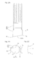
- Fig. 1 shows a mount system of a punch press to which a nibbler assembly according to a first embodiment of the invention is mounted.
- the nibbler assembly includes a punch 1 and a die 11, and a punching operation is carried out by positioning a sheet material W on the die 11 such that the sheet material W extends in a horizontal plane and then lowering the punch 1 against the sheet material W.
- the punch 1 includes a haft 2 and a blade 3 provided at a lower end of the haft 2.
- the blade 3 is oblong, for example rectangular, in a cross sectional shape thereof, and has a bottom surface that is inclined upwardly towards the upstream (the right side of Fig. 2A ) of a feed direction A in which the sheet material W is fed.
- the bottom surface of then blade 3 has a constant height level with respect to a direction perpendicular to the feed direction A (i.e., a direction perpendicular to the surface plane of the paper of Fig. 2A ).
- the bottom surface of the blade 3 has four sides forming respective punch edges 3a, 3b, 3c, 3d which cooperate with the die edges 12aa, 12ab, 12ac, 12ad (which will be described in detail later), respectively, of the die 11 to punch the sheet material W.
- the punch 1 is oriented to perform a nibbling operation.
- the blade 3 has a lateral cross sectional shape in which a dimension in a width direction perpendicular to the feed direction A is gradually decreasing towards the downstream of the feed direction A.
- the blade 3 may have a lateral cross sectional shape that is not of an exact rectangle but of a trapezoid or a trapezium as shown in Fig. 3A .
- the lateral cross sectional shape of the blade 3 may as well be said to be oblong or substantially rectangular, since the change of the dimension in the width direction is quite small.
- the dimension in the width direction of the blade 3 decreases over the entire shape thereof along the feed direction A, as shown in Fig. 3B , only a partial segment or range R of the blade 3 to form the overlapped portion between the successive punched holes may have a shape in which the dimension in the width direction perpendicular to the feed direction A is gradually decreasing towards the downstream of the feed direction A.
- the blade 3 includes an upstream end portion in the feed direction A provided with opposite arcuate corners 4, each having an arcuate shape as viewed in a plan view (e.g., as viewed along a vertical direction that is substantially perpendicular to the feed direction A.).
- the blade 3 includes a downstream end portion in the feed direction A provided with opposite square corners 5, each having a right angle shape as viewed in the plan view.
- the die 11 includes a die body having a shape of substantially circular as viewed in the plan view and a through opening 12 formed in the die body and extending through the die body from a top to a bottom thereof.
- the through opening 12 is of an oblong configuration, such as a rectangular configuration, as viewed in the plan view so that the blade 3 of the punch 1 enters the through opening 12.
- the through opening 12 is in the form of a slit.
- the through opening 12 is a stepped opening that is elongated in the feed direction A and includes an upper opening portion 12a of a configuration having a lateral cross section that substantially matches in shape with the blade 3 of the punch 1.
- the upper opening portion 12a has four sides which form the aforementioned die edges 12aa, 12ab, 12ac, 12ad that engage with the punch edges 3a, 3b, 3c, 3d, respectively, of the punch 1.
- the die 11 has an upper surface formed with a recess 13 extending from an upper peripheral portion of the through opening 12 at an upstream side of the feed direction A towards the upstream of the feed direction A, and the recess 13 is dented downwardly compared with other portions of the upper surface.
- the punch 1 and the die 11 of the nibbler assembly are mounted to the mount system of the punch press for operation.
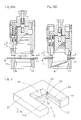
- the punch 1 is secured to a head member 21 via a set bolt 22, and is mounted for up and down movement via a punch holder 23 in a punch mount hole 25 of an upper turret 24 of the punch press.
- the head member 21 includes a T-shaped head that engages with a ram 26 of a punch drive mechanism (not shown) of the punch press, and is driven to move up and down by the mechanism.
- the punch drive mechanism may be a crank mechanism or a hydraulic mechanism.
- the punch holder 23 is movably arranged with respect to the upper turret 24 in an up and down direction and is urged downwardly by a set of holding springs 27A, 27B.
- the punch holder 23 includes a lower end fixedly provided with a stripper plate 28.
- the punch 1 forms an indexable tool that can adjust an angular position thereof.
- the punch mount hole 25 is formed in a rotary member 31 that is rotatable relative to a turret body 24a of the upper turret 24.
- the rotary member 31 has an outer peripheral surface provided with a worm wheel 32 engageable with a worm gear 34 provided in a rotational shaft 33 extending radially of the turret 24 or radially of the punch mount hole 25. Rotation of the rotational shaft 33 by a drive mechanism is transmitted to the rotary member 31 via the worm gear 34 and the worm wheel 32, to index the punch 1 to the desired angular position.
- the die 11 forms an indexable tool that can adjust an angular position thereof.
- a die holder 37 for holding the die 11 is rotatably mounted to a lower turret 36 of the punch press.
- the die holder 37 has an outer peripheral surface provided with a worm wheel 38 engaeable with a worm gear 40 provided in a rotational shaft 39 extending radially of the lower turret 36 or radially of the die 11. Rotation of the rotational shaft 39 by a drive mechanism is transmitted to the die holder 37 via the worm gear 40 and the worm wheel 38, to index the die 11 to the desired angular position.
- Each of the upper and lower turrets 24, 36 is a die support member for supporting various kinds of tools to perform a punching operation at a plurality of circumferential locations thereof, and in the illustrated example, as one of such tools the punch 1 and the die 11 are mounted to the upper and lower turrets 24, 36 for the nibbler assembly, respectively.
- a punch (not shown) and a die (not shown) for use other than in a nibbler assembly may be mounted to the upper and lower turrets 24, 36, respectively, in a configuration indexable to a desired angular position.
- a punch press having such a nibbler assembly may necessarily not be a turret punch press, and the punch and the die may be mounted to a die support member which is not a turret-type.
- an elongated hole 50 such as shown in Fig. 5D is to be formed in the sheet material W.
- successive holes 51 are punched in the sheet material W such that the successive holes 51 at least partially have an overlap with each other along the feed direction A.
- Fig. 6A and Fig. 6B illustrate a first punching stroke.
- the sheet material W is positioned with respect to the punch 1 and the die 11 such that a starting end of the elongated hole 50 to be formed assumes the same position on a plane surface as the punch 1 and the die 11.
- a sheet material W is positioned with respect to the punch 1 and the die 11 such that the first hole to be produced by the punch 1 and the die 11 corresponds to the starting end of the elongated hole 50 to be formed.
- the punch 1 is lowered against the sheet material W as shown in Fig. 6B , to punch a hole 51(1) such as shown in Fig. 5A .
- a punched piece Wa punched out from the sheet material W falls through the through opening 12 of the die 11.
- the die edge 12aa which is the most proximal to the upstream in the feed direction A of the die 11 has a height smaller than those of other die edges 12ab, 12ac, 12ad.
- the part of the sheet material W that is adjacent the end of the punched hole 51 which, in turn, is more proximal to the upstream of the feed direction A becomes a processed portion 52 deformed downwardly by an amount corresponding to the depth of the recess 13 of the die 11 such as shown in Fig. 7 .
- the blade 3 of the punch 1 includes the upstream end portion in the feed direction A provided with the arcuate corners 4, each of the arcuate corners 4 having an arcuate shape as viewed in a plan view, as shown in Fig. 8 , the distance B at the arcuate corner 4 between the punch 1 and the upper end edge of the punched hole 51 is substantially the same as the distance C at other locations, that define straight lines, between the punch 1 and the upper end edge of the punched hole 51. Therefore, a shear droop surface 53 as well as a fracture surface 55 below a sheared surface 54 can be formed at a corner 51a of the punched hole 51, just as at other locations of the punched hole 51, such as shown in Fig. 7 .
- Fig. 9A and Fig. 9B illustrate a second punching stroke.
- the sheet material W is positioned with respect to the punch 1 and the die 11 such that the end edge of the punched hole 51(1) made by the first punching stroke, which edge is adjacent the upstream of the feed direction A, has an overlap with the punch 1 and the die 11 as viewed in a plan view.
- the die 1 is lowered against the sheet material W as shown in Fig. 9B , to punch a hole 51(2) such as shown in Fig. 5B .
- a seam-like portion formed at ends of an overlapped portion between successive holes 51(1), 51 (2) can be minimized such as shown in Fig. 10 by the combination of the following two effects.
- the part of the sheet material W that is adjacent the edge of a punched hole 51(1) by the first punching stroke, which, in turn, is more proximal to the upstream of the feed direction A is rendered to be a processed portion 52 that is deformed downwardly.
- the shear droop surface 53 (such as shown in Fig. 7 ) is formed at each of the corners 51a of the punched hole 51(1), which corners 51a are more proximal to the upstream of the feed direction A.
- the formation of a seam-like segment 56 on the shear droop surface 53 can be minimized. Also, since the fracture surface 55 (such as shown in Fig. 7 ) can be formed in the lower part at the corner 51a of the punched hole 51(1), the formation of protrusions 57 in the lower part of the cut surface can be minimized when the next hole is punched.
- a fracture surface 55 (such as shown in Fig. 7 ) is formed at each corner 51a of the punched hole 51(1), even when the sheared surface 54 is rubbed and stretched downwardly by a side surface of the blade 3 of the punch 1 during the second punching stroke, an amount of protrusion from the bottom surface of the sheet material W is limited.
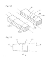
- the blade 3 of the punch 1 has a shape such that the width dimension is gradually decreasing towards the upstream of the feed direction A, in the case of a nibbling operation, a side surface F2 of the blade 3 of the punch 1 is spaced apart from a side wall surface F1 of the previously punched hole 51 by a gap S such as shown in Fig.
- the side surface F2 of the blade 3 does not contact and rub the side wall surface F1 of the previously punched hole 51. Therefore, the formation of the prong 58 (such as shown in Fig. 13 ) protruding from the bottom surface of the sheet material W can be minimized.
- Fig. 12A and Fig. 12B illustrate the finishing punching stroke.
- the orientations of the punch 1 and the die 11 are reversed along the feed direction A.
- the sheet material W is positioned with respect to the punch 1 and the die 11 such that the finishing end of the elongated hole 50 to be formed assumes the same position as the punch 1 and the die 11 as viewed in the plan view.
- the punch 1 is lowered against the sheet material W as shown in Fig. 12B , to punch a hole 51(L) such as shown in Fig. 5D .
- the end of that finishing hole 51(L) that is adjacent the upstream of the feed direction A will have an oblong shape, for example a rectangular shape, as viewed along the vertical direction, which is similar to the shapes of the ends of the holes punched on the downstream of the feed direction A.
- the elongated hole 50 can be formed with a single set of the nibbler assembly.
- a control system can be simplified since the stroke length of punch I is substantially constant in all punching strokes. Also, a smaller overlap margin can be achieved between the successive holes along the feed direction A, compared with a conventional nibbler assembly having a slant cutter blade section mentioned above, thereby resulting in improved process efficiency. Also, as compared with nibbler assemblies described in Japanese Patent Nos. 3401908 and 3960066 , a simplified construction can be realized and therefore can be manufactured with low cost.
Landscapes
- Engineering & Computer Science (AREA)
- Mechanical Engineering (AREA)
- Perforating, Stamping-Out Or Severing By Means Other Than Cutting (AREA)
- Punching Or Piercing (AREA)
Abstract
Description
- The present invention relates to a nibbler assembly for a punch press to perform a nibbling operation to a sheet material, a method of forming an elongated hole in the sheet material with such a nibbler assembly, and a punch for a punch press to perform a nibbling operation to the sheet material.
- In a nibbling operation to a sheet material with a punch press, a conventional process may include the use of a die and a punch to punch a plurality of successive holes that at least partially have an overlap with each other. The die may include a through opening formed therein and having an oblong configuration. Such a conventional process may leave a seam-like portion at one end of the overlap between the successive holes, which may deteriorate an appearance or may give an uncomfortable touch. Such a seam-like portion consists of the following components (see
Fig. 13 ). - Assuming that a punch of a laterally rectangular configuration is used to punch a
hole 51, a roll-over or shear droop may not be formed at the upper end edge 51aa of thecorner 51a of thepunched hole 51, as shown inFig. 14 . This results in the formation of a seam-like segment 56 on a roll-oversurface 53. More specifically, the upper end edge 51aa of thecorner 51a with no roll-over leaves a projection when thenext hole 51 is punched. It has been found that the absence of roll-over at the upper end edge 51aa of thecorner 51a is caused by the greater distance between apunch 1 and thepunched hole 51 at thecorner 51a than the distance C at other locations (B>C), as is illustrated inFig. 15 . This greater distance at thecorner 51 a makes it difficult to impart the punching force of thepunch 1 to a sheet material W. - Also, at the
corner 51a of thepunched hole 51, the punched surface is not made of a fractured surface. Instead, as shown inFig. 14 , a burnished orsheared surface segment 54a continues to the lower end of the punched surface, causing the formation of aprotrusion 57 on the punched surface. Note that the fracturedsurface 55 is depressed with respect to asheared surface 54, as is illustrated byFig. 16 . Therefore, of thesheared surface segment 54a left in the previously punchedhole 51, the part that extending to the lower end remains in the form of a projection protruding from the surrounding fractured surfaces, when thenext hole 51 is punched. - Moreover, since at the
corner 51a of thepunched hole 51 previously punched in the sheet material W, thesheared surface segment 54a (Fig. 14 ) continuing to the lower end of the sheet material W, thesheared surface segment 54a is rubbed and stretched downwardly by a side surface of thepunch 1 when it punches thenext hole 51. This results in the formation of aprong 58 that protrudes from the bottom surface of the sheet material W. Theprong 58 is a burr of larger size. - Conventionally, these seam-like segments are manually treated, for example, with a sander or a file. Manual treatments not only lead to a variation in the finishing quality due to the skill of attendant workers but also involve more process steps, thereby lowering the process efficiency.
- In order to eliminate the formation of such seam-like segments of various kinds or make them as invisible as possible, a punching technique has been proposed which uses a nibbler assembly with a cutter blade section having a bottom surface slant with respect to a horizontal axis. The slant cutter blade section is not configured to punch a complete hole in a sheet material, but is only configured to make small slits that facilitate a complete cutting in the next punching stroke (see, for example, Japanese Patent No.
3401908 3960066 4518539 S61-009895 - The above proposed techniques enable the formation of roll-over or shear droop and fractured surfaces at each corner of a punched hole, just as in other locations of the punched hole. With such techniques, a nibbling operation to form successive holes with a partial overlap with each other allows for aesthetic finishing of the overlapped portion between successive holes, resulting in a smooth and continuous surface textures. However, the kind of punch used in these techniques has a complex shape and is accordingly expensive. Also, since the sheet material is not punched out by the slant cutter blade section, a hole that can be punched per stroke is of a limited length and accordingly, the process efficiency is low. Furthermore, complicated control must be implemented to assure a fine adjustment of the stroke length of the punch.
- An object of the invention is to provide an inexpensive nibbler assembly for a punch press that can perform a nibbling operation with more efficiency and can make a smooth finishing of the overlaps between successive punched holes.
- A nibbler assembly for a punch press is operable to punch in a sheet material successive holes that at least partially have an overlap with each other along a feed direction in which the sheet material is fed from an upstream to a downstream thereof so as to form an elongated hole in the sheet material. The nibbler assembly includes a die that includes a through opening formed therein. The through opening has an oblong configuration as viewed along a vertical direction or in a plan view. The die has an upper surface formed with a recess extending from an upper peripheral portion of the through opening at an upstream side of the feed direction towards the upstream of the feed direction, and the recess is dented downwardly than other portions of the upper surface. The nibbler assembly also includes a punch that includes a blade substantially matching in shape with the through opening and configured to enter the through opening. The blade includes an upstream end portion in the feed direction provided with opposite corners each having an arcuate shape as viewed along the vertical direction.
- With such a nibbler assembly, the sheet material is positioned on the die such that the sheet material extends in a horizontal direction and the punch is lowered against the sheet material to perform a punching operation. In this way, a hole of an oblong shape, such as a rectangular shape, is punched in the sheet material, with the shape matching with the die and the punch as viewed along the vertical direction.
- As discussed above, the die has an upper surface formed with a recess extending from an upper peripheral portion of the through opening at an upstream side of the feed direction towards the upstream of the feed direction, and the recess is dented downwardly compared with other portions of the upper surface. As a result, the part of the sheet material that is adjacent the edge of the punched hole, which, in turn, is more proximal to the upstream of the feed direction, is deformed downwardly by an amount corresponding to the depth of the recess to form a processed portion.
- Also, as discussed above, the punch includes the blade having an upstream end portion in the feed direction provided with opposite corners each having an arcuate shape as viewed along the vertical direction. Therefore, the distance between the punch and the punched hole at the corners of the punched hole is substantially the same as at other locations. As a result, a roll-over or shear droop surface can be formed at the corners of the punched hole.
- The seam-like portion formed on the shear droop surface can be minimized when performing a nibbling operation of punching in the sheet material successive holes that at least partially have an overlap with each other. This advantage is derived by the combination of the following two effects. Firstly, the part of the sheet material that is adjacent the edge of a previously punched hole, which, in turn, is more proximal to the upstream of the feed direction, is rendered to be the processed portion that is deformed downwardly. Secondly, the shear droop surface is formed at the corners of the previously punched hole, which corners are more proximal to the upstream of the feed direction. Also, since a fracture surface is formed at each corner of the previous punched hole, no burnished or sheared surface, when the next hole is punched, remains at the lower part of the sheared surface, thereby not forming the aforementioned type of protrusion on the sheared surface. Furthermore, since such a fracture surface is formed at each corner of the previously punched hole, even when the fracture surface is rubbed and stretched downwardly by a side surface of the punch during punching process, an amount of protrusion from the bottom surface of the sheet material is limited. As a result, a protrusion or prong from the bottom surface of the sheet material can be minimized.
- The recess of the die and the arcuate shape corners of the blade of the punch are formed only on the upstream side of the feed direction. Therefore, by positioning the die and the punch such that the orientations of these are reversed along the feed direction and then carrying out punching by means of them, the edge of the punched hole that is adjacent the upstream of the feed direction is made of an oblong shape, for example a rectangular shape, as viewed along the vertical direction which is similar to the shape of the punched hole on the downstream side of the feed direction. In this way, the elongated hole can be formed with a single set of nibbler assembly.
- In a nibbling operation with this nibbler assembly, a smaller overlap margin can be achieved between the successive holes along the feed direction, compared with a conventional nibbler assembly having the slant cutter blade mentioned above, thereby resulting in improved process efficiency. Also, this nibbler assembly, as compared with those described in Japanese Patent No.
3401908 3960066 - In the present invention, the punch may include a segment corresponding to the overlap between the successive holes and the segment may have a shape such that a width dimension in a direction perpendicular to the feed direction decreases towards the downstream of the feed direction.
- With such a construction, the cut surface of the corner of a previously punched hole will not be rubbed and stretched downwardly by a side surface of the punch. Therefore, the protrusion from the bottom surface of the sheet material can be further minimized.
- A method of forming an elongated hole in a sheet material includes the step of providing a die and a punch, the die including a through opening formed therein, the through opening having an oblong configuration as viewed along a vertical direction, the die having an upper surface formed with a recess extending from an upper peripheral portion of the through opening at an upstream side of the feed direction towards the upstream of the feed direction, the recess being dented downwardly than other portions of the upper surface, the punch including a blade substantially matching in shape with the through opening and configured to enter the through opening, the blade including an upstream end portion in the feed direction provided with opposite corners each having an arcuate shape as viewed along the vertical direction. The method further includes the step of driving the punch to punch in the sheet material successive holes such that the successive holes at least partially have an overlap with each other along the feed direction, thereby to perform a nibbling operation that forms the elongated hole in the sheet material.
- Such a method has the same advantages that can be achieved by a nibbling operation with the aforementioned nibbler assembly.
- Provided is a punch usable in combination with a die to punch in a sheet material successive holes that at least partially have an overlap with each other along a feed direction in which the sheet material is fed from an upstream to a downstream thereof, to perform a nibbling operation that forms an elongated hole in the sheet material, in which the die includes a through opening formed therein and the through opening has an oblong configuration as viewed along a vertical direction. The punch includes a blade substantially matching in shape with the through opening and configured to enter the through opening. The blade includes an upstream end portion in the feed direction provided with opposite corners each having an arcuate shape as viewed along the vertical direction.
- For example, such a punch may be used to carry out a nibbling operation in combination with a die that includes a through opening, with the through opening of an oblong configuration as viewed along the vertical direction. In such case, the same advantages as the nibbling operation with the aforementioned nibbler assembly can be achieved.
- The present invention will be more apparent from the following description of preferred embodiments, as illustrated in the accompanying drawings in which like reference characters refer to the same parts throughout the different views. Note that the embodiments herein and the drawings are merely for exemplary and illustration purposes, and should not be taken as limiting the scope of the invention which is defined by the claims; and
-
Fig. 1 is a longitudinal cross sectional view showing a mount system of a punch press to which a nibbler assembly according to a first embodiment of the present invention is mounted; -
Fig. 2A is a front elevational view showing a punch of the nibbler assembly ofFig. 1 ; -
Fig. 2B is a bottom plan view of a punch of the nibbler assembly ofFig. 2A ; -
Fig. 2C is a fragmentary enlarged view ofFig. 2B ; -
Fig. 3A is a schematic view showing the shape of the bottom surface of a blade of the punch; -
Fig. 3B is a bottom plan view showing the shape of the bottom surface of the blade of the punch, which shape is different from the one illustrated inFig. 3A ; -
Fig. 4A is a top plan view showing a die of the nibbler assembly ofFig. 1 ; -
Fig. 4B is a cutaway front elevational view of the die ofFig. 4A ; -
Figs. 5A to 5D show an example of the process steps in forming an elongated hole in a sheet material with the nibbler assembly; -
Fig. 6A is a longitudinal cross sectional view showing the mount system at a stage before a first punching stroke is applied to the sheet material, in the course of forming the elongated hole in the sheet material; -
Fig. 6B is a longitudinal cross sectional view showing the mount system at a stage after the first punching stroke is applied to the sheet material, in the course of forming the elongated hole in the sheet material; -
Fig. 7 is a perspective view showing a corner of a punched hole with the nibbler assembly; -
Fig. 8 is a top plan view showing a relative positional relationship between the punch and an upper end edge of a hole punched with the nibbler assembly; -
Fig. 9A is a longitudinal cross sectional view showing the mount system at a stage before the second punching stroke is applied to the sheet material, in the course of forming the elongated hole in the sheet material; -
Fig. 9B is a longitudinal cross sectional view showing the mount system at a stage after the second punching stroke is applied to the sheet material, in the course of forming the elongated hole in the sheet material; -
Fig. 10 is a perspective view showing a cut surface of the hole punched with the nibbler assembly; -
Fig. 11 is a top plan view illustrating a relative plan positional relationship between the punch and the hole punched with the nibbler assembly; -
Fig. 12A is a longitudinal cross sectional view showing the mount system at a stage before the finishing punching stroke is applied to a sheet material, in the course of forming the elongated hole in the sheet material; -
Fig. 12B is a longitudinal cross sectional view showing the mount system at a stage after the finishing punching stroke is applied to the sheet material, in the course of forming the elongated hole in the sheet material; -
Fig. 13 is a perspective view showing a cut surface of a hole punched with a conventional nibbler assembly; -
Fig. 14 is a perspective view showing a corner of the hole punched with the conventional nibbler assembly; -
Fig. 15 is a top plan view illustrating a relative positional relationship between a punch of the conventional nibbler assembly and an upper end edge of the hole punched with the conventional nibbler assembly; and -
Fig. 16 is a cross sectional view showing the cut surface of the sheet material punched with the conventional nibbler assembly. - Preferred embodiments of the present invention will be described in connection with the drawings.
-
Fig. 1 shows a mount system of a punch press to which a nibbler assembly according to a first embodiment of the invention is mounted. The nibbler assembly includes apunch 1 and adie 11, and a punching operation is carried out by positioning a sheet material W on the die 11 such that the sheet material W extends in a horizontal plane and then lowering thepunch 1 against the sheet material W. - As shown in
Fig. 2A and Fig. 2B , thepunch 1 includes ahaft 2 and ablade 3 provided at a lower end of thehaft 2. Theblade 3 is oblong, for example rectangular, in a cross sectional shape thereof, and has a bottom surface that is inclined upwardly towards the upstream (the right side ofFig. 2A ) of a feed direction A in which the sheet material W is fed. The bottom surface of thenblade 3 has a constant height level with respect to a direction perpendicular to the feed direction A (i.e., a direction perpendicular to the surface plane of the paper ofFig. 2A ). The bottom surface of theblade 3 has four sides formingrespective punch edges Fig. 2A and Fig. 2B , thepunch 1 is oriented to perform a nibbling operation. - In detail, the
blade 3 has a lateral cross sectional shape in which a dimension in a width direction perpendicular to the feed direction A is gradually decreasing towards the downstream of the feed direction A. In other words, theblade 3 may have a lateral cross sectional shape that is not of an exact rectangle but of a trapezoid or a trapezium as shown inFig. 3A . Nevertheless, the lateral cross sectional shape of theblade 3 may as well be said to be oblong or substantially rectangular, since the change of the dimension in the width direction is quite small. Although, inFig. 3A the dimension in the width direction of theblade 3 decreases over the entire shape thereof along the feed direction A, as shown inFig. 3B , only a partial segment or range R of theblade 3 to form the overlapped portion between the successive punched holes may have a shape in which the dimension in the width direction perpendicular to the feed direction A is gradually decreasing towards the downstream of the feed direction A. - As shown in
Fig. 2C illustrating a fragmentary enlarged view of the ellipse E ofFig. 2B , theblade 3 includes an upstream end portion in the feed direction A provided with oppositearcuate corners 4, each having an arcuate shape as viewed in a plan view (e.g., as viewed along a vertical direction that is substantially perpendicular to the feed direction A.). Theblade 3 includes a downstream end portion in the feed direction A provided with oppositesquare corners 5, each having a right angle shape as viewed in the plan view. - As shown in
Fig. 4A and Fig. 4B , thedie 11 includes a die body having a shape of substantially circular as viewed in the plan view and a throughopening 12 formed in the die body and extending through the die body from a top to a bottom thereof. The throughopening 12 is of an oblong configuration, such as a rectangular configuration, as viewed in the plan view so that theblade 3 of thepunch 1 enters the throughopening 12. In the illustrated example, the throughopening 12 is in the form of a slit. As shown inFig. 4B , the throughopening 12 is a stepped opening that is elongated in the feed direction A and includes anupper opening portion 12a of a configuration having a lateral cross section that substantially matches in shape with theblade 3 of thepunch 1. Theupper opening portion 12a has four sides which form the aforementioned die edges 12aa, 12ab, 12ac, 12ad that engage with the punch edges 3a, 3b, 3c, 3d, respectively, of thepunch 1. Thedie 11 has an upper surface formed with arecess 13 extending from an upper peripheral portion of the throughopening 12 at an upstream side of the feed direction A towards the upstream of the feed direction A, and therecess 13 is dented downwardly compared with other portions of the upper surface. - As shown in
Fig. 1 , thepunch 1 and the die 11 of the nibbler assembly are mounted to the mount system of the punch press for operation. Thepunch 1 is secured to ahead member 21 via aset bolt 22, and is mounted for up and down movement via apunch holder 23 in apunch mount hole 25 of anupper turret 24 of the punch press. Thehead member 21 includes a T-shaped head that engages with aram 26 of a punch drive mechanism (not shown) of the punch press, and is driven to move up and down by the mechanism. The punch drive mechanism may be a crank mechanism or a hydraulic mechanism. Thepunch holder 23 is movably arranged with respect to theupper turret 24 in an up and down direction and is urged downwardly by a set of holdingsprings punch holder 23 includes a lower end fixedly provided with astripper plate 28. - The
punch 1 forms an indexable tool that can adjust an angular position thereof. In particular, thepunch mount hole 25 is formed in arotary member 31 that is rotatable relative to aturret body 24a of theupper turret 24. Therotary member 31 has an outer peripheral surface provided with aworm wheel 32 engageable with aworm gear 34 provided in arotational shaft 33 extending radially of theturret 24 or radially of thepunch mount hole 25. Rotation of therotational shaft 33 by a drive mechanism is transmitted to therotary member 31 via theworm gear 34 and theworm wheel 32, to index thepunch 1 to the desired angular position. - Likewise, the die 11 forms an indexable tool that can adjust an angular position thereof. In particular, a
die holder 37 for holding thedie 11 is rotatably mounted to alower turret 36 of the punch press. Thedie holder 37 has an outer peripheral surface provided with aworm wheel 38 engaeable with aworm gear 40 provided in arotational shaft 39 extending radially of thelower turret 36 or radially of thedie 11. Rotation of therotational shaft 39 by a drive mechanism is transmitted to thedie holder 37 via theworm gear 40 and theworm wheel 38, to index the die 11 to the desired angular position. - Each of the upper and
lower turrets punch 1 and the die 11 are mounted to the upper andlower turrets lower turrets - The punching operation with the nibbler assembly that includes the
punch 1 and the die 11 will be described below, in which anelongated hole 50 such as shown inFig. 5D is to be formed in the sheet material W. In general,successive holes 51 are punched in the sheet material W such that thesuccessive holes 51 at least partially have an overlap with each other along the feed direction A. -
Fig. 6A and Fig. 6B illustrate a first punching stroke. As shown inFig. 6A , the sheet material W is positioned with respect to thepunch 1 and the die 11 such that a starting end of theelongated hole 50 to be formed assumes the same position on a plane surface as thepunch 1 and thedie 11. In particular, a sheet material W is positioned with respect to thepunch 1 and the die 11 such that the first hole to be produced by thepunch 1 and thedie 11 corresponds to the starting end of theelongated hole 50 to be formed. With the sheet material W being kept in the position, thepunch 1 is lowered against the sheet material W as shown inFig. 6B , to punch a hole 51(1) such as shown inFig. 5A . A punched piece Wa punched out from the sheet material W falls through the through opening 12 of thedie 11. - Since the
die 11 includes the upper surface provided with therecess 13, the die edge 12aa which is the most proximal to the upstream in the feed direction A of the die 11 has a height smaller than those of other die edges 12ab, 12ac, 12ad. As a result, when the sheet material W is punched through with thepunch 1, the part of the sheet material W that is adjacent the end of the punchedhole 51 which, in turn, is more proximal to the upstream of the feed direction A becomes a processedportion 52 deformed downwardly by an amount corresponding to the depth of therecess 13 of the die 11 such as shown inFig. 7 . - Since the
blade 3 of thepunch 1 includes the upstream end portion in the feed direction A provided with thearcuate corners 4, each of thearcuate corners 4 having an arcuate shape as viewed in a plan view, as shown inFig. 8 , the distance B at thearcuate corner 4 between thepunch 1 and the upper end edge of the punchedhole 51 is substantially the same as the distance C at other locations, that define straight lines, between thepunch 1 and the upper end edge of the punchedhole 51. Therefore, ashear droop surface 53 as well as afracture surface 55 below a shearedsurface 54 can be formed at acorner 51a of the punchedhole 51, just as at other locations of the punchedhole 51, such as shown inFig. 7 . -
Fig. 9A and Fig. 9B illustrate a second punching stroke. As shown inFig. 9A , the sheet material W is positioned with respect to thepunch 1 and the die 11 such that the end edge of the punched hole 51(1) made by the first punching stroke, which edge is adjacent the upstream of the feed direction A, has an overlap with thepunch 1 and the die 11 as viewed in a plan view. With the sheet material W being kept in the position, thedie 1 is lowered against the sheet material W as shown inFig. 9B , to punch a hole 51(2) such as shown inFig. 5B . - In this way, a seam-like portion formed at ends of an overlapped portion between successive holes 51(1), 51 (2) can be minimized such as shown in
Fig. 10 by the combination of the following two effects. Firstly, the part of the sheet material W that is adjacent the edge of a punched hole 51(1) by the first punching stroke, which, in turn, is more proximal to the upstream of the feed direction A is rendered to be a processedportion 52 that is deformed downwardly. Secondly, the shear droop surface 53 (such as shown inFig. 7 ) is formed at each of thecorners 51a of the punched hole 51(1), whichcorners 51a are more proximal to the upstream of the feed direction A. In particular, the formation of a seam-like segment 56 on theshear droop surface 53 can be minimized. Also, since the fracture surface 55 (such as shown inFig. 7 ) can be formed in the lower part at thecorner 51a of the punched hole 51(1), the formation ofprotrusions 57 in the lower part of the cut surface can be minimized when the next hole is punched. - Furthermore, since such a fracture surface 55 (such as shown in
Fig. 7 ) is formed at eachcorner 51a of the punched hole 51(1), even when the shearedsurface 54 is rubbed and stretched downwardly by a side surface of theblade 3 of thepunch 1 during the second punching stroke, an amount of protrusion from the bottom surface of the sheet material W is limited. In particular, since theblade 3 of thepunch 1 has a shape such that the width dimension is gradually decreasing towards the upstream of the feed direction A, in the case of a nibbling operation, a side surface F2 of theblade 3 of thepunch 1 is spaced apart from a side wall surface F1 of the previously punchedhole 51 by a gap S such as shown inFig. 11 , and accordingly, the side surface F2 of theblade 3 does not contact and rub the side wall surface F1 of the previously punchedhole 51. Therefore, the formation of the prong 58 (such as shown inFig. 13 ) protruding from the bottom surface of the sheet material W can be minimized. - The aforementioned procedures of the nibbling operation to the sheet material W, in which the
successive holes 51 at least partially have an overlap with each other, is continued until at a stage (Fig. 5C ) before the formation of the finishing end of theelongated hole 50 to be formed in the sheet material W. At this stage, the finishing punching stroke is applied to the sheet material W. -
Fig. 12A and Fig. 12B illustrate the finishing punching stroke. As shown inFig. 12A , the orientations of thepunch 1 and the die 11 are reversed along the feed direction A. The sheet material W is positioned with respect to thepunch 1 and the die 11 such that the finishing end of theelongated hole 50 to be formed assumes the same position as thepunch 1 and the die 11 as viewed in the plan view. With the sheet material W being kept in the position, thepunch 1 is lowered against the sheet material W as shown inFig. 12B , to punch a hole 51(L) such as shown inFig. 5D . Therefore, by positioning thepunch 1 and the die 11 such that the orientations of them are reversed along the feed direction A and then punching the finishing hole 51 (L) in the sheet material W, the end of that finishing hole 51(L) that is adjacent the upstream of the feed direction A will have an oblong shape, for example a rectangular shape, as viewed along the vertical direction, which is similar to the shapes of the ends of the holes punched on the downstream of the feed direction A. In this way, theelongated hole 50 can be formed with a single set of the nibbler assembly. - A control system can be simplified since the stroke length of punch I is substantially constant in all punching strokes. Also, a smaller overlap margin can be achieved between the successive holes along the feed direction A, compared with a conventional nibbler assembly having a slant cutter blade section mentioned above, thereby resulting in improved process efficiency. Also, as compared with nibbler assemblies described in Japanese Patent Nos.
3401908 3960066 - Although the present invention has been fully described in connection with the preferred embodiments thereof with reference to the accompanying drawings which are used only for the purpose of illustration, those skilled in the art will readily conceive numerous changes and modifications within the framework of obviousness upon the reading of the specification herein presented of the present invention. Accordingly, such changes and modifications are, unless they depart from the scope of the present invention as delivered from the claims annexed hereto, to be construed as included therein.
-
- 1:
- PUNCH
- 3:
- BLADE
- 4:
- CORNER
- 11:
- DIE
- 12:
- THROUGH OPENING
- 13:
- RECESS
- 51:
- PUNCHED HOLE
- A:
- FEED DIRECTION
- W:
- SHEET MATERIAL
Claims (5)
- A nibbler assembly (1, 11) for a punch press, the nibbler assembly (1, 11) being operable to punch in a sheet material (W) successive holes (51(1), 51(2), ··· 51(L)) that at least partially have an overlap with each other along a feed direction (A) in which the sheet material (W) is fed from an upstream to a downstream in the feed direction (A) so as to form an elongated hole (51) in the sheet material (W), the nibbler assembly (1, 11) characterized by:a die (11) including a through opening (12) formed therein, the through opening (12) having an oblong configuration as viewed along a vertical direction, the die (11) having an upper surface formed with a recess (13) extending from an upper peripheral portion of the through opening (12) at an upstream side of the feed direction (A) towards the upstream of the feed direction (A), the recess (13) being dented downwardly compared with other portions of the upper surface; anda punch (1) including a blade (3) substantially matching in shape with the through opening (12) and configured to enter the through opening (12), the blade (3) including an upstream end portion (3a) in the feed direction (A) provided with opposite corners (4) each having an arcuate shape as viewed along the vertical direction.
- The nibbler assembly (1, 11) as claimed in claim 1, characterized in that the punch (1) includes a segment to form the overlapped portion between the successive punched holes (51(1), 51(2), ··· 51(L)) and at least the segment has a shape such that a width dimension in a direction perpendicular to the feed direction (A) decreases towards the downstream of the feed direction (A).
- A method of forming an elongated hole (51) in a sheet material (W), characterized by the steps of:providing a die (11) and a punch (1),the die (11) including a through opening (12) formed therein, the through opening (12) having an oblong configuration as viewed along a vertical direction, the die (11) having an upper surface formed with a recess (13) extending from an upper peripheral portion of the through opening at an upstream side of the feed direction (A) towards the upstream of the feed direction (A), the recess (13) being dented downwardly compared with other portions of the upper surface, andthe punch (1) including a blade (3) substantially matching in shape with the through opening (12) and configured to enter the through opening (12), the blade (3) including an upstream end portion (3a) in the feed direction (A) provided with opposite corners (4) each having an arcuate shape as viewed along the vertical direction; anddriving the punch (1) to punch in the sheet material (W) successive holes (51(1), 51(2), ··· 51(L)) such that the successive holes (51(1), 51(2), ··· 51(L)) at least partially have an overlap with each other along the feed direction (A), thereby to perform a nibbling operation that forms the elongated hole (51) in the sheet material (W).
- A punch (1) usable in combination with a die (11) to punch in a sheet material (W) successive holes (51(1), 51(2), ··· 51(L)) that at least partially have an overlap with each other along a feed direction (A) in which the sheet material (W) is fed from an upstream to a downstream thereof, to perform a nibbling operation that forms an elongated hole (51) in the sheet material (W), the die (11) including a through opening (12) formed therein, the through opening (12) having an oblong configuration as viewed along a vertical direction, the punch (1) being characterized by:a blade (3) substantially matching in shape with the through opening (12) and configured to enter the through opening (12), the blade (3) including an upstream end portion (3a) in the feed direction (A) provided with opposite corners (4) each having an arcuate shape as viewed along the vertical direction.
- The punch (1) as claimed in claim 4, further characterized by a segment to form the overlapped portion between the successive punched holes (51(1),51(2), ··· 51(L)), at least the segment having a shape such that a width dimension in a direction perpendicular to the feed direction (A) decreases towards the downstream of the feed direction (A).
Applications Claiming Priority (1)
| Application Number | Priority Date | Filing Date | Title |
|---|---|---|---|
| JP2011142536 | 2011-06-28 |
Publications (2)
| Publication Number | Publication Date |
|---|---|
| EP2540428A1 true EP2540428A1 (en) | 2013-01-02 |
| EP2540428B1 EP2540428B1 (en) | 2017-05-10 |
Family
ID=46245944
Family Applications (1)
| Application Number | Title | Priority Date | Filing Date |
|---|---|---|---|
| EP12171705.2A Active EP2540428B1 (en) | 2011-06-28 | 2012-06-12 | Nibbler assembly for punch press and method of forming elongated hole in sheet material |
Country Status (3)
| Country | Link |
|---|---|
| US (1) | US8863626B2 (en) |
| EP (1) | EP2540428B1 (en) |
| JP (1) | JP5982970B2 (en) |
Cited By (3)
| Publication number | Priority date | Publication date | Assignee | Title |
|---|---|---|---|---|
| CN103273537A (en) * | 2013-06-07 | 2013-09-04 | 南通超达机械科技有限公司 | Punching die structure for avoiding product grinning |
| ES2510015A1 (en) * | 2013-04-17 | 2014-10-20 | Geka Automation S.L. | Method and unit for notching metal parts, particularly sheets and profiles (Machine-translation by Google Translate, not legally binding) |
| US20140326034A1 (en) * | 2011-12-22 | 2014-11-06 | Pass Stanztechnik Ag | Die For A Punching Device |
Families Citing this family (5)
| Publication number | Priority date | Publication date | Assignee | Title |
|---|---|---|---|---|
| CN106272704B (en) * | 2016-08-12 | 2017-12-15 | 中山鑫辉精密技术股份有限公司 | Lateral cutting mechanism of sheath mold |
| DE102016118175B4 (en) * | 2016-09-26 | 2018-08-23 | Trumpf Werkzeugmaschinen Gmbh & Co. Kg | Machine tool and method for processing plate-shaped workpieces |
| CN109843465B (en) * | 2016-09-26 | 2020-12-18 | 通快机床两合公司 | Method, machine and grooving tool for multi-stroke progressive grooving of plate workpieces |
| US10399241B2 (en) * | 2017-02-14 | 2019-09-03 | Jerry L. Runstrom | Corner-rounding compression cutter for roofing material |
| JP7381431B2 (en) * | 2020-10-23 | 2023-11-15 | アイダエンジニアリング株式会社 | scrap cutter |
Citations (6)
| Publication number | Priority date | Publication date | Assignee | Title |
|---|---|---|---|---|
| JPS619895B2 (en) | 1980-05-26 | 1986-03-26 | Amada Co Ltd | |
| JPH07265967A (en) * | 1994-03-31 | 1995-10-17 | Amada Co Ltd | Follow cutting method with press, device therefor and die |
| JP3401908B2 (en) | 1994-03-31 | 2003-04-28 | 村田機械株式会社 | Punching punching die and punching cutting method |
| JP3960066B2 (en) | 2002-02-08 | 2007-08-15 | 村田機械株式会社 | Cut-off die for punch press and cutting method |
| JP2009113051A (en) * | 2007-11-02 | 2009-05-28 | Honda Motor Co Ltd | Punch punch |
| JP4518539B2 (en) | 2004-02-27 | 2010-08-04 | 株式会社アマダ | Workpiece machining method |
Family Cites Families (7)
| Publication number | Priority date | Publication date | Assignee | Title |
|---|---|---|---|---|
| JPS5919038A (en) * | 1982-07-22 | 1984-01-31 | Amada Co Ltd | Outrun working and die in punch press |
| US4674373A (en) * | 1984-10-16 | 1987-06-23 | Trumpf Gmbh & Co. | Method and apparatus for nibbling cutouts by rotation of tooling with cutting surfaces of different contours and tooling therefor |
| US4981058A (en) * | 1988-09-14 | 1991-01-01 | Lear Siegler, Inc. | Punch and die set and method adapted to effect parting between adjacent sections of a workpiece |
| JPH055226U (en) * | 1991-07-03 | 1993-01-26 | 株式会社テツク・インターナシヨナル | Mold for continuous cutting of plate materials |
| JPH0523998A (en) * | 1991-07-15 | 1993-02-02 | Aiseru Kk | Card punching device |
| DE60102958T2 (en) * | 2000-02-21 | 2005-04-07 | Honda Giken Kogyo K.K. | Method and device for punching parts of a belt for continuously variable transmission |
| EP1317974B1 (en) * | 2001-12-06 | 2003-07-23 | Trumpf Werkzeugmaschinen GmbH + Co. KG | Method and machine for multiple travel slitting of plate-shaped workpieces, in particular of metal sheets |
-
2012
- 2012-04-10 JP JP2012088904A patent/JP5982970B2/en active Active
- 2012-06-12 EP EP12171705.2A patent/EP2540428B1/en active Active
- 2012-06-13 US US13/495,562 patent/US8863626B2/en active Active
Patent Citations (6)
| Publication number | Priority date | Publication date | Assignee | Title |
|---|---|---|---|---|
| JPS619895B2 (en) | 1980-05-26 | 1986-03-26 | Amada Co Ltd | |
| JPH07265967A (en) * | 1994-03-31 | 1995-10-17 | Amada Co Ltd | Follow cutting method with press, device therefor and die |
| JP3401908B2 (en) | 1994-03-31 | 2003-04-28 | 村田機械株式会社 | Punching punching die and punching cutting method |
| JP3960066B2 (en) | 2002-02-08 | 2007-08-15 | 村田機械株式会社 | Cut-off die for punch press and cutting method |
| JP4518539B2 (en) | 2004-02-27 | 2010-08-04 | 株式会社アマダ | Workpiece machining method |
| JP2009113051A (en) * | 2007-11-02 | 2009-05-28 | Honda Motor Co Ltd | Punch punch |
Cited By (5)
| Publication number | Priority date | Publication date | Assignee | Title |
|---|---|---|---|---|
| US20140326034A1 (en) * | 2011-12-22 | 2014-11-06 | Pass Stanztechnik Ag | Die For A Punching Device |
| US9839952B2 (en) * | 2011-12-22 | 2017-12-12 | Pass Stanztechnik Ag | Die for a punching device |
| ES2510015A1 (en) * | 2013-04-17 | 2014-10-20 | Geka Automation S.L. | Method and unit for notching metal parts, particularly sheets and profiles (Machine-translation by Google Translate, not legally binding) |
| CN103273537A (en) * | 2013-06-07 | 2013-09-04 | 南通超达机械科技有限公司 | Punching die structure for avoiding product grinning |
| CN103273537B (en) * | 2013-06-07 | 2015-07-29 | 南通超达机械科技有限公司 | The die cutting die structure avoiding product to show money or valuables one carries unintentionally |
Also Published As
| Publication number | Publication date |
|---|---|
| JP2013031875A (en) | 2013-02-14 |
| US8863626B2 (en) | 2014-10-21 |
| EP2540428B1 (en) | 2017-05-10 |
| JP5982970B2 (en) | 2016-08-31 |
| US20130000456A1 (en) | 2013-01-03 |
Similar Documents
| Publication | Publication Date | Title |
|---|---|---|
| EP2540428B1 (en) | Nibbler assembly for punch press and method of forming elongated hole in sheet material | |
| US9381559B2 (en) | Punch of punching press, nibbler assembly, and method of forming elongated hole in sheet material | |
| KR101945285B1 (en) | Method for milling an opening in a workpiece and workpiece comprising an opening | |
| CN108213142B (en) | Blanking and trimming dies including integrated power grinding tool | |
| JP2012000631A (en) | Ripping cutting punch mold of punch press, corner cutting punch mold and method of forming plate material opening | |
| US20090010723A1 (en) | Method and Tool for the Precision Cutting of Workpieces with Small Corner Radii and Greatly Reduced Draw-In in a One-Stage Arrangement | |
| US6868763B2 (en) | Method and machine for the continuous multi-stroke slotting of plate-shaped workpieces | |
| JP5801825B2 (en) | Method and apparatus for drawing and trimming blanks | |
| US11471924B2 (en) | Tools, machines, and methods for processing planar workpieces | |
| JPH11197968A (en) | Composite working machine and plate working method using the composite working machine | |
| US20120312064A1 (en) | Punching Sheet Metal | |
| JP6019821B2 (en) | Die for overtaking | |
| JPH057944A (en) | Drawing method | |
| CN112296445A (en) | Method for cutting groove-shaped recesses into workpieces | |
| CN213765950U (en) | Cutting and bending system for forming a plurality of teeth of a cutting blade or guard | |
| EP2957364B1 (en) | Shear beveling with serrations | |
| JPH0569055A (en) | Cutting device for reducing burrs of tabular work | |
| JP2009022976A (en) | Nibbling method for punch press, and punch press | |
| JP5224892B2 (en) | Sheet-shaped workpiece cutting method and apparatus | |
| CN114473004A (en) | Waste material cutting machine | |
| JP6274544B1 (en) | Cutting tool | |
| CN216881996U (en) | Scrap steel shearing equipment | |
| JPS63130227A (en) | Ripping method for press and die for ripping used in its method | |
| JP2007105791A (en) | Trimming die | |
| RU2572008C2 (en) | Low-waste cutting of trapezoidal blanks from sheet reel, tape or strip (versions) |
Legal Events
| Date | Code | Title | Description |
|---|---|---|---|
| PUAI | Public reference made under article 153(3) epc to a published international application that has entered the european phase |
Free format text: ORIGINAL CODE: 0009012 |
|
| AK | Designated contracting states |
Kind code of ref document: A1 Designated state(s): AL AT BE BG CH CY CZ DE DK EE ES FI FR GB GR HR HU IE IS IT LI LT LU LV MC MK MT NL NO PL PT RO RS SE SI SK SM TR |
|
| AX | Request for extension of the european patent |
Extension state: BA ME |
|
| 17P | Request for examination filed |
Effective date: 20121220 |
|
| GRAP | Despatch of communication of intention to grant a patent |
Free format text: ORIGINAL CODE: EPIDOSNIGR1 |
|
| INTG | Intention to grant announced |
Effective date: 20161202 |
|
| GRAJ | Information related to disapproval of communication of intention to grant by the applicant or resumption of examination proceedings by the epo deleted |
Free format text: ORIGINAL CODE: EPIDOSDIGR1 |
|
| GRAP | Despatch of communication of intention to grant a patent |
Free format text: ORIGINAL CODE: EPIDOSNIGR1 |
|
| GRAS | Grant fee paid |
Free format text: ORIGINAL CODE: EPIDOSNIGR3 |
|
| GRAA | (expected) grant |
Free format text: ORIGINAL CODE: 0009210 |
|
| INTC | Intention to grant announced (deleted) | ||
| INTG | Intention to grant announced |
Effective date: 20170329 |
|
| AK | Designated contracting states |
Kind code of ref document: B1 Designated state(s): AL AT BE BG CH CY CZ DE DK EE ES FI FR GB GR HR HU IE IS IT LI LT LU LV MC MK MT NL NO PL PT RO RS SE SI SK SM TR |
|
| REG | Reference to a national code |
Ref country code: GB Ref legal event code: FG4D |
|
| REG | Reference to a national code |
Ref country code: AT Ref legal event code: REF Ref document number: 891768 Country of ref document: AT Kind code of ref document: T Effective date: 20170515 Ref country code: CH Ref legal event code: EP |
|
| REG | Reference to a national code |
Ref country code: IE Ref legal event code: FG4D |
|
| REG | Reference to a national code |
Ref country code: DE Ref legal event code: R096 Ref document number: 602012032163 Country of ref document: DE |
|
| REG | Reference to a national code |
Ref country code: NL Ref legal event code: MP Effective date: 20170510 |
|
| REG | Reference to a national code |
Ref country code: LT Ref legal event code: MG4D |
|
| REG | Reference to a national code |
Ref country code: AT Ref legal event code: MK05 Ref document number: 891768 Country of ref document: AT Kind code of ref document: T Effective date: 20170510 |
|
| PG25 | Lapsed in a contracting state [announced via postgrant information from national office to epo] |
Ref country code: FI Free format text: LAPSE BECAUSE OF FAILURE TO SUBMIT A TRANSLATION OF THE DESCRIPTION OR TO PAY THE FEE WITHIN THE PRESCRIBED TIME-LIMIT Effective date: 20170510 Ref country code: LT Free format text: LAPSE BECAUSE OF FAILURE TO SUBMIT A TRANSLATION OF THE DESCRIPTION OR TO PAY THE FEE WITHIN THE PRESCRIBED TIME-LIMIT Effective date: 20170510 Ref country code: GR Free format text: LAPSE BECAUSE OF FAILURE TO SUBMIT A TRANSLATION OF THE DESCRIPTION OR TO PAY THE FEE WITHIN THE PRESCRIBED TIME-LIMIT Effective date: 20170811 Ref country code: AT Free format text: LAPSE BECAUSE OF FAILURE TO SUBMIT A TRANSLATION OF THE DESCRIPTION OR TO PAY THE FEE WITHIN THE PRESCRIBED TIME-LIMIT Effective date: 20170510 Ref country code: NO Free format text: LAPSE BECAUSE OF FAILURE TO SUBMIT A TRANSLATION OF THE DESCRIPTION OR TO PAY THE FEE WITHIN THE PRESCRIBED TIME-LIMIT Effective date: 20170810 Ref country code: HR Free format text: LAPSE BECAUSE OF FAILURE TO SUBMIT A TRANSLATION OF THE DESCRIPTION OR TO PAY THE FEE WITHIN THE PRESCRIBED TIME-LIMIT Effective date: 20170510 Ref country code: ES Free format text: LAPSE BECAUSE OF FAILURE TO SUBMIT A TRANSLATION OF THE DESCRIPTION OR TO PAY THE FEE WITHIN THE PRESCRIBED TIME-LIMIT Effective date: 20170510 |
|
| PG25 | Lapsed in a contracting state [announced via postgrant information from national office to epo] |
Ref country code: NL Free format text: LAPSE BECAUSE OF FAILURE TO SUBMIT A TRANSLATION OF THE DESCRIPTION OR TO PAY THE FEE WITHIN THE PRESCRIBED TIME-LIMIT Effective date: 20170510 Ref country code: RS Free format text: LAPSE BECAUSE OF FAILURE TO SUBMIT A TRANSLATION OF THE DESCRIPTION OR TO PAY THE FEE WITHIN THE PRESCRIBED TIME-LIMIT Effective date: 20170510 Ref country code: BG Free format text: LAPSE BECAUSE OF FAILURE TO SUBMIT A TRANSLATION OF THE DESCRIPTION OR TO PAY THE FEE WITHIN THE PRESCRIBED TIME-LIMIT Effective date: 20170810 Ref country code: LV Free format text: LAPSE BECAUSE OF FAILURE TO SUBMIT A TRANSLATION OF THE DESCRIPTION OR TO PAY THE FEE WITHIN THE PRESCRIBED TIME-LIMIT Effective date: 20170510 Ref country code: IS Free format text: LAPSE BECAUSE OF FAILURE TO SUBMIT A TRANSLATION OF THE DESCRIPTION OR TO PAY THE FEE WITHIN THE PRESCRIBED TIME-LIMIT Effective date: 20170910 Ref country code: PL Free format text: LAPSE BECAUSE OF FAILURE TO SUBMIT A TRANSLATION OF THE DESCRIPTION OR TO PAY THE FEE WITHIN THE PRESCRIBED TIME-LIMIT Effective date: 20170510 Ref country code: SE Free format text: LAPSE BECAUSE OF FAILURE TO SUBMIT A TRANSLATION OF THE DESCRIPTION OR TO PAY THE FEE WITHIN THE PRESCRIBED TIME-LIMIT Effective date: 20170510 |
|
| PG25 | Lapsed in a contracting state [announced via postgrant information from national office to epo] |
Ref country code: SK Free format text: LAPSE BECAUSE OF FAILURE TO SUBMIT A TRANSLATION OF THE DESCRIPTION OR TO PAY THE FEE WITHIN THE PRESCRIBED TIME-LIMIT Effective date: 20170510 Ref country code: CZ Free format text: LAPSE BECAUSE OF FAILURE TO SUBMIT A TRANSLATION OF THE DESCRIPTION OR TO PAY THE FEE WITHIN THE PRESCRIBED TIME-LIMIT Effective date: 20170510 Ref country code: RO Free format text: LAPSE BECAUSE OF FAILURE TO SUBMIT A TRANSLATION OF THE DESCRIPTION OR TO PAY THE FEE WITHIN THE PRESCRIBED TIME-LIMIT Effective date: 20170510 Ref country code: DK Free format text: LAPSE BECAUSE OF FAILURE TO SUBMIT A TRANSLATION OF THE DESCRIPTION OR TO PAY THE FEE WITHIN THE PRESCRIBED TIME-LIMIT Effective date: 20170510 Ref country code: EE Free format text: LAPSE BECAUSE OF FAILURE TO SUBMIT A TRANSLATION OF THE DESCRIPTION OR TO PAY THE FEE WITHIN THE PRESCRIBED TIME-LIMIT Effective date: 20170510 |
|
| REG | Reference to a national code |
Ref country code: CH Ref legal event code: PL |
|
| REG | Reference to a national code |
Ref country code: DE Ref legal event code: R097 Ref document number: 602012032163 Country of ref document: DE |
|
| PG25 | Lapsed in a contracting state [announced via postgrant information from national office to epo] |
Ref country code: SM Free format text: LAPSE BECAUSE OF FAILURE TO SUBMIT A TRANSLATION OF THE DESCRIPTION OR TO PAY THE FEE WITHIN THE PRESCRIBED TIME-LIMIT Effective date: 20170510 |
|
| PLBE | No opposition filed within time limit |
Free format text: ORIGINAL CODE: 0009261 |
|
| STAA | Information on the status of an ep patent application or granted ep patent |
Free format text: STATUS: NO OPPOSITION FILED WITHIN TIME LIMIT |
|
| REG | Reference to a national code |
Ref country code: IE Ref legal event code: MM4A |
|
| REG | Reference to a national code |
Ref country code: FR Ref legal event code: ST Effective date: 20180228 |
|
| 26N | No opposition filed |
Effective date: 20180213 |
|
| GBPC | Gb: european patent ceased through non-payment of renewal fee |
Effective date: 20170810 |
|
| PG25 | Lapsed in a contracting state [announced via postgrant information from national office to epo] |
Ref country code: LU Free format text: LAPSE BECAUSE OF NON-PAYMENT OF DUE FEES Effective date: 20170612 Ref country code: LI Free format text: LAPSE BECAUSE OF NON-PAYMENT OF DUE FEES Effective date: 20170630 Ref country code: IE Free format text: LAPSE BECAUSE OF NON-PAYMENT OF DUE FEES Effective date: 20170612 Ref country code: CH Free format text: LAPSE BECAUSE OF NON-PAYMENT OF DUE FEES Effective date: 20170630 |
|
| PG25 | Lapsed in a contracting state [announced via postgrant information from national office to epo] |
Ref country code: FR Free format text: LAPSE BECAUSE OF NON-PAYMENT OF DUE FEES Effective date: 20170710 Ref country code: SI Free format text: LAPSE BECAUSE OF FAILURE TO SUBMIT A TRANSLATION OF THE DESCRIPTION OR TO PAY THE FEE WITHIN THE PRESCRIBED TIME-LIMIT Effective date: 20170510 |
|
| REG | Reference to a national code |
Ref country code: BE Ref legal event code: MM Effective date: 20170630 |
|
| PG25 | Lapsed in a contracting state [announced via postgrant information from national office to epo] |
Ref country code: GB Free format text: LAPSE BECAUSE OF NON-PAYMENT OF DUE FEES Effective date: 20170810 |
|
| PG25 | Lapsed in a contracting state [announced via postgrant information from national office to epo] |
Ref country code: BE Free format text: LAPSE BECAUSE OF NON-PAYMENT OF DUE FEES Effective date: 20170630 |
|
| PG25 | Lapsed in a contracting state [announced via postgrant information from national office to epo] |
Ref country code: MT Free format text: LAPSE BECAUSE OF NON-PAYMENT OF DUE FEES Effective date: 20170612 |
|
| PG25 | Lapsed in a contracting state [announced via postgrant information from national office to epo] |
Ref country code: MC Free format text: LAPSE BECAUSE OF FAILURE TO SUBMIT A TRANSLATION OF THE DESCRIPTION OR TO PAY THE FEE WITHIN THE PRESCRIBED TIME-LIMIT Effective date: 20170510 Ref country code: HU Free format text: LAPSE BECAUSE OF FAILURE TO SUBMIT A TRANSLATION OF THE DESCRIPTION OR TO PAY THE FEE WITHIN THE PRESCRIBED TIME-LIMIT; INVALID AB INITIO Effective date: 20120612 |
|
| PG25 | Lapsed in a contracting state [announced via postgrant information from national office to epo] |
Ref country code: CY Free format text: LAPSE BECAUSE OF NON-PAYMENT OF DUE FEES Effective date: 20170510 |
|
| PG25 | Lapsed in a contracting state [announced via postgrant information from national office to epo] |
Ref country code: MK Free format text: LAPSE BECAUSE OF FAILURE TO SUBMIT A TRANSLATION OF THE DESCRIPTION OR TO PAY THE FEE WITHIN THE PRESCRIBED TIME-LIMIT Effective date: 20170510 |
|
| PG25 | Lapsed in a contracting state [announced via postgrant information from national office to epo] |
Ref country code: TR Free format text: LAPSE BECAUSE OF FAILURE TO SUBMIT A TRANSLATION OF THE DESCRIPTION OR TO PAY THE FEE WITHIN THE PRESCRIBED TIME-LIMIT Effective date: 20170510 |
|
| PG25 | Lapsed in a contracting state [announced via postgrant information from national office to epo] |
Ref country code: PT Free format text: LAPSE BECAUSE OF FAILURE TO SUBMIT A TRANSLATION OF THE DESCRIPTION OR TO PAY THE FEE WITHIN THE PRESCRIBED TIME-LIMIT Effective date: 20170510 |
|
| PG25 | Lapsed in a contracting state [announced via postgrant information from national office to epo] |
Ref country code: AL Free format text: LAPSE BECAUSE OF FAILURE TO SUBMIT A TRANSLATION OF THE DESCRIPTION OR TO PAY THE FEE WITHIN THE PRESCRIBED TIME-LIMIT Effective date: 20170510 |
|
| PGFP | Annual fee paid to national office [announced via postgrant information from national office to epo] |
Ref country code: DE Payment date: 20250520 Year of fee payment: 14 |
|
| PGFP | Annual fee paid to national office [announced via postgrant information from national office to epo] |
Ref country code: IT Payment date: 20250520 Year of fee payment: 14 |