EP2540037B1 - Procédé et appareil pour routage de session dans un système à réseau familial - Google Patents
Procédé et appareil pour routage de session dans un système à réseau familial Download PDFInfo
- Publication number
- EP2540037B1 EP2540037B1 EP11747705.9A EP11747705A EP2540037B1 EP 2540037 B1 EP2540037 B1 EP 2540037B1 EP 11747705 A EP11747705 A EP 11747705A EP 2540037 B1 EP2540037 B1 EP 2540037B1
- Authority
- EP
- European Patent Office
- Prior art keywords
- link status
- session
- hdbaset
- field
- link
- Prior art date
- Legal status (The legal status is an assumption and is not a legal conclusion. Google has not performed a legal analysis and makes no representation as to the accuracy of the status listed.)
- Active
Links
- 238000000034 method Methods 0.000 title claims description 90
- 230000005540 biological transmission Effects 0.000 claims description 80
- 238000011144 upstream manufacturing Methods 0.000 claims description 27
- 230000007175 bidirectional communication Effects 0.000 claims 2
- 230000000977 initiatory effect Effects 0.000 description 43
- 230000004044 response Effects 0.000 description 35
- 238000007726 management method Methods 0.000 description 34
- 238000004891 communication Methods 0.000 description 18
- 238000005516 engineering process Methods 0.000 description 18
- 238000007430 reference method Methods 0.000 description 11
- 238000013507 mapping Methods 0.000 description 5
- 230000000694 effects Effects 0.000 description 4
- 230000008569 process Effects 0.000 description 4
- 238000012545 processing Methods 0.000 description 4
- 235000008694 Humulus lupulus Nutrition 0.000 description 3
- 238000004364 calculation method Methods 0.000 description 3
- 230000006855 networking Effects 0.000 description 3
- 238000004566 IR spectroscopy Methods 0.000 description 2
- 230000008878 coupling Effects 0.000 description 2
- 238000010168 coupling process Methods 0.000 description 2
- 238000005859 coupling reaction Methods 0.000 description 2
- 230000000644 propagated effect Effects 0.000 description 2
- 230000011218 segmentation Effects 0.000 description 2
- 230000005236 sound signal Effects 0.000 description 2
- 102100029272 5-demethoxyubiquinone hydroxylase, mitochondrial Human genes 0.000 description 1
- 101100534223 Caenorhabditis elegans src-1 gene Proteins 0.000 description 1
- 101100534229 Caenorhabditis elegans src-2 gene Proteins 0.000 description 1
- 101000770593 Homo sapiens 5-demethoxyubiquinone hydroxylase, mitochondrial Proteins 0.000 description 1
- 101000741965 Homo sapiens Inactive tyrosine-protein kinase PRAG1 Proteins 0.000 description 1
- 102100038659 Inactive tyrosine-protein kinase PRAG1 Human genes 0.000 description 1
- 241001025261 Neoraja caerulea Species 0.000 description 1
- 230000002730 additional effect Effects 0.000 description 1
- 230000006835 compression Effects 0.000 description 1
- 238000007906 compression Methods 0.000 description 1
- 230000001419 dependent effect Effects 0.000 description 1
- 238000009432 framing Methods 0.000 description 1
- 230000003370 grooming effect Effects 0.000 description 1
- 239000003999 initiator Substances 0.000 description 1
- 238000012986 modification Methods 0.000 description 1
- 230000004048 modification Effects 0.000 description 1
- 238000012544 monitoring process Methods 0.000 description 1
- 230000000737 periodic effect Effects 0.000 description 1
- 238000003672 processing method Methods 0.000 description 1
- 230000009467 reduction Effects 0.000 description 1
- 230000008054 signal transmission Effects 0.000 description 1
- 230000011664 signaling Effects 0.000 description 1
- 238000012795 verification Methods 0.000 description 1
Images


Classifications
-
- H—ELECTRICITY
- H04—ELECTRIC COMMUNICATION TECHNIQUE
- H04L—TRANSMISSION OF DIGITAL INFORMATION, e.g. TELEGRAPHIC COMMUNICATION
- H04L45/00—Routing or path finding of packets in data switching networks
- H04L45/02—Topology update or discovery
- H04L45/021—Ensuring consistency of routing table updates, e.g. by using epoch numbers
-
- H—ELECTRICITY
- H04—ELECTRIC COMMUNICATION TECHNIQUE
- H04L—TRANSMISSION OF DIGITAL INFORMATION, e.g. TELEGRAPHIC COMMUNICATION
- H04L45/00—Routing or path finding of packets in data switching networks
- H04L45/48—Routing tree calculation
-
- H—ELECTRICITY
- H04—ELECTRIC COMMUNICATION TECHNIQUE
- H04L—TRANSMISSION OF DIGITAL INFORMATION, e.g. TELEGRAPHIC COMMUNICATION
- H04L12/00—Data switching networks
- H04L12/28—Data switching networks characterised by path configuration, e.g. LAN [Local Area Networks] or WAN [Wide Area Networks]
-
- H—ELECTRICITY
- H04—ELECTRIC COMMUNICATION TECHNIQUE
- H04L—TRANSMISSION OF DIGITAL INFORMATION, e.g. TELEGRAPHIC COMMUNICATION
- H04L12/00—Data switching networks
- H04L12/02—Details
- H04L12/16—Arrangements for providing special services to substations
-
- H—ELECTRICITY
- H04—ELECTRIC COMMUNICATION TECHNIQUE
- H04L—TRANSMISSION OF DIGITAL INFORMATION, e.g. TELEGRAPHIC COMMUNICATION
- H04L12/00—Data switching networks
- H04L12/28—Data switching networks characterised by path configuration, e.g. LAN [Local Area Networks] or WAN [Wide Area Networks]
- H04L12/2803—Home automation networks
- H04L12/2838—Distribution of signals within a home automation network, e.g. involving splitting/multiplexing signals to/from different paths
-
- H—ELECTRICITY
- H04—ELECTRIC COMMUNICATION TECHNIQUE
- H04L—TRANSMISSION OF DIGITAL INFORMATION, e.g. TELEGRAPHIC COMMUNICATION
- H04L45/00—Routing or path finding of packets in data switching networks
-
- H—ELECTRICITY
- H04—ELECTRIC COMMUNICATION TECHNIQUE
- H04L—TRANSMISSION OF DIGITAL INFORMATION, e.g. TELEGRAPHIC COMMUNICATION
- H04L45/00—Routing or path finding of packets in data switching networks
- H04L45/02—Topology update or discovery
- H04L45/028—Dynamic adaptation of the update intervals, e.g. event-triggered updates
-
- H—ELECTRICITY
- H04—ELECTRIC COMMUNICATION TECHNIQUE
- H04L—TRANSMISSION OF DIGITAL INFORMATION, e.g. TELEGRAPHIC COMMUNICATION
- H04L65/00—Network arrangements, protocols or services for supporting real-time applications in data packet communication
-
- H—ELECTRICITY
- H04—ELECTRIC COMMUNICATION TECHNIQUE
- H04L—TRANSMISSION OF DIGITAL INFORMATION, e.g. TELEGRAPHIC COMMUNICATION
- H04L12/00—Data switching networks
- H04L12/28—Data switching networks characterised by path configuration, e.g. LAN [Local Area Networks] or WAN [Wide Area Networks]
- H04L12/2803—Home automation networks
- H04L2012/2847—Home automation networks characterised by the type of home appliance used
- H04L2012/2849—Audio/video appliances
-
- H—ELECTRICITY
- H04—ELECTRIC COMMUNICATION TECHNIQUE
- H04L—TRANSMISSION OF DIGITAL INFORMATION, e.g. TELEGRAPHIC COMMUNICATION
- H04L43/00—Arrangements for monitoring or testing data switching networks
- H04L43/08—Monitoring or testing based on specific metrics, e.g. QoS, energy consumption or environmental parameters
- H04L43/0876—Network utilisation, e.g. volume of load or congestion level
- H04L43/0882—Utilisation of link capacity
-
- H—ELECTRICITY
- H04—ELECTRIC COMMUNICATION TECHNIQUE
- H04L—TRANSMISSION OF DIGITAL INFORMATION, e.g. TELEGRAPHIC COMMUNICATION
- H04L45/00—Routing or path finding of packets in data switching networks
- H04L45/12—Shortest path evaluation
- H04L45/123—Evaluation of link metrics
-
- H—ELECTRICITY
- H04—ELECTRIC COMMUNICATION TECHNIQUE
- H04L—TRANSMISSION OF DIGITAL INFORMATION, e.g. TELEGRAPHIC COMMUNICATION
- H04L45/00—Routing or path finding of packets in data switching networks
- H04L45/302—Route determination based on requested QoS
- H04L45/306—Route determination based on the nature of the carried application
-
- H—ELECTRICITY
- H04—ELECTRIC COMMUNICATION TECHNIQUE
- H04L—TRANSMISSION OF DIGITAL INFORMATION, e.g. TELEGRAPHIC COMMUNICATION
- H04L45/00—Routing or path finding of packets in data switching networks
- H04L45/56—Routing software
-
- H—ELECTRICITY
- H04—ELECTRIC COMMUNICATION TECHNIQUE
- H04L—TRANSMISSION OF DIGITAL INFORMATION, e.g. TELEGRAPHIC COMMUNICATION
- H04L65/00—Network arrangements, protocols or services for supporting real-time applications in data packet communication
- H04L65/1066—Session management
- H04L65/1101—Session protocols
-
- Y—GENERAL TAGGING OF NEW TECHNOLOGICAL DEVELOPMENTS; GENERAL TAGGING OF CROSS-SECTIONAL TECHNOLOGIES SPANNING OVER SEVERAL SECTIONS OF THE IPC; TECHNICAL SUBJECTS COVERED BY FORMER USPC CROSS-REFERENCE ART COLLECTIONS [XRACs] AND DIGESTS
- Y02—TECHNOLOGIES OR APPLICATIONS FOR MITIGATION OR ADAPTATION AGAINST CLIMATE CHANGE
- Y02B—CLIMATE CHANGE MITIGATION TECHNOLOGIES RELATED TO BUILDINGS, e.g. HOUSING, HOUSE APPLIANCES OR RELATED END-USER APPLICATIONS
- Y02B70/00—Technologies for an efficient end-user side electric power management and consumption
- Y02B70/30—Systems integrating technologies related to power network operation and communication or information technologies for improving the carbon footprint of the management of residential or tertiary loads, i.e. smart grids as climate change mitigation technology in the buildings sector, including also the last stages of power distribution and the control, monitoring or operating management systems at local level
-
- Y—GENERAL TAGGING OF NEW TECHNOLOGICAL DEVELOPMENTS; GENERAL TAGGING OF CROSS-SECTIONAL TECHNOLOGIES SPANNING OVER SEVERAL SECTIONS OF THE IPC; TECHNICAL SUBJECTS COVERED BY FORMER USPC CROSS-REFERENCE ART COLLECTIONS [XRACs] AND DIGESTS
- Y04—INFORMATION OR COMMUNICATION TECHNOLOGIES HAVING AN IMPACT ON OTHER TECHNOLOGY AREAS
- Y04S—SYSTEMS INTEGRATING TECHNOLOGIES RELATED TO POWER NETWORK OPERATION, COMMUNICATION OR INFORMATION TECHNOLOGIES FOR IMPROVING THE ELECTRICAL POWER GENERATION, TRANSMISSION, DISTRIBUTION, MANAGEMENT OR USAGE, i.e. SMART GRIDS
- Y04S20/00—Management or operation of end-user stationary applications or the last stages of power distribution; Controlling, monitoring or operating thereof
- Y04S20/20—End-user application control systems
-
- Y—GENERAL TAGGING OF NEW TECHNOLOGICAL DEVELOPMENTS; GENERAL TAGGING OF CROSS-SECTIONAL TECHNOLOGIES SPANNING OVER SEVERAL SECTIONS OF THE IPC; TECHNICAL SUBJECTS COVERED BY FORMER USPC CROSS-REFERENCE ART COLLECTIONS [XRACs] AND DIGESTS
- Y04—INFORMATION OR COMMUNICATION TECHNOLOGIES HAVING AN IMPACT ON OTHER TECHNOLOGY AREAS
- Y04S—SYSTEMS INTEGRATING TECHNOLOGIES RELATED TO POWER NETWORK OPERATION, COMMUNICATION OR INFORMATION TECHNOLOGIES FOR IMPROVING THE ELECTRICAL POWER GENERATION, TRANSMISSION, DISTRIBUTION, MANAGEMENT OR USAGE, i.e. SMART GRIDS
- Y04S40/00—Systems for electrical power generation, transmission, distribution or end-user application management characterised by the use of communication or information technologies, or communication or information technology specific aspects supporting them
Definitions
- the present invention relates to a home network system and, more particularly, to methods for configuring sessions in a home network system and setting up optimized paths of the configured sessions and apparatuses for supporting the same.
- the present invention relates to an HDBaseT (High Definition Base T) technology.
- An extensive number of cables are required for using television receivers (TVs), personal computers (PCs), and audio systems that are presently most frequently used in households and offices.
- TVs television receivers
- PCs personal computers
- audio systems that are presently most frequently used in households and offices.
- HD High Definition
- some of the technologies are limited in the transmission rate and also limited in the transmission capacity. Therefore, such limitation leads to a problem of not being capable of processing contents at a fast rate, wherein the size of the contents is constantly increasing.
- the current HD transmission technology does not support uncompressed video, it is difficult to connect multiple video devices to one another in case the devices are spaced apart from one another at a distance of a few meters.
- HD TV cables, audio cables, video cables, Internet LAN cable, power supply cables, and so on are separately provided for each of the conventional electrical devices, there lies a problem in that the wiring (or lining) is complicated and does not provide a pleasant appearance.
- the HDMI (High Definition Multimedia Interface) cable is most widely used. Since the HDMI cable uses an uncompressed transmission method, the equipment of a decoder or a decoding software, which corresponds to the compression domain (or area), is not required. Furthermore, in case of using the HDMI technology, since signals, such as video signals, audio signals, and/or control signals, may be transmitted through a single cable by using a format integrated to a single digital interface, the HDMI technology is advantageous in that the complex wiring [or lining] for connecting the conventional AV (Audio/Video) devices can be simplified.
- the HDMI technology is disadvantageous in that only uni-directional (or one-way) services from a multimedia source device to a display device are available, and that only a maximum cable length of 15 meters can be supported. Furthermore, when using the HDMI technology, it is difficult to efficiently support an environment where a plurality of multimedia sources is supported simultaneously. For example, since the HDMI technology is incapable of supporting USB, networking, a Daisy Chain method of a serial connection method, and so on, there are limitations in the adoption (or usage) of the HDMI technology.
- OSPF is a link-state routing protocol. It is designed to be run internal to a single Autonomous System. Each OSPF router maintains an identical database describing the Autonomous System's topology. From this database, a routing table is calculated by constructing a shortest-path tree. OSPF recalculates routes quickly in the face of topological changes, utilizing a minimum of routing protocol traffic. OSPF provides support for equal-cost multipath. Separate routes can be calculated for each IP Type of Service. An area routing capability is provided, enabling an additional level of routing protection and a reduction in routing protocol traffic. In addition, all OSPF routing protocol exchanges are authenticated.
- the HDBaseT technology that is disclosed in the present invention relates to providing the transmission of uncompressed high definition (or high picture quality) video and audio via an Ethernet of 100Mbps and a CAT5/6 (Category 5/6) cable based 100MBPS Ethernet through a single cable.
- CAT5/6 Category 5/6
- the HDBaseT technology may also be used in home theaters, DVRs (Digital Video Recorders), BlueRay Players, gaming devices, PCs (Personal Computers), and/or mobile products, and the HDBaseT technology may be connected to multiple displays so as to configure a multi screen.
- DVRs Digital Video Recorders
- BlueRay Players gaming devices
- PCs Personal Computers
- mobile products and the HDBaseT technology may be connected to multiple displays so as to configure a multi screen.
- the HDBaseT technology may also provide bi-directional (or two-way) communication, transmission of multiple streams, and power transmission through a single cable.
- HDBaseT Adaptors e.g., HDBaseT Adaptors (hereinafter referred to as T-Adaptors)
- T-Adaptors HDBaseT Adaptors
- a Session defines a communication network path and pre-decides the adequate services that are to be included in the defined communication network path.
- a method for setting up an optimized path of a session configured in the HDBaseT network has not yet been disclosed.
- an object of the present invention is to provide an efficient communication method used in a home network system and an apparatus for supporting the same.
- Another object of the present invention is to provide a method for searching an optimal routing path in a session configured in an HDBaseT Network.
- Another object of the present invention is to provide a method for notifying the state of a session within the HDBaseT Network.
- a further object of the present invention is to provide a method for managing a session within the HDBaseT Network.
- the embodiments of the present information are related to a home network system, which discloses methods for configuring sessions in a home network system and setting up optimized paths of the configured sessions and apparatuses for supporting the same.
- the Link Status Request message may include a source reference (i.e. RSR) field identifying the first device, and a final target reference (FTR) field indicating a final destination of the Link Status Request message. And, the Link Status Request message may further include a Link Status Request Type field indicating a type of the Link Status Request, and a device identifier field.
- RSR source reference
- FTR final target reference
- the Link Status Notify message may include a source reference (RSR) field identifying the second device, and a final target reference (FTR) field indicating a final destination of the Link Status Notify message. And, the Link Status Notify message may further include a downstream bandwidth field including information on a bandwidth of an available downlink stream and an upstream bandwidth field including information on a bandwidth of an available uplink stream.
- RSR source reference
- FTR final target reference
- the Link Status table includes a transmission identifier field configured to identify the first device, a transmission port identifier field configured to identify a transmission port of the first device, a reception device identifier field configured to identify the second device, a total bandwidth field configured to indicate a maximum bandwidth of a link, a downstream bandwidth field configured to indicate an available bandwidth of a downstream link, an upstream bandwidth field configured to indicate an available bandwidth of an upstream link, and a session identifier field configured to indicate a session identifier of an active session associated with the first device.
- the first device may include a routing processor entity (RPE), and the routing path information and information on the transmission port may be computed by the routing processor entity.
- RPE routing processor entity
- the first device may correspond to a switch
- the second device may correspond to one of a source node, a reception node, another switch, and a control point.
- the Link Status Request message may include a source reference (RSR) field identifying the first device, and a final target reference (FTR) field indicating a final destination of the Link Status Request message. And, the Link Status Request message may further include a Link Status Request Type field indicating a type of the Link Status Request, and a device identifier field.
- RSR source reference
- FRR final target reference
- the Link Status Notify message may include a source reference (RSR) field identifying an HDBaseT device having transmitted the Link Status Notify message, and a final target reference (FTR) field indicating a final destination of the Link Status Notify message.
- the Link Status Nofity message may further include a downstream bandwidth field including information on a bandwidth of an available downlink stream and an upstream bandwidth field including information on a bandwidth of an available uplink stream.
- the Link Status table includes a transmission identifier field configured to identify the HDBaseT device, a transmission port identifier field configured to identify the transmission port, a reception device identifier field configured to identify a neighboring HDBaseT device of the HDBaseT device, a total bandwidth field configured to indicate a maximum bandwidth of a link, a downstream bandwidth field configured to indicate an available bandwidth of a downstream link, an upstream bandwidth field configured to indicate an available bandwidth of an upstream link, and a session identifier field configured to indicate a session identifier of an active session associated with the HDBaseT device.
- the HDBaseT device may correspond to a switch.
- the HDBaseT device may transmit and receive messages, data, and contents to and from other HDBaseT device, such as a source node, a sink node, other switches, and a control point.
- the present invention has the following advantages.
- an optimal routing path may be calculated from a session configured in the HDBaseT Network.
- the session status may be efficiently notified within the HDBaseT Network.
- a session and a link may be efficiently maintained, updated, and managed within the HDBaseT Network.
- the HDBaseT technology disclosed in the present invention may perform high definition video/audio transmission, transmission and reception of 3D images, data communication (Internet), power supply, and/or various control signal transmission by using a single cable. Therefore, only a single cable may be used without requiring the usage of multiple cables.
- the embodiments of the present invention relates to a home network system, wherein methods for configuring a session within a home network and for setting up, managing, and notifying the configured session and apparatuses for supporting the same are disclosed.
- each element or characteristic of the present invention may be considered as an optional feature of the present invention.
- each element or characteristic of the present invention may also be operated or performed without being combined with other elements or characteristics of the present invention.
- the embodiment of the present invention may be realized by combining some of the elements and/or characteristics of the present invention.
- the order of operations described according to the embodiment of the present invention may be varied.
- part of the configuration or characteristics of any one specific embodiment of the present invention may also be included in (or shared by) another embodiment of the present invention, or part of the configuration or characteristics of any one embodiment of the present invention may replace the respective configuration or characteristics of another embodiment of the present invention.
- the term DS Downlink Stream refers to a logical data or stream flow being transmitted from a device providing contents to a device receiving the transmitted contents.
- Downlink Stream may be used as the synonym of the term Downlink.
- US Uplink Stream refers to a logical data or stream flow transmitted in a direction opposite to that of the term Downlink Stream.
- Uplink Stream may be used as the synonym of the term Uplink.
- a Source Device refers to a device providing contents, such as a Blu-ray Disc Player (BDP), a DVR (Digital Video Recorder), a computer, an XBOX, a laptop and so on.
- a Sink Device refers to diverse types of display devices that can realize the contents, such as a Home Theater system, a Television receiver, a monitor, and so on.
- the Sink Device may also be referred to as a data and/or contents destination or a destination entity.
- end node refers to an entity positioned at the end of each transmitting and receiving ends within the HDBaseT Network.
- An object of the HDBaseT network is to provide a parallel network between real-time data streams, such as HDMI 1.4 streams, S/PDIF (Sony/Philips Digital Interconnect Format) streams, and USB (Universal Serial Bus) streams, and Ethernet data, user-premises configuration, and high-end networking.
- real-time data streams such as HDMI 1.4 streams, S/PDIF (Sony/Philips Digital Interconnect Format) streams, and USB (Universal Serial Bus) streams, and Ethernet data, user-premises configuration, and high-end networking.
- another object of the HDBaseT network is to provide a network that can support conventional devices/interface (i.e., legacy devices), such as HDMI, Ethernet, USB, and S/PDIF, and a network configured to support core network services that are to be developed in the future.
- legacy devices i.e., legacy devices
- S/PDIF corresponds to a standard for transmitting digital audio signals
- the S/PDIF originates from AES/EBU.
- HDBaseT Link operates to support four UTP (Un-shield Twisted Pair)/STP (Shielded Twist Pair) CAT5e/6/6a cables including two middle RJ45 connectors, 100m and Peer-To-Peer (PTP).
- UTP Un-shield Twisted Pair
- STP shieldded Twist Pair
- CAT5e/6/6a cables including two middle RJ45 connectors, 100m and Peer-To-Peer (PTP).
- a downlink stream sublink may support 8Gbps, 500Msymboles/sec, PAM 16 symbols, and an upstream sublink may support 300Mbps, 25Msymboles/sec, PAM 16 symbols.
- bi-directional common usage 200Mbps between USB 1.0/2.0, S/PDIF, IR (Infra-Red), and UART (Universal Asynchronous Receiver/Transmitter) is supported, and bi-directional Ethernet 100Mbps is also supported.
- HDBaseT may simultaneously support multi streams within a single link.
- the HDBaseT may support at least 8 HDMI 1.4 downlink streams, 12 USB or S/PDIF bi-directional streams, 8 IRs, and 8 UART bi-directional streams.
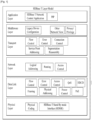
- FIG. 1 illustrates an exemplary layer structure model of an HDBaseT network used in the embodiments of the present invention.
- the HDBaseT network is based upon an OSI (Open System Interconnection) reference model.
- OSI Open System Interconnection
- FIG. 1 shows a new type of network layer structure, wherein the HDBaseT technology is combined with the OSI reference model.
- the HDBaseT network consists of a Physical Layer as the first layer (L1), a Data Link Layer as the second layer (L2), a Network Layer as the third layer, a Transport Layer as the fourth layer, a Middleware Layer as the fifth layer, and an Application Layer as the sixth layer.
- the functions provided by the first layer include a Physical Coding function for transmitting a T-stream, a HDSBI (HDBaseT Stand By mode Interface) function, and so on.
- a Physical Coding function for transmitting a T-stream
- a HDSBI HDBaseT Stand By mode Interface
- the functions provided by the second layer include a Flow Control function, an Error Control function, an Access Control function, a QoS (Quality of Service) function, an HDCD (HDBaseT Configuration Database) function providing information on the configuration of an HDBaseT device, a Framing function, a Physical Addressing function, a Power Control function, a power controlling function via Ethernet (i.e., PoE (Power over Ethernet)) function.
- a Flow Control function an Error Control function, an Access Control function, a QoS (Quality of Service) function
- an HDCD HDBaseT Configuration Database
- Framing function Framing function
- Physical Addressing function Physical Addressing function
- Power Control function a power controlling function via Ethernet (i.e., PoE (Power over Ethernet)) function.
- PoE Power over Ethernet
- the functions provided by the third layer include a Logical Addressing function, a Routing function for transmitting optimized data, an Access Control functions, and so on.
- the functions provided by the fourth layer include a Flow Control function, an Error Control function, a Connection Control function, a Service Point Addressing function, a Segmentation/Reassembly function supporting the segmentation and assembly of upper level data, and so on.
- the functions provided by the fifth layer include a Legacy Device Configuration function providing information on a legacy device for supporting the legacy device, a function for communicating with other networks (i.e., Other Network View function), a function for deciding privacy levels for protecting data and priority levels of data (i.e., Privacy/Privilege function), and so on.
- a Legacy Device Configuration function providing information on a legacy device for supporting the legacy device
- a function for communicating with other networks i.e., Other Network View function
- a function for deciding privacy levels for protecting data and priority levels of data i.e., Privacy/Privilege function
- the functions provided by the sixth layer include an HDBaseT Network Control Application function for controlling the communication through the HDBaseT network, and a function of showing (or displaying) a multi-streamed moving picture by using a PIP (Picture in Picture) method.
- an HDBaseT Network Control Application function for controlling the communication through the HDBaseT network
- a function of showing (or displaying) a multi-streamed moving picture by using a PIP (Picture in Picture) method PIP (Picture in Picture) method.
- the HDBaseT devices used in the embodiment of the present invention may transmit and receive data and streams based upon the layer model structure of FIG. 1 .
- the HDBaseT Adaptor (hereinafter referred to as a T-Adaptor) converts diverse types of protocol/interface/application data formats to HDBaseT data formats, and vice versa.
- the T-Adaptor uses a T-network (a network used by the HDBaseT) for performing communication with other T-Adaptors, and a destination (or target) T-Adaptor may recover a converted HDBaseT system stream (hereinafter referred to as a T-stream) to the initial format.
- T-network a network used by the HDBaseT
- T-Adaptor may recover a converted HDBaseT system stream (hereinafter referred to as a T-stream) to the initial format.
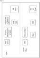
- FIG. 2 illustrates the structure and functions of an HDBaseT adaptor used in the embodiments of the present invention.
- a T-Adaptor used in the HDBaseT system may include at least one of an end node (e.g., a Dongle), an HDMI selector, and a USB Selector.
- an end node e.g., a Dongle
- an HDMI selector e.g., a USB Selector
- the T-Adaptor includes end nodes (e.g., Dongles), and the functions of the T-Adaptor includes a Source Discovery function, a device identifier mapping function (i.e., a Device ID to HDMI/Ethernet/USB ports mapping function), a Tx Adaptor control function using HDMI-CEC, an HDMI Selector, a USB Selector, and so on.
- the end node included in the T-Adaptor may support an HDCD (HDBaseT Configuration Database), a Power over Ethernet function, an Ethernet port, an HDMI port, and a USB (1.0/2.0/4.0) port.
- HDCD HDBaseT Configuration Database
- the T-Adaptor may include at least one or more HDMI input ports.
- the T-Adaptor may use an HDMI switching technique so as to connect HDMI data from a Source Device to Sink Device, which is connected to another T-Adaptor (i.e., an Rx Adaptor).
- the HDMI Selector may select one or more HDMI input ports based upon a control of an HDMI-CEC (Consumer Electronics Control) interface according to user settings. This will be referred to as HDMI selection.
- HDMI-CEC Consumer Electronics Control
- the T-Adaptor may include one or more USB ports. Depending upon the user settings, the T-Adaptor may select one of the USB ports, and this process may be performed by the USB selector included in the T-Adaptor.
- a single stream T-Adaptor supports a peer to peer connection with another adaptor within the HDBaseT network.
- the T-Adaptor may enable a CP (Control Point) to use the Legacy Network and may enable the HDMI switch to be controlled.
- CP Control Point
- the main functions of the T-Adaptor that is used in the HDBaseT system include HDMI switching, a Source Discovery function for finding a source device connected to the HDMI port and/or USB port of the T-Adaptor, a Port Mapping function for selecting a USB port based upon the HDMI port selection, and so on.
- the Source Discovery function refers to a function enabling the T-Adaptor to discover which source device is actually connected (or fixed) to the port included in the T-Adaptor itself.
- the T-Adaptor is unaware of the actual device name of the device that is connected to the HDMI port, Ethernet port, and USB port.
- the device name is directly (or personally) allocated (or assigned) by the user.
- the T-Adaptor may use HLIC (HDBaseT Link Internal Controls) acquisition/set up processing procedures (e.g., HLIC Get Transaction/HLIC Set Transaction) including a Device Description String.
- HLIC HDBaseT Link Internal Controls
- the port mapping function refers to a function of mapping a Device Identifier to an HDMI port, an Ethernet port, and a USB port. Based upon the selection of a source device identifier, the T-Adaptor may select the corresponding HDMI/Ethernet/USB ports as a port group. A USB Hub may be included in a reception T-Adaptor attached (or connected) to the USB port.
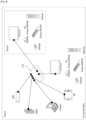
- FIG. 3 illustrates an exemplary HDBaseT network (T network) used in the embodiments of the present invention.
- the HDBaseT Network (hereinafter, T Network) may provide predictable and stable services with high efficiency and low delay.
- the T-Adaptor may provide adequate HDBaseT services through a Switch Device and through a connection group of Daisy Chain Devices, which support the serial connection method. For example, in accordance with the requirements of a native Protocol/Interface/Application, the T-Adaptor may select the adequate T-service through the Switch Device and the Daisy Chain Device. At this point, the Switch Devices and the Daisy Chain Devices are not required to be informed of the T-Adaptor type and the message processing method.
- the T-Network corresponds to a region to which an HDBaseT stream that is converted from the T-Adaptor is transmitted.
- the T-Network refers to a communication region from the source T-Adaptor to a sink T-Adaptor.
- Tx Adaptor transmission adaptor
- Rx Adaptor reception adaptor
- the Tx Adaptor may be identically used as the Source Adaptor
- the Rx Adaptor may be identically used as the Sink Adaptor. More specifically, depending upon the transmission format of a stream, a T-Adaptor may perform the function of a Tx Adaptor and the function of an Rx Adaptor.
- the HDBaseT-Stream (hereinafter, T-Stream) refers to a group of HDBaseT packet streams corresponding to information belonging to a native session. Each of the packets belonging to a T-Stream includes the same SID tokens.
- the T-Stream may optionally include different types of packets.
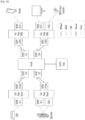
- FIG. 4 illustrates a 4-level hierarchical reference method and an identifier structure, which are used for identifying HDBaseT entities as an embodiment of the present invention.
- one HDBaseT device may have one or more Port Devices. And, each Port Device may have one or more T-Groups (HDBaseT Group). Also, each T-Group may have one or more T-Adaptors.
- T-Group may have one or more T-Adaptors.
- the 4-level hierarchical reference method may be performed by using a Device MAC Address for identifying management (or control) entities (i.e., Port Device Management Entity (PDME), Switch Device Management Entity (SDME), Control Point Management Entity (CPME)) that are included in an HDBaseT Device, a Port Identifier (Port ID) for identifying each port, a T-G Identifier (T-G ID) for identifying each T-Group, and a Type Mask being a unique mask for identifying each T-Adaptor.
- PDME Port Device Management Entity
- SDME Switch Device Management Entity
- CPME Control Point Management Entity
- a Device Identifier (Device ID) is used for identifying the HDBaseT Device.
- an Ethernet MAC Address may be used as the Device ID, and this may be referred to as the Device MAC Address.
- the Device MAC Address corresponds to a unique identifier for identifying management (or control) entities included in the corresponding HDBaseT Device.
- the PDME Port Device Management Entity
- SDME Switching Device Management Entity
- CPME Control Point Management Entity
- Ethernet Termination In case the PDME is used as the Ethernet Termination, the Ethernet MAC Address may be used as the unique identifier.
- HLIC HighBaseT Link Internal Controls
- the PDME uses an HLIC (HDBaseT Link Internal Controls) processing procedure so as to communicate with its link partner, the SDME. Also, by deducing (or deriving) the Device ID of the SDME, the PDME may borrow (or adopt) the identifier of the SDME.
- HLIC HighBaseT Link Internal Controls
- the PDME may use the SDME MAC Address as the Device ID of the PDME and may also use the Port Index of the SDME as the Port Index of the PDME.
- the Link Partner SDME shall deliver all control (or management) processing procedures to the PDME. If the link partner does not correspond to a switch of a direct point (i.e., peer to peer), the PDME cannot have a unique identifier.
- Port Referencing (Device ID: Port ID) is required for uniquely identifying the PDME.
- a Linkage between the T-Network and an E-Network may be configured, and the management (or control) of the T-Network and sessions using Ethernet communication may this be performed.
- a Port Identifier (ID) field is used for identifying a Port Device
- a T-G Identifier (ID) field is used for identifying a T-Group.
- the Port ID field and the T-Group field may be collectively used, both fields configuring a total size of 2 bytes (each field being configured of 10 bits and 6 bits).
- both the Port ID and the T-G ID may be referred to as a TPG Identifier (ID) (or a Group Port ID).
- the 2 bytes of the TPG ID field may accompany a 10-bit index of the Port Device and 6-bit T-Group index within the Port Device.
- the Port Indexes ranging from 1 to 1023, each having a value other than 0, provide a unique reference for the Port Device within the HDBaseT Device.
- the T-Group indexes ranging from 1 to 63, each having a value other than 0, provide a unique reference for a specific T-Group within the Port Device.
- the TPG ID when the T-Group Index is equal to 0, the TPG ID provides a unique reference for a port within the HDBaseT and may be referred to as the Port ID. In case the Port ID is equal to 0, the TPG ID cannot provide any significant value.
- Each T-Group may have one or more T-Adaptor type mask field indicating the T-Adaptor type associated to the corresponding group.
- the basic type mask field corresponds to a 16-bit sized field, and each bit indicates a specific type of a T-Adaptor associated with the corresponding T-Group.
- Table 1 shown below indicates exemplary bit indexes of a type mask field corresponding to each T-Adaptor type.
- Bit Indexes 0 and 1 respectively indicate an HDMI Source Device and a Sink Device.
- Bit Indexes 4 and 5 respectively indicate a USB Host and a USB Device/Hub.
- Bit Indexes 8 and 9 respectively indicate an S/PDIF Source and a Sink.
- Bit Indexes 12 and 13 respectively indicate an IR Transmission end (Infra-Red Tx) and an IR Reception end (Infra-Red Rx), and Bit Index 14 indicates a UART (Universal Asynchronous Receiver/Transmitter).
- Bit Index 15 indicates that an additional extension field of 16 bits is additionally used in order to indicate the T-Adaptor type.
- the HDBaseT Device does not assume that Index 15 is always set to 0.
- the HDBaseT Device may support up to 3 extension fields.
- the HDBaseT Device may support a Type Mask field of up to 64 bits.
- the Type Mask field may uniquely identify only the specific T-adaptor instance within the T-Group. Also, by using the type mask reference according to the present invention, one or a plurality of T-Adaptor instances may be referred to by the T-Adaptor group associated with the T-Group.
- FIG. 4 discloses a hierarchical reference method for identifying a T-Adaptor by using 10 bytes. More specifically, when a T-stream is transmitted from a Source T-Adaptor to a Sink T-Adaptor, a message (or stream) including a 10-byte Source T-Adaptor identifier and a 10-byte Sink T-Adaptor identifier may be transmitted.
- an 8-byte Source identifier e.g., a 6-byte Device Identifier + a 2-byte TPG Identifier
- an 8-byte Sink Identifier may be used in an HD-CMP message, which is used in a communication between a PDME of an HDBaseT end node and an SDME of an HDBaseT switch.
- the Type Mask is used to distinguish the interface of the port.
- the Type Mask is used for distinguishing each interface.
- the Type Mask may also be used in a case where a specific interface is designated within the T-Group Port Identifier when forming a session. For example, when a session is formed between two ports by using HD-CMP messages, the Type Mask may also be used when indicating the Source and Sink within the HD-CMP messages.
- FIG. 5 illustrates an exemplary session routing according to an embodiment of the present invention.
- a session defines a two-way communication and a path of a communication network, and pre-decides the adequate services included therein.
- the term session may be used in combination with the term Link.
- Each of the activated session is identified by an SID token (i.e., Session ID or Stream ID), which is accompanied in each HDBaseT Stream.
- SID token i.e., Session ID or Stream ID
- HDBaseT Switches which are included in the network path (hereinafter referred to as T-Switches) switch packets in accordance with the SID tokens.
- the beginning or initiation of a session corresponds to configuring and establishing a communication network path of a session for exchanging HDBaseT data.
- the Termination of a session refers to releasing (or deactivating) the communication network path for stopping (or terminating) the data exchange.
- the methods for setting up reception and transmission paths of a data stream from a Source Device to a Sink Device may be referred to as Session Routing.
- the HDBaseT Network may include one or more Source Devices (e.g., BDP, XBOX, camcorder or computer, and so on), one or more Sink Devices (e.g., TV or monitor, and so on), and one or more switches.
- Source Devices e.g., BDP, XBOX, camcorder or computer, and so on
- Sink Devices e.g., TV or monitor, and so on
- switches e.g., switches.
- session routing indicates setting up a path for transmitting Session Data from a BDP, which is a Source Device, to a TV set up in the living room, which is a Sink Device, among the many HDBaseT Links formed in the HDBaseT network.
- HDBaseT paths supporting the Type 3 reference method may be configured in the HDBaseT Network.
- the Type 1 reference method uses only a Device Identifier (Device ID or Ethernet MAC Address)
- the Type 2 Reference method uses a Device Identifier and a T-Group identifier
- the Type 3 Reference method uses the 4-layer reference method described in FIG. 4 .
- each of the HDBaseT devices may adaptively use the Type 3 Reference method.
- FIG. 6 illustrates one of the exemplary applications of a switch according to an embodiment of the present invention.
- a switch corresponds to one of the HDBaseT devices required for performing session routing.
- the HDBaseT Network has been designed in order to connect multiple electrical appliances through a single network in a regular household.
- a switch may deliver session data (i.e., T-Streams) from one or more Source Devices to one or more Sink Devices.
- Session Data being transmitted from a Source Device e.g., BDP, XBOX, computer, mobile station (MS), and so on
- a Display Device e.g., TV
- FIG. 7 illustrates a Daisy Chain method used in the embodiments of the present invention.
- an IP TV Internet Protocol TV
- Src 1 Source Devices BDP
- XBOX Src 2
- PC Src 3
- an Ethernet interface and an HDBaseT Sink interface may be realized in the IP TV, and at least one or more of an Ethernet interface, HDBaseT Source Interface, and an HDBaseT Sink interface may be realized in the Source Devices.
- the PC may be connected to the Internet through a modem.
- an Ethernet routing performance may be supported in order to access an internet service through a BDP and/or IP TV, which is/are connected to the HDBaseT Daisy Chain Link.
- HDBaseT Uplink Stream (US) and/or Downlink Stream (DS) packets carrying an Ethernet payload may be identified by a packet type code included in the packet header field.
- the T-Adaptor included in the HDBaseT Device may depacketize all HDBaseT packets carrying an Ethernet payload. At this point, each HDBaseT Device decides an Ehternet packet transmission path based upon an Ethernet Routing Table.
- entities having an ELV structure may periodically use an HLIC (HDBaseT Link internal Controls) Get/Set Transaction between HDBaseT Daisy Chain devices.
- HLIC HDBaseT Link internal Controls
- FIG. 7(b) illustrates another exemplary Daisy Chain method. Referring to FIG. 7(b) , it can be verified that a transmitter of the BDP and a receiver of the PC are connected to one another through an HDBaseT interface, and that the PC and the TV are connected to one another through an HDBaseT interface.
- Source Devices may include an Ethernet Switching Entity for switching Ethernet data, a T-Adaptor for converting HDBaseT streams and native data (e.g., HDMI data, USB data, or Ethernet data, and so on), and a Switching Entity for switching HDBaseT data depending upon the control of a control point.
- Ethernet Switching Entity for switching Ethernet data
- T-Adaptor for converting HDBaseT streams and native data
- native data e.g., HDMI data, USB data, or Ethernet data, and so on
- Switching Entity for switching HDBaseT data depending upon the control of a control point.
- Source Devices may include a Receiver for receiving HDBaseT data and a Transmitter for transmitting HDBaseT data. At this point, the receiver may output HDBaseT session data and Ethernet session data, and the transmitter may receive HDBaseT session data and Ethernet session data.
- the T-Adaptor may provide Power to legacy devices, and the transmitter may deliver power to the receiver, and the receiver may receive power from the transmitter.
- Sink Devices may include a receiver for receiving data and a T-Adaptor.
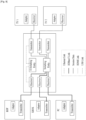
- FIG. 8 illustrates an exemplary switch structure according to an embodiment of the present invention.
- Multiple Stream HDBaseT Devices may support an HDBaseT Star within the HDBaseT network along with other Dongles, T-Adaptors, and switches.
- the switch may support legacy devices so that the CP (Control Point) can use legacy devices, such as Ethernet, USB, CEC, and so on.
- An, HDBaseT Switch (T-Switch) may have one or more HDBaseT Ports.
- the T-Switch may set up a data path for another Sink Device from a Source Device, and the T-Switch may deliver HDBaseT Data through the set up path. This is referred to as HDBaseT Switching.
- HDBaseT Switching may be controlled by an HDBaseT Contorl Point (CP), which is designated by an HDMI-CEC and/or the user.
- CP HDBaseT Contorl Point
- the Switch may include one or more Input Ports receiving an HDBaseT Stream, one or more Output Ports for transmitting the HDBaseT Stream, one or more packetizers for converting and recovering native data (e.g., HDMI data, USB data, Ethernet data, etc.) transmitted from the legacy devices to HDBaseT Streams, and Ethernet Swtiching Unit for switching Ethernet data, a Grooming Unit for categorizing different types of input signals (or data) by service types or destination and transmitting the categorized signals (or data), and a Switching Fabric Link Scheduler for switching HDBaseT Streams.
- native data e.g., HDMI data, USB data, Ethernet data, etc.
- Ethernet Swtiching Unit for switching Ethernet data
- Grooming Unit for categorizing different types of input signals (or data) by service types or destination and transmitting the categorized signals (or data)
- Switching Fabric Link Scheduler for switching HDBaseT Streams.
- the Switch of FIG. 8 may further include a Control Point Protocol Entity managing control commands that are transmitted from the control points, an HD-CMP (HDBaseT Control and Management Protocol) Entity, and an HDCD (HDBaseT Configuration Database) Entity.
- the HD-CMP entity may support control point signaling for Device Discovery, Link Discovery, Video/Audio Route Discovery/Set-up/Release, and HDBaseT Switching control.
- FIG. 9 illustrates another exemplary switch structure according to an embodiment of the present invention.
- the Switch may include an Ethernet Switching Entity, a Switching Entity, one or more Transmitter, and one or more Receivers.
- BDP, XBOX, and PC, and so on, which correspond to Source Devices may include a T-Adaptor and a transmitter
- TVs, and so on, which correspond to Sink Devices may include a T-Adaptor and a receiver.
- the T-Adaptor may convert native data, such as HDMI session data, USB session data, and Ethernet session data, to HDBaseT session data, or the T-Adaptor may convert HDBaseT session data to native data. Also, the T-Adaptor may provide power to the legacy devices.
- the Switching Entity may receive HDBaseT session data, which include HDMI, USB, or Ethernet session data. Also, the Switching Entity may correspond to control messaged transmitted from the Control Points, and sessions may be adequately configured based upon the control messaged and channel status.
- the Switching Entity may perform the functions of Session Generating, Network Access Control HDBaseT Switching, USB Switching, Sink Discovery, Source Discovery, Session ID Manager, and Control Point Manager.
- the Ethernet Switching Entity may switch Ethernet session data.
- the HDBaseT devices disclosed in the present invention may provide Full HD Multimedia, Ethernet, and Control signals through a single cable at the same time.
- the Source device may deliver uncompressed HD streaming to the Sink Device without any delay.
- the user may control from a room a Source Device or Sink Device positioned in another room through the HDMI-CEC.
- handover may be performed quickly and easily on the contents.
- FIG. 10 illustrates a method for performing session routing through a switch according to an embodiment of the present invention
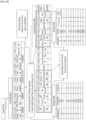
- FIG. 11 illustrates an updating procedure for a routing table and a device connection table.
- the HDBaseT network may include a Source Device (e.g., BDP, XBOX, etc.), an End Node Source (or End Node of the Source Device), a Switch, a Control Point, an End Node Sink (or End Node of the Sink Device), and a Sink Device (e.g., Monitor, TV, Game Controller).
- a Source Device e.g., BDP, XBOX, etc.
- an End Node Source or End Node of the Source Device
- a Switch e.g., a Control Point
- an End Node Sink or End Node of the Sink Device
- a Sink Device e.g., Monitor, TV, Game Controller
- the Switch may perform a Device Discovery function (e.g., Node Status Update, Link Status Update, etc.), a Bandwidth monitoring and assignment (or allocation) function, an HDBaseT Session Data Switching function, and an HDBaseT Control Point Protocol function. Also, the switch may acquire link information, switching/ routing information, source/sink discovery and control point information from the HDCD.
- control point may control the path for AV (Audio/Video) and control data.
- AV Audio/Video
- an HDBaseT Session Routing method for 2 HDBaseT Sources e.g., BDP, XBOX
- 2 HDBaseT Sinks Monitoring, TV
- an AV Stream can only be transmitted from the Source Device, and End Node Sink cannot transmit the AV stream.
- the End Node Source cannot be the End Node Sink.
- the HDBaseT link supports one-way AV streaming and two-way data networking.
- An HDBaseT connection may be set up when an HDBaseT link path of the source node and the destination of the stream are configured by the HDBaseT Switch.
- An HDBaseT connection request is blocked (1) when the HDBaseT link and the destination of the stream are not discovered, (2) when damage or loss occurs in one or more HDBaseT link paths, and (3) when one or more HDBaseT link paths are incapable of providing a sufficient bandwidth with respect to the HDBaseT connection request.
- the switch manages the bandwidth allocation (or assignment) with respect to the HDBaseT link and also manages an HDBaseT Routing Table, which is based upon a Link Status Algorithm. Before the data are transmitted, the switch sets up the path for each stream request.
- An HDBaseT packet carries a stream identifier and a destination address. All switches existing within the path maintain a "Link Status" and exchange "Link Status" with other HDBaseT devices.
- the switch supports one AV streaming for each HDBaseT port, and the switch cannot combine two or more AV streams by using a single AV Stream ID.
- An HDBaseT Stream Holding Time may be controlled by the HDBaseT Control Point.
- the size (or capacity) of each HDBaseT Link is equal to one another.
- FIG. 10 when a switch is turned on an initialized, the switch verifies the status of the available ports, links, and the switch. Then, the switch configures a Switching Routing Table (ref. FIG. 11(a) ). In FIG. 11(a) , the current switch corresponds to when the power has just been turned on. Therefore, only its available input port is recorded in the Routing Table.
- the end node configures an available initial port and link. Also, an end node discovery procedure may be performed.
- the End Node reports an initial node status, port status, and/or link status to the switch.
- the switch reconfigures a port based upon the initial node status, port status, and/or link status received from the end nodes, thereby updating the switch routing table (Ref. FIG. 11(b) ).
- the switch since the switch receives the initial node status, port status, and/or link status from a Source End node, the identifier of the Source node and the identifier of an HDBaseT stream, which is received from the source, may be updated in the Routing table.
- the CP When the power of the Control Point (CP)is turned on, the CP may set up an initial status (or state). Also, the CP verifies the port status, link status, and switch status related to the CP itself and, then, the CP configures a device connection table (Ref. FIG. 11(d) ). In FIG. 11(d) , since the CP recognizes that the current BDP and XBOX operate as the Source nodes, the CP assigns Source node identifiers to the Device connection table.
- control point performs an HDBaseT switch device discovery procedure.
- the CP may configure an Ethernet and a TCP/IP, and the CP may also receive a device connection table from the switch. Thereafter, the CP transmits a control command to the switch and waits (or stands-by) for a response.
- the switch After receiving the control command, the switch calculates an HDBaseT Routing path and may reconfigure the ports. Also, in order to set up a routing path and to assign a bandwidth, the switch transmits control messages to the end nodes and updates a switch routing table (Ref. FIG. 11(c) ). In FIG. 11(c) , the switch updates the destination identifier and output port identifier in the routing table based upon the routing path.
- the CP updates the Device Connection table (Ref. FIG. 11(e) ). More specifically, the CP may update the identifier of the Sink Device within the Device Connection Table.
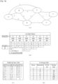
- FIG. 12 illustrates an exemplary method for updating a link status according to an embodiment of the present invention.
- Alphabets A, B, C, D, E, and F represent nodes, and the connection line between each node represents the link. Also, the numbers marked on the connection lines may indicate the bandwidth of the link or the delay coefficient. More specifically, the Link Status packet represents the link connection status between each node.
- the switch By periodically transmitting and receiving a Device Status packet or a Device status request message and a Device status response message the switch, information on the neighboring nodes (e.g., Sink Node and Source Node) and information on the activated link may be searched. Also, the switch may calculate and allocate (or assign) bandwidths for the neighboring nodes.
- the neighboring nodes e.g., Sink Node and Source Node
- the switch may calculate and allocate (or assign) bandwidths for the neighboring nodes.
- the switch In order to provide information on the bandwidth to the nodes, the switch generates (creates) a Link State (or status) Packet and may send the generated link state packet to all of the nodes existing in the HDBaseT Network via unicast or broadcast.
- Each of the nodes may generate a Link State (or status) Database indicating the topology of the entire network based upon the link status packet. Also, the nodes may use a Dijkstra algorithm so as to calculate the shortest path.
- the session routing method may include a Link State (or Status) Routing method and a Distance Vector Routing method.
- the router In case of the Distance Vector Routing method, all routers are aware of the neighboring nodes that are physically connected to one another and the Link Cost respective to the neighboring nodes. By exchanging the link information between the neighboring nodes, the router may repeatedly calculate the route path.
- the Distance Vector Routing method in case the Distance Vector node propagates an erroneous (or incorrect) path value, the error can be easily propagated to other nodes.
- FIG. 13 illustrates one of the HDBaseT session routing methods according to an embodiment of the present invention.
- the switch and/or nodes within the HDBaseT Network monitor the link status and may discover an optimal path in accordance with the monitored link status.
- the Link Status Routing method may be applied to the HDBaseT Session Routing method. After receiving the Link Status Request message, each of the HDBaseT devices transmits Local connectivity information, such as Link Status, to a Routing Processor of other devices.
- Local connectivity information such as Link Status
- the Routing Processor of each of the HDBaseT devices may gather and update the link status, may configure the entire network topology, and may calculate the path for all of the destinations by using the configured network topology. Since the routing processor is aware of the network topology, the dependence of the routing processor on other nodes during the routing calculation is low.
- the Routing Processor may also be referred to as an RPE (Routing Processor Entity), and the Routing Processor may be included in the HDBaseT devices. Referring to FIG. 13 , a case where the RPE is included in the switch will be described in detail.
- the Routing Processor and/or SDME of the Switch may calculate an optimal path from the source to the sink and may also calculate session routing information based upon the link status information.
- All of the HDBaseT devices carry a link status table, which indicates Global Topology Information and Link Cost Information.
- the Link Status Table may be set up and updated by exchanging Link Status Notification (or Notify) messages.
- the Link Status Notify messages include a transmission port identifier designating a specific HDBaseT Link, bandwidth information, and active session information and a reception port identifier.
- the HD-CMP packet or the HD-CMP packet within an HLIC is used for transmitting session routing information including information types, such as Link Status Notify messages, Session Initiate Request messages and Session Initiate Response messages, Session Route Request messages and Session Route Response messages, Session Release Request messages and Session Release Response messages, and so on.
- information types such as Link Status Notify messages, Session Initiate Request messages and Session Initiate Response messages, Session Route Request messages and Session Route Response messages, Session Release Request messages and Session Release Response messages, and so on.
- the HD-CMP packet within the HLIC allows the end node within an edge link of a sub network to exchange HD-CMP messages.
- FIG. 14 illustrates an exemplary session routing table format used in the embodiments of the present invention.
- a Routing table is used for managing session routing information of all transmission ports (Tx Ports) available to the HDBaseT devices. Based upon the path information from the source to the destination calculated by the routing processor entity (RPE), the RPE computes (or calculates) a transmission port identifier for each destination and may update the transmission port identifier of the session routing table belonging to the RPE itself.
- RPE routing processor entity
- the session routing table may be generated (or created) based upon an HDBaseT Link Status Routing Algorithm.
- the session routing table may include a 2-byte (or 2-octet) Sink Identifier field, a 2-byte transmission port identifier (Tx Port ID) field, a Routing Path Description Section field, and an assigned session identifier (Assigned Session ID) field.
- the Sink ID field indicates a device identifier identifying the Sink Device
- the Tx Port ID field identifies a transmission port of a device transmitting the corresponding message
- the Routing path represents path information starting from a source node to a sink node, which is designated by a PDS of an HD-CMP message.
- the Assigned Session ID field is used for identifying active sessions within the transmission port identifier of the HDBaseT device.
- the session routing table may be independently set up, maintained, and managed by source nodes, sink nodes, a switch, and/or T-Adaptors existing within the HDBaseT Network. For example, by periodically transmitting and receiving control information related to the routing table to and from each node, the switch may update the session routing table.
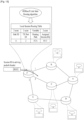
- FIG. 15 illustrates an exemplary link status updating method for setting up a route path according to an embodiment of the present invention.
- Each of the HDBaseT devices may manage Session Routing Information from valid Link Status Notify messages. Also, the Routing Processor or Routing Processor Entity (RPE) of each HDBaseT device may transmit a Link Status Request message, which requests for link information via Ethernet network or HDBaseT network, to other HDBaseT entities in the form of unicast or broadcast. However, each node is not required to periodically broadcast the link status information.
- RPE Routing Processor or Routing Processor Entity
- the Link Status information may be exchanged between the HDBaseT devices (i.e., Routing Processors). If a specific routing processor receives a Link Status Request message requesting for Link information from another routing processor, the specific routing processor shall transmit a Link Status response including all Link status information of all of the devices to the other routing processor.
- the HDBaseT devices i.e., Routing Processors.
- the HDBaseT device receives a new Link Status notify message from another HDBaseT device, the Link status information included in the link status notify information is reflected to the link status table, which is managed by the HDBaseT device.
- FIG. 15(a) illustrates an example of the link status request message and the link status notify message being transmitted and received within the HDBaseT network.
- a link status request message may be transmitted from a switch device having a device identifier of '6' to a source node, a sink node, a daisy chain, and other switches for session routing. Having received the link status request information, the source node, the sink node, the daisy chain, and the other switches delivers a link status notify message including a link status table, which is managed by each of the source node, the sink node, the daisy chain, and the other switches, to the routing processor of the corresponding switch. Based upon the link status information included in the link status notify message, the routing processor of the switch device may compute (or calculate) an optimal routing path.
- the link status information may include a Port information field with respect to a transmission port to a reception port (Tx to Rx Port Information field), a Bandwidth field indicating the bandwidth of the corresponding link, and an Active Session field indicating an activated session.
- FIG. 15(a) illustrates an example wherein the routing processor is provided in a switch having a device identifier of '6'
- the routing processor may also be provided in source nodes, sink nodes, and/or other switches.
- the routing processor calculates an optimized path from a source node to a sink node, and, based upon the acquired link status information, the routing processor delivers session routing information including information on the routing path starting from the source node to the sink node. For this, the routing processor configures and manages a link status table and a session routing table. Furthermore, based upon the routing path calculated from the source to the destination, the TX port for each target node is calculated, and the routing table may be updated accordingly.
- the routing processor uses the Dijkstra algorithm and the link status table so as to calculate the optimized routing path for all devices.
- the Link Cost is decided based upon the bandwidth assigned to each link or path delay.
- the session routing method uses the link status routing has a 3-level route selection priority level.
- a low cost (i.e., low assigned bandwidth and low congestion) level is based on an assigned bandwidth. If session data being assigned to a link do not exist, the link cost is equal to '0'.
- the link cost is based on the entire bandwidth of the corresponding link. At this point, the link cost is calculated as 1/(total bandwidth of the corresponding link).
- the link cost varies in accordance with the number of hops. If a device has a link (Tx Port) connected to another device, the cost of the corresponding link is equal to '1'.
- the 3-level route selection priority level is optional (or selective) and may be adaptively used in accordance with the user's request.
- FIG. 15(b) illustrates an exemplary Link Status Table structure.
- the link status table corresponds to link status information for managing a link status of the devices included in the HDBaseT Network.
- the link status notify packets are reflected on the link status table.
- the link status table may include a transmission device identifier (Tx Device ID) field identifying a sender transmitting (or sending) link status information, a transmission port identifier (Tx Port ID) field identifying a transmission port of the sender, a reception device identifier (Rx Device ID) for identifying a receiver, a reception port identifier (Rx Port ID) for identifying a reception port of the receiver, a Total Bandwidth field indicating the total bandwidth of the corresponding link, a Downstream bandwidth (Downstream BW) field indicating the bandwidth of a Downstream, an Upstream bandwidth (Upstream BW) indicating the bandwidth of an Upstream.
- Tx Device ID transmission device identifier
- Tx Port ID transmission port identifier
- Rx Port ID reception port identifier
- Total Bandwidth field indicating the total bandwidth of the corresponding link
- Downstream BW Downstream bandwidth
- Upstream BW Upstream bandwidth
- the link status table may further include a Length field indicating the total length of the link status table, a session identifier (Session ID) field identifying a session set up in the corresponding link, a Session Type field indicating the type of the corresponding session, and a Session Size field indicating the size of the corresponding session.
- Session ID session identifier
- Session Size Session Size
- the link status table may further include a source identifier (Source ID) field identifying a source device that provides contents, a source group identifier (Source Group ID) field identifying a source group, a source port identifier (Source Port ID) field identifying a port of the source device, a Sink identifier (Sink ID) field identifying a sink device that is being provided with contents, a sink group identifier (Sink Group ID) field identifying a sink group, a sink port identifier (Sink Port ID) field identifying a port of the sink device, and an Other Active Session field including information on other active sessions.
- FIG. 15(c) illustrates another exemplary Link Status Table.
- the Link Status Table of FIG. 15(c) is configured of a structure including only a transmission device identifier field, a transmission port identifier field, a reception device identifier field, a reception port identifier field, a total bandwidth field, a downstream bandwidth field, an upstream bandwidth field, and an active session identifier.
- the size of each field is difference from those of FIG. 15(b) .
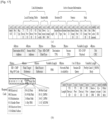
- FIG. 16 illustrates an exemplary link status request message structure used in the embodiments of the present invention.
- the Link Status request message is used for requesting Link status information of HDBaseT links.
- the Link Status Request message may be transmitted between both management entities within the HDBaseT Network in the form of an Ethernet message.
- the Link Status Request message may include a destination device identifier field (Destination MAC address field) for identifying a destination management entity to which the link status request message is directly delivered, a source device identifier field (Source MAC Address field) for identifying a management entity transmitting the link status request message, a type field indicating that the type of the link status request message is an HD-CMP Ethernet packet, a destination TPG field for identifying a port device of the destination, a source TPG field for identifying a port of the management entity transmitting the link status request message, and an HD-CMP payload.
- a destination device identifier field Destination MAC address field
- Source identifier field Source identifier field
- Type field indicating that the type of the link status request message is an HD-CMP Ethernet packet
- a destination TPG field for identifying a port device of the destination
- a source TPG field for identifying a port of the management entity transmitting the link status request message
- an HD-CMP payload
- the HD-CMP payload may include an HD-CMP message operation Code (HD-CMP Msg Op Code) field indicating that the message is being used for a link status request, a Final Target Reference (FTR) field, a Real Source Reference field, a PDS (Path Description Section) field indicating a path from the source node to the sink node, an NPA (Network Path Availability) field indicating an available network path, an SIQ (Session ID Query) field, and an Op Code U_SNPM body field, which is an HD-CMP payload.
- HD-CMP Msg Op Code HD-CMP message operation Code
- the HD-CMP Msg Op code field may include a Mod field indicating a method for delivering a session status request message to another device, and a Dir field indicating the direction to which the session initiate request message is being transmitted.
- the Mod field may indicate that the message is delivered to all ports connected to the corresponding device (00), that the message is delivered to a designated port so that the message can be delivered to a routing path known by the device (01), that the message is delivered to a designated port so that the message can be delivered to a single optimal routing path (10), or that the message is delivered to a path defined by the PDS field (11).
- the Dir field indicates the delivery direction of a message.
- the Dir field may indicate a downlink stream (DL) (01), an uplink stream (US) (10), or a two-way stream (mixed path) (11).
- the FTR (Final Target Reference) field is used for identifying a session partner (e.g., management entity of the final destination), which is to be finally transmitted through the HDBaseT Network
- the source reference field (RSR field) is used for identifying a first initiation (or initiate) entity, which has transmitted the session status request message.
- the final target reference field corresponds to an 8-bit field, which may include a MAC address identifying a management entity of a session partner, which corresponds to the destination, and a TPG identifier identifying a port device of the session partner.
- the source reference (RSR) field corresponds to an 8-bit field, which may include a MAC address of a management entity included in the initiation entity and a TPG identifier identifying the port device of the initiation entity.
- the Op Code U_SNPM body field may include a Link Status Request Type field indicating the type of the link status request, and a Device ID or Device MAC address for identifying the management entity of the source device.
- FIG. 17 illustrates structures of link status notification (or notify) messages used in the embodiments of the present invention.
- the routing processor entity (RPE) of the HDBaseT device may acquire Session Routing Information from a valid Link status notify message. At this point, the RPE reflects session routing information on the session routing table, which is managed by the RPE itself, thereby updating the session routing table.
- FIG. 17(a) illustrates an exemplary link status notify message structure.
- the link status notify message may include a sender identifier (Sender ID) field identifying the device transmitting the corresponding message, a Destination identifier (Destination ID) field identifying the subsequent destination device to which the message is to be transmitted, a message type (Msg Type) field indicating the type of the corresponding message, a transmission device identifier (Tx Device ID) field identifying a source device (e.g. BDP), a transmission port identifier (Tx Port ID) field identifying a transmission port of the source device, a reception device identifier (Rx Device ID) for identifying a sink device(e.g.
- reception port identifier for identifying a reception port of the sink device
- Total Bandwidth field indicating the total bandwidth of the corresponding link
- Downstream BW Downstream bandwidth
- Upstream BW Upstream bandwidth
- the link status notify message may further include a Length field indicating the total length of the link status notify message, a session identifier (Session ID) field identifying a session set up in the corresponding link, a Session Type field indicating the type of the corresponding session, and a Session Size field indicating the size of the corresponding session.
- the session type field indicates which of the HDMI data, Ethernet data, USB data, and/or IR data are included in the corresponding session.
- the link status notify table may further include a source identifier (Source ID) field identifying a source device that provides contents, a source group identifier (Source Group ID) field indicating a source group port number, when the corresponding session is coupled with another session, a source port identifier (Source Port ID) field identifying a session source port of the source device, a Sink identifier (Sink ID) field identifying a sink device that is being provided with contents, a sink group identifier (Sink Group ID) field indicating a sink group port number, when the corresponding session is coupled with another session, a sink port identifier (Sink Port ID) field identifying a port of the sink device, and an Other Active Session field including information on other active sessions.
- a source identifier (Source ID) field identifying a source device that provides contents
- a source group identifier (Source Group ID) field indicating a source group port number, when the corresponding session is coupled with another session
- a source port identifier (Source Port ID
- the source group port number when the source device supports session coupling, the source group port number may be set up as a non-zero value. And, when the sink device supports session coupling, the sink group port number may also be set up as a non-zero value.
- the Link Status Notify message may be configured of link information and active session information.
- the link information includes local routing table information and bandwidth information.
- the local routing table information includes a transmission device identifier field, a transmission port identifier field, a reception device identifier field, a reception port identifier field, and a total bandwidth field.
- the local routing table information is used for updating the routing table of each HDBAseT device.
- the active session information is configured of session identifier information, source device information, and sink device information.
- the session identifier information includes a length field, a session identifier field, a session type field, and a session size field.
- the source device information includes a source identifier, a source group identifier, and a source port identifier
- the sink device information include a sink identifier, a sink group identifier, and a sink port identifier field.
- FIG. 17(b) illustrates another exemplary link notify message structure.
- the link status notify message may include a Destination MAC address field for identifying a subsequent destination management entity to which the corresponding message is to be delivered, a source device (Source MAC Address) for identifying a management entity transmitting the link status request message, a type field indicating that the type of the link status request message is an HD-CMP Ethernet packet, a destination TPG field for identifying a port device of the destination, a source TPG field for identifying a port of the management entity transmitting the link status request message, and an HD-CMP payload.
- a Destination MAC address field for identifying a subsequent destination management entity to which the corresponding message is to be delivered
- a source device Source MAC Address
- a type field indicating that the type of the link status request message is an HD-CMP Ethernet packet
- a destination TPG field for identifying a port device of the destination
- a source TPG field for identifying a port of the management entity transmitting
- the HD-CMP payload may include an HD-CMP message operation code field (HD-CMP Msg Op Code) field indicating that the message is being used for a link status notify, a Final Target Reference (FTR) field, a Real Source Reference field, a Path Description Section (PDS) field indicating a path from the source node to the sink node, an NPA (Network Path Availability) field indicating an available network path, an SIQ (Session ID Query) field, and an Op Code U_SNPM body field, which is an HD-CMP payload.
- HD-CMP Msg Op Code HD-CMP message operation code field
- FTR Final Target Reference
- PDS Path Description Section
- NPA Network Path Availability
- SIQ Session ID Query
- Op Code U_SNPM body field which is an HD-CMP payload.
- the HD-CMP Msg Op code field may include a Mod field indicating a method for delivering a link status notify message to another device, and a Dir field indicating the direction to which the link status notify message is being transmitted.
- the Mod field may indicate that the message is delivered to all ports connected to the corresponding device (00), that the message is delivered to a designated port so that the message can be delivered to a routing path known by the device (01), that the message is delivered to a designated port so that the message can be delivered to a single optimal routing path (10), or that the message is delivered to a path defined by the PDS field (11).
- the Dir field indicates the delivery direction of a message.
- the Dir field may indicate a downlink stream (DS) (01), an uplink stream (US) (10), or a two-way stream (mixed path) (11).
- the FTR (Final Target Reference) field is used for identifying a session partner (e.g., management entity of the final destination), which is to be finally transmitted, and the source reference field (RSR field) is used for identifying an initiation (or initiate) entity, which initially transmits the link status notify message.
- the final target reference field corresponds to an 8-bit field, which may include a MAC address identifying a management entity of a session partner, which corresponds to the destination, and a TPG identifier identifying a port device of the session partner.
- the source reference (RSR) field corresponds to an 8-bit field, which may include a MAC address of a management entity included in the initiation entity and a TPG identifier identifying the port device of the initiation entity.
- the Op Code U_SNPM body field may include a Length field indicating the total length of the Op Code U_SNPM body field, a transmission device identifier (Tx Device ID) field identifying the transmission device, a transmission port identifier (Tx Port ID) identifying the transmission port of the transmission device, a device identifier (Rx Device ID) field of neighboring devices positioned in between, a reception port identifier (Rx Port ID) field indicating the reception port identifiers of the neighboring devices positioned in between, a Downlink stream bandwidth (Downstream BW) field indicating the available bandwidth of the downstream link, an Uplink stream bandwidth (Upstream BW) field indicating the available of the upstream link, and an Other Link information (Other Link Info.) field including information on other links.
- Tx Device ID transmission device identifier
- Tx Port ID transmission port identifier
- Rx Port ID device identifier
- Rx Port ID reception port identifier
- the Link Status Notify message may use a unicast SNPM (U_SNPM) packet so as to be transmitted between the management entities of the HDBaseT network.
- U_SNPM unicast SNPM
- the term session may be used as the same meaning as the term link.
- Link Status (or State) Message may be used as the same meaning as the term Session Status (or State) Message.
- FIG. 18 illustrates an exemplary session routing method according to an embodiment of the present invention.
- FIG. 18 illustrates a case where a session initiation if requested by the control point.
- the HDBaseT devices disclosed in the present invention may support DSR (Distributed Session Routing) method and CSR (Centralized Session Routing) method.
- FIG. 18 may be applied to all cases using the DSR method and the CSR method.
- the CSR method may be used in a case where the RPE (Routing Processor Entity) is realized in the CPME function of the HDBaseT network.
- RPE Centralized Session Routing
- the combination of the RPE and the CPME may verify and maintain the total topology and state (or status) of each link within the network.
- the combination of the RPE and the CPME may calculate an optimized path for each session and a valid session identifier (SID), when each session is being configured.
- SID session identifier
- the RPE/CPME combination may be realized in an end node, a switch, or a pure Ethernet device. Since the function of the RPE/CPME combination is capable of performing fast route/SID calculation, a session may be configured much more quickly.
- the RPE/CPME combination uses a Knowledge Base, and the RPE may provide session route calculation in accordance with the request made by the management entity.
- the RPE/CPME combination is configured in an end node (e.g., BDP or CP, etc.) and/or a switch.
- all HDBaseT devices that are currently available for access may be displayed on the screen of the control point (CP).
- the CP may select the HDMI source T-Adaptor of the BDP as the first partner entity, and the CP may select the HDMI Sink T-Adaptor of the TV as the second partner entity.
- the CP which corresponds to an initiation entity, may transmit a Session Initiate Request message including the session group identifier to the BDP (S1810).
- the Session Initiate Request message may include an HD-CMP Msg OpCode field, a FTR (Final Target Reference) field, a RSR field, a PDS (Path Description Section) field, an NPA (Network Path Availability) field indicating an available network path, an SIQ (Session ID Query) field, and an Op Code U_SNPM body field, which is an HD-CMP payload.
- the FTR (Final Target Reference) field is used for identifying a session partner (e.g., management entity of the final destination) that is to be transmitted
- the source reference field (RSR field) is used for identifying an initiation (or initiate) entity, which transmits the Session Initiate Request message.
- the final target reference field corresponds to an 8-bit field, which may include a MAC address identifying a management entity of a session partner, which corresponds to the destination, and a TPG identifier identifying a port device of the session partner.
- the source reference field corresponds to an 8-bit field, which may include a MAC address of a management entity included in the initiation entity and a TPG identifier identifying the port device of the initiation entity.
- the Final Target Reference (FTR) field may also be referred to as an FDER (Final Destination Entity Reference) field, and the source reference field may also be referred to as an RSER (Real Source Entity Reference) field.
- FDER Fluor Destination Entity Reference
- RSER Real Source Entity Reference
- the PDS field is included in the payload of the HD-CMP message, and the PDS field includes information of the PDS entities indicating the input port for each Device and the output port from each device. More specifically, the PDS field indicates the routing path from the source node to the sink node.
- the NPA field is included in the payload of the HD-CMP message, and the NPA field indicates the data size that can be processed and the number of accumulated streams.
- the SIQ field is used for searching activated/already assigned session identifiers from the network path.
- the final target reference field included in the Session Request message indicates the BDP, which corresponds to the final destination, and the source identifier field identifies the BDP, which corresponds to the Source device.
- the Sink identifier field may indicate the TV positioned in the living room, which corresponds to the display device.
- the CPME of the CP may determine all T-Adaptors that can be connected to the first partner (i.e., BDP) and the second partner (i.e., living room TV), so as to direct (or instruct) session configuration.
- the first partner i.e., BDP
- the second partner i.e., living room TV
- the BDP may operate as the Session initiator.
- the BDP may include a routing processor entity (RPE) that manages Global Link Status information and a routing table from the BDP to the TV. Accordingly, having receiving the Session Initiate Request message, the RPE of the BDP may calculate the routing path (S 1820).
- RPE routing processor entity
- the BDP may search for an optimized routing path in order to provide the contents to the living room TV, and the BDP may also transmit a Session Route Request message to each of the first switch (1st Switch), the second switch (2nd Switch), and the Living Room TV in order to connect the session (S1830).
- the 1st Switch, the 2nd Switch, and the Living Room TV may check the bandwidth for each session routing (S1835).
- FIG. 19 illustrates a method of checking a bandwidth for session routing according to an embodiment of the present invention.
- the initial state of the switch and/or the HDBaseT device corresponds to an Idle state (S1900).
- the switch and/or the HDBaseT device When the switch and/or the HDBaseT device receive(s) a Session Route Request message, the switch and/or the HDBaseT device verifies whether or not a Sink identifier field included in the session route request message is also included in the session routing table, which is managed by the switch and/or the HDBaseT device (S1910).
- the switch and/or the HDBaseT device verify (or verifies) whether or not a transmission port (Tx Port) exists (S1920).
- the switch and/or the HDBaseT device verify (or verifies) whether or not the upstream bandwidth is sufficient for routing the uplink stream data of the corresponding session (S1930), and the switch and/or the HDBaseT device also verify (or verifies) whether or not the existing transmission port supports a downstream bandwidth sufficient for routing the downlink stream data (S1940).
- the switch and/or the HDBaseT device transmit(s) a Session Route Response message, which includes ACK information, and zero OP Code (S1950).
- step S1910 If it is verified in step S1910 that the Sink identifier is not included in the Session Routing table, or if it is verified in step S1920 that a transmission port does not exist, or if it is verified in step S1930 that a sufficient upstream bandwidth is not provided, or it is verified in step S1940 that a sufficient downstream bandwidth is not provided, the switch and/or the HDBaseT device transmit(s) a Session Route Response message, which includes NACK information and non-zero OP code (S1960).
- the 1st Switch, the 2nd Switch, and the Living Room TV may transmit a Session Route Response message to the BDP.
- the Session Route Response message may further include information on an active session associated to the BDP.
- the 1st Switch, the 2nd Switch, and the Living Room TV respectively notify whether or not the transmission port and reception port of the 1st Switch, the 2nd Switch, and the Living Room TV are sufficient for routing the session data to the BDP through the Session Route Response message (S1840).
- the 1st Switch, the 2nd Switch, and the Living Room TV may update information on the configured session to each session routing tables belonging to the 1st Switch, the 2nd Switch, and the Living Room TV.
- a session between the BDP and the Living Room TV is configured by performing step S1830 and step S1840, and the BDP may transmit the HDMI data and/or IR data to the Living Room TV through the set up path (S1850).
- the BPD transmits a Session Initiation Response message to the control point (S1860).
- the Session Initiation Response message may include an HD-CMP Msg OpCode field, a FTR (Final Target Reference) field, a RSR field, a PDS (Path Description Section) field, an NPA (Network Path Availability) field indicating an available network path, an SIQ (Session ID Query) field, and an Op Code U_SNPM body field, which is an HD-CMP payload.
- the HD-CMP Msg OpCode of the Session Initiation Response message may include a Response Code.
- the Response code field corresponds to a 3-bit field, which indicates that a Session Initiation Request is successful (i.e., Success), or which indicates that a request is attempted from another device (i.e., redirection), or which indicates that the request is not completed due to the existence of an error and that a request may be re-attempted once the error is corrected (i.e., Sender Error), or which indicates that the request is not completed due to the existence of an error in the recipient and that a request may be re-attempted once the error is corrected (i.e., Receiver Error), or which indicates that the Session Initiation Request has failed that the request is not reattempted (i.e., Global Failure).
- the Final Target Reference (FTR) field may be used for identifying an initiation entity (i.e., CP), which has transmitted the Session Initiation message, and the Source reference (RSR) field may be used for identifying a Session Partner management entity (i.e., BDP), which transmits the Session Initiation Response message.
- the Final Target Reference field may include a MAC address identifying a management entity, which is included in the initiation entity, and a TPG identifier identifying a port device of the initiation entity.
- the source reference (RSR) field may include a MAC address identifying a management entity of a session partner, and TPG identifier identifying a port device of the session partner.
- the PDS field, the NPA field, and the SIQ field may perform the same functions and the PDS field, the NPA field, and the SIQ field included in the Session Initiation Request message.
- the Per Op Code U_SNPM Body field of the Session Initiation Response message may include a session identifier (Session ID) field uniquely identifying a session initiated by the Source device, and a Downstream session size (DS Session Size) field indicating the downlink stream data size of the session, which is indicated by the NPA field, and an Upstream session size (US Session Size) field indicating the uplink stream data size of the session, which is indicated by the NPA field.
- Session ID session identifier
- DS Session Size Downstream session size
- US Session Size Upstream session size
- the Per Op Code U_SNPM Body field may further include a Source identifier (Source ID) field indicating the identifier of a source device, which is selected by the control point (CP), a Source T-Group identifier (Source T-Group) field indicating the T-Group identifier of a source, when the corresponding session is coupled with another session, and a Source T-Adaptor mask field indicating the T-Adaptor mask of the T-Group of the source device.
- Source ID Source identifier
- Source T-Group Source T-Group identifier
- Source T-Adaptor mask indicating the T-Adaptor mask of the T-Group of the source device.
- the Per Op Code U_SNPM Body field may further include a Sink identifier (Sink ID) field indicating the identifier of a sink device, which is selected by the control point (CP), a Sink T-Group identifier (Sink T-Group) field indicating the T-Group identifier of a sink, when the corresponding session is coupled with another session, and a Sink T-Adaptor Mask field indicating the T-Adaptor mask of the T-Group of the sink device.
- a Sink identifier Sink ID
- Sink T-Group Sink T-Group identifier
- T-Group Sink T-Adaptor Mask
- the Source ID field, the Source T-Group field, and the Source T-Adaptor Mask field may be used for identifying the Adaptor of the source device, when a session is initiated.
- the Sink ID field, the Sink T-Group field, and the Sink T-Adaptor Mask field may be used for identifying the Adaptor of the sink device.
- the Source ID field, the Source T-Group Field, and the Source T-Adaptor Mask field may be used as a current Partner T-Adaptor Reference field (i.e., TPTR (This Partner T-Adaptor Reference) field), which indicates the T-Adaptor of a current session partner.
- TPTR This Partner T-Adaptor Reference
- the Sink ID field, the Sink T-Group field, and the Sink T-Adaptor Mask field may be used as a partner T-Adaptor reference field (i.e., OPTR (Other Partner T-Adaptor Reference) field), which indicates the T-Adaptor of another session partner.
- OPTR Ole Partner T-Adaptor Reference
- the BDP and the Living Room TV may report a Session Status Notify (or Notification) message, which includes Link Status Information on the HDBaseT Link, to the control point, either periodically or each time the state (or status) is changed.
- a Session Status Notify (or Notification) message which includes Link Status Information on the HDBaseT Link
- the Session Status Notify message of Fig. 8 is also called as the Link Status Notify message of Fig. 17 (S1870, S1880).
- the CP receiving the Session Status Notify message may be updated in the Session Routing Table of the CP itself based upon the session status information included in the Session Status Notify message.
- a session may be configured by Interface to Interface.
- a Session Initiation Request message including the Group ID and the Port ID may be transmitted to the Session Initiation Request message of step S1810.
- the user may designate a 1st partner, the BDP, and a 2nd partner, the T-Adaptor of the TV, with respect to the designated port, so as to request for an initiation of the session.
- a case where the RPE is provided in the CP can be assumed.
- an optimal path from the source device, BDP, to the sink device, Living Room TV may be calculated in advance from the RPE of the CP.
- the CP may transmit a Session Initiation Request message including information on the optimal route (or best route) path to the BDP.
- the process steps S1830 to S1840 of FIG. 18 may be omitted.
- the BDP may transmit a Link Status Request message requesting information on Link Status to the 1st Switch, the 2nd Switch, and the Living Room TV.
- the BDP may also receive a Link Status Response message including a Link Status table (ref. FIG. 15(c) ) from the 1st Switch, the 2nd Switch, and the Living Room TV.
- the Bandwidth verification process of step S1835 may be performed by the BDP. If a bandwidth sufficient for providing contents to the corresponding session can be provided, the BDP may transmit a Session Initiation Response message including ACK information and non-zero Op code to the CP.
- the Session Initiation Request message, the Session Initiation Response message, and the Session Status Notify messages may be transmitted through an HD-CMP message over the Ethernet, and the Session Route Request message and the Session Route Response message may be transmitted in an U_SNPM message format over the HDBaseT network.
- the Session Status Notify messages may also be transmitted over the HDBaseT network.
- FIG. 20 illustrates another exemplary session routing method according to an embodiment of the present invention.
- the CRS method is used is assumed in FIG. 20 .
- the RPE computes and selects the path (i.e., route selection). Therefore, in the CRS method, the Session Route Request message and the Session Route Response message are not required.
- the CP may calculate for initiating a session and a valid session identifier (SID).
- the CP may select a Blu-ray Disc player (BDP) as the first partner entity and may select the Living Room TV as the second partner entity. Therefore, in order to verify the session initiation availability and the requirements for session initiation of the first partner entity and the second partner entity, the CP may sequentially transmit the Session Initiation Request message to the BDP and the Living Room TV (S2010a, S2010b).
- BDP Blu-ray Disc player
- the BDP and the Living Room TV may receive a Session Initiation Response message including a reception acknowledgment (ACK) message (S2020a, S2020b).
- ACK reception acknowledgment
- the CP may transmit information of the selected best route and a new session identifier (SID) to the second partner entity (TV) through a Session Route Select Response message (S2030).
- SID session identifier
- the living room TV receiving the Session Route Select Response message may transmit a Session Route Set message, which includes information on the nest route and an initiated session identifier (SID) to the BDP through a second switch (2nd Switch) and a first switch (1st Switch) (S2040).
- SID session identifier
- the living room TV updates its own Session Routing table based upon the received Session Select Response message, and the 1st Switch, the 2nd Switch, and the BDP having received the Session Route Set message in step S2040 may update each Session Routing table based upon the received Session Route Set message.
- the BDP may transmit contents to the TV through a newly set session (S2050).
- the BDP may broadcast a Session Creation Completed message to all CPs within the HDBaseT network.
- the Session Creation Completed message may include an identifier for the newly created session (SID), and resource information on the selected PDS and corresponding session (S2060).
- the Session Initiation Request message, the Session Initiation Response message, the Session Route Select Response message, and the Session Created Completed message may be transmitted through the HD-CMP message over the Ethernet, and the Session Route Request (SRQ) message and the Session Route Set message may be transmitted in an U_SNPM message format within the HDBaseT Network.
- the structures of the Session Initiation Request message and the Session Response message are identical to the structures of the Session Initiation Request message and the Session Response message of FIG. 18 .
- the set up status of each field may be varied.
- FIG. 21 illustrates an exemplary session status updating method according to an embodiment of the present invention.
- Source Devices, Sink devices, and Switches are included in the HDBaseT Network.
- a Daisy Chain may be formed between the Switch and the source node or sink node.
- the corresponding devices are illustrates as a single block.
- each HDBaseT device is identified by each alphabet (A, B, C, ..., J) , and the small box inside each device represents a port (and/or T-Adaptor) provided in each device.
- Each of the HDBaseT entities creates and manages a Routing table and a Link Status table. Also, each of the HDBaseT entities may search for neighboring devices through an exchange of device status Request/response messages or through a periodic exchange of SNPM message. After verifying the neighboring devices and activated links, the HDBaseT entities may each create a Link Status Notify message and may transmit the created Link Status Notify message to a specific entity or to all entities within the network by using a broadcast method.
- Each of the HDBaseT devices may update a Link Status table based upon the Link Status information included in the Link Status Notify message. Reference may be made to FIG. 15(b) or FIG. 15(c) for the description of the Link Status table.
- FIG. 21 illustrates a case where an HDBaseT session (hereinafter referred to as T-Session) is created between source node A and sink node H. Reference may be made to FIG. 18 for the session creation procedure.
- source node A may transmit a Link Status Notify message, which includes link status information on the T-Session, to the devices within the HDBaseT Network.
- source node A may transmit a Link Status Notify message including a transmission device identifier field (A), a TX port identifier field (1), a reception destination identifier field (B), a Reception port identifier (2), a total bandwidth field (8), a downstream bandwidth field (3), and upstream bandwidth field (1), and a session identifier field (S1) identifying an active session (Ref. FIG. 21(a) ).
- A transmission device identifier field
- B reception destination identifier field
- S1 session identifier field
- Switch C may update its own Link Status table based upon the link status information included in the Link Status Notify message, which is transmitted from Daisy Chain B. Additionally, Switch C may also transmit a Link Status Notify message including Link Status information on its own Link Status table to Daisy Chain B, Sink Device E, and another Switch F, which are connected to Switch C (Ref. FIG. 21(c) ).
- Sink Device E may update its own Link Status table, and Sink Device E may transmit a Link Status Notify message including the updated Link Status table back to Switch C. At this point, may further include Link Status information associated to Switch C itself in the Link Status Notify message, thereby transmitting the corresponding message.
- FIG. 22 illustrates a method for managing a routing table and a link status table in a routing processor entity (RPE) supporting session routing according to an embodiment of the present invention.
- RPE routing processor entity
- the RPE calculates a best route from the source node to the sink node based upon the Link Status information and computes the Session Routing information.
- a Link Status information and a Session Routing table are required.
- the Link Status table includes Link Status information on all links available for access from a specific HDBaseT device. Additionally, a Session Routing table is used for managing Session Routing information on a transmission port (Tx Port) of a specific HDBaseT device.
- the RPE may transmit and receive a Session Connection Request message for managing a Link Status table and a Session Routing table.
- the RPE may perform a path computation function. More specifically, the RPE may use the Dijkstra algorithm and the Link Status table so as to compute a best route respective to all devices. Also, the RPE may compute a transmission port identifier (Tx Port ID) for each destination based upon the path information from the source device to the sink device, and RPE may also update the computed transmission port identifier on the Session Routing table, which is managed by the RPE itself.
- Tx Port ID transmission port identifier
- the RPE may be provided in any HDBaseT device.
- the RPE may be provided in a source node, a sink node, a Daisy Chain, and/or a control point (CP).
- CP control point
- the control point may transmit a Session Request message to the BDP, wherein the Session Request message indicates that the source device is the BDP, that the source group is '1', that the source port identifier is '1' (i.e., HDMI data), that the sink device is the TV, that the sink group is '1', and that the sink port is '1' (i.e., HDMI data).
- the Session Request message indicates that the source device is the BDP, that the source group is '1', that the source port identifier is '1' (i.e., HDMI data), that the sink device is the TV, that the sink group is '1', and that the sink port is '1' (i.e., HDMI data).
- the RPE of the BDP which has received the Session Request message, may calculate the best (or optimal) routing path by using the Dijkstar algorithm.
- the RPE may reflect the Link Status table so as to verify and update a minimum (or shortest) path from the Session Routing table, which is managed by the RPE itself.
- the RPE may verify a transmission port for an optimized path (or best path) for providing contents to the respective destination, the TV.
- the RPE may update the transmission port identifier on the Routing table.
- the RPE transmits a Session Route Request message including Session Routing information to all devices between the source node (BDP) and the destination (TV).
- the present invention may be applied to diverse home networks, home entertainment industries. And, most particularly, the present invention may also be applied to the HDBaseT system.
Landscapes
- Engineering & Computer Science (AREA)
- Computer Networks & Wireless Communication (AREA)
- Signal Processing (AREA)
- Multimedia (AREA)
- Automation & Control Theory (AREA)
- Data Exchanges In Wide-Area Networks (AREA)
- Small-Scale Networks (AREA)
Claims (11)
- Procédé de calcul d'un chemin de routage dans un réseau de transmission de base haute définition, HDBaseT ci-après, le procédé consistant à:transmettre, par un premier dispositif à un second dispositif, un message de demande d'état de liaison demandant des informations d'état de liaison;recevoir, par le premier dispositif en provenance du second dispositif, un message de notification d'état de liaison comprenant les informations d'état de liaison du second dispositif;mettre à jour, par le premier dispositif, une table d'états de liaison sur la base des informations d'état de liaison du second dispositif;calculer, par le premier dispositif, des informations de chemin de routage à partir d'un dispositif source à un dispositif récepteur sur la base de la table d'états de liaison; etcalculer, par le premier dispositif, des informations sur un port de transmission utilisé dans le chemin de routage sur la base des informations de chemin de routage,transférer, par le premier dispositif, de multiples flux vers le dispositif récepteur sur la base des informations de chemin de routage et des informations sur le port de transmission,dans lequel le premier dispositif et le second dispositif sont des dispositifs HDBaseT du réseau HDBaseT fournissant une transmission simultanée des multiples flux et une transmission de puissance par l'intermédiaire d'un seul câble,dans lequel les multiples flux comprennent des flux pour une communication bidirectionnelle,dans lequel les multiples flux comprennent un ou plusieurs parmi les flux de liaison descendante disponibles et les flux de liaison montante disponibles, etdans lequel le message de notification d'état de liaison comprend en outre un champ de bande passante descendante comprenant des informations sur une bande passante du flux de liaison descendante disponible et un champ de bande passante montante comprenant des informations sur une bande passante du flux de liaison montante disponible.
- Procédé selon la revendication 1, dans lequel le message de demande d'état de liaison comprend un champ de référence source, RSR, identifiant le premier dispositif, et un champ de référence cible final, FTR, indiquant une destination finale du message de demande d'état de liaison, et une charge utile de protocole de gestion de commande haute définition, HD-CMP, et dans lequel la charge utile de HD-CMP comprend un champ de section de description de chemin, PDS, définissant un chemin de routage à partir du dispositif source au dispositif récepteur.
- Procédé selon la revendication 2, dans lequel le message de demande d'état de liaison comprend en outre un champ de type de demande d'état de liaison indiquant un type de la demande d'état de liaison, et un champ d'identifiant de dispositif.
- Procédé selon l'une quelconque revendication 1 à 3, dans lequel la table d'états de liaison comprend:un champ d'identifiant de transmission configuré pour identifier le premier dispositif;un champ d'identifiant de port de transmission configuré pour identifier un port de transmission du premier dispositif;un champ d'identifiant de dispositif de réception configuré pour identifier le second dispositif;un champ d'identifiant de port de réception configuré pour identifier un port de réception du second dispositif;un champ de bande passante totale configuré pour indiquer une bande passante maximum d'une liaison;un champ de bande passante descendante configuré pour indiquer une bande passante disponible d'une liaison descendante;un champ de bande passante montante configuré pour indiquer une bande passante disponible d'une liaison montante; etun champ d'identifiant de session configuré pour indiquer un identifiant de session d'une session active associée au premier dispositif.
- Procédé selon l'une quelconque des revendications 1 à 4, dans lequel le premier dispositif comprend une entité de processeur de routage, et
dans lequel les informations de chemin de routage et les informations sur le port de transmission sont calculées par l'entité de processeur de routage. - Procédé selon l'une quelconque des revendications 1 à 5, dans lequel le premier dispositif correspondant à un commutateur, et
dans lequel le second dispositif correspondant à l'un parmi un noeud source, un noeud de réception, un autre commutateur, et un point de commande. - Dispositif de calcul d'un chemin de routage dans un réseau de transmission de base haute définition, HDBaseT, le dispositif comprenant:une entité de processeur de routage configurée pour calculer le chemin de routage;un port de transmission utilisé dans le réseau HDBaseT;un émetteur ; etun récepteur,dans lequel le dispositif est configuré pour:transmettre un message de demande d'état de liaison demandant des informations d'état de liaison au moyen de l'émetteur; etrecevoir un message de notification d'état de liaison comprenant les informations d'état de liaison au moyen du récepteur,dans lequel l'entité de processeur de routage met à jour une table d'états de liaison sur la base des informations d'état de liaison du message de notification d'état de liaison, calcule les informations de chemin de routage à partir d'un dispositif source à un dispositif récepteur sur la base de la table d'états de liaison, et calcule les informations sur le port de transmission utilisé dans le chemin de routage sur la base des informations de chemin de routage, etdans lequel le dispositif transfère de multiples flux vers le dispositif récepteur sur la base des informations de chemin de routage et des informations sur le port de transmission,dans lequel le dispositif est un dispositif HDBaseT du réseau HDBaseT qui fournit une transmission simultanée des multiples flux et une transmission de puissance par l'intermédiaire d'un seul câble,dans lequel les multiples flux comprennent des flux pour une communication bidirectionnelle,dans lequel les multiples flux comprennent un ou plusieurs parmi les flux de liaison descendante disponibles et les flux de liaison montante disponibles, etdans lequel le message de notification d'état de liaison comprend en outre un champ de bande passante de liaison descendante comprenant des informations sur une bande passante du flux de liaison descendante disponible et un champ de bande passante de liaison montante comprenant des informations sur une bande passante du flux de liaison montante disponible.
- Dispositif selon la revendication 7, dans lequel le message de demande d'état de liaison comprend un champ de référence source, RSR, identifiant le dispositif, et un champ de référence cible final, FTR, indiquant une destination finale du message de demande d'état de liaison, et une charge utile de protocole de gestion de commande haute définition, HD-CMP, et dans lequel la charge utile de HD-CMP comprend un champ de section de description de chemin, PDS, définissant un chemin de routage à partir du dispositif source au dispositif récepteur.
- Dispositif selon la revendication 8, dans lequel le message de demande d'état de liaison comprend en outre un champ de type de demande d'état de liaison indiquant un type de la demande d'état de liaison, et un champ d'identifiant de dispositif.
- Dispositif selon l'une quelconque revendication 7 à 9, dans lequel la table d'états de liaison comprend:un champ d'identifiant de transmission configuré pour identifier le dispositif;un champ d'identifiant de port de transmission configuré pour identifier le port de transmission;un champ d'identifiant de dispositif de réception configuré pour identifier un dispositif voisin du dispositif;un champ d'identifiant de port de réception configuré pour identifier un port de réception du second dispositif;un champ de bande passante totale configuré pour indiquer une bande passante maximum d'une liaison;un champ de bande passante descendante configuré pour indiquer une bande passante disponible d'une liaison descendante;un champ de bande passante montante configuré pour indiquer une bande passante disponible d'une liaison montante; etun champ d'identifiant de session configuré pour indiquer un identifiant de session d'une session active associée au dispositif.
- Dispositif selon l'une quelconque des revendications 7 à 9, dans lequel le dispositif correspond à un commutateur.
Applications Claiming Priority (4)
| Application Number | Priority Date | Filing Date | Title |
|---|---|---|---|
| US30696410P | 2010-02-23 | 2010-02-23 | |
| US30696310P | 2010-02-23 | 2010-02-23 | |
| US32773010P | 2010-04-26 | 2010-04-26 | |
| PCT/KR2011/001272 WO2011105815A2 (fr) | 2010-02-23 | 2011-02-23 | Procédé et appareil pour routage de session dans un système à réseau familial |
Publications (3)
| Publication Number | Publication Date |
|---|---|
| EP2540037A2 EP2540037A2 (fr) | 2013-01-02 |
| EP2540037A4 EP2540037A4 (fr) | 2017-01-04 |
| EP2540037B1 true EP2540037B1 (fr) | 2023-08-02 |
Family
ID=44476442
Family Applications (1)
| Application Number | Title | Priority Date | Filing Date |
|---|---|---|---|
| EP11747705.9A Active EP2540037B1 (fr) | 2010-02-23 | 2011-02-23 | Procédé et appareil pour routage de session dans un système à réseau familial |
Country Status (5)
| Country | Link |
|---|---|
| US (2) | US8593996B2 (fr) |
| EP (1) | EP2540037B1 (fr) |
| KR (1) | KR101414659B1 (fr) |
| CN (1) | CN102893558B (fr) |
| WO (1) | WO2011105815A2 (fr) |
Families Citing this family (38)
| Publication number | Priority date | Publication date | Assignee | Title |
|---|---|---|---|---|
| US9198084B2 (en) | 2006-05-26 | 2015-11-24 | Qualcomm Incorporated | Wireless architecture for a traditional wire-based protocol |
| US9398089B2 (en) | 2008-12-11 | 2016-07-19 | Qualcomm Incorporated | Dynamic resource sharing among multiple wireless devices |
| US9264248B2 (en) | 2009-07-02 | 2016-02-16 | Qualcomm Incorporated | System and method for avoiding and resolving conflicts in a wireless mobile display digital interface multicast environment |
| US8806094B2 (en) | 2009-09-25 | 2014-08-12 | Analogix Semiconductor, Inc. | Transfer of uncompressed multimedia contents or data communications |
| US8799537B1 (en) * | 2009-09-25 | 2014-08-05 | Analogix Semiconductor, Inc. | Transfer of uncompressed multimedia contents and data communications |
| US9582238B2 (en) | 2009-12-14 | 2017-02-28 | Qualcomm Incorporated | Decomposed multi-stream (DMS) techniques for video display systems |
| EP2540037B1 (fr) * | 2010-02-23 | 2023-08-02 | LG Electronics Inc. | Procédé et appareil pour routage de session dans un système à réseau familial |
| US9331962B2 (en) * | 2010-06-27 | 2016-05-03 | Valens Semiconductor Ltd. | Methods and systems for time sensitive networks |
| US20120131245A1 (en) * | 2010-11-19 | 2012-05-24 | Silicon Image, Inc. | Transfer of control bus signaling on packet-switched network |
| US9065876B2 (en) | 2011-01-21 | 2015-06-23 | Qualcomm Incorporated | User input back channel from a wireless sink device to a wireless source device for multi-touch gesture wireless displays |
| US20130013318A1 (en) | 2011-01-21 | 2013-01-10 | Qualcomm Incorporated | User input back channel for wireless displays |
| US8964783B2 (en) | 2011-01-21 | 2015-02-24 | Qualcomm Incorporated | User input back channel for wireless displays |
| US9413803B2 (en) * | 2011-01-21 | 2016-08-09 | Qualcomm Incorporated | User input back channel for wireless displays |
| US9787725B2 (en) | 2011-01-21 | 2017-10-10 | Qualcomm Incorporated | User input back channel for wireless displays |
| US10135900B2 (en) | 2011-01-21 | 2018-11-20 | Qualcomm Incorporated | User input back channel for wireless displays |
| US10108386B2 (en) | 2011-02-04 | 2018-10-23 | Qualcomm Incorporated | Content provisioning for wireless back channel |
| US9503771B2 (en) | 2011-02-04 | 2016-11-22 | Qualcomm Incorporated | Low latency wireless display for graphics |
| US9407507B2 (en) | 2011-08-30 | 2016-08-02 | Qualcomm Incorporated | Topology discovery in a hybrid network |
| US9495326B2 (en) | 2011-09-12 | 2016-11-15 | Qualcomm Incorporated | Providing communication path information in a hybrid communication network |
| US9525998B2 (en) | 2012-01-06 | 2016-12-20 | Qualcomm Incorporated | Wireless display with multiscreen service |
| JP6123212B2 (ja) * | 2012-10-02 | 2017-05-10 | セイコーエプソン株式会社 | 画像表示装置および画像表示装置の制御方法 |
| JP6426901B2 (ja) * | 2014-03-14 | 2018-11-21 | 富士通クライアントコンピューティング株式会社 | 配信方法、再生装置、配信装置、転送制御プログラムおよび配信制御プログラム |
| EP3222046A1 (fr) * | 2014-11-18 | 2017-09-27 | Caavo, Inc. | Paramétrage et commande en continu pour dispositifs de divertissement à domicile et contenu |
| WO2016148458A1 (fr) * | 2015-03-13 | 2016-09-22 | Samsung Electronics Co., Ltd. | Procédé pour maintenir une session miracast persistante sur une liaison sans fil |
| US10069727B2 (en) * | 2015-04-17 | 2018-09-04 | International Business Machines Corporation | Data packet retransmission processing |
| JP6516591B2 (ja) * | 2015-06-30 | 2019-05-22 | キヤノン株式会社 | 通信装置および表示装置 |
| JP6723734B2 (ja) * | 2015-12-09 | 2020-07-15 | キヤノン株式会社 | 通信装置、画像表示装置および通信制御プログラム |
| WO2018148439A1 (fr) | 2017-02-10 | 2018-08-16 | Caavo Inc | Détermination de signatures d'état pour des dispositifs électroniques client couplés à un commutateur audio/vidéo |
| JP6406558B2 (ja) * | 2017-03-07 | 2018-10-17 | パナソニックIpマネジメント株式会社 | 画像処理装置及びこれを備えた画像処理システム並びに電力制御方法 |
| US20180278514A1 (en) * | 2017-03-27 | 2018-09-27 | Juniper Networks, Inc. | Traceroute for multi-path routing |
| EP4191979A1 (fr) | 2017-07-14 | 2023-06-07 | Huawei Technologies Co., Ltd. | Procédé d'établissement d'un routage de segment pour un tunnel ipv6 |
| CN110650167B (zh) | 2018-06-26 | 2021-02-23 | 华为技术有限公司 | 通信方法和装置 |
| KR102304692B1 (ko) * | 2018-09-21 | 2021-09-24 | 주식회사 럭스로보 | 소스 코드 및 모듈 추천 시스템 및 모듈 어셈블리 |
| JP7284398B2 (ja) * | 2019-06-20 | 2023-05-31 | 富士通株式会社 | パケット解析プログラムおよびパケット解析装置 |
| WO2021136430A1 (fr) * | 2019-12-31 | 2021-07-08 | 中兴通讯股份有限公司 | Appareil et procédé de sélection de trajet, dispositif informatique et support lisible par ordinateur |
| CN113691639B (zh) * | 2020-05-19 | 2024-01-23 | 中移(成都)信息通信科技有限公司 | 端口标识解析的方法、装置、设备及存储介质 |
| US11637913B2 (en) * | 2020-07-15 | 2023-04-25 | Stryker Corporation | Automatic correspondence of encoders and decoders to video ports |
| CN113259182B (zh) * | 2021-07-02 | 2021-09-24 | 北京华云安信息技术有限公司 | 一种基于自主决策的通信路径监控方法及装置 |
Family Cites Families (20)
| Publication number | Priority date | Publication date | Assignee | Title |
|---|---|---|---|---|
| US4710917A (en) * | 1985-04-08 | 1987-12-01 | Datapoint Corporation | Video conferencing network |
| CA1337132C (fr) * | 1988-07-15 | 1995-09-26 | Robert Filepp | Systeme de reception pour reseau informatique interatif et sa methode de fonctionnement |
| US6215763B1 (en) * | 1997-10-29 | 2001-04-10 | Lucent Technologies Inc. | Multi-phase process for distributed precomputation of network signal paths |
| US6717956B1 (en) | 2000-03-03 | 2004-04-06 | Luminous Networks, Inc. | Dual-mode virtual network addressing |
| US7545755B2 (en) | 2000-03-03 | 2009-06-09 | Adtran Inc. | Routing switch detecting change in session identifier before reconfiguring routing table |
| JP3963690B2 (ja) * | 2001-03-27 | 2007-08-22 | 富士通株式会社 | パケット中継処理装置 |
| US7200144B2 (en) * | 2001-10-18 | 2007-04-03 | Qlogic, Corp. | Router and methods using network addresses for virtualization |
| US7873829B2 (en) * | 2002-11-06 | 2011-01-18 | International Business Machines Corporation | Offload processing for secure data transfer |
| US7545788B2 (en) * | 2004-08-20 | 2009-06-09 | At&T Intellectual Property I, L.P. | Methods, systems, and computer program products for modifying bandwidth and/or quality of service in a core network |
| CN100417070C (zh) * | 2005-05-30 | 2008-09-03 | 华为技术有限公司 | 一种内容计费实现方法和系统 |
| US8000318B2 (en) * | 2006-06-30 | 2011-08-16 | Embarq Holdings Company, Llc | System and method for call routing based on transmission performance of a packet network |
| KR100893159B1 (ko) * | 2007-01-25 | 2009-04-16 | 강릉원주대학교산학협력단 | 라우팅 방법 및 그에 따른 무선 네트워크 시스템 |
| US20090015723A1 (en) * | 2007-06-18 | 2009-01-15 | Sony Corporation Of Japan | Media switching device |
| KR100933365B1 (ko) * | 2007-09-28 | 2009-12-22 | 한국전자통신연구원 | 액세스 네트워크의 자원 관리 시스템 및 방법 |
| JP2009094832A (ja) * | 2007-10-10 | 2009-04-30 | Nec Access Technica Ltd | マルチキャストデータ配信装置、その配信方法およびその配信制御プログラム |
| CN101426004A (zh) * | 2007-10-29 | 2009-05-06 | 华为技术有限公司 | 三层会话的接入方法、系统及设备 |
| KR100924108B1 (ko) * | 2008-02-22 | 2009-10-29 | 성균관대학교산학협력단 | 링크 상태 갱신 시스템 및 그 제어방법 |
| EP2260636A1 (fr) * | 2008-02-29 | 2010-12-15 | Thomson Licensing | Procédés et appareils pour fournir une répartition de signal à équilibrage de charge |
| US8619775B2 (en) * | 2008-07-21 | 2013-12-31 | Ltn Global Communications, Inc. | Scalable flow transport and delivery network and associated methods and systems |
| EP2540037B1 (fr) * | 2010-02-23 | 2023-08-02 | LG Electronics Inc. | Procédé et appareil pour routage de session dans un système à réseau familial |
-
2011
- 2011-02-23 EP EP11747705.9A patent/EP2540037B1/fr active Active
- 2011-02-23 WO PCT/KR2011/001272 patent/WO2011105815A2/fr active Application Filing
- 2011-02-23 KR KR1020127021965A patent/KR101414659B1/ko active IP Right Grant
- 2011-02-23 US US13/033,183 patent/US8593996B2/en active Active
- 2011-02-23 CN CN201180020560.8A patent/CN102893558B/zh active Active
-
2013
- 2013-10-21 US US14/059,121 patent/US9030966B2/en active Active
Non-Patent Citations (1)
| Title |
|---|
| KATZ K KOMPELLA JUNIPER NETWORKS D YEUNG PROCKET NETWORKS D: "Traffic Engineering (TE) Extensions to OSPF Version 2; rfc3630.txt", INTERNET X.509 PUBLIC KEY INFRASTRUCTURE CERTIFICATE AND CERTIFICATE REVOCATION LIST (CRL) PROFILE; RFC5280.TXT, INTERNET SOCIETY (ISOC) 4, RUE DES FALAISES CH- 1205 GENEVA, SWITZERLAND, CH, 1 September 2003 (2003-09-01), XP015009412, ISSN: 0000-0003 * |
Also Published As
| Publication number | Publication date |
|---|---|
| CN102893558B (zh) | 2015-11-25 |
| US9030966B2 (en) | 2015-05-12 |
| EP2540037A4 (fr) | 2017-01-04 |
| US20110206035A1 (en) | 2011-08-25 |
| WO2011105815A2 (fr) | 2011-09-01 |
| WO2011105815A3 (fr) | 2011-12-15 |
| EP2540037A2 (fr) | 2013-01-02 |
| KR101414659B1 (ko) | 2014-07-03 |
| KR20120130182A (ko) | 2012-11-29 |
| CN102893558A (zh) | 2013-01-23 |
| US20140044121A1 (en) | 2014-02-13 |
| US8593996B2 (en) | 2013-11-26 |
Similar Documents
| Publication | Publication Date | Title |
|---|---|---|
| EP2540037B1 (fr) | Procédé et appareil pour routage de session dans un système à réseau familial | |
| US10334059B2 (en) | Network for transporting ethernet and time sensitive data | |
| EP2540033B1 (fr) | Procédé et appareil pour lancer une session dans un système de réseau domestique | |
| US9178836B2 (en) | Method and an apparatus for transmitting messages in home network system | |
| US10257030B2 (en) | Packet data unit (PDU) structure for supporting distributed relay control protocol (DRCP) | |
| US7881230B2 (en) | Facilitating self configuring link aggregation using link aggregation control protocol | |
| US20100085948A1 (en) | Apparatuses for Hybrid Wired and Wireless Universal Access Networks | |
| US20100085916A1 (en) | Systems and Methods for Hybrid Wired and Wireless Universal Access Networks | |
| CN102204209B (zh) | 跨媒介网络中的QoS协商方法和系统及网络设备 | |
| CN103155483B (zh) | 确定协调器的方法和设备 | |
| WO2022156423A1 (fr) | Procédé et appareil de transmission de données | |
| CN116436996A (zh) | 在跨有线和无线组网通信场景中隐藏对等实体通信的方法 | |
| CN113556796A (zh) | 配置路由域标识的方法及设备 |
Legal Events
| Date | Code | Title | Description |
|---|---|---|---|
| PUAI | Public reference made under article 153(3) epc to a published international application that has entered the european phase |
Free format text: ORIGINAL CODE: 0009012 |
|
| 17P | Request for examination filed |
Effective date: 20120913 |
|
| AK | Designated contracting states |
Kind code of ref document: A2 Designated state(s): AL AT BE BG CH CY CZ DE DK EE ES FI FR GB GR HR HU IE IS IT LI LT LU LV MC MK MT NL NO PL PT RO RS SE SI SK SM TR |
|
| DAX | Request for extension of the european patent (deleted) | ||
| A4 | Supplementary search report drawn up and despatched |
Effective date: 20161207 |
|
| RIC1 | Information provided on ipc code assigned before grant |
Ipc: H04L 12/725 20130101ALN20161201BHEP Ipc: H04L 12/721 20130101ALN20161201BHEP Ipc: H04L 12/26 20060101ALN20161201BHEP Ipc: H04L 12/701 20130101ALI20161201BHEP Ipc: H04L 29/02 20060101ALI20161201BHEP Ipc: H04L 12/771 20130101ALN20161201BHEP Ipc: H04L 12/753 20130101ALI20161201BHEP Ipc: H04L 12/16 20060101ALI20161201BHEP Ipc: H04L 29/06 20060101ALN20161201BHEP Ipc: H04L 12/40 20060101ALN20161201BHEP Ipc: H04L 12/755 20130101ALI20161201BHEP Ipc: H04L 12/28 20060101AFI20161201BHEP |
|
| STAA | Information on the status of an ep patent application or granted ep patent |
Free format text: STATUS: EXAMINATION IS IN PROGRESS |
|
| 17Q | First examination report despatched |
Effective date: 20190827 |
|
| STAA | Information on the status of an ep patent application or granted ep patent |
Free format text: STATUS: EXAMINATION IS IN PROGRESS |
|
| STAA | Information on the status of an ep patent application or granted ep patent |
Free format text: STATUS: EXAMINATION IS IN PROGRESS |
|
| REG | Reference to a national code |
Ref country code: DE Ref legal event code: R079 Ref document number: 602011074128 Country of ref document: DE Free format text: PREVIOUS MAIN CLASS: H04L0012280000 Ipc: H04L0045021000 Ref country code: DE Ref legal event code: R079 Free format text: PREVIOUS MAIN CLASS: H04L0012280000 Ipc: H04L0045021000 |
|
| GRAP | Despatch of communication of intention to grant a patent |
Free format text: ORIGINAL CODE: EPIDOSNIGR1 |
|
| STAA | Information on the status of an ep patent application or granted ep patent |
Free format text: STATUS: GRANT OF PATENT IS INTENDED |
|
| RIC1 | Information provided on ipc code assigned before grant |
Ipc: H04L 12/28 20060101ALI20230209BHEP Ipc: H04L 45/028 20220101ALI20230209BHEP Ipc: H04L 43/0882 20220101ALI20230209BHEP Ipc: H04L 45/12 20220101ALI20230209BHEP Ipc: H04L 45/021 20220101AFI20230209BHEP |
|
| INTG | Intention to grant announced |
Effective date: 20230307 |
|
| GRAS | Grant fee paid |
Free format text: ORIGINAL CODE: EPIDOSNIGR3 |
|
| GRAA | (expected) grant |
Free format text: ORIGINAL CODE: 0009210 |
|
| STAA | Information on the status of an ep patent application or granted ep patent |
Free format text: STATUS: THE PATENT HAS BEEN GRANTED |
|
| AK | Designated contracting states |
Kind code of ref document: B1 Designated state(s): AL AT BE BG CH CY CZ DE DK EE ES FI FR GB GR HR HU IE IS IT LI LT LU LV MC MK MT NL NO PL PT RO RS SE SI SK SM TR |
|
| REG | Reference to a national code |
Ref country code: GB Ref legal event code: FG4D |
|
| REG | Reference to a national code |
Ref country code: CH Ref legal event code: EP |
|
| REG | Reference to a national code |
Ref country code: DE Ref legal event code: R096 Ref document number: 602011074128 Country of ref document: DE |
|
| REG | Reference to a national code |
Ref country code: IE Ref legal event code: FG4D |
|
| REG | Reference to a national code |
Ref country code: LT Ref legal event code: MG9D |
|
| REG | Reference to a national code |
Ref country code: NL Ref legal event code: MP Effective date: 20230802 |
|
| REG | Reference to a national code |
Ref country code: AT Ref legal event code: MK05 Ref document number: 1596109 Country of ref document: AT Kind code of ref document: T Effective date: 20230802 |
|
| PG25 | Lapsed in a contracting state [announced via postgrant information from national office to epo] |
Ref country code: GR Free format text: LAPSE BECAUSE OF FAILURE TO SUBMIT A TRANSLATION OF THE DESCRIPTION OR TO PAY THE FEE WITHIN THE PRESCRIBED TIME-LIMIT Effective date: 20231103 |
|
| PG25 | Lapsed in a contracting state [announced via postgrant information from national office to epo] |
Ref country code: IS Free format text: LAPSE BECAUSE OF FAILURE TO SUBMIT A TRANSLATION OF THE DESCRIPTION OR TO PAY THE FEE WITHIN THE PRESCRIBED TIME-LIMIT Effective date: 20231202 |
|
| PG25 | Lapsed in a contracting state [announced via postgrant information from national office to epo] |
Ref country code: SE Free format text: LAPSE BECAUSE OF FAILURE TO SUBMIT A TRANSLATION OF THE DESCRIPTION OR TO PAY THE FEE WITHIN THE PRESCRIBED TIME-LIMIT Effective date: 20230802 Ref country code: RS Free format text: LAPSE BECAUSE OF FAILURE TO SUBMIT A TRANSLATION OF THE DESCRIPTION OR TO PAY THE FEE WITHIN THE PRESCRIBED TIME-LIMIT Effective date: 20230802 Ref country code: PT Free format text: LAPSE BECAUSE OF FAILURE TO SUBMIT A TRANSLATION OF THE DESCRIPTION OR TO PAY THE FEE WITHIN THE PRESCRIBED TIME-LIMIT Effective date: 20231204 Ref country code: NO Free format text: LAPSE BECAUSE OF FAILURE TO SUBMIT A TRANSLATION OF THE DESCRIPTION OR TO PAY THE FEE WITHIN THE PRESCRIBED TIME-LIMIT Effective date: 20231102 Ref country code: NL Free format text: LAPSE BECAUSE OF FAILURE TO SUBMIT A TRANSLATION OF THE DESCRIPTION OR TO PAY THE FEE WITHIN THE PRESCRIBED TIME-LIMIT Effective date: 20230802 Ref country code: LV Free format text: LAPSE BECAUSE OF FAILURE TO SUBMIT A TRANSLATION OF THE DESCRIPTION OR TO PAY THE FEE WITHIN THE PRESCRIBED TIME-LIMIT Effective date: 20230802 Ref country code: LT Free format text: LAPSE BECAUSE OF FAILURE TO SUBMIT A TRANSLATION OF THE DESCRIPTION OR TO PAY THE FEE WITHIN THE PRESCRIBED TIME-LIMIT Effective date: 20230802 Ref country code: IS Free format text: LAPSE BECAUSE OF FAILURE TO SUBMIT A TRANSLATION OF THE DESCRIPTION OR TO PAY THE FEE WITHIN THE PRESCRIBED TIME-LIMIT Effective date: 20231202 Ref country code: HR Free format text: LAPSE BECAUSE OF FAILURE TO SUBMIT A TRANSLATION OF THE DESCRIPTION OR TO PAY THE FEE WITHIN THE PRESCRIBED TIME-LIMIT Effective date: 20230802 Ref country code: GR Free format text: LAPSE BECAUSE OF FAILURE TO SUBMIT A TRANSLATION OF THE DESCRIPTION OR TO PAY THE FEE WITHIN THE PRESCRIBED TIME-LIMIT Effective date: 20231103 Ref country code: FI Free format text: LAPSE BECAUSE OF FAILURE TO SUBMIT A TRANSLATION OF THE DESCRIPTION OR TO PAY THE FEE WITHIN THE PRESCRIBED TIME-LIMIT Effective date: 20230802 Ref country code: AT Free format text: LAPSE BECAUSE OF FAILURE TO SUBMIT A TRANSLATION OF THE DESCRIPTION OR TO PAY THE FEE WITHIN THE PRESCRIBED TIME-LIMIT Effective date: 20230802 |
|
| PG25 | Lapsed in a contracting state [announced via postgrant information from national office to epo] |
Ref country code: PL Free format text: LAPSE BECAUSE OF FAILURE TO SUBMIT A TRANSLATION OF THE DESCRIPTION OR TO PAY THE FEE WITHIN THE PRESCRIBED TIME-LIMIT Effective date: 20230802 |