EP2539907B1 - Magnetically actuated system - Google Patents
Magnetically actuated system Download PDFInfo
- Publication number
- EP2539907B1 EP2539907B1 EP11747843.8A EP11747843A EP2539907B1 EP 2539907 B1 EP2539907 B1 EP 2539907B1 EP 11747843 A EP11747843 A EP 11747843A EP 2539907 B1 EP2539907 B1 EP 2539907B1
- Authority
- EP
- European Patent Office
- Prior art keywords
- magnet
- field focusing
- conductive coil
- platform
- focusing plate
- Prior art date
- Legal status (The legal status is an assumption and is not a legal conclusion. Google has not performed a legal analysis and makes no representation as to the accuracy of the status listed.)
- Active
Links
- 230000005291 magnetic effect Effects 0.000 claims description 55
- 239000000463 material Substances 0.000 claims description 21
- 239000004020 conductor Substances 0.000 description 8
- 230000001413 cellular effect Effects 0.000 description 3
- 230000004044 response Effects 0.000 description 3
- 239000007921 spray Substances 0.000 description 3
- 229910000831 Steel Inorganic materials 0.000 description 2
- 230000000712 assembly Effects 0.000 description 2
- 238000000429 assembly Methods 0.000 description 2
- 238000010586 diagram Methods 0.000 description 2
- 238000006073 displacement reaction Methods 0.000 description 2
- 238000012986 modification Methods 0.000 description 2
- 230000004048 modification Effects 0.000 description 2
- 238000007493 shaping process Methods 0.000 description 2
- 230000005236 sound signal Effects 0.000 description 2
- 239000010959 steel Substances 0.000 description 2
- 230000003190 augmentative effect Effects 0.000 description 1
- 230000005540 biological transmission Effects 0.000 description 1
- 239000002131 composite material Substances 0.000 description 1
- 230000001419 dependent effect Effects 0.000 description 1
- 230000000694 effects Effects 0.000 description 1
- 230000003993 interaction Effects 0.000 description 1
- 239000004973 liquid crystal related substance Substances 0.000 description 1
- 239000003973 paint Substances 0.000 description 1
- 239000007787 solid Substances 0.000 description 1
- 238000001228 spectrum Methods 0.000 description 1
- 230000001629 suppression Effects 0.000 description 1
- 238000004804 winding Methods 0.000 description 1
Images


Classifications
-
- G—PHYSICS
- G02—OPTICS
- G02B—OPTICAL ELEMENTS, SYSTEMS OR APPARATUS
- G02B26/00—Optical devices or arrangements for the control of light using movable or deformable optical elements
- G02B26/08—Optical devices or arrangements for the control of light using movable or deformable optical elements for controlling the direction of light
- G02B26/10—Scanning systems
- G02B26/101—Scanning systems with both horizontal and vertical deflecting means, e.g. raster or XY scanners
-
- G—PHYSICS
- G02—OPTICS
- G02B—OPTICAL ELEMENTS, SYSTEMS OR APPARATUS
- G02B26/00—Optical devices or arrangements for the control of light using movable or deformable optical elements
- G02B26/08—Optical devices or arrangements for the control of light using movable or deformable optical elements for controlling the direction of light
- G02B26/0816—Optical devices or arrangements for the control of light using movable or deformable optical elements for controlling the direction of light by means of one or more reflecting elements
- G02B26/0833—Optical devices or arrangements for the control of light using movable or deformable optical elements for controlling the direction of light by means of one or more reflecting elements the reflecting element being a micromechanical device, e.g. a MEMS mirror, DMD
- G02B26/085—Optical devices or arrangements for the control of light using movable or deformable optical elements for controlling the direction of light by means of one or more reflecting elements the reflecting element being a micromechanical device, e.g. a MEMS mirror, DMD the reflecting means being moved or deformed by electromagnetic means
-
- G—PHYSICS
- G02—OPTICS
- G02B—OPTICAL ELEMENTS, SYSTEMS OR APPARATUS
- G02B27/00—Optical systems or apparatus not provided for by any of the groups G02B1/00 - G02B26/00, G02B30/00
- G02B27/01—Head-up displays
- G02B27/017—Head mounted
-
- H—ELECTRICITY
- H02—GENERATION; CONVERSION OR DISTRIBUTION OF ELECTRIC POWER
- H02K—DYNAMO-ELECTRIC MACHINES
- H02K41/00—Propulsion systems in which a rigid body is moved along a path due to dynamo-electric interaction between the body and a magnetic field travelling along the path
- H02K41/02—Linear motors; Sectional motors
- H02K41/035—DC motors; Unipolar motors
- H02K41/0352—Unipolar motors
- H02K41/0354—Lorentz force motors, e.g. voice coil motors
-
- G—PHYSICS
- G02—OPTICS
- G02B—OPTICAL ELEMENTS, SYSTEMS OR APPARATUS
- G02B27/00—Optical systems or apparatus not provided for by any of the groups G02B1/00 - G02B26/00, G02B30/00
- G02B27/01—Head-up displays
- G02B27/017—Head mounted
- G02B2027/0178—Eyeglass type
-
- H—ELECTRICITY
- H02—GENERATION; CONVERSION OR DISTRIBUTION OF ELECTRIC POWER
- H02K—DYNAMO-ELECTRIC MACHINES
- H02K2201/00—Specific aspects not provided for in the other groups of this subclass relating to the magnetic circuits
Definitions
- Magnetic actuation makes use of "Lorentz Forces" in which a force on a current-carrying conductor is related to the current in the conductor and the strength of a magnetic field across the conductor. The force exerted is perpendicular to the direction of the current in the conductor and perpendicular to the magnetic field.
- US 2008/0054732 A1 discloses an electromagnetic micro actuator including a base frame, a first movable part, a second movable part, at least one pair of permanent magnets, a coil part, and a deformation suppression portion.
- the first movable part is rotatably connected to the base frame by a pair of first supporting parts.
- the second movable part which includes a mirror, is rotatably connected to the first movable part by a pair of second supporting parts.
- the permanent magnets are disposed to face the first and second supporting parts, respectively.
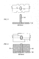
- FIG. 1 shows a cross-section of a magnetically actuated system in accordance with various embodiments of the present invention.
- Magnetically actuated system 100 includes magnetic field (B-field) apparatus 160, magnetically actuated device 110, upper field focusing plate(s) 152, and lower field focusing plate(s) 154.
- Magnetically actuated device 110 includes a conductive coil seen in cross-section at 112.
- the B-field apparatus 160 produces a magnetic field across conductive coil 112.
- the B-field is shown by arrows 120.
- B-field apparatus 160 includes multiple magnets having various orientations. These magnets work together to "focus" B-field 120 into an area of the conductive coil where the resulting force will have the greatest effect. In other embodiments, B-field apparatus 160 includes multiple magnets and a magnetically permeable core to aid in focusing the resulting B-field.
- Upper and lower field focusing plates 152, 154 include magnetically permeable materials.
- the magnetically permeable materials are positioned to further focus the B-field in areas of the conductive coil 112.
- the various embodiments of the present invention combine different permutations of magnets and magnetically permeable materials to focus the B-field in areas of the conductive coil where greater Lorentz forces are desired. These permutations are shown in, and described below with reference to, Figures 3-13 .
- Figure 2 shows a perspective view of a magnetically actuated device having a movable platform with a conductive coil.
- Device 110 includes movable platform 240 and mirror 216.
- movable platform 240 is a gimbaled structure coupled to the frame of device 110 by flexures 210 and 212, and mirror 216 is coupled to movable platform 240 by flexures 220 and 222.
- Movable platform 240 has a conductive coil 112 capable of carrying current.
- flexures 210 and/or 212 include conductors to carry current to and from conductive coil 112.
- Flexures 210 and 212 allow movable platform 240 to move in one angular dimension (also referred to as a "drive axis"). Likewise, flexures 220 and 222 allow mirror 216 to move on a second drive axis. In embodiments represented by Figure 2 , the two drive axes are 90 degrees apart, but this is not a limitation of the present invention.
- various B-field apparatuses impose and focus a magnetic field 120 on conductive coil 112.
- the magnetic field imposed on the conductive coil has a component in the plane of the coil, and is oriented at roughly 45° with respect to the two drive axes.
- the in-plane current in the coil windings interacts with the in-plane magnetic field to produce out-of-plane Lorentz forces on the conductors. Since the drive current forms a loop on movable platform 240, the current reverses sign across the drive axes. This means the Lorentz forces also reverse sign across the drive axes, resulting in a torque in the plane of and normal to the magnetic field. This combined torque produces responses in the two scan directions depending on the frequency content of the torque.
- one magnetic field is used to produce angular movement of the mirror on both drive axes.
- the B-field 120 has a component perpendicular to, and in the plane of, the conductive coil 112.
- required drive power can be reduced if the intensity of these in-plane perpendicular B-field vector components is increased.
- the drive torque is related to the product of the normal component of the magnetic B field and the coil drive current.
- a 10% increase in B field will allow a 10% decrease in current.
- the power required to drive the coil current is related to the square of the current, a 10% increase in B field will result in a 21% decrease in drive power.
- the various embodiments of the present invention are described relative to the magnetically actuated device shown in Figure 2 .
- the conductive coil is elliptical and on a gimballed movable platform with a mirror having drive axes at substantially 90 degrees to the drive axes of the movable platform.
- the various embodiments of the invention may be utilized with any magnetically actuated device and are not limited to the device as shown in Figure 2 .
- magnet assemblies and magnetically actuated systems described below can be utilized to provide a Lorentz force on any conductor having any shape on any movable platform.
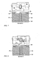
- FIG. 3 shows an exploded view of a magnetically actuated system with multiple field focusing plates.
- Magnetically actuated system 300 includes bottom plate 302, magnets 310 and 320, magnetically permeable core 330, lower field focusing plates 342 and 344, magnetically actuated device 110, upper field focusing plates 352 and 354, and die carrier 360.
- magnetically actuated device 110 When system 300 is assembled, magnetically actuated device 110 is nominally situated above magnets 310, 320 and lower field focusing plates 342, 344, and below upper field focusing plates 352, 354.
- the conductive coil on device 110 is said to be nominally in a "platform plane.” When the conductive coil is at rest, it is in the platform plane, and when it is moving, it may have an angular displacement relative to the platform plane.
- This terminology has been selected to refer to the plane in which the coil resides, and is not meant to imply any further structural limitations. Further, various embodiments are described using terms such as “above,” “below,” “up,” “down,” etc. These terms have been selected to allow the description of relative placement and orientation of components and are not meant to imply any absolute orientation.
- Magnets 310 and 320 are permanent magnets situated beneath the conductive coil on device 110, and have various magnetic orientations. For example, magnet 310 has a north pole facing down and a south pole facing up, and magnet 320 is oriented parallel to magnet 310 with a north pole facing up and a south pole facing down. Magnets 310 and 320 are shown oriented perpendicular to the platform plane.
- magnets 310 and 320 are oriented such that they produce a magnetic field that is misaligned with respect to the drive axes of device 110.
- the conductive coil on device 110 is elliptical in shape with the two drive axes on the major and minor ellipse axes.
- Magnets 310 and 320 are oriented such that the resulting magnetic field does not align with either of the drive axes.
- the generated B-field can be positioned to cross the conductive coil at a point in the ellipse where drive torque is needed. See B-field 120 in Figure 2 .
- Magnets 310 and 320 are shown generally having an "L" shape, but this is not a limitation of the present invention. In some embodiments, magnets 310 and 320 are triangular, and in other embodiments, magnets 310 and 320 are rectangular. Magnets 310 and 320 are shown mounted to base plate 302. In some embodiments, base plate 302 is made of a magnetically permeable material to aid in "closing" the magnetic circuit, although this is not a limitation of the present invention.
- Core 330 is made from a magnetically permeable material such as steel. Core 330 is positioned between magnets 310 and 320 beneath the conductive coil.
- the conductive coil on device 110 has an inner outline and an outer outline when viewed from above. In some embodiments, when viewed from above, core 330 is entirely within the inner outline of the conductive coil.
- Core 330 provides a lower reluctance path for the magnetic field, so the magnetic field passing through the conductive coil tends to enter and exit core 330 (and the inner outline of the coil) at closer to 90 degrees. This provides more drive torque for a given magnetic field strength.
- Die carrier 360 is used to house the various components shown in Figure 3 .
- device 110 may mechanically and/or electrically connect to die carrier 360.
- the various field focusing plates shown in Figure 3 may be held in place by die carrier 360.
- Die carrier 360 is shown with an aperture above the movable platform of device 110. This aperture allows light to enter and be reflected by the mirror.
- Figure 4 shows the same magnetically actuated system as Figure 3 , but without the die carrier 360.
- the different field focusing plates may have various shapes.
- the field focusing plates are placed outside the outer outline of the conductive coil.
- Field focusing plates 342, 344, 352, and 354 are made from a magnetically permeable material that provides a low reluctance path for the magnetic field. Through strategic shaping and placement of the field focusing plates, the magnetic field produced by magnets 310 and 320 can be "steered" to areas of the conductive coil where high magnetic field strength is desired.
- upper field focusing plates 352, 354 have stepped portions 353, 355.
- the stepped portions of the upper field focusing plates provide a low reluctance path for the magnetic field. This encourages the magnetic field to travel through the upper field focusing plates substantially parallel to the platform plane.
- the lower field focusing plates are substantially flat and are entirely beneath the platform plane. The combination of the stepped upper field focusing plates and the substantially flat lower field focusing plates encourage the magnetic field to travel substantially parallel to the conductive coil.
- the upper and lower field focusing plates are further shaped to provide a low reluctance path for the magnetic field near areas of the coil where high magnetic field strength is desired.
- the field focusing plates have various protruding legs to control the "spray" of magnetic field as it leaves the permeable material.
- lower field focusing plates 342, 344 include legs 343, 345.
- all of the field focusing plates include one or more protruding legs. The leg(s) help contain the spray out and size and shape changes in the leg(s) provide a level of control over the B-field that affects relative angles between the B-field and the conductive coil.
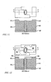
- Figures 5-8 show plan views and sectional views of the magnetically actuated system of Figures 3-4 .
- Figure 5 shows a plan view and sectional view of base plate 302 and magnetically permeable core 330.
- Figure 6 shows a plan view and sectional view of base plate 302, core 330, and magnets 310 and 320.
- Figure 7 shows a plan view and sectional view that includes upper field focusing plates 352 and 354.
- upper field focusing plates 352 and 354 are nominally positioned above the platform plane; however, the stepped portions 353 and 355 of the upper field focusing plates occupy some space in the platform plane, and extend to very near magnets 310 and 320.
- the low reluctance of the upper field focusing plates 352 and 354 helps steer the magnetic field from magnets 310 and 320 up through stepped portions 353 and 355 and through the horizontal portion of the plates above the platform plane.
- Upper field focusing plates 352 and 354 may have any shape. As shown in Figure 7 , in some embodiments, the stepped portions are at the outer extremes, and the horizontal portions extend to near the areas where the magnetic field is desired. Some embodiments vary the shape of the upper field focusing plates, and other embodiments vary the thickness of the upper field focusing plates. In some embodiments, more or less than two upper field focusing plates are included. For example, in some embodiments, one upper field focusing plate is included. Also for example, in some embodiments, three or more upper field focusing plates are included. Further, in some embodiments, upper field focusing plates 352 and 354 are omitted. These embodiments eliminate the volume and weight associated with the upper field focusing plates.
- Figure 8 shows a plan view and sectional view that includes lower field focusing plates 342 and 344.
- lower field focusing plates 342 and 344 are nominally positioned above magnets 310 and 320, and below the platform plane. The low reluctance of the lower field focusing plates 342 and 344 helps steer the magnetic field from magnets 310 and 320 horizontally through the magnetically permeable material.
- more or less than two lower field focusing plates are included.
- one lower field focusing plate is included.
- three or more lower field focusing plates are included.
- lower field focusing plates 342 and 344 are omitted. These embodiments eliminate the volume and weight associated with the lower field focusing plates.
- FIG. 9 shows an exploded view of a magnetically actuated system with multiple field focusing plates.
- Magnetically actuated system 900 includes bottom plate 302, magnets 910 and 920, magnetically permeable core 330, lower field focusing plates 342 and 344, magnetically actuated device 110, upper field focusing plates 952 and 954, and die carrier 360.
- magnetically actuated device 110 When system 900 is assembled, magnetically actuated device 110 is nominally situated above magnets 910, 920 and lower field focusing plates 342, 344, and below upper field focusing plates 952, 954.
- the conductive coil on device 110 is said to be nominally in a "platform plane.” When the conductive coil is at rest, it is in the platform plane, and when it is moving, it may have an angular displacement relative to the platform plane.
- This terminology has been selected to refer to the plane in which the coil resides, and is not meant to imply any further structural limitations. Further, various embodiments are described using terms such as “above,” “below,” “up,” “down,” etc. These terms have been selected to allow the description of relative placement and orientation of components and are not meant to imply any absolute orientation.
- Magnets 910, 920, and magnetically permeable core 330 form a B-field apparatus such as B-field apparatus 160 ( Figure 1 ).
- Magnets 910 and 920 are permanent magnets that have various magnetic orientations. For example, magnet 910 has a north pole facing down and a south pole facing up, and magnet 920 is oriented parallel to magnet 910 with a north pole facing up and a south pole facing down. Magnets 910 and 920 are shown oriented perpendicular to the platform plane.
- magnets 910 and 920 are oriented such that they produce a magnetic field that is misaligned with respect to the drive axes of device 110.
- the conductive coil on device 110 is elliptical in shape with the two drive axes on the major and minor ellipse axes.
- Magnets 910 and 920 are oriented such that the resulting magnetic field does not align with either of the drive axes.
- the generated B-field can be positioned to cross the conductive coil at a point in the ellipse where drive torque is needed. See B-field 120 in Figure 2 .
- Magnets 910 and 920 are shown generally having an "L" shape, but this is not a limitation of the present invention. In some embodiments, magnets 910 and 920 are triangular, and in other embodiments, magnets 910 and 920 are rectangular. Magnets 910 and 920 are shown mounted to base plate 302. In some embodiments, base plate 302 is made of a magnetically permeable material to aid in "closing" the magnetic circuit, although this is not a limitation of the present invention.
- Magnets 910 and 920 include stepped portions 912 and 922.
- the stepped portions form a recessed area within which the lower field focusing plates and device 110 reside.
- the stepped portions are shown as rectangular, however this is not a limitations of the present invention.
- the stepped portions of the magnets may be any shape and may be placed anywhere on magnets 910 and 920.
- Core 330 is made from a magnetically permeable material such as steel. Core 330 is positioned between magnets 910 and 920 beneath the conductive coil.
- the conductive coil on device 110 has an inner outline and an outer outline when viewed from above. In some embodiments, when viewed from above, core 330 is entirely within the inner outline of the conductive coil.
- Core 330 provides a lower reluctance path for the magnetic field, so the magnetic field passing through the conductive coil tends to enter and exit core 330 (and the inner outline of the coil) at closer to 90 degrees. This provides more drive torque for a given magnetic field strength.
- Die carrier 360 is used to house the various components shown in Figure 9 .
- device 110 may mechanically and/or electrically connect to die carrier 360.
- the various field focusing plates shown in Figure 9 may be held in place by die carrier 360.
- Die carrier 360 is shown with an aperture above the movable platform of device 110. This aperture allows light to enter and be reflected by the mirror.
- Figure 10 shows the same magnetically actuated system as Figure 9 , but without the die carrier 360.
- the different field focusing plates may have various shapes.
- the field focusing plates are placed outside the outer outline of the conductive coil.
- Field focusing plates 342, 344, 952, and 954 are made from a magnetically permeable material that provides a low reluctance path for the magnetic field. Through strategic shaping and placement of the field focusing plates, the magnetic field produced by magnets 910 and 920 can be "steered" to areas of the conductive coil where high magnetic field strength is desired.
- upper field focusing plates 952, 954 contact or very nearly contact the stepped portions of magnets 910 and 920.
- the upper field focusing plates provide a low reluctance path for the magnetic field. This encourages the magnetic field to travel through the upper field focusing plates substantially parallel to the platform plane.
- the lower field focusing plates are substantially flat and are entirely beneath the platform plane. The combination of the stepped magnets, the upper field focusing plates, and the lower field focusing plates encourages the magnetic field to travel substantially parallel to the conductive coil.
- the upper and lower field focusing plates are further shaped to provide a low reluctance path for the magnetic field near areas of the coil where high magnetic field strength is desired.
- Figures 11-13 show plan views and sectional views of the magnetically actuated system of Figures 9-10 .
- Figure 11 shows a plan view and sectional view of base plate 302, magnetically permeable core 330, and magnets 910 and 920.
- Figure 12 shows a plan view and sectional view that includes upper field focusing plates 952 and 954.
- magnets 910 and 920 are nominally positioned below the platform plane; however, the stepped portions 912 and 922 of magnets 910 and 920 occupy some space in the platform plane, and extend to very near the upper field focusing plates.
- the low reluctance of the upper field focusing plates 952 and 954 helps steer the magnetic field from magnets 910 and 920 from stepped portions 912 and 922 through the horizontal portion of the plates above the platform plane.
- Upper field focusing plates 952 and 954 may have any shape. As shown in Figure 12 , in some embodiments, the upper field focusing plates contact the stepped portions 912 and 922 at the outer extremes and extend to near the areas where the magnetic field is desired. Some embodiments vary the shape of the upper field focusing plates, and other embodiments vary the thickness of the upper field focusing plates. In some embodiments, more or less than two upper field focusing plates are included. For example, in some embodiments, one upper field focusing plate is included. Also for example, in some embodiments, three or more upper field focusing plates are included. Further, in some embodiments, upper field focusing plates 952 and 954 are omitted. These embodiments eliminate the volume and weight associated with the upper field focusing plates.
- Figure 13 shows a plan view and sectional view that includes lower field focusing plates 342 and 344.
- lower field focusing plates 342 and 344 are nominally positioned above magnets 910 and 920, and below the platform plane. The low reluctance of the lower field focusing plates 342 and 344 helps steer the magnetic field from magnets 910 and 920 horizontally through the magnetically permeable material.
- more or less than two lower field focusing plates are included.
- one lower field focusing plate is included.
- three or more lower field focusing plates are included.
- lower field focusing plates 342 and 344 are omitted. These embodiments eliminate the volume and weight associated with the lower field focusing plates.
- Figure 14 shows a color laser projection apparatus.
- System 1400 includes image processing component 1402, laser light sources 1410, 1420, and 1430.
- Projection system 1400 also includes mirrors 1403, 1405, and 1407, fold mirror 1450, magnetically actuated system 100, mirror 216, driver 1492, and digital control component 1490.
- image processing component 1402 receives video data on node 1401, receives a pixel clock from digital control component 1490, and produces commanded luminance values to drive the laser light sources when pixels are to be displayed.
- Image processing component 1402 may include any suitable hardware and/or software useful to produce color luminance values from video data.
- image processing component 1402 may include application specific integrated circuits (ASICs), one or more processors, or the like.
- ASICs application specific integrated circuits
- Laser light sources 1410, 1420, and 1430 receive commanded luminance values and produce light. Each light source produces a narrow beam of light which is directed to mirror 216 via guiding optics. For example, blue laser light source 1430 produces blue light which is reflected off mirror 1403 and is passed through mirrors 1405 and 1407; green laser light source 1420 produces green light which is reflected off mirror 1405 and is passed through mirror 1407; and red laser light source 1410 produces red light which is reflected off mirror 1407. At 1409, the red, green, and blue light are combined. The combined laser light is reflected off fold mirror 1450 on its way to mirror 216. After reflecting off mirror 216, the laser light bypasses fold mirror 1450 to sweep a raster pattern and create an image at 1480.
- blue laser light source 1430 produces blue light which is reflected off mirror 1403 and is passed through mirrors 1405 and 1407
- green laser light source 1420 produces green light which is reflected off mirror 1405 and is passed through mirror 1407
- red laser light source 1410 produces red
- mirror 216 rotates on two axes in response to electrical stimuli received on node 1493 from driver 1492.
- mirror 216 ( Figure 2 ) rotates on two axes in response to the interaction between current in conductive coil 112 and B-field 120.
- Magnetically actuated system 100 may be any of the embodiments described herein.
- system 100 may include any of the systems described with reference to Figures 3-13 .
- Projector 1400 is described as an example application, and the various embodiments of the invention are not so limited.
- the compact magnet assemblies described herein may be used with other mechanically actuated systems without departing from the scope of the present invention.
- FIG. 15 shows a block diagram of a mobile device in accordance with various embodiments of the present invention.
- mobile device 1500 includes wireless interface 1510, processor 1520, memory 1530, and scanning projector 1400.
- Scanning projector 1400 paints a raster image at 1480.
- Scanning projector 1400 is described with reference to Figure 14 .
- scanning projector 1400 includes a wavelength combining apparatus such as those shown in, and described with reference to, earlier figures.
- Scanning projector 1400 may receive image data from any image source: For example, in some embodiments, scanning projector 1400 includes memory that holds still images. In other embodiments, scanning projector 1400 includes memory that includes video images. In still further embodiments, scanning projector 1400 displays imagery received from external sources such as connectors, wireless interface 1510, or the like.
- Wireless interface 1510 may include any wireless transmission and/or reception capabilities.
- wireless interface 1510 includes a network interface card (NIC) capable of communicating over a wireless network.
- NIC network interface card
- wireless interface 1510 may include cellular telephone capabilities.
- wireless interface 1510 may include a global positioning system (GPS) receiver.
- GPS global positioning system
- Processor 1520 may be any type of processor capable of communicating with the various components in mobile device 1500.
- processor 1520 may be an embedded processor available from application specific integrated circuit (ASIC) vendors, or may be a commercially available microprocessor.
- ASIC application specific integrated circuit
- processor 1520 provides image or video data to scanning projector 1400.
- the image or video data may be retrieved from wireless interface 1510 or may be derived from data retrieved from wireless interface 1510.
- scanning projector 1400 may display images or video received directly from wireless interface 1510.
- processor 1520 may provide overlays to add to images and/or video received from wireless interface 1510, or may alter stored imagery based on data received from wireless interface 1510 (e.g., modifying a map display in GPS embodiments in which wireless interface 1510 provides location coordinates).
- Mobile device 1600 may be a hand held projection device with or without communications ability.
- mobile device 1600 may be a handheld projector with little or no other capabilities.
- mobile device 1600 may be a device usable for communications, including for example, a cellular phone, a smart phone, a personal digital assistant (PDA), a global positioning system (GPS) receiver, or the like.
- PDA personal digital assistant
- GPS global positioning system
- mobile device 1600 may be connected to a larger network via a wireless (e.g., WiMax) or cellular connection, or this device can accept data messages or video content via an unregulated spectrum (e.g., WiFi) connection.
- WiMax wireless
- WiFi unregulated spectrum
- Mobile device 1600 includes scanning projector 1400 to create an image with light at 1480.
- Mobile device 1600 also includes many other types of circuitry; however, they are intentionally omitted from Figure 16 for clarity.
- Mobile device 1600 includes display 1610, keypad 1620, audio port 1602, control buttons 1604, card slot 1606, and audio/video (A/V) port 1608. None of these elements are essential.
- mobile device 1600 may only include scanning projector 1400 without any of display 1610, keypad 1620, audio port 1602, control buttons 1604, card slot 1606, or A/V port 1608.
- Some embodiments include a subset of these elements.
- an accessory projector product may include scanning projector 1400, control buttons 1604 and A/V port 1608.
- Display 1610 may be any type of display.
- display 1610 includes a liquid crystal display (LCD) screen.
- LCD liquid crystal display
- Display 1610 may always display the same content projected at 1480 or different content.
- an accessory projector product may always display the same content, whereas a mobile phone embodiment may project one type of content at 1480 while display different content on display 1610.
- Keypad 1620 may be a phone keypad or any other type of keypad.
- A/V port 1608 accepts and/or transmits video and/or audio signals.
- A/V port 1608 may be a digital port that accepts a cable suitable to carry digital audio and video data.
- A/V port 1608 may include RCA jacks to accept composite inputs.
- A/V port 1608 may include a VGA connector to accept analog video signals.
- mobile device 1600 may be tethered to an external signal source through A/V port 1608, and mobile device 1600 may project content accepted through A/V port 1608.
- mobile device 1600 may be an originator of content, and A/V port 1608 is used to transmit content to a different device.
- Audio port 1602 provides audio signals.
- mobile device 1600 is a media player that can store and play audio and video.
- the video may be projected at 1480 and the audio may be output at audio port 1602.
- mobile device 1600 may be an accessory projector that receives audio and video at A/V port 1608.
- mobile device 1600 may project the video content at 1480, and output the audio content at audio port 1602.
- Mobile device 1600 also includes card slot 1606.
- a memory card inserted in card slot 1606 may provide a source for audio to be output at audio port 1602 and/or video data to be projected at 1480.
- Card slot 1606 may receive any type of solid state memory device, including for example, Multimedia Memory Cards (MMCs), Memory Stick DUOs, secure digital (SD) memory cards, and Smart Media cards.
- MMCs Multimedia Memory Cards
- SD secure digital
- Smart Media cards Smart Media cards.
- Figure 17 shows a head-up display system in accordance with various embodiments of the invention.
- Projector 1400 is shown mounted in a vehicle dash to project the head-up display at 1700.
- an automotive head-up display is shown in Figure 17 , this is not a limitation of the present invention.
- various embodiments of the invention include head-up displays in avionics application, air traffic control applications, and other applications.
- Figure 18 shows eyewear in accordance with various embodiments of the invention.
- Eyewear 1800 includes projector 1400 to project a display in the eyewear's field of view.
- eyewear 1800 is see-through and in other embodiments, eyewear 1800 is opaque.
- eyewear may be used in an augmented reality application in which a wearer can see the display from projector 1400 overlaid on the physical world.
- eyewear may be used in a virtual reality application, in which a wearer's entire view is generated by projector 1400.
- FIG 18 shows only one projector 1400 is shown in Figure 18 , this is not a limitation of the present invention.
- eyewear 1800 includes two projectors; one for each eye.
Description
- Magnetic actuation makes use of "Lorentz Forces" in which a force on a current-carrying conductor is related to the current in the conductor and the strength of a magnetic field across the conductor. The force exerted is perpendicular to the direction of the current in the conductor and perpendicular to the magnetic field.
- In magnetically actuated systems, power efficiency can be gained by using larger magnets to create a stronger magnetic field. The larger magnets, however, are heavier and increase volume requirements of the resulting system. On the other hand, volume and weight can be reduced by increasing the current in the conductor, but this is at the expense of increased power consumption. Accordingly, one can see that a trade-off exists between power consumption and weight/volume in magnetically actuated systems.
- It is desirable to reduce both power consumption and weight/volume in magnetically actuated systems.
-
US 2008/0054732 A1 discloses an electromagnetic micro actuator including a base frame, a first movable part, a second movable part, at least one pair of permanent magnets, a coil part, and a deformation suppression portion. The first movable part is rotatably connected to the base frame by a pair of first supporting parts. The second movable part, which includes a mirror, is rotatably connected to the first movable part by a pair of second supporting parts. The permanent magnets are disposed to face the first and second supporting parts, respectively. - The present invention is defined by the independent claims, taking due account of any element which is equivalent to an element specified in the claims. The dependent claims concern optional features of some embodiments of the invention.
-
-
Figure 1 shows a cross-section of a magnetically actuated system in accordance with various embodiments of the present invention; -
Figure 2 shows a perspective view of a magnetically actuated device having a movable platform with a conductive coil; -
Figures 3-4 show exploded views of a magnetically actuated system with multiple field focusing plates; -
Figures 5-8 show plan views and sectional views of the magnetically actuated system ofFigures 3-4 ; -
Figures 9-10 show exploded views of a magnetically actuated system with multiple field focusing plates; -
Figures 11-13 show plan views and sectional views of the magnetically actuated system ofFigures 9-10 ; -
Figure 14 shows a color laser projector; -
Figure 15 shows a block diagram of a mobile device in accordance with various embodiments of the present invention; -
Figure 16 shows a mobile device in accordance with various embodiments of the present invention; -
Figure 17 shows a head-up display system in accordance with various embodiments of the invention; and -
Figure 18 shows eyewear in accordance with various embodiments of the invention. - In the following detailed description, reference is made to the accompanying drawings that show, by way of illustration, specific embodiments in which the invention may be practiced. These embodiments are described in sufficient detail to enable those skilled in the art to practice the invention. It is to be understood that the various embodiments of the invention, although different, are not necessarily mutually exclusive. For example, a particular feature, structure, or characteristic described herein in connection with one embodiment may be implemented within other embodiments without departing from the scope of the invention. In addition, it is to be understood that the location or arrangement of individual elements within each disclosed embodiment may be modified without departing from the scope of the invention. The following detailed description is, therefore, not to be taken in a limiting sense, and the scope of the present invention is defined only by the appended claims, appropriately interpreted, along with the full range of equivalents to which the claims are entitled. In the drawings, like numerals refer to the same or similar functionality throughout the several views.
-
Figure 1 shows a cross-section of a magnetically actuated system in accordance with various embodiments of the present invention. Magnetically actuatedsystem 100 includes magnetic field (B-field)apparatus 160, magnetically actuateddevice 110, upper field focusing plate(s) 152, and lower field focusing plate(s) 154. Magnetically actuateddevice 110 includes a conductive coil seen in cross-section at 112. The B-field apparatus 160 produces a magnetic field acrossconductive coil 112. The B-field is shown byarrows 120. - In some embodiments, B-
field apparatus 160 includes multiple magnets having various orientations. These magnets work together to "focus" B-field 120 into an area of the conductive coil where the resulting force will have the greatest effect. In other embodiments, B-field apparatus 160 includes multiple magnets and a magnetically permeable core to aid in focusing the resulting B-field. - Upper and lower field focusing plates 152, 154 include magnetically permeable materials. The magnetically permeable materials are positioned to further focus the B-field in areas of the
conductive coil 112. The various embodiments of the present invention combine different permutations of magnets and magnetically permeable materials to focus the B-field in areas of the conductive coil where greater Lorentz forces are desired. These permutations are shown in, and described below with reference to,Figures 3-13 . -
Figure 2 shows a perspective view of a magnetically actuated device having a movable platform with a conductive coil.Device 110 includesmovable platform 240 andmirror 216. In embodiments represented byFigure 2 ,movable platform 240 is a gimbaled structure coupled to the frame ofdevice 110 byflexures mirror 216 is coupled tomovable platform 240 byflexures Movable platform 240 has aconductive coil 112 capable of carrying current. In some embodiments,flexures 210 and/or 212 include conductors to carry current to and fromconductive coil 112. -
Flexures movable platform 240 to move in one angular dimension (also referred to as a "drive axis"). Likewise,flexures mirror 216 to move on a second drive axis. In embodiments represented byFigure 2 , the two drive axes are 90 degrees apart, but this is not a limitation of the present invention. - In operation, various B-field apparatuses impose and focus a
magnetic field 120 onconductive coil 112. The magnetic field imposed on the conductive coil has a component in the plane of the coil, and is oriented at roughly 45° with respect to the two drive axes. The in-plane current in the coil windings interacts with the in-plane magnetic field to produce out-of-plane Lorentz forces on the conductors. Since the drive current forms a loop onmovable platform 240, the current reverses sign across the drive axes. This means the Lorentz forces also reverse sign across the drive axes, resulting in a torque in the plane of and normal to the magnetic field. This combined torque produces responses in the two scan directions depending on the frequency content of the torque. - In embodiments represented by
Figure 2 , one magnetic field is used to produce angular movement of the mirror on both drive axes. In order to cause movement ofplatform 240, the B-field 120 has a component perpendicular to, and in the plane of, theconductive coil 112. Furthermore, required drive power can be reduced if the intensity of these in-plane perpendicular B-field vector components is increased. The drive torque is related to the product of the normal component of the magnetic B field and the coil drive current. Thus, a 10% increase in B field will allow a 10% decrease in current. Because the power required to drive the coil current is related to the square of the current, a 10% increase in B field will result in a 21% decrease in drive power. - The various embodiments of the present invention are described relative to the magnetically actuated device shown in
Figure 2 . For example, as shown inFigure 2 , the conductive coil is elliptical and on a gimballed movable platform with a mirror having drive axes at substantially 90 degrees to the drive axes of the movable platform. The various embodiments of the invention may be utilized with any magnetically actuated device and are not limited to the device as shown inFigure 2 . For example, magnet assemblies and magnetically actuated systems described below can be utilized to provide a Lorentz force on any conductor having any shape on any movable platform. -
Figure 3 shows an exploded view of a magnetically actuated system with multiple field focusing plates. Magnetically actuated system 300 includesbottom plate 302,magnets permeable core 330, lowerfield focusing plates device 110, upperfield focusing plates carrier 360. - When system 300 is assembled, magnetically actuated
device 110 is nominally situated abovemagnets field focusing plates field focusing plates device 110 is said to be nominally in a "platform plane." When the conductive coil is at rest, it is in the platform plane, and when it is moving, it may have an angular displacement relative to the platform plane. This terminology has been selected to refer to the plane in which the coil resides, and is not meant to imply any further structural limitations. Further, various embodiments are described using terms such as "above," "below," "up," "down," etc. These terms have been selected to allow the description of relative placement and orientation of components and are not meant to imply any absolute orientation. -
Bottom plate 302,magnets permeable core 330 form a B-field apparatus such as B-field apparatus 160 (Figure 1 ).Magnets device 110, and have various magnetic orientations. For example,magnet 310 has a north pole facing down and a south pole facing up, andmagnet 320 is oriented parallel tomagnet 310 with a north pole facing up and a south pole facing down.Magnets - In some embodiments,
magnets device 110. For example, as shown inFigure 3 , the conductive coil ondevice 110 is elliptical in shape with the two drive axes on the major and minor ellipse axes.Magnets magnets field 120 inFigure 2 . -
Magnets magnets magnets Magnets base plate 302. In some embodiments,base plate 302 is made of a magnetically permeable material to aid in "closing" the magnetic circuit, although this is not a limitation of the present invention. -
Core 330 is made from a magnetically permeable material such as steel.Core 330 is positioned betweenmagnets device 110 has an inner outline and an outer outline when viewed from above. In some embodiments, when viewed from above,core 330 is entirely within the inner outline of the conductive coil. -
Core 330 provides a lower reluctance path for the magnetic field, so the magnetic field passing through the conductive coil tends to enter and exit core 330 (and the inner outline of the coil) at closer to 90 degrees. This provides more drive torque for a given magnetic field strength. -
Die carrier 360 is used to house the various components shown inFigure 3 . For example,device 110 may mechanically and/or electrically connect to diecarrier 360. Further, the various field focusing plates shown inFigure 3 may be held in place bydie carrier 360.Die carrier 360 is shown with an aperture above the movable platform ofdevice 110. This aperture allows light to enter and be reflected by the mirror. -
Figure 4 shows the same magnetically actuated system asFigure 3 , but without thedie carrier 360. As can be more clearly seen inFigure 4 , the different field focusing plates may have various shapes. In some embodiments, the field focusing plates are placed outside the outer outline of the conductive coil.Field focusing plates magnets - In embodiments represented by
Figure 4 , upperfield focusing plates portions Figure 4 , the lower field focusing plates are substantially flat and are entirely beneath the platform plane. The combination of the stepped upper field focusing plates and the substantially flat lower field focusing plates encourage the magnetic field to travel substantially parallel to the conductive coil. The upper and lower field focusing plates are further shaped to provide a low reluctance path for the magnetic field near areas of the coil where high magnetic field strength is desired. - One problem that exists in magnetics is even if you can get the field in the location you want it in, it is very difficult to control the "orientation" of the B-field because it wants to "spray" out of the permeable material. The field focusing plates have various protruding legs to control the "spray" of magnetic field as it leaves the permeable material. For example, lower
field focusing plates legs -
Figures 5-8 show plan views and sectional views of the magnetically actuated system ofFigures 3-4 .Figure 5 shows a plan view and sectional view ofbase plate 302 and magneticallypermeable core 330.Figure 6 shows a plan view and sectional view ofbase plate 302,core 330, andmagnets -
Figure 7 shows a plan view and sectional view that includes upperfield focusing plates Figure 7 , upperfield focusing plates portions magnets field focusing plates magnets portions - Upper
field focusing plates Figure 7 , in some embodiments, the stepped portions are at the outer extremes, and the horizontal portions extend to near the areas where the magnetic field is desired. Some embodiments vary the shape of the upper field focusing plates, and other embodiments vary the thickness of the upper field focusing plates. In some embodiments, more or less than two upper field focusing plates are included. For example, in some embodiments, one upper field focusing plate is included. Also for example, in some embodiments, three or more upper field focusing plates are included. Further, in some embodiments, upperfield focusing plates -
Figure 8 shows a plan view and sectional view that includes lowerfield focusing plates Figure 8 , lowerfield focusing plates magnets field focusing plates magnets field focusing plates -
Figure 9 shows an exploded view of a magnetically actuated system with multiple field focusing plates. Magnetically actuated system 900 includesbottom plate 302,magnets permeable core 330, lowerfield focusing plates device 110, upperfield focusing plates carrier 360. - When system 900 is assembled, magnetically actuated
device 110 is nominally situated abovemagnets field focusing plates field focusing plates device 110 is said to be nominally in a "platform plane." When the conductive coil is at rest, it is in the platform plane, and when it is moving, it may have an angular displacement relative to the platform plane. This terminology has been selected to refer to the plane in which the coil resides, and is not meant to imply any further structural limitations. Further, various embodiments are described using terms such as "above," "below," "up," "down," etc. These terms have been selected to allow the description of relative placement and orientation of components and are not meant to imply any absolute orientation. -
Bottom plate 302,magnets permeable core 330 form a B-field apparatus such as B-field apparatus 160 (Figure 1 ).Magnets magnet 910 has a north pole facing down and a south pole facing up, andmagnet 920 is oriented parallel tomagnet 910 with a north pole facing up and a south pole facing down.Magnets - In some embodiments,
magnets device 110. For example, as shown inFigure 9 , the conductive coil ondevice 110 is elliptical in shape with the two drive axes on the major and minor ellipse axes.Magnets magnets field 120 inFigure 2 . -
Magnets magnets magnets Magnets base plate 302. In some embodiments,base plate 302 is made of a magnetically permeable material to aid in "closing" the magnetic circuit, although this is not a limitation of the present invention. -
Magnets portions device 110 reside. The stepped portions are shown as rectangular, however this is not a limitations of the present invention. For example, the stepped portions of the magnets may be any shape and may be placed anywhere onmagnets -
Core 330 is made from a magnetically permeable material such as steel.Core 330 is positioned betweenmagnets device 110 has an inner outline and an outer outline when viewed from above. In some embodiments, when viewed from above,core 330 is entirely within the inner outline of the conductive coil. -
Core 330 provides a lower reluctance path for the magnetic field, so the magnetic field passing through the conductive coil tends to enter and exit core 330 (and the inner outline of the coil) at closer to 90 degrees. This provides more drive torque for a given magnetic field strength. -
Die carrier 360 is used to house the various components shown inFigure 9 . For example,device 110 may mechanically and/or electrically connect to diecarrier 360. Further, the various field focusing plates shown inFigure 9 may be held in place bydie carrier 360.Die carrier 360 is shown with an aperture above the movable platform ofdevice 110. This aperture allows light to enter and be reflected by the mirror. -
Figure 10 shows the same magnetically actuated system asFigure 9 , but without thedie carrier 360. As can be more clearly seen inFigure 10 , the different field focusing plates may have various shapes. In some embodiments, the field focusing plates are placed outside the outer outline of the conductive coil.Field focusing plates magnets - In embodiments represented by
Figure 10 , upperfield focusing plates magnets Figure 10 , the lower field focusing plates are substantially flat and are entirely beneath the platform plane. The combination of the stepped magnets, the upper field focusing plates, and the lower field focusing plates encourages the magnetic field to travel substantially parallel to the conductive coil. The upper and lower field focusing plates are further shaped to provide a low reluctance path for the magnetic field near areas of the coil where high magnetic field strength is desired. -
Figures 11-13 show plan views and sectional views of the magnetically actuated system ofFigures 9-10 .Figure 11 shows a plan view and sectional view ofbase plate 302, magneticallypermeable core 330, andmagnets -
Figure 12 shows a plan view and sectional view that includes upperfield focusing plates Figure 12 ,magnets portions magnets field focusing plates magnets portions - Upper
field focusing plates Figure 12 , in some embodiments, the upper field focusing plates contact the steppedportions field focusing plates -
Figure 13 shows a plan view and sectional view that includes lowerfield focusing plates Figure 13 , lowerfield focusing plates magnets field focusing plates magnets field focusing plates -
Figure 14 shows a color laser projection apparatus.System 1400 includesimage processing component 1402,laser light sources Projection system 1400 also includesmirrors fold mirror 1450, magnetically actuatedsystem 100,mirror 216,driver 1492, anddigital control component 1490. - In operation,
image processing component 1402 receives video data onnode 1401, receives a pixel clock fromdigital control component 1490, and produces commanded luminance values to drive the laser light sources when pixels are to be displayed.Image processing component 1402 may include any suitable hardware and/or software useful to produce color luminance values from video data. For example,image processing component 1402 may include application specific integrated circuits (ASICs), one or more processors, or the like. -
Laser light sources laser light source 1430 produces blue light which is reflected offmirror 1403 and is passed throughmirrors laser light source 1420 produces green light which is reflected offmirror 1405 and is passed throughmirror 1407; and redlaser light source 1410 produces red light which is reflected offmirror 1407. At 1409, the red, green, and blue light are combined. The combined laser light is reflected offfold mirror 1450 on its way to mirror 216. After reflecting offmirror 216, the laser light bypassesfold mirror 1450 to sweep a raster pattern and create an image at 1480. - In some embodiments,
mirror 216 rotates on two axes in response to electrical stimuli received onnode 1493 fromdriver 1492. For example, mirror 216 (Figure 2 ) rotates on two axes in response to the interaction between current inconductive coil 112 and B-field 120. - Magnetically actuated
system 100 may be any of the embodiments described herein. For example,system 100 may include any of the systems described with reference toFigures 3-13 .Projector 1400 is described as an example application, and the various embodiments of the invention are not so limited. For example, the compact magnet assemblies described herein may be used with other mechanically actuated systems without departing from the scope of the present invention. -
Figure 15 shows a block diagram of a mobile device in accordance with various embodiments of the present invention. As shown inFigure 15 ,mobile device 1500 includeswireless interface 1510,processor 1520,memory 1530, andscanning projector 1400.Scanning projector 1400 paints a raster image at 1480.Scanning projector 1400 is described with reference toFigure 14 . In some embodiments,scanning projector 1400 includes a wavelength combining apparatus such as those shown in, and described with reference to, earlier figures. -
Scanning projector 1400 may receive image data from any image source: For example, in some embodiments,scanning projector 1400 includes memory that holds still images. In other embodiments,scanning projector 1400 includes memory that includes video images. In still further embodiments,scanning projector 1400 displays imagery received from external sources such as connectors,wireless interface 1510, or the like. -
Wireless interface 1510 may include any wireless transmission and/or reception capabilities. For example, in some embodiments,wireless interface 1510 includes a network interface card (NIC) capable of communicating over a wireless network. Also for example, in some embodiments,wireless interface 1510 may include cellular telephone capabilities. In still further embodiments,wireless interface 1510 may include a global positioning system (GPS) receiver. One skilled in the art will understand thatwireless interface 1510 may include any type of wireless communications capability without departing from the scope of the present invention. -
Processor 1520 may be any type of processor capable of communicating with the various components inmobile device 1500. For example,processor 1520 may be an embedded processor available from application specific integrated circuit (ASIC) vendors, or may be a commercially available microprocessor. In Some embodiments,processor 1520 provides image or video data toscanning projector 1400. The image or video data may be retrieved fromwireless interface 1510 or may be derived from data retrieved fromwireless interface 1510. For example, throughprocessor 1520,scanning projector 1400 may display images or video received directly fromwireless interface 1510. Also for example,processor 1520 may provide overlays to add to images and/or video received fromwireless interface 1510, or may alter stored imagery based on data received from wireless interface 1510 (e.g., modifying a map display in GPS embodiments in whichwireless interface 1510 provides location coordinates). -
Figure 16 shows a mobile device in accordance with various embodiments of the present invention.Mobile device 1600 may be a hand held projection device with or without communications ability. For example, in some embodiments,mobile device 1600 may be a handheld projector with little or no other capabilities. Also for example, in some embodiments,mobile device 1600 may be a device usable for communications, including for example, a cellular phone, a smart phone, a personal digital assistant (PDA), a global positioning system (GPS) receiver, or the like. Further,mobile device 1600 may be connected to a larger network via a wireless (e.g., WiMax) or cellular connection, or this device can accept data messages or video content via an unregulated spectrum (e.g., WiFi) connection. -
Mobile device 1600 includesscanning projector 1400 to create an image with light at 1480.Mobile device 1600 also includes many other types of circuitry; however, they are intentionally omitted fromFigure 16 for clarity. -
Mobile device 1600 includesdisplay 1610,keypad 1620,audio port 1602,control buttons 1604,card slot 1606, and audio/video (A/V)port 1608. None of these elements are essential. For example,mobile device 1600 may only includescanning projector 1400 without any ofdisplay 1610,keypad 1620,audio port 1602,control buttons 1604,card slot 1606, or A/V port 1608. Some embodiments include a subset of these elements. For example, an accessory projector product may includescanning projector 1400,control buttons 1604 and A/V port 1608. -
Display 1610 may be any type of display. For example, in some embodiments,display 1610 includes a liquid crystal display (LCD) screen.Display 1610 may always display the same content projected at 1480 or different content. For example, an accessory projector product may always display the same content, whereas a mobile phone embodiment may project one type of content at 1480 while display different content ondisplay 1610.Keypad 1620 may be a phone keypad or any other type of keypad. - A/
V port 1608 accepts and/or transmits video and/or audio signals. For example, A/V port 1608 may be a digital port that accepts a cable suitable to carry digital audio and video data. Further, A/V port 1608 may include RCA jacks to accept composite inputs. Still further, A/V port 1608 may include a VGA connector to accept analog video signals. In some embodiments,mobile device 1600 may be tethered to an external signal source through A/V port 1608, andmobile device 1600 may project content accepted through A/V port 1608. In other embodiments,mobile device 1600 may be an originator of content, and A/V port 1608 is used to transmit content to a different device. -
Audio port 1602 provides audio signals. For example, in some embodiments,mobile device 1600 is a media player that can store and play audio and video. In these embodiments, the video may be projected at 1480 and the audio may be output ataudio port 1602. In other embodiments,mobile device 1600 may be an accessory projector that receives audio and video at A/V port 1608. In these embodiments,mobile device 1600 may project the video content at 1480, and output the audio content ataudio port 1602. -
Mobile device 1600 also includescard slot 1606. In some embodiments, a memory card inserted incard slot 1606 may provide a source for audio to be output ataudio port 1602 and/or video data to be projected at 1480.Card slot 1606 may receive any type of solid state memory device, including for example, Multimedia Memory Cards (MMCs), Memory Stick DUOs, secure digital (SD) memory cards, and Smart Media cards. The foregoing list is meant to be exemplary, and not exhaustive. -
Figure 17 shows a head-up display system in accordance with various embodiments of the invention.Projector 1400 is shown mounted in a vehicle dash to project the head-up display at 1700. Although an automotive head-up display is shown inFigure 17 , this is not a limitation of the present invention. For example, various embodiments of the invention include head-up displays in avionics application, air traffic control applications, and other applications. -
Figure 18 shows eyewear in accordance with various embodiments of the invention.Eyewear 1800 includesprojector 1400 to project a display in the eyewear's field of view. In some embodiments,eyewear 1800 is see-through and in other embodiments,eyewear 1800 is opaque. For example, eyewear may be used in an augmented reality application in which a wearer can see the display fromprojector 1400 overlaid on the physical world. Also for example, eyewear may be used in a virtual reality application, in which a wearer's entire view is generated byprojector 1400. Although only oneprojector 1400 is shown inFigure 18 , this is not a limitation of the present invention. For example, in some embodiments,eyewear 1800 includes two projectors; one for each eye. - Although the present invention has been described in conjunction with certain embodiments, it is to be understood that modifications and variations may be resorted to without departing from the scope of the invention as those skilled in the art readily understand. Such modifications and variations are considered to be within the scope of the invention and the appended claims.
Claims (15)
- An apparatus comprising:at least one magnet (320, 310); anda movable platform (240) having a conductive coil (112);characterized in thatthe conductive coil (112) is nominally oriented in a platform plane above the at least one magnet (320, 310); andthe apparatus further comprises at least one upper field focusing plate (352, 354) of magnetically permeable material at least partially above the platform plane, wherein the at least one upper field focusing plate (352, 354) includes a stepped portion (353, 355) that at least partially occupies space in the platform plane.
- The apparatus of claim 1, wherein the at least one magnet (320, 310) comprises:a first magnet (320) oriented with a south pole facing down and a north pole facing up; anda second magnet (310) oriented parallel to the first magnet (320), the second magnet (310) having a north pole facing down and a south pole facing up.
- The apparatus of claim 1 or claim 2, further comprising at least one lower field focusing plate (342, 344) of magnetically permeable material between the magnet (310, 320) and the platform plane.
- The apparatus of claim 1 or claim 2 or claim 3, wherein the movable platform (240) includes a gimballed structure allowing the movable platform (240) to rotate out of the platform plane on a first axis, the movable platform (240) further including a reflective part (216) that can rotate relative to the gimballed structure on a second axis substantially 90 degrees from the first axis.
- An apparatus comprising:a first magnet (920);a second magnet (910); anda movable platform (240) having a conductive coil (112);characterized in thatthe first magnet (920) is oriented with a south pole facing down and a north pole facing up, the first magnet (920) having a first stepped portion (922) facing up;the second magnet (910) is oriented parallel to the first magnet (920), the second magnet (910) having a north pole facing down and a south pole facing up, the second magnet (910) having a second stepped portion (912) facing up, the first and second stepped portions (912, 922) forming a recessed area;the conductive coil (112) is nominally oriented in a platform plane above the first and second magnets (920, 910) and within the recessed area; andthe apparatus further comprises at least one lower field focusing plate (342, 344) of magnetically permeable material positioned in the recessed area beneath the platform plane to focus a resulting magnetic field in the platform plane.
- The apparatus of claim 5, further comprising at least one upper field focusing plate (952, 954) of magnetically permeable material positioned above the platform plane.
- The apparatus of claim 3 or claim 5, wherein the at least one lower field focusing plate (342, 344) includes at least one protruding leg (343, 345) to affect a relative angle between a magnetic field and the conductive coil (112).
- The apparatus of claim 3 or claim 6, wherein the at least one lower field focusing plate (342, 344) and the at least one upper field focusing plate (352, 354, 952, 954) each include at least one protruding leg (343, 345) to affect a relative angle between a magnetic field and the conductive coil (112).
- The apparatus of claim 5 or claim 6, wherein the conductive coil (112) has an outer outline and the at least one lower field focusing plate (342, 344) is shaped to be outside the outer outline of the conductive coil (112).
- The apparatus of claim 2 or claim 3 or claim 9, further comprising a magnetically permeable core (330) positioned between the first and second magnets (320, 310, 920, 910) and beneath the movable platform (240).
- The apparatus of claim 10 wherein the conductive coil (112) has an inner outline and the magnetically permeable core (330) is oriented beneath, and within the inner outline of, the conductive coil (112).
- The apparatus of claim 11, wherein the conductive coil (112) is elliptical.
- A method comprising:using a light source to produce light;using a mirror (216) to reflect the light, the mirror (216) mounted on a movable platform (240) in a platform plane, the movable platform (240) including a conductive coil (112); andusing at least one magnet (920, 910) to produce a magnetic field;characterized in thatat least one lower field focusing plate (342, 344) of magnetically permeable material is positioned beneath the platform plane;at least one upper field focusing plate (952, 954) of magnetically permeable material is positioned at least partially above the platform plane; andthe at least one magnet (920, 910) includes stepped portions (922, 912) that protrude from the at least one magnet (920, 910) and at least partially occupy space in the platform plane.
- The method of claim 13, wherein the at least one lower field focusing plate (342, 344) comprises two lower field focusing plates (342, 344).
- A method comprising:using a light source to produce light;using a mirror (216) to reflect the light, the mirror (216) mounted on a movable platform (240) in a platform plane, the movable platform (240) including a conductive coil (112); andusing at least one magnet (320, 310) to produce a magnetic field;characterized in thatat least one lower field focusing plate (342, 344) of magnetically permeable material is positioned beneath the platform plane;at least one upper field focusing plate (352, 354) of magnetically permeable material is positioned at least partially above the platform plane; andthe at least one upper field focusing plate (352, 354) comprises two upper field focusing plates (352, 354) that include stepped portions (353, 355) that protrude toward the at least one magnet (320, 310).
Applications Claiming Priority (2)
| Application Number | Priority Date | Filing Date | Title |
|---|---|---|---|
| US12/710,474 US8305672B2 (en) | 2010-02-23 | 2010-02-23 | Magnetically actuated system |
| PCT/US2011/023473 WO2011106134A2 (en) | 2010-02-23 | 2011-02-02 | Magnetically actuated system |
Publications (3)
| Publication Number | Publication Date |
|---|---|
| EP2539907A2 EP2539907A2 (en) | 2013-01-02 |
| EP2539907A4 EP2539907A4 (en) | 2013-08-14 |
| EP2539907B1 true EP2539907B1 (en) | 2015-08-12 |
Family
ID=44476280
Family Applications (1)
| Application Number | Title | Priority Date | Filing Date |
|---|---|---|---|
| EP11747843.8A Active EP2539907B1 (en) | 2010-02-23 | 2011-02-02 | Magnetically actuated system |
Country Status (6)
| Country | Link |
|---|---|
| US (1) | US8305672B2 (en) |
| EP (1) | EP2539907B1 (en) |
| JP (1) | JP5715651B2 (en) |
| KR (1) | KR101800611B1 (en) |
| CN (1) | CN102763176B (en) |
| WO (1) | WO2011106134A2 (en) |
Families Citing this family (8)
| Publication number | Priority date | Publication date | Assignee | Title |
|---|---|---|---|---|
| US20100141366A1 (en) * | 2008-12-04 | 2010-06-10 | Microvision, Inc. | Magnetically Actuated System |
| JPWO2015092907A1 (en) * | 2013-12-19 | 2017-03-16 | パイオニア株式会社 | Drive device |
| US10281715B2 (en) | 2015-06-16 | 2019-05-07 | Young Optics Inc. | Imaging displacement module |
| US10286607B1 (en) | 2017-12-19 | 2019-05-14 | Microvision, Inc. | Plastic laser welding with partial masking |
| US10591719B2 (en) | 2017-12-19 | 2020-03-17 | Microvision, Inc. | Laser welded scanner assemblies |
| TWI698696B (en) | 2018-05-11 | 2020-07-11 | 揚明光學股份有限公司 | Light path adjustment mechanism and fabrication method thereof |
| CN111694152B (en) * | 2019-03-15 | 2021-09-14 | 华为技术有限公司 | Head-mounted display and virtual reality system |
| CN111614226A (en) * | 2020-06-24 | 2020-09-01 | 雅科贝思精密机电(南通)有限公司 | Voice coil motor of variable-rigidity magnetic gravity compensator |
Family Cites Families (10)
| Publication number | Priority date | Publication date | Assignee | Title |
|---|---|---|---|---|
| JPS61260430A (en) * | 1985-05-15 | 1986-11-18 | Hitachi Ltd | Objective lens driving device |
| JP2722314B2 (en) * | 1993-12-20 | 1998-03-04 | 日本信号株式会社 | Planar type galvanometer mirror and method of manufacturing the same |
| US5898652A (en) | 1994-07-08 | 1999-04-27 | Seiko Epson Corporation | Support structure for an optical pickup |
| US7482730B2 (en) * | 2004-02-09 | 2009-01-27 | Microvision, Inc. | High performance MEMS scanner |
| US7265887B2 (en) * | 2005-03-02 | 2007-09-04 | Texas Instruments Incorporated | Two axis low inertia torsional hinged optical device |
| JP4247254B2 (en) | 2006-08-08 | 2009-04-02 | マイクロプレシジョン株式会社 | Electromagnetic drive type optical deflection element |
| KR100829563B1 (en) | 2006-09-01 | 2008-05-14 | 삼성전자주식회사 | Electromagnetic type micro actuator and Method for manufacturing the same |
| JP4928301B2 (en) * | 2007-02-20 | 2012-05-09 | キヤノン株式会社 | Oscillator device, driving method thereof, optical deflector, and image display device using optical deflector |
| JP5220382B2 (en) | 2007-10-24 | 2013-06-26 | ペンタックスリコーイメージング株式会社 | Electromagnetic actuator |
| DE102008042346A1 (en) * | 2008-09-25 | 2010-04-01 | Robert Bosch Gmbh | Magnetic yoke, micromechanical component and manufacturing method for a magnetic yoke and a micromechanical component |
-
2010
- 2010-02-23 US US12/710,474 patent/US8305672B2/en active Active
-
2011
- 2011-02-02 EP EP11747843.8A patent/EP2539907B1/en active Active
- 2011-02-02 KR KR1020127024388A patent/KR101800611B1/en active IP Right Grant
- 2011-02-02 JP JP2012555015A patent/JP5715651B2/en active Active
- 2011-02-02 CN CN201180010735.7A patent/CN102763176B/en active Active
- 2011-02-02 WO PCT/US2011/023473 patent/WO2011106134A2/en active Application Filing
Also Published As
| Publication number | Publication date |
|---|---|
| CN102763176B (en) | 2014-08-20 |
| US20110205612A1 (en) | 2011-08-25 |
| CN102763176A (en) | 2012-10-31 |
| JP5715651B2 (en) | 2015-05-13 |
| WO2011106134A3 (en) | 2011-11-24 |
| KR101800611B1 (en) | 2017-12-20 |
| KR20130027466A (en) | 2013-03-15 |
| US8305672B2 (en) | 2012-11-06 |
| WO2011106134A2 (en) | 2011-09-01 |
| EP2539907A4 (en) | 2013-08-14 |
| JP2013520837A (en) | 2013-06-06 |
| EP2539907A2 (en) | 2013-01-02 |
Similar Documents
| Publication | Publication Date | Title |
|---|---|---|
| EP2539907B1 (en) | Magnetically actuated system | |
| US8466762B2 (en) | Magnetically actuated system | |
| US8511838B2 (en) | Scanning laser projector with safety system | |
| US9693029B1 (en) | System and method for feedback control in scanning projectors | |
| US9223129B2 (en) | MEMS device with multi-segment flexures | |
| CN103901619A (en) | Head-mounted display | |
| US20120069415A1 (en) | Scanning Projector with Dynamic Scan Angle | |
| US20140313558A1 (en) | MEMS Device with Asymmetric Flexures | |
| US10001656B2 (en) | Devices and methods for speckle reduction in scanning projectors | |
| JP6904592B2 (en) | Multi-striped laser for laser-based projector displays | |
| US10108022B2 (en) | Devices and methods for speckle reduction in scanning projectors | |
| US20170293155A1 (en) | Devices and Methods for Speckle Reduction in Scanning Projectors Using Birefringence | |
| JP2009086139A (en) | Camera module and portable terminal | |
| US9798149B1 (en) | Devices and methods for optical power sensing scanning laser projectors | |
| JP5991001B2 (en) | Optical device, optical scanner, and image display device | |
| JP2014048615A (en) | Actuator, optical scanner, picture display unit and head-mounted display | |
| US10598943B2 (en) | Method and apparatus for collimating light from a laser diode | |
| US20180088329A1 (en) | Optical scanner, image display device, head-mounted display, and heads-up display | |
| JP2001108920A (en) | Color display device | |
| JP2016139018A (en) | Optical scanner, method for manufacturing optical scanner, image display device, and head-mounted display |
Legal Events
| Date | Code | Title | Description |
|---|---|---|---|
| PUAI | Public reference made under article 153(3) epc to a published international application that has entered the european phase |
Free format text: ORIGINAL CODE: 0009012 |
|
| 17P | Request for examination filed |
Effective date: 20120920 |
|
| AK | Designated contracting states |
Kind code of ref document: A2 Designated state(s): AL AT BE BG CH CY CZ DE DK EE ES FI FR GB GR HR HU IE IS IT LI LT LU LV MC MK MT NL NO PL PT RO RS SE SI SK SM TR |
|
| DAX | Request for extension of the european patent (deleted) | ||
| A4 | Supplementary search report drawn up and despatched |
Effective date: 20130717 |
|
| RIC1 | Information provided on ipc code assigned before grant |
Ipc: H01F 7/06 20060101AFI20130711BHEP Ipc: H02K 33/00 20060101ALI20130711BHEP |
|
| RAP1 | Party data changed (applicant data changed or rights of an application transferred) |
Owner name: MICROVISION, INC. |
|
| GRAP | Despatch of communication of intention to grant a patent |
Free format text: ORIGINAL CODE: EPIDOSNIGR1 |
|
| INTG | Intention to grant announced |
Effective date: 20150116 |
|
| GRAP | Despatch of communication of intention to grant a patent |
Free format text: ORIGINAL CODE: EPIDOSNIGR1 |
|
| GRAS | Grant fee paid |
Free format text: ORIGINAL CODE: EPIDOSNIGR3 |
|
| INTG | Intention to grant announced |
Effective date: 20150608 |
|
| GRAA | (expected) grant |
Free format text: ORIGINAL CODE: 0009210 |
|
| AK | Designated contracting states |
Kind code of ref document: B1 Designated state(s): AL AT BE BG CH CY CZ DE DK EE ES FI FR GB GR HR HU IE IS IT LI LT LU LV MC MK MT NL NO PL PT RO RS SE SI SK SM TR |
|
| REG | Reference to a national code |
Ref country code: GB Ref legal event code: FG4D |
|
| REG | Reference to a national code |
Ref country code: CH Ref legal event code: EP |
|
| REG | Reference to a national code |
Ref country code: AT Ref legal event code: REF Ref document number: 742778 Country of ref document: AT Kind code of ref document: T Effective date: 20150815 |
|
| REG | Reference to a national code |
Ref country code: IE Ref legal event code: FG4D |
|
| REG | Reference to a national code |
Ref country code: DE Ref legal event code: R096 Ref document number: 602011018722 Country of ref document: DE |
|
| REG | Reference to a national code |
Ref country code: FR Ref legal event code: PLFP Year of fee payment: 6 |
|
| REG | Reference to a national code |
Ref country code: LT Ref legal event code: MG4D |
|
| REG | Reference to a national code |
Ref country code: AT Ref legal event code: MK05 Ref document number: 742778 Country of ref document: AT Kind code of ref document: T Effective date: 20150812 |
|
| REG | Reference to a national code |
Ref country code: NL Ref legal event code: MP Effective date: 20150812 |
|
| PG25 | Lapsed in a contracting state [announced via postgrant information from national office to epo] |
Ref country code: GR Free format text: LAPSE BECAUSE OF FAILURE TO SUBMIT A TRANSLATION OF THE DESCRIPTION OR TO PAY THE FEE WITHIN THE PRESCRIBED TIME-LIMIT Effective date: 20151113 Ref country code: NO Free format text: LAPSE BECAUSE OF FAILURE TO SUBMIT A TRANSLATION OF THE DESCRIPTION OR TO PAY THE FEE WITHIN THE PRESCRIBED TIME-LIMIT Effective date: 20151112 Ref country code: LV Free format text: LAPSE BECAUSE OF FAILURE TO SUBMIT A TRANSLATION OF THE DESCRIPTION OR TO PAY THE FEE WITHIN THE PRESCRIBED TIME-LIMIT Effective date: 20150812 Ref country code: LT Free format text: LAPSE BECAUSE OF FAILURE TO SUBMIT A TRANSLATION OF THE DESCRIPTION OR TO PAY THE FEE WITHIN THE PRESCRIBED TIME-LIMIT Effective date: 20150812 Ref country code: FI Free format text: LAPSE BECAUSE OF FAILURE TO SUBMIT A TRANSLATION OF THE DESCRIPTION OR TO PAY THE FEE WITHIN THE PRESCRIBED TIME-LIMIT Effective date: 20150812 |
|
| PG25 | Lapsed in a contracting state [announced via postgrant information from national office to epo] |
Ref country code: AT Free format text: LAPSE BECAUSE OF FAILURE TO SUBMIT A TRANSLATION OF THE DESCRIPTION OR TO PAY THE FEE WITHIN THE PRESCRIBED TIME-LIMIT Effective date: 20150812 Ref country code: RS Free format text: LAPSE BECAUSE OF FAILURE TO SUBMIT A TRANSLATION OF THE DESCRIPTION OR TO PAY THE FEE WITHIN THE PRESCRIBED TIME-LIMIT Effective date: 20150812 Ref country code: IS Free format text: LAPSE BECAUSE OF FAILURE TO SUBMIT A TRANSLATION OF THE DESCRIPTION OR TO PAY THE FEE WITHIN THE PRESCRIBED TIME-LIMIT Effective date: 20151212 Ref country code: PT Free format text: LAPSE BECAUSE OF FAILURE TO SUBMIT A TRANSLATION OF THE DESCRIPTION OR TO PAY THE FEE WITHIN THE PRESCRIBED TIME-LIMIT Effective date: 20151214 Ref country code: HR Free format text: LAPSE BECAUSE OF FAILURE TO SUBMIT A TRANSLATION OF THE DESCRIPTION OR TO PAY THE FEE WITHIN THE PRESCRIBED TIME-LIMIT Effective date: 20150812 Ref country code: SE Free format text: LAPSE BECAUSE OF FAILURE TO SUBMIT A TRANSLATION OF THE DESCRIPTION OR TO PAY THE FEE WITHIN THE PRESCRIBED TIME-LIMIT Effective date: 20150812 Ref country code: ES Free format text: LAPSE BECAUSE OF FAILURE TO SUBMIT A TRANSLATION OF THE DESCRIPTION OR TO PAY THE FEE WITHIN THE PRESCRIBED TIME-LIMIT Effective date: 20150812 Ref country code: PL Free format text: LAPSE BECAUSE OF FAILURE TO SUBMIT A TRANSLATION OF THE DESCRIPTION OR TO PAY THE FEE WITHIN THE PRESCRIBED TIME-LIMIT Effective date: 20150812 |
|
| PG25 | Lapsed in a contracting state [announced via postgrant information from national office to epo] |
Ref country code: NL Free format text: LAPSE BECAUSE OF FAILURE TO SUBMIT A TRANSLATION OF THE DESCRIPTION OR TO PAY THE FEE WITHIN THE PRESCRIBED TIME-LIMIT Effective date: 20150812 |
|
| PG25 | Lapsed in a contracting state [announced via postgrant information from national office to epo] |
Ref country code: SK Free format text: LAPSE BECAUSE OF FAILURE TO SUBMIT A TRANSLATION OF THE DESCRIPTION OR TO PAY THE FEE WITHIN THE PRESCRIBED TIME-LIMIT Effective date: 20150812 Ref country code: EE Free format text: LAPSE BECAUSE OF FAILURE TO SUBMIT A TRANSLATION OF THE DESCRIPTION OR TO PAY THE FEE WITHIN THE PRESCRIBED TIME-LIMIT Effective date: 20150812 Ref country code: CZ Free format text: LAPSE BECAUSE OF FAILURE TO SUBMIT A TRANSLATION OF THE DESCRIPTION OR TO PAY THE FEE WITHIN THE PRESCRIBED TIME-LIMIT Effective date: 20150812 Ref country code: DK Free format text: LAPSE BECAUSE OF FAILURE TO SUBMIT A TRANSLATION OF THE DESCRIPTION OR TO PAY THE FEE WITHIN THE PRESCRIBED TIME-LIMIT Effective date: 20150812 Ref country code: IT Free format text: LAPSE BECAUSE OF FAILURE TO SUBMIT A TRANSLATION OF THE DESCRIPTION OR TO PAY THE FEE WITHIN THE PRESCRIBED TIME-LIMIT Effective date: 20150812 |
|
| REG | Reference to a national code |
Ref country code: DE Ref legal event code: R097 Ref document number: 602011018722 Country of ref document: DE |
|
| PG25 | Lapsed in a contracting state [announced via postgrant information from national office to epo] |
Ref country code: RO Free format text: LAPSE BECAUSE OF FAILURE TO SUBMIT A TRANSLATION OF THE DESCRIPTION OR TO PAY THE FEE WITHIN THE PRESCRIBED TIME-LIMIT Effective date: 20150812 Ref country code: BE Free format text: LAPSE BECAUSE OF NON-PAYMENT OF DUE FEES Effective date: 20160229 |
|
| PLBE | No opposition filed within time limit |
Free format text: ORIGINAL CODE: 0009261 |
|
| STAA | Information on the status of an ep patent application or granted ep patent |
Free format text: STATUS: NO OPPOSITION FILED WITHIN TIME LIMIT |
|
| 26N | No opposition filed |
Effective date: 20160513 |
|
| PG25 | Lapsed in a contracting state [announced via postgrant information from national office to epo] |
Ref country code: SI Free format text: LAPSE BECAUSE OF FAILURE TO SUBMIT A TRANSLATION OF THE DESCRIPTION OR TO PAY THE FEE WITHIN THE PRESCRIBED TIME-LIMIT Effective date: 20150812 |
|
| PG25 | Lapsed in a contracting state [announced via postgrant information from national office to epo] |
Ref country code: LU Free format text: LAPSE BECAUSE OF FAILURE TO SUBMIT A TRANSLATION OF THE DESCRIPTION OR TO PAY THE FEE WITHIN THE PRESCRIBED TIME-LIMIT Effective date: 20160202 Ref country code: MC Free format text: LAPSE BECAUSE OF FAILURE TO SUBMIT A TRANSLATION OF THE DESCRIPTION OR TO PAY THE FEE WITHIN THE PRESCRIBED TIME-LIMIT Effective date: 20150812 |
|
| REG | Reference to a national code |
Ref country code: CH Ref legal event code: PL |
|
| PG25 | Lapsed in a contracting state [announced via postgrant information from national office to epo] |
Ref country code: LI Free format text: LAPSE BECAUSE OF NON-PAYMENT OF DUE FEES Effective date: 20160229 Ref country code: CH Free format text: LAPSE BECAUSE OF NON-PAYMENT OF DUE FEES Effective date: 20160229 |
|
| REG | Reference to a national code |
Ref country code: IE Ref legal event code: MM4A |
|
| PG25 | Lapsed in a contracting state [announced via postgrant information from national office to epo] |
Ref country code: BE Free format text: LAPSE BECAUSE OF FAILURE TO SUBMIT A TRANSLATION OF THE DESCRIPTION OR TO PAY THE FEE WITHIN THE PRESCRIBED TIME-LIMIT Effective date: 20150812 |
|
| REG | Reference to a national code |
Ref country code: FR Ref legal event code: PLFP Year of fee payment: 7 |
|
| PG25 | Lapsed in a contracting state [announced via postgrant information from national office to epo] |
Ref country code: IE Free format text: LAPSE BECAUSE OF NON-PAYMENT OF DUE FEES Effective date: 20160202 |
|
| PG25 | Lapsed in a contracting state [announced via postgrant information from national office to epo] |
Ref country code: MT Free format text: LAPSE BECAUSE OF FAILURE TO SUBMIT A TRANSLATION OF THE DESCRIPTION OR TO PAY THE FEE WITHIN THE PRESCRIBED TIME-LIMIT Effective date: 20150812 |
|
| REG | Reference to a national code |
Ref country code: FR Ref legal event code: PLFP Year of fee payment: 8 |
|
| PG25 | Lapsed in a contracting state [announced via postgrant information from national office to epo] |
Ref country code: SM Free format text: LAPSE BECAUSE OF FAILURE TO SUBMIT A TRANSLATION OF THE DESCRIPTION OR TO PAY THE FEE WITHIN THE PRESCRIBED TIME-LIMIT Effective date: 20150812 Ref country code: CY Free format text: LAPSE BECAUSE OF FAILURE TO SUBMIT A TRANSLATION OF THE DESCRIPTION OR TO PAY THE FEE WITHIN THE PRESCRIBED TIME-LIMIT Effective date: 20150812 Ref country code: HU Free format text: LAPSE BECAUSE OF FAILURE TO SUBMIT A TRANSLATION OF THE DESCRIPTION OR TO PAY THE FEE WITHIN THE PRESCRIBED TIME-LIMIT; INVALID AB INITIO Effective date: 20110202 |
|
| PG25 | Lapsed in a contracting state [announced via postgrant information from national office to epo] |
Ref country code: TR Free format text: LAPSE BECAUSE OF FAILURE TO SUBMIT A TRANSLATION OF THE DESCRIPTION OR TO PAY THE FEE WITHIN THE PRESCRIBED TIME-LIMIT Effective date: 20150812 Ref country code: MT Free format text: LAPSE BECAUSE OF FAILURE TO SUBMIT A TRANSLATION OF THE DESCRIPTION OR TO PAY THE FEE WITHIN THE PRESCRIBED TIME-LIMIT Effective date: 20160229 Ref country code: MK Free format text: LAPSE BECAUSE OF FAILURE TO SUBMIT A TRANSLATION OF THE DESCRIPTION OR TO PAY THE FEE WITHIN THE PRESCRIBED TIME-LIMIT Effective date: 20150812 |
|
| PG25 | Lapsed in a contracting state [announced via postgrant information from national office to epo] |
Ref country code: BG Free format text: LAPSE BECAUSE OF FAILURE TO SUBMIT A TRANSLATION OF THE DESCRIPTION OR TO PAY THE FEE WITHIN THE PRESCRIBED TIME-LIMIT Effective date: 20150812 |
|
| PG25 | Lapsed in a contracting state [announced via postgrant information from national office to epo] |
Ref country code: AL Free format text: LAPSE BECAUSE OF FAILURE TO SUBMIT A TRANSLATION OF THE DESCRIPTION OR TO PAY THE FEE WITHIN THE PRESCRIBED TIME-LIMIT Effective date: 20150812 |
|
| PGFP | Annual fee paid to national office [announced via postgrant information from national office to epo] |
Ref country code: DE Payment date: 20221207 Year of fee payment: 13 |
|
| P01 | Opt-out of the competence of the unified patent court (upc) registered |
Effective date: 20230423 |
|
| PGFP | Annual fee paid to national office [announced via postgrant information from national office to epo] |
Ref country code: GB Payment date: 20231214 Year of fee payment: 14 |
|
| PGFP | Annual fee paid to national office [announced via postgrant information from national office to epo] |
Ref country code: FR Payment date: 20231212 Year of fee payment: 14 |