EP2539783B1 - Verfahren zur schwingungsgedämpften bewegung eines werkstücks - Google Patents
Verfahren zur schwingungsgedämpften bewegung eines werkstücks Download PDFInfo
- Publication number
- EP2539783B1 EP2539783B1 EP11711480.1A EP11711480A EP2539783B1 EP 2539783 B1 EP2539783 B1 EP 2539783B1 EP 11711480 A EP11711480 A EP 11711480A EP 2539783 B1 EP2539783 B1 EP 2539783B1
- Authority
- EP
- European Patent Office
- Prior art keywords
- function
- accordance
- phase
- workpiece
- acceleration
- Prior art date
- Legal status (The legal status is an assumption and is not a legal conclusion. Google has not performed a legal analysis and makes no representation as to the accuracy of the status listed.)
- Not-in-force
Links
Images



Classifications
-
- G—PHYSICS
- G05—CONTROLLING; REGULATING
- G05B—CONTROL OR REGULATING SYSTEMS IN GENERAL; FUNCTIONAL ELEMENTS OF SUCH SYSTEMS; MONITORING OR TESTING ARRANGEMENTS FOR SUCH SYSTEMS OR ELEMENTS
- G05B19/00—Program-control systems
- G05B19/02—Program-control systems electric
- G05B19/18—Numerical control [NC], i.e. automatically operating machines, in particular machine tools, e.g. in a manufacturing environment, so as to execute positioning, movement or co-ordinated operations by means of program data in numerical form
- G05B19/416—Numerical control [NC], i.e. automatically operating machines, in particular machine tools, e.g. in a manufacturing environment, so as to execute positioning, movement or co-ordinated operations by means of program data in numerical form characterised by control of velocity, acceleration or deceleration
-
- G—PHYSICS
- G05—CONTROLLING; REGULATING
- G05B—CONTROL OR REGULATING SYSTEMS IN GENERAL; FUNCTIONAL ELEMENTS OF SUCH SYSTEMS; MONITORING OR TESTING ARRANGEMENTS FOR SUCH SYSTEMS OR ELEMENTS
- G05B19/00—Program-control systems
- G05B19/02—Program-control systems electric
- G05B19/18—Numerical control [NC], i.e. automatically operating machines, in particular machine tools, e.g. in a manufacturing environment, so as to execute positioning, movement or co-ordinated operations by means of program data in numerical form
- G05B19/404—Numerical control [NC], i.e. automatically operating machines, in particular machine tools, e.g. in a manufacturing environment, so as to execute positioning, movement or co-ordinated operations by means of program data in numerical form characterised by control arrangements for compensation, e.g. for backlash, overshoot, tool offset, tool wear, temperature, machine construction errors, load, inertia
-
- B—PERFORMING OPERATIONS; TRANSPORTING
- B23—MACHINE TOOLS; METAL-WORKING NOT OTHERWISE PROVIDED FOR
- B23Q—DETAILS, COMPONENTS, OR ACCESSORIES FOR MACHINE TOOLS, e.g. ARRANGEMENTS FOR COPYING OR CONTROLLING; MACHINE TOOLS IN GENERAL CHARACTERISED BY THE CONSTRUCTION OF PARTICULAR DETAILS OR COMPONENTS; COMBINATIONS OR ASSOCIATIONS OF METAL-WORKING MACHINES, NOT DIRECTED TO A PARTICULAR RESULT
- B23Q2220/00—Machine tool components
- B23Q2220/004—Rotary tables
-
- G—PHYSICS
- G05—CONTROLLING; REGULATING
- G05B—CONTROL OR REGULATING SYSTEMS IN GENERAL; FUNCTIONAL ELEMENTS OF SUCH SYSTEMS; MONITORING OR TESTING ARRANGEMENTS FOR SUCH SYSTEMS OR ELEMENTS
- G05B2219/00—Program-control systems
- G05B2219/30—Nc systems
- G05B2219/41—Servomotor, servo controller till figures
- G05B2219/41229—Adding a vibration, noise signal to reference signal of position, speed or acceleration
-
- G—PHYSICS
- G05—CONTROLLING; REGULATING
- G05B—CONTROL OR REGULATING SYSTEMS IN GENERAL; FUNCTIONAL ELEMENTS OF SUCH SYSTEMS; MONITORING OR TESTING ARRANGEMENTS FOR SUCH SYSTEMS OR ELEMENTS
- G05B2219/00—Program-control systems
- G05B2219/30—Nc systems
- G05B2219/49—Nc machine tool, till multiple
- G05B2219/49048—Control of damping of vibration of machine base
Definitions
- the present invention relates to a method for the vibration damped rotational and / or linear movement of a workpiece from a first rest position to a second rest position.
- rotary indexing tables are widely used to generate a clocked rotational movement of a workpiece.
- the precision of such rotary indexing tables is of particular importance, so that the workpiece always has well-defined positions / orientations relative to the assembly / machining tools.
- the precision of the movement produced by the rotary indexing table results from the accuracy with which a plate of the rotary indexing table on which the workpiece is arranged can assume the individual machining positions, as well as from the precision of the rotational movement of the plate between the rest / machining positions.
- transport devices that generate linear movements for the translational transport of a workpiece between two rest positions.
- document EP 0 693 333 A1 discloses a method for vibration damping of driven components of workpiece conveyors, in which a damping control loop is provided in addition to a position control loop, and wherein the vibration damping is effected by directly influencing the drive of the driven components.
- a state variable of the driven component is determined, which is entered into the damping controller and used as a measured variable for the damping controller and evaluated by the latter.
- the method should be easy to implement.
- the method according to the invention comprises at least one input phase and one arbitrary main phase.
- the workpiece is accelerated, the acceleration being defined by a first function including at least three extremes to produce an oscillation of the workpiece about the first rest position.
- the arbitrary main phase follows the input phase and comprises the movement of the workpiece from the first rest position to the second rest position.
- the movement of the workpiece during the main phase is defined by an acceleration according to any second function.
- the acceleration profile to which the workpiece is exposed includes not only the conventionally provided acceleration profile of the arbitrary main phase, but the actual one Movement of the workpiece is preceded by an oscillation around the first rest position.
- This oscillation causes a damping of the mechanical vibration of the components of the transport device using the method.
- the addition of such oscillation to known acceleration profiles for generating a movement of the workpiece is possible without much effort, especially if the movement of the transport device can be freely determined by programming a corresponding control device.
- the elegant basic idea of the present invention to dampen parasitic oscillations of a system by means of controlled small-scale and comparatively short oscillations, in these cases does not even require a revision of the mechanical components used.
- functions are polynomials or joins of two or more polynomials.
- an output phase may join the main phase while the workpiece is being accelerated again.
- the acceleration of the workpiece is defined in the initial phase by a third function comprising at least three extremes to produce an oscillation of the workpiece about the second rest position.
- the acceleration profile thus comprises, in addition to the oscillation preceding the arbitrary main phase, an oscillation connected downstream of the arbitrary main phase.
- only the downstream oscillation of the workpiece may be provided around the second rest position.
- the upstream oscillation around the first rest position is then eliminated.
- first and third functions are different. However, they are preferably inverse to each other or have a mirrored course.
- a generally symmetrical configuration of the first and third functions e.g., mirroring, point symmetry, (7) has been found to be particularly easy to implement and at the same time provides good damping results.
- the first and / or the - if provided - third function at least a segment with a constant course, i. the acceleration of the workpiece remains the same in this segment.
- Said segment preferably forms the average constant extremum of the at least three extrema.
- the maximum amplitude of the movement of the workpiece produced by the oscillation during the input phase and / or, if provided, during the initial phase is less than 0.1 mm to 100 mm total path (about 0.1%) less than 0.02 mm on 100 mm total path (about 0.02%) of the motion generated during any major phase.
- the workpiece oscillates, but the associated movement amplitudes are minimal and smaller by some orders of magnitude than the amplitude of the actual transport movement. Despite this barely noticeable oscillation, a sufficiently large damping effect is achieved.
- the first function and / or the third function can be designed in such a way that their derivatives each have four extremes, for example to ensure an advantageous connection of said functions to the arbitrary second function.
- a transition from the first function to the second function and a transition from the second function to the third function - if an output phase is provided - are continuous.
- a transition from a derivative of the first function to a derivative of the second function and a transition from the derivative of the second function to the derivative of the third function are also continuous. This simplifies the linking of the individual phases.
- the first and the second function at a transition from the input phase to the main phase and the second and the third function at a transition from the main phase to the output phase - if an output phase is provided - each have a function value of 0 (zero crossing the functions).
- a particularly suitable embodiment of the method for particular applications provides that the first and the second function at a transition from the input phase to the main phase and / or the second and the third function at a transition from the main phase to the output phase in each case the slope 0 exhibit.
- the first and the second function and the second and the third function form local extrema at the said transitions, which ultimately means nothing other than that no accelerations occur at the transitions between the phases.
- the first derivative of the first function and the first derivative of the second function at a transition from the input phase to the main phase and / or the first derivative of the second function and the first derivative of the third function at a transition from the main phase in the Transition phase each have a value of 0, to allow a smooth transition between the individual phases.
- the invention further relates to a transport device with a suitable for receiving a workpiece transport element which is rotationally and / or linearly movable from a first rest position to a second rest position.
- the transport device comprises a programmable control device which is designed to control the movement of the transport element according to a method according to at least one of the embodiments described above. The method can thus be implemented in a simple manner by suitable programming.
- the abovementioned transport device may comprise a mechanical positive control which is designed such that the transport element is movable according to a method according to at least one of the embodiments described above.
- the transport element is a turntable, which has engaging in a drive groove of a cam drum driver to produce a positively controlled rotational movement of the turntable by a rotational movement of the cam drum.
- Fig. 1 shows an acceleration profile 10 which is used in a rotary indexing table for the vibration-damped movement of a workpiece from a first rest position to a second rest position.
- the ordinate O of the diagram shown is provided with relative units, so that the numerical values given are only for orientation.
- the abscissa A represents a rotation angle of a cam drum of the rotary indexing table.
- the cam drum has a drive groove, in which engage carriers of a turntable, which receives a workpiece to be moved.
- the cam drum is provided with Rast réellen R.
- the Rast réelle R decorate the rest positions of the workpiece, that is, although the cam drum rotates during the Rast réelle R by a certain angle of rotation (here 120 °), a substantial movement of the turntable is not generated thereby.
- the drive groove has an arbitrary drive section AA, which generates the rotational movement of the turntable to move the workpiece from the first rest / processing position to the second rest / processing position.
- the rotation angle ranges are marked, which are covered by the latching gears R and the drive section AA.
- the actual rotational movement of the turntable takes place between a rotation angle of 120 ° and a rotation angle of 240 ° of the cam drum. It is understood that the arbitrary movement of the turntable generated by the rotation of the cam drum by 120 ° must not also include 120 °, but may also include a greater or lesser amount depending on the configuration of the drive groove.
- the acceleration profile does not necessarily have to be a function of the angle of rotation of a cam drum.
- the acceleration curve may be a function of the linear position.
- a time dependence is conceivable both in rotational and in linear movements.
- the acceleration profile 10 comprises a main acceleration 12 with a positive acceleration between the abscissa values 120 and 180 (acceleration of the turntable) and negative acceleration values between the abscissa values 180 and 240 (braking of the turntable).
- the main acceleration 12 is preceded by an input oscillation 14.
- the input oscillation 14 includes a first minimum 14a and a second minimum 14b. In between lies a maximum 14c, which has a horizontal, plateau-like profile in sections.
- the main acceleration 12 is further followed by an output oscillation 16.
- the output oscillation 16 corresponds to a reflection of the input oscillation 14 on the abscissa A and consequently has corresponding maxima 16a, 16b instead of the minima 14a, 14b.
- the maximum 14c of the input oscillation 14 is found in the output oscillation 16 as Minimum 16c again, which also has sections a corresponding horizontal, constant course.
- the acceleration profile 10 has a value of 0, ie there are no accelerations.
- the curves of the input oscillation 14, the main acceleration 12 and the output oscillation 16 are configured in such a way that an acceleration value of 0 is present at the respective interfaces (zero crossing). On the other hand, abrupt acceleration changes in the area of the respective interfaces are avoided in order to obtain a "gentle" acceleration profile.
- Fig. 2 shows by way of example in a simulation such as a parasitic oscillation 18, which is "fed” at the beginning of the simulation, is attenuated by the acceleration profile 10 supplemented by the oscillations 14, 16.
- the amplitude of the oscillation 18 decreases to the abscissa value 120, which is generated in the simulation on the one hand by a mechanical damping.
- the input oscillation 14 also has an attenuating effect even from approximately the abscissa value 90, although the oscillation 18 is initially so strong that the course of the input oscillation 14 is virtually invisible.
- the course of the main acceleration 12, however, is disturbed only by unwanted fluctuations of relatively low amplitude.
- the parasitic oscillation 18 Since the parasitic oscillation 18 only has relatively small amplitudes after the main acceleration 12, the course of the output oscillation 16 can be seen. It contributes to a further damping of the oscillation 18, so that in the second rest position already a greatly reduced amplitude of the oscillation 18 can be observed. If one switches several acceleration profiles 10 (cycles) one behind the other, then the leveling off Amplitude of the vibration 18 quickly to a very low level, which is significantly lower than in conventional acceleration profiles without upstream and downstream oscillations 14 and 16. In certain cases, it may also be sufficient to provide only one of the oscillations 14, 16.
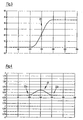
- Fig. 3 shows a movement profile 20 of the turntable, which is generated by the acceleration profile 10.
- the movement takes place from the ordinate value 0 to the ordinate value 45, which in the illustrated example corresponds to a rotation of 45 °. That is, a rotation of the cam drum by 120 ° between the abscissa values 120 and 240 has caused a rotational movement of the turntable of 45 °.
- the velocity oscillations 22a, 22b have marginal amplitudes compared to the maximum amplitude of the velocity profile 22, so that it can be seen what slight effects the oscillations 14, 16 have on an actual movement of the turntable, although its damping effect is as shown in FIG Fig. 2 apparent - is significant.
- Fig. 5 shows the required for generating the acceleration profile 10 profile 24 of a drive torque. Since the amplitudes of the oscillations 14, 16 are very small, only very little drive torque and therefore energy must be applied to their generation. Fig. 5 documented that the required drive torque in the scale shown is negligible.
- Fig. 6 shows a derivative 26 (Jerkkennwert) of the acceleration profile 10 after the plotted in the abscissa A parameter to make some more characteristics of the acceleration profile 10 clear.
- the derivative 26 has four extremes in the region of the input oscillation 14. An absolute minimum or maximum of the first derivative of the input oscillation 14 is reached at its beginning or end.
- the derivative 26 of the réelleoszillation 16 has a symmetrical course (mirroring of the matterssoszillation 14 on a perpendicular to the abscissa in the abscissa value 180).
- the derivative 26 of the main acceleration 12 has a parabolic shape which extends between the absolute maxima of the derivative 26 of the input oscillation 14 and the output oscillation 16. The transition between the input oscillation 14 and the main acceleration 12 or the main acceleration 12 and the output oscillation 16 is thus formed in the first derivative by a respective characteristic "peak".
- main acceleration 12 basically any function (eg a polynomial of arbitrary degree) can be used.
- Fig. 7 shows an acceleration profile 10 'comprising an input oscillation 14', a main acceleration 12 'and an output oscillation 16'.
- the input oscillation 14 'and the output oscillation 16' are in turn symmetrical to one another, but here there is no reflection on the abscissa A, but the output oscillation 16 'is generated by a reflection of the input oscillation 14' on a perpendicular to the abscissa on the abscissa value 180.
- the main acceleration 12 ' has two maxima 12a', 12b 'and a minimum 12c' between the maxima 12a ', 12b', which comprises a horizontal linear segment.
- the damping effect of the oscillations 14 ', 16' is off Fig. 8 seen.
- Fig. 10 illustrates that the effects of the oscillations 12 ', 14' on a speed profile 22 'caused by the acceleration profile 10' are minimal. They cause only weak velocity oscillations 22a ', 22b'.
- Fig. 11 shows an acceleration profile 10 ", which includes an input oscillation 14", a main acceleration 12 "between the rotation angles 120 ° and 240 ° and an output oscillation 16".
- the input oscillation 14 and the output oscillation 16 are again inversely symmetrical.
- the beginning of the main acceleration 12 is characterized by a strong increase, and after reaching an absolute maximum 12a", the acceleration drops again.
- the drop in acceleration to a minimum 12c “includes two inflection points 12d” and a zero crossing at a rotation angle of 180 °.
- Fig. 12 shows the for generating the acceleration profile 10 "required profile 24" of a drive torque.
- the drive torque required to generate the oscillations 14 ", 16" is very low and, in practice, does not lead to any relevant additional energy consumption.
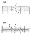
- FIGS. 13 and 14 show the acceleration profile 10 "or the drive torque profile 24", which is superimposed by a simulated parasitic vibration 18 ", as can occur in a real operation of a rotary indexing table.
- Fig. 13 It can clearly be seen that even the input oscillation 14 "leads to a significant damping of the parasitic oscillation 18", so that its influence on the main acceleration 12 "is only comparatively small.
- Fig. 15 shows the drive torque profile 24 "of Fig. 12 in a "stretched” version. It is one in Fig. 16 shown profile 26 "of the jerk characteristic - ie a profile of the first derivative of the acceleration profile 10" - compared.
- Fig. 16 It can be seen that there is a zero crossing of the jerk characteristic at the transitions between the input oscillation 14 "and the main acceleration 12" or between the main acceleration, 12 “and the output oscillation 16" at the angles of rotation 120 ° or 240 °. As a result, the aforementioned transitions are relatively gentle. In contrast, the jerk characteristic profile 26 resulting from the acceleration profile 10 (cf. Fig. 6 ) at these transitions global maxima. Further differentiation of the jerk characteristic profile 26 "- ie the second derivative of the acceleration profile 10" - leads to a curve which is still continuous in the aforementioned transitions.
- Fig. 17 shows a velocity profile 22 "generated by the acceleration profile 10".
- the velocity oscillations 22a “, 22b” caused by the oscillations 14 "and 16", respectively, are only slight, like the corresponding oscillations 22a, 22b, 22a ', 22b' of the velocity profiles 22 and 22 '.
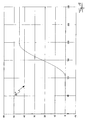
- Fig. 18 shows a motion profile 20 "resulting from the acceleration profile 10". It can be seen that also the acceleration profile 10 "generates only very small movement amplitudes, which are caused by the oscillations 14", 16 ".
- the oscillations 14, 14 '; 14 “, 16, 16 ', 16” have a pronounced damping effect by which the parasitic oscillations 18, 18', 18 "can be suppressed to a great extent, however, the effect of the oscillations 14, 14 ', 14" , 16, 16 ', 16 "to an actual movement of the workpiece minimal, so that the oscillation 14, 14', 16 ', 16, 16', 16” integrate in many cases without problems in known acceleration profiles to let.
- the duration of the oscillations and their course or the number and expression of the maxima and minima can be chosen arbitrarily, in order to achieve the optimum for the particular application case attenuation while minimizing the influence of the main phase / main acceleration.
- the upstream oscillation and the downstream oscillation are preferably symmetrical, it may be advantageous in certain cases if the oscillations are different in their course, their duration and / or their amplitude.
Landscapes
- Engineering & Computer Science (AREA)
- Human Computer Interaction (AREA)
- Manufacturing & Machinery (AREA)
- Physics & Mathematics (AREA)
- General Physics & Mathematics (AREA)
- Automation & Control Theory (AREA)
- Machine Tool Units (AREA)
- Pressure Welding/Diffusion-Bonding (AREA)
Description
- Die vorliegende Erfindung betrifft ein Verfahren zur schwingungsgedämpften rotatorischen und/oder linearen Bewegung eines Werkstücks von einer ersten Ruheposition in eine zweite Ruheposition.
- Bei vielen Produktionsprozessen müssen Werkstücke zwischen einzelnen Produktionsschritten von einer ersten Ruheposition in eine zweite Ruheposition gebracht werden. Bei diesen Ruhepositionen erfolgt beispielsweise jeweils ein Bearbeitungs- und/oder Montageprozess. In der Montage- und Automatisierungstechnik finden beispielsweise Rundschalttische eine breite Anwendung, um eine getaktete Drehbewegung eines Werkstücks zu erzeugen. Dabei ist die Präzision solcher Rundschalttische von besonderer Bedeutung, damit das Werkstück stets wohldefinierte Positionen/Orientierungen relativ zu den Montage-/Bearbeitungswerkzeugen aufweist. Die Präzision der durch den Rundschalttisch erzeugten Bewegung ergibt sich aus der Genauigkeit, mit der ein Teller des Rundschalttischs, auf dem das Werkstück angeordnet ist, die einzelnen Bearbeitungspositionen einnehmen kann, sowie aus der Präzision der Drehbewegung des Tellers zwischen den Ruhe-/ Bearbeitungspositionen. Analoges gilt für Transportvorrichtungen, die lineare Bewegungen zum translatorischen Transport eines Werkstücks zwischen zwei Ruhepositionen erzeugen.
- Ein häufig auftretendes Problem bei Vorrichtungen zur rotatorischen und/oder linearen Bewegung eines Werkstücks sind unerwünschte mechanische Schwingungen, die zu unruhigen Bewegungsabläufen sowie zu Ungenauigkeiten bei der Einnahme der gewünschten Ruhepositionen führen können. Daher wird oft erheblicher Aufwand betrieben, um derartige Schwingungen durch eine geeignete mechanische Auslegung der Komponenten zu vermeiden. Eine solche Vorgehensweise ist aufwändig, kostenintensiv und führt überdies oftmals nur zu unbefriedigenden Ergebnissen.
- Dokument
EP 0 693 333 A1 offenbart ein Verfahren zur Schwingungsdämpfung von angetriebenen Bauteilen von Werkstücktransporteinrichtungen, in dem ein Dämpfungsregelkreis in Ergänzung zu einem Lageregelkreis vorgesehen wird, und wobei die Schwingungsdämpfung durch eine direkte Beeinflussung des Antriebes der angetriebenen Bauteile erfolgt. Zur Ermittlung der Bewegung einer Transferschienenmitte, die schwingungsförmig verlaufen kann, wird eine Zustandsgröße des angetriebenen Bauteils ermittelt, welche in den Dämpfungsregler eingegeben und als Messgröße für den Dämpfungsregler verwendet und von diesem ausgewertet wird. - Es ist eine Aufgabe der vorliegenden Erfindung, ein verbessertes Verfahren zur rotatorischen und/oder linearen Bewegung eines Werkstücks von einer ersten Ruheposition in eine zweite Ruheposition zu schaffen, das eine Dämpfung oder Unterdrückung parasitärer mechanischer Schwingungen bewirkt. Außerdem soll das Verfahren auf einfache Weise zu implementieren sein.
- Diese Aufgabe wird durch ein Verfahren mit den Merkmalen des Anspruchs 1 gelöst.
- Das erfindungsgemäße Verfahren umfasst zumindest eine Eingangsphase und eine beliebige Hauptphase. Während der Eingangsphase wird das Werkstück beschleunigt, wobei die Beschleunigung durch eine erste Funktion definiert ist, die zumindest drei Extrema umfasst, um eine Oszillation des Werkstücks um die erste Ruheposition zu erzeugen. Die beliebige Hauptphase schließt sich an die Eingangsphase an und umfasst die Bewegung des Werkstücks von der ersten Ruheposition in die zweite Ruheposition. Die Bewegung des Werkstücks während der Hauptphase ist durch eine Beschleunigung gemäß einer beliebigen zweiten Funktion definiert.
- Mit anderen Worten umfasst das Beschleunigungsprofil, dem das Werkstück ausgesetzt ist, nicht nur das herkömmlicherweise vorgesehene Beschleunigungsprofil der beliebigen Hauptphase, sondern der eigentlichen Bewegung des Werkstücks ist eine Oszillation um die erste Ruheposition vorgeschaltet. Diese Oszillation bewirkt eine Dämpfung der mechanischen Schwingung der Komponenten der das Verfahren anwendenden Transportvorrichtung. Das Hinzufügen einer solchen Oszillation zu an sich bekannten Beschleunigungsprofilen zur Erzeugung einer Bewegung des Werkstücks ist ohne größeren Aufwand möglich, insbesondere wenn der Bewegungsablauf der Transportvorrichtung durch eine Programmierung eines entsprechenden Steuergeräts frei bestimmt werden kann. Der elegante Grundgedanke der vorliegenden Erfindung, durch kontrollierte kleinskalige und vergleichsweise kurze Oszillationen parasitäre Schwingungen eines Systems zu dämpfen, erfordert in diesen Fällen nicht einmal eine Überarbeitung der verwendeten mechanischen Komponenten.
- Unter Funktionen sind beispielsweise Polynome oder Verknüpfungen von zwei oder mehreren Polynomen zu verstehen.
- Zur Verbesserung der Dämpfung kann sich an die Hauptphase eine Ausgangsphase anschließen, während der das Werkstück erneut beschleunigt wird. Die Beschleunigung des Werkstücks ist in der Ausgangsphase durch eine dritte Funktion definiert, die zumindest drei Extrema umfasst, um eine Oszillation des Werkstücks um die zweite Ruheposition zu erzeugen. Das Beschleunigungsprofil umfasst bei dieser Variante des Verfahrens somit neben der der beliebigen Hauptphase vorgeschalteten Oszillation eine der beliebigen Hauptphase nachgeschaltete Oszillation.
- In bestimmten Fällen kann auch lediglich die nachgeschaltete Oszillation des Werkstücks um die zweite Ruheposition vorgesehen sein. Die vorgeschaltete Oszillation um die erste Ruhelage entfällt dann.
- Grundsätzlich ist es möglich, dass die erste und die dritte Funktion unterschiedlich sind. Bevorzugt sind sie allerdings invers zueinander oder weisen einen gespiegelten Verlauf auf. Eine im allgemeinen Sinne symmetrische Ausgestaltung der ersten und der dritten Funktion (z.B. Spiegelung, Punktsymmetrie,...) hat sich als besonders einfach umsetzbar erwiesen und liefert gleichzeitig gute Dämpfungsergebnisse.
- Vorzugsweise weisen die erste und/oder die - falls vorgesehen - dritte Funktion zumindest ein Segment mit einem konstanten Verlauf auf, d.h. die Beschleunigung des Werkstücks bleibt in diesem Segment gleich. Das genannte Segment bildet vorzugsweise das mittlere konstante Extremum der zumindest drei Extrema.
- Gemäß einer vorteilhaften Ausführungsform des Verfahrens beträgt die maximale Amplitude der durch die Oszillation während der Eingangsphase und/oder - falls vorgesehen - während der Ausgangsphase erzeugten Bewegung des Werkstücks weniger als 0,1 mm auf 100 mm Gesamtweg (etwa 0,1 %), bevorzugt weniger als 0,02 mm auf 100 mm Gesamtweg (etwa 0,02 %) der während der beliebigen Hauptphasen erzeugten Bewegung. Mit anderen Worten oszilliert das Werkstück zwar, die damit verbundenen Bewegungsamplituden sind jedoch minimal und um einige Größenordnungen kleiner als die Amplitude der eigentlichen Transportbewegung. Trotz dieser kaum merkbaren Oszillation, wird eine hinreichend große dämpfende Wirkung erzielt.
- Die erste Funktion und/oder die dritte Funktion (falls vorgesehen) können derart ausgestaltet sein, dass ihre Ableitungen jeweils vier Extrema aufweisen, beispielsweise um eine vorteilhafte Anknüpfung der genannten Funktionen an die beliebige zweite Funktion zu gewährleisten. Insbesondere sind ein Übergang von der ersten Funktion zu der zweiten Funktion und ein Übergang von der zweiten Funktion zu der dritten Funktion - sofern eine Ausgangsphase vorgesehen ist - stetig. Bevorzugt sind auch ein Übergang von einer Ableitung der ersten Funktion zu einer Ableitung der zweiten Funktion und ein Übergang von der Ableitung der zweiten Funktion zu der Ableitung der dritten Funktion stetig. Dadurch wird die Verknüpfung der einzelnen Phasen vereinfacht.
- Alternativ oder zusätzlich können die erste und die zweite Funktion an einem Übergang von der Eingangsphase in die Hauptphase und die zweite und die dritte Funktion an einem Übergang von der Hauptphase in die Ausgangsphase - sofern eine Ausgangsphase vorgesehen ist - jeweils einen Funktionswert von 0 aufweisen (Nulldurchgang der Funktionen).
- Eine für bestimmte Anwendungen besonders geeignete Ausgestaltung des Verfahrens sieht vor, dass die erste und die zweite Funktion an einem Übergang von der Eingangsphase in die Hauptphase und/oder die zweite und die dritte Funktion an einem Übergang von der Hauptphase in die Ausgangsphase jeweils die Steigung 0 aufweisen. Somit bilden die erste und die zweite Funktion bzw. die zweite und die dritte Funktion an den genannten Übergängen lokale Extrema, was letztlich nichts anderes bedeutet, als dass bei den Übergängen zwischen den Phasen keine Beschleunigungen auftreten.
- Mit anderen Worten weisen die erste Ableitung der ersten Funktion und die erste Ableitung der zweiten Funktion an einem Übergang von der Eingangsphase in die Hauptphase und/oder die erste Ableitung der zweiten Funktion und die erste Ableitung der dritten Funktion an einem Übergang von der Hauptphase in die Übergangsphase jeweils einen Wert von 0 auf, um einen sanften Übergang zwischen den einzelnen Phasen zu ermöglichen.
- Die Erfindung betrifft ferner eine Transportvorrichtung mit einem für eine Aufnahme eines Werkstücks geeigneten Transportelement, das rotatorisch und/oder linear von einer ersten Ruheposition in eine zweite Ruheposition bewegbar ist. Die Transportvorrichtung umfasst eine programmierbare Steuervorrichtung, die dazu ausgebildet ist, die Bewegung des Transportelements gemäß einem Verfahren nach zumindest einer der vorstehend beschriebenen Ausführungsformen zu steuern. Das Verfahren lässt sich somit auf einfache Weise durch eine geeignete Programmierung umsetzen.
- Anstelle der programmierbaren Steuervorrichtung kann die vorstehend erwähnte Transportvorrichtung eine mechanische Zwangssteuerung umfassen, die derart ausgebildet ist, dass das Transportelement gemäß einem Verfahren nach zumindest einer der vorstehend beschriebenen Ausführungsformen bewegbar ist. Vorzugsweise ist das Transportelement ein Drehteller, der in eine Antriebsnut einer Kurventrommel eingreifende Mitnehmer aufweist, um durch eine Drehbewegung der Kurventrommel eine zwangsgesteuerte Drehbewegung des Drehtellers zu erzeugen.
- Weitere Ausführungsformen der vorliegenden Erfindung sind in der Beschreibung, den Zeichnungen und den Unteransprüchen angegeben.
- Nachfolgend wird die Erfindung rein beispielhaft anhand vorteilhafter Ausführungsformen unter Bezugnahme auf die Zeichnungen beschrieben. Es zeigen:
- Fig. 1
- ein Beschleunigungsprofil einer Bewegung gemäß einer ersten Ausführungsform des erfindungsgemäßen Verfahrens;
- Fig. 2
- das Beschleunigungsprofil der
Fig. 1 , das von einer simulierten parasitären Schwingung überlagert ist, um die Dämpfungswirkung des erfindungsgemäßen Verfahrens zu verdeutlichen; - Fig. 3
- das sich aus dem Beschleunigungsprofil der
Fig. 1 ergebende Bewegungsprofil; - Fig. 4
- das sich aus dem Beschleunigungsprofil der
Fig. 1 ergebende Geschwindigkeitsprofil; - Fig. 5
- das zur Erzeugung des Beschleunigungsprofils der
Fig. 1 aufzubringende Antriebsmoment; - Fig. 6
- den Verlauf der als Ruckkennwert bezeichneten ersten Ableitung des Beschleunigungsprofils der
Fig. 1 ; - Fig. 7
- ein Beschleunigungsprofil einer Bewegung gemäß einer zweiten Ausführungsform des erfindungsgemäßen Verfahrens;
- Fig. 8
- das Beschleunigungsprofil der
Fig. 7 , das von einer simulierten parasitären Schwingung überlagert ist, um die Dämpfungswirkung des erfindungsgemäßen Verfahrens zu verdeutlichen; - Fig. 9
- das sich aus dem Beschleunigungsprofil der
Fig. 7 ergebende Bewegungsprofil; - Fig. 10
- das sich aus dem Beschleunigungsprofil der
Fig. 7 ergebende Geschwindigkeitsprofil; - Fig. 11
- ein Beschleunigungsprofil einer Bewegung gemäß einer dritten Ausführungsform des erfindungsgemäßen Verfahrens;
- Fig. 12
- das zur Erzeugung des Beschleunigungsprofils der
Fig. 11 aufzubringende Antriebsmoment; - Fig. 13
- das Beschleunigungsprofil der
Fig. 11 , das von einer simulierten parasitären Schwingung überlagert ist, um die Dämpfungswirkung des erfindungsgemäßen Verfahrens zu verdeutlichen; - Fig. 14
- das Profil des Antriebsmoments der
Fig. 12 , das von den in derFig. 13 gezeigten parasitären Schwingungen beeinflusst ist; - Fig. 15 und 16
- das Profil des Antriebsmoments der
Fig. 14 (gestreckt) bzw. den Verlauf der ersten Ableitung des Beschleunigungsprofils derFig. 11 (Ruckkennwert); - Fig. 17
- das sich aus dem Beschleunigungsprofil der
Fig. 11 ergebende Geschwindigkeitsprofil und - Fig. 18
- das sich aus dem Beschleunigungsprofil der
Fig. 11 ergebende Bewegungsprofil. -
Fig. 1 zeigt ein Beschleunigungsprofil 10, das bei einem Rundschalttisch zur schwingungsgedämpften Bewegung eines Werkstücks von einer ersten Ruheposition in eine zweite Ruheposition eingesetzt wird. Die Ordinate O des dargestellten Diagramms ist mit relativen Einheiten versehen, so dass die angegebenen Zahlenwerte lediglich zur Orientierung dienen. Die Abszisse A stellt einen Drehwinkel einer Kurventrommel des Rundschalttischs dar. Die Kurventrommel weist eine Antriebsnut auf, in die Mitnehmer eines Drehtellers eingreifen, der ein zu bewegendes Werkstück aufnimmt. Um eine getaktete rotatorische Bewegung des Drehtellers zu erzeugen, ist die Kurventrommel mit Rastgängen R versehen. Die Rastgänge R définieren die Ruhepositionen des Werkstücks, d.h. zwar dreht sich die Kurventrommel auch während der Rastgänge R um einen bestimmten Drehwinkel (hier 120°), eine wesentliche Bewegung des Drehtellers wird dadurch jedoch nicht erzeugt. Zwischen den Rastgängen R weist die Antriebsnut einen beliebigen Antriebsabschnitt AA auf, der die Drehbewegung des Drehtellers erzeugt, um das Werkstück von der ersten Ruhe-/Bearbeitungsposition in die zweite Ruhe-/Bearbeitungsposition zu bewegen. InFig. 1 sind die Drehwinkelbereiche gekennzeichnet, die von den Rastgängen R bzw. dem Antriebsabschnitt AA überdeckt werden. - In dem dargestellten Beispiel findet die eigentliche Drehbewegung des Drehtellers zwischen einem Drehwinkel von 120° und einem Drehwinkel von 240° der Kurventrommel statt. Es versteht sich, dass die durch die Drehung der Kurventrommel um 120° erzeugte beliebige Bewegung des Drehtellers nicht ebenfalls 120° umfassen muss, sondern in Abhängigkeit der Ausgestaltung der Antriebsnut auch einen größeren oder kleineren Betrag umfassen kann.
- Mit anderen Worten findet bei einem Drehwinkel der Kurventrommel zwischen 0° und 120° und zwischen 240° und 360° (= 0°) im Wesentlichen keine wesentliche Bewegung des Drehtellers statt, was als Rastgang R bezeichnet wird. Aufgrund der zwischen dem Drehwinkel von 120° und dem Drehwinkel von 240° der Kurventrommel erfolgten Beschleunigung des Drehtellers wird eine rotatorische Bewegung erzeugt, die das auf dem Drehteller angeordnete Werkstück aus der ersten Ruheposition in die zweite Ruheposition befördert.
- Es wird darauf hingewiesen, dass das Beschleunigungsprofil nicht zwingend eine Funktion des Drehwinkels einer Kurventrommel sein muss. Bei linearen Bewegungen kann der Beschleunigungsverlauf beispielsweise eine Funktion der Linearposition sein. Auch eine Zeitabhängigkeit ist sowohl bei rotatorischen als auch bei linearen Bewegungen vorstellbar.
- Das Beschleunigungsprofil 10 umfasst eine Hauptbeschleunigung 12 mit einer positiven Beschleunigung zwischen den Abszissenwerten 120 und 180 (Beschleunigen des Drehtellers) und negativen Beschleunigungswerten zwischen den Abszissenwerten 180 und 240 (Abbremsen des Drehtellers). Der Hauptbeschleunigung 12 ist eine Eingangsoszillation 14 vorgeschaltet. Die Eingangsoszillation 14 umfasst ein erstes Minimum 14a und ein zweites Minimum 14b. Dazwischen liegt ein Maximum 14c, das abschnittsweise einen horizontalen, plateauartigen Verlauf aufweist.
- Der Hauptbeschleunigung 12 ist ferner eine Ausgangsoszillation 16 nachgeschaltet. Die Ausgangsoszillation 16 entspricht einer Spiegelung der Eingangsoszillation 14 an der Abszisse A und weist folglich anstelle der Minima 14a, 14b entsprechende Maxima 16a, 16b auf. Das Maximum 14c der Eingangsoszillation 14 findet sich in der Ausgangsoszillation 16 als Minimum 16c wieder, das ebenfalls abschnittsweise einen entsprechenden horizontalen, konstanten Verlauf aufweist. Außerhalb der Eingangsoszillation 14, der Hauptbeschleunigung 12 und der Ausgangsoszillation 16 weist das Beschleunigungsprofil 10 einen Wert von 0 auf, d.h. es liegen keine Beschleunigungen vor.
- Die Verläufe der Eingangsoszillation 14, der Hauptbeschleunigung 12 und der Ausgangsoszillation 16 sind derart ausgestaltet, dass an den jeweiligen Schnittstellen zum einen ein Beschleunigungswert von 0 vorliegt (Nulldurchgang). Zum anderen werden abrupte Beschleunigungsänderungen in dem Bereich der jeweiligen Schnittstellen vermieden, um ein "sanftes" Beschleunigungsprofil zu erhalten.
-
Fig. 2 zeigt beispielhaft in einer Simulation wie eine parasitäre Schwingung 18, die zu Beginn der Simulation "eingespeist" wird, durch das um die Oszillationen 14, 16 ergänzte Beschleunigungsprofil 10 gedämpft wird. Im Verlauf des ersten Rastgangs R nimmt die Amplitude der Schwingung 18 bis zum Abszissenwert 120 ab, was in der Simulation einerseits durch eine mechanische Dämpfung erzeugt wird. Andererseits wirkt sich aber auch ab etwa dem Abszissenwert 90 bereits die Eingangsoszillation 14 dämpfend aus, obwohl die Schwingung 18 anfangs so stark ist, dass der Verlauf der Eingangsoszillation 14 praktisch nicht zu erkennen ist. Der Verlauf der Hauptbeschleunigung 12 wird dahingegen nur noch durch unerwünschte Schwankungen relativ geringer Amplitude gestört. Da die parasitäre Schwingung 18 nach der Hauptbeschleunigung 12 nur noch relativ geringe Amplituden aufweist, ist der Verlauf der Ausgangsoszillation 16 zu erkennen. Sie trägt zu einer weiteren Dämpfung der Schwingung 18 bei, sodass in der zweiten Ruheposition bereits eine stark verringerte Amplitude der Schwingung 18 zu beobachten ist. Schaltet man mehrere Beschleunigungsprofile 10 (Takte) hintereinander, so pendelt sich die Amplitude der Schwingung 18 schnell auf ein sehr geringes Maß ein, das deutlich geringer ist als bei herkömmlichen Beschleunigungsprofilen ohne vor- bzw. nachgeschaltete Oszillationen 14 bzw. 16. In bestimmten Fällen kann es auch ausreichend sein, nur eine der Oszillationen 14, 16 vorzusehen. -
Fig. 3 zeigt ein Bewegungsprofil 20 des Drehtellers, das durch das Beschleunigungsprofil 10 erzeugt wird. Die Bewegung erfolgt dabei von dem Ordinatenwert 0 zu dem Ordinatenwert 45, was in dem dargestellten Beispiel einer Drehung um 45° entspricht. D.h. eine Drehung der Kurventrommel um 120° zwischen den Abszissenwerten 120 und 240 hat eine Drehbewegung des Drehtellers von 45° bewirkt. - Aus
Fig. 3 ist ersichtlich, dass die jeweilige Amplitude der Eingangsoszillation 14 bzw. der Ausgangsoszillation 16 im Vergleich zur Amplitude der durch die Hauptbeschleunigung 12 erzeugten Bewegung vernachlässigbar ist und in dem dargestellten Maßstab nicht zu erkennen ist. Mit anderen Wort "merkt" das bewegte Werkstück praktisch nichts von den schwingungsdämpfend wirkenden Oszillationen 14, 16. - Ein durch das Beschleunigungsprofil 10 erzeugtes Geschwindigkeitsprofil 22, das in
Fig. 4 gezeigt ist, lässt durch die Oszillation 14, 16 erzeugte Geschwindigkeitsoszillationen 22a, 22b erkennen. Die Geschwindigkeitsoszillationen 22a, 22b weisen allerdings im Vergleich zur Maximalamplitude des Geschwindigkeitsprofils 22 marginale Amplituden auf, sodass erkennbar ist, welch geringe Auswirkungen die Oszillationen 14, 16 auf eine tatsächliche Bewegung des Drehtellers haben, obwohl ihr Dämpfungseffekt - wie ausFig. 2 ersichtlich - erheblich ist. -
Fig. 5 zeigt das zur Erzeugung des Beschleunigungsprofils 10 erforderliche Profil 24 eines Antriebsmoments. Da die Amplituden der Oszillationen 14, 16 nur sehr gering sind, muss zu ihrer Erzeugung auch nur sehr wenig Antriebsmoment und damit Energie aufgebracht werden.Fig. 5 dokumentiert, dass das erforderliche Antriebsmoment in dem dargestellten Maßstab vernachlässigbar ist. -
Fig. 6 zeigt eine Ableitung 26 (Ruckkennwert) des Beschleunigungsprofils 10 nach der in der Abszisse A aufgetragenen Parameter, um einige weitere Eigenschaften des Beschleunigungsprofils 10 deutlich zu machen. Die Ableitung 26 weist im Bereich der Eingangsoszillation 14 vier Extrema auf. Ein absolutes Minimum bzw. Maximum der ersten Ableitung der Eingangsoszillation 14 werden an deren Anfang bzw. Ende erreicht. Die Ableitung 26 der Ausgangsoszillation 16 weist einen dazu symmetrischen Verlauf auf (Spiegelung der Eingangsoszillation 14 an einer Senkrechten zu der Abszisse im Abszissenwert 180). Die Ableitung 26 der Hauptbeschleunigung 12 weist einen parabelartigen Verlauf auf, der sich zwischen den absoluten Maxima der Ableitung 26 der Eingangsoszillation 14 bzw. der Ausgangsoszillation 16 erstreckt. Der Übergang zwischen der Eingangsoszillation 14 und der Hauptbeschleunigung 12 bzw. der Hauptbeschleunigung 12 und der Ausgangsoszillation 16 wird in der ersten Ableitung somit durch jeweils eine charakteristische "Spitze" gebildet. - Es ist darauf hinzuweisen, dass als Hauptbeschleunigung 12 im Grunde eine beliebige Funktion (z.B. ein Polynom beliebigen Grades) verwendet werden kann. Die Ausgestaltung der Eingangsoszillation 14 bzw. der Ausgangsoszillation 16, die - anders als dargestellt - grundsätzlich auch vollkommen unterschiedlich ausgestaltet sein können, erlaubt die Einbindung einer Vielzahl von unterschiedlichen Hauptbeschleunigungen 12, die an das jeweils erforderliche Bewegungsprofil angepasst sind.
-
Fig. 7 zeigt ein Beschleunigungsprofil 10', das eine Eingangsoszillation 14', eine Hauptbeschleunigung 12' und eine Ausgangsoszillation 16' umfasst. Die Eingangsoszillation 14' und die Ausgangsoszillation 16' sind wiederum zueinander symmetrisch, allerdings liegt hier keine Spiegelung an der Abszisse A vor, sondern die Ausgangsoszillation 16' wird durch eine Spiegelung der Eingangsoszillation 14' an einer Senkrechten zu der Abszisse am Abszissenwert 180 erzeugt. - Die Hauptbeschleunigung 12' weist zwei Maxima 12a', 12b' und ein zwischen den Maxima 12a', 12b'liegendes Minimum 12c' auf, das ein waagrechtes lineares Segment umfasst. Der Verlauf der Hauptbeschleunigung 12' erzeugt eine Bewegung, die - wie in
Fig. 9 zu sehen ist - ausgehend von der Ruheposition zu dieser zurück führt. Die dämpfende Wirkung der Oszillationen 14', 16' ist ausFig. 8 ersichtlich. -
Fig. 10 verdeutlicht, dass die Auswirkungen der Oszillationen 12', 14' auf ein durch das Beschleunigungsprofil 10' bedingtes Geschwindigkeitsprofil 22' minimal sind. Sie verursachen nur schwach ausgeprägte Geschwindigkeitsoszillationen 22a', 22b'. -
Fig. 11 zeigt ein Beschleunigungsprofil 10", das eine Eingangsoszillation 14", eine Hauptbeschleunigung 12" zwischen den Drehwinkeln 120° und 240° und eine Ausgangsoszillation 16" umfasst. Die Eingangsoszillation 14 und die Ausgangsoszillation 16 sind wiederum invers symmetrisch. - Im Gegensatz zu den vorstehend beschriebenen Beschleunigungsprofilen 10, 10' liegt bei einem Übergang von der Eingangsoszillation 14" zu der Hauptbeschleunigung 12" kein Nulldurchgang vor, sondern das Beschleunigungsprofil 10" weist an diesem Übergang ein lokales Minimum auf. Gleiches gilt für den Übergang zwischen der Hauptbeschleunigung 12" und der Ausgangsoszillation 16". Der Betrag der Beschleunigung ist in diesen Übergängen zwar ebenfalls 0, allerdings liegt kein Verlauf vor, bei dem die Beschleunigung von einem positiven zu einem negativen Wert wechselt oder umgekehrt.
- Der Beginn der Hauptbeschleunigung 12" ist durch einen starken Anstieg charakterisiert. Nach Erreichen eines absoluten Maximums 12a" fällt die Beschleunigung wieder ab. Der Abfall der Beschleunigung bis zu einem Minimum 12c" umfasst zwei Wendepunkte 12d" und einen Nulldurchgang bei einem Drehwinkel von 180°.
-
Fig. 12 zeigt das zur Erzeugung des Beschleunigungsprofils 10" erforderliche Profil 24" eines Antriebsmoments. Wie auch bei den Beschleunigungsprofilen 10, 10' ist das zur Erzeugung der Oszillationen 14", 16" erforderliche Antriebsmoment sehr gering und führt in der Praxis zu keinem relevanten Energiemehrverbrauch. - Die
Fig. 13 und 14 zeigen das Beschleunigungsprofil 10" bzw. das Antriebsmomentprofil 24", das von einer simulierten parasitären Schwingung 18" überlagert wird, wie sie bei einem realen Betrieb eines Rundschalttischs auftreten kann.Fig. 13 ist deutlich zu entnehmen, dass bereits die Eingangsoszillation 14" zu einer signifikanten Dämpfung der parasitären Schwingung 18" führt, sodass deren Einfluss auf die Hauptbeschleunigung 12" nur noch vergleichsweise gering ist. -
Fig. 15 zeigt das Antriebsmomentprofil 24" derFig. 12 in einer "gestreckten" Version. Es ist einem inFig. 16 gezeigten Profil 26" des Ruckkennwerts - also einem Profil der ersten Ableitung des Beschleunigungsprofils 10" - gegenüber gestellt. -
Fig. 16 ist zu entnehmen, dass bei den Übergängen zwischen der Eingangsoszillation 14" und der Hauptbeschleunigung 12" bzw. zwischen der Hauptbeschleunigung, 12" und der Ausgangsoszillation 16" bei den Drehwinkeln 120° bzw. 240° ein Nulldurchgang des Ruckkennwerts vorliegt. Dadurch verlaufen die genannten Übergänge vergleichsweise sanft. Im Gegensatz dazu zeigt das sich aus dem Beschleunigungsprofil 10 ergebende Ruckkennwertprofil 26 (vgl.Fig. 6 ) bei diesen Übergängen globale Maxima. Eine weitere Differenzierung des Ruckkennwertprofils 26" - d.h. die zweite Ableitung des Beschleunigungsprofils 10" - führt zu einem Kurvenverlauf, der in den genannten Übergängen immer noch stetig ist. -
Fig. 17 zeigt ein durch das Beschleunigungsprofil 10" erzeugtes Geschwindigkeitsprofil 22". Die Geschwindigkeitsoszillationen 22a", 22b", die durch die Oszillationen 14" bzw. 16" hervorgerufen werden, sind - wie die entsprechenden Oszillationen 22a, 22b, 22a', 22b' der Geschwindigkeitsprofile 22 bzw. 22' - nur gering. -
Fig. 18 zeigt ein Bewegungsprofil 20", das sich aus dem Beschleunigungsprofil 10" ergibt. Es ist zu erkennen, dass auch das Beschleunigungsprofil 10" nur sehr kleine Bewegungsamplituden erzeugt, die durch die Oszillationen 14", 16" hervorgerufen werden. - Aus den vorstehenden Ausführungen wird deutlich, dass die Oszillationen 14, 14'; 14", 16, 16', 16" zwar einen ausgeprägten dämpfenden Effekt aufweisen, durch den die parasitären Schwingungen 18, 18', 18" zu einem großen Teil unterdrückt werden können. Allerdings ist die Auswirkung der Oszillationen 14, 14', 14", 16, 16', 16" auf eine tatsächliche Bewegung des Werkstücks minimal, sodass sich die Oszillation 14, 14', 16', 16, 16', 16" in sehr vielen Fällen problemlos in bekannte Beschleunigungsprofile integrieren lassen. Die Dauer der Oszillationen sowie deren Verlauf bzw. die Anzahl und Ausprägung der Maxima und Minima kann beliebig gewählt werden, um die für den jeweils vorliegenden Anwendungsfall optimale Dämpfung bei gleichzeitig möglichst geringer Beeinflussung der Haupt-phase/Hauptbeschleunigung zu erreichen. Die vorgeschaltete Oszillation und die nachgeschaltete Oszillation sind zwar bevorzugt symmetrisch, allerdings kann es in bestimmten Fällen vorteilhaft sein, wenn die Oszillationen in ihrem Verlauf, ihrer Dauer und/oder ihrer Amplitude unterschiedlich sind.
-
- 10, 10', 10"
- Beschleunigungsprofil
- 12, 12', 12"
- Hauptbeschleunigung
- 12a', 12b', 12a"
- Maximum
- 12c', 12c"
- Minimum
- 12d"
- Wendepunkt
- 14, 14', 14"
- Eingangsoszillation
- 14a, 14b
- Minimum
- 14c
- Maximum
- 16, 16', 16"
- Ausgangsoszillation
- 16a, 16b
- Maximum
- 16c
- Minimum
- 18, 18', 18"
- parasitäre Schwingung
- 20, 20', 20"
- Bewegungsprofil
- 22, 22', 22"
- Geschwindigkeitsprofil
- 22a, 22b, 22a', 22b', 22a", 22b"
- Geschwindigkeitsoszillation
- 24, 24"
- Antriebsmomentprofil
- 26, 26"
- Ableitung (Ruckkennwert)
- A
- Abszisse
- O
- Ordinate
- AA
- Antriebsabschnitt
- R
- Rastgang
Claims (13)
- Verfahren zur schwingungsgedämpften rotatorischen und/oder linearen Bewegung eines Werkstücks von einer ersten Ruheposition in eine zweiten Ruheposition,
das zumindest eine Eingangsphase und eine Hauptphase umfasst, wobei das Werkstück während der Eingangsphase beschleunigt
wird, wobei die Beschleunigung durch eine erste Funktion (14, 14', 14") definiert ist, die zumindest drei Extrema (14a, 14b, 14c) umfasst, um eine Oszillation des Werkstücks um die erste Ruheposition zu erzeugen, und
wobei sich die die Bewegung des Werkstücks von der ersten Ruheposition in die zweite Ruheposition umfassende Hauptphase an die Eingangsphase anschließt und die Bewegung des Werkstück während der Hauptphase durch eine Beschleunigung gemäß einer zweite Funktion (12, 12', 12") definiert ist. - Verfahren nach Anspruch 1,
dadurch gekennzeichnet, dass
ferner eine Ausgangsphase vorgesehen ist, die sich an die Hauptphase anschließt, wobei das Werkstück während der Ausgangsphase erneut beschleunigt wird, wobei die Beschleunigung durch eine dritte Funktion (16, 16', 16") definiert ist, die zumindest drei Extrema (16a, 16b, 16c) umfasst, um eine Oszillation des Werkstücks um die zweite Ruheposition zu erzeugen. - Verfahren nach Anspruch 2,
dadurch gekennzeichnet, dass
die erste und die dritte Funktion (14, 14', 14" bzw. 16, 16', 16") invers zueinander sind oder einen an einer gemeinsamen Abszisse (A) gespiegelten Verlauf aufweisen. - Verfahren nach Anspruch 1, 2 oder 3,
dadurch gekennzeichnet, dass
die erste Funktion (14, 14') und/oder die dritte Funktion (16, 16') zumindest ein Segment mit einem konstanten Verlauf aufweisen. - Verfahren nach Anspruch 4,
dadurch gekennzeichnet, dass
das Segment mit konstantem Verlauf das mittlere Extremum (14c, 16c) der zumindest drei Extrema bildet. - Verfahren nach zumindest einem der vorstehenden Ansprüche, dadurch gekennzeichnet, dass
die maximale Amplitude der durch die Oszillation während der Eingangsphase und/oder während der Ausgangsphase erzeugten Bewegung des Werkstücks weniger als 0,1 mm auf 100 mm Gesamtweg, bevorzugt weniger als 0,02 mm auf 100 mm Gesamtweg der während der Hauptphase erzeugten Bewegung beträgt. - Verfahren nach zumindest einem der vorstehenden Ansprüche, dadurch gekennzeichnet, dass
die Ableitung (26, 26") der ersten Funktion (14, 14', 14") und/oder die Ableitung (26, 26") der dritten Funktion (16, 16', 16") jeweils vier Extrema aufweisen. - Verfahren nach zumindest einem der vorstehenden Ansprüche, dadurch gekennzeichnet, dass
ein Übergang von der ersten Funktion (14, 14', 14") zu der zweiten Funktion (12, 12', 12") und/oder ein Übergang von der zweiten Funktion (12, 12', 12") zu der dritten Funktion (16, 16', 16") stetig sind. - Verfahren nach zumindest einem der vorstehenden Ansprüche, dadurch gekennzeichnet, dass
die erste und die zweite Funktion (14, 14', 14" bzw. 12, 12', 12") an einem Übergang von der Eingangsphase in die Hauptphase und/oder die zweite und die dritte Funktion (12, 12', 12" bzw. 16, 16', 16") an einem Übergang von der Hauptphase in die Ausgangsphase jeweils einen Funktionswert von 0 aufweisen. - Verfahren nach zumindest einem der vorstehenden Ansprüche, dadurch gekennzeichnet, dass
die erste Ableitung (26") der ersten Funktion (14") und die erste Ableitung (26") der zweiten Funktion (12") an einem Übergang von der Eingangsphase in die Hauptphase und/oder die erste Ableitung (26") der zweiten Funktion (12") und die erste Ableitung (26") der dritte Funktion (16") an einem Übergang von der Hauptphase in die Übergangsphase jeweils einen Wert von 0 aufweisen. - Transportvorrichtung mit einem für eine Aufnahme eines Werkstücks geeigneten Transportelement, das rotatorisch und/oder linear von einer ersten Ruheposition in eine zweite Ruheposition bewegbar ist, wobei die Transportvorrichtung eine programmierbare Steuervorrichtung umfasst, die dazu ausgebildet ist, die Bewegung des Transportelements gemäß einem Verfahren nach zumindest einem der vorstehenden Ansprüche zu steuern.
- Transportvorrichtung mit einem für eine Aufnahme eines Werkstücks geeigneten Transportelement, das rotatorisch und/oder linear von einer ersten Ruheposition in eine zweite Ruheposition bewegbar ist, wobei die Transportvorrichtung eine mechanische Zwangssteuerung umfasst, die derart ausgebildet ist, dass das Transportelement gemäß einem Verfahren nach zumindest einem der vorstehenden Ansprüche bewegt ist.
- Transportvorrichtung nach Anspruch 12,
dadurch gekennzeichnet, dass
das Transportelement ein Drehteller ist, der in eine Antriebsnut einer Kurventrommel eingreifende Mitnehmer aufweist, um durch eine Drehbewegung der Kurventrommel eine zwangsgesteuerte Drehbewegung des Drehtellers zu erzeugen.
Applications Claiming Priority (2)
| Application Number | Priority Date | Filing Date | Title |
|---|---|---|---|
| DE201010013527 DE102010013527A1 (de) | 2010-03-31 | 2010-03-31 | Verfahren zur schwingungsgedämpften Bewegung eines Werkstücks |
| PCT/EP2011/001598 WO2011120684A2 (de) | 2010-03-31 | 2011-03-30 | Verfahren zur schwingungsgedämpften bewegung eines werkstücks |
Publications (2)
| Publication Number | Publication Date |
|---|---|
| EP2539783A2 EP2539783A2 (de) | 2013-01-02 |
| EP2539783B1 true EP2539783B1 (de) | 2014-06-25 |
Family
ID=44512376
Family Applications (1)
| Application Number | Title | Priority Date | Filing Date |
|---|---|---|---|
| EP11711480.1A Not-in-force EP2539783B1 (de) | 2010-03-31 | 2011-03-30 | Verfahren zur schwingungsgedämpften bewegung eines werkstücks |
Country Status (3)
| Country | Link |
|---|---|
| EP (1) | EP2539783B1 (de) |
| DE (1) | DE102010013527A1 (de) |
| WO (1) | WO2011120684A2 (de) |
Families Citing this family (1)
| Publication number | Priority date | Publication date | Assignee | Title |
|---|---|---|---|---|
| DE102017116414A1 (de) * | 2017-07-20 | 2019-01-24 | Weiss Gmbh | Transportvorrichtung zur rotatorischen und/oder linearen bewegung eines werkstücks |
Family Cites Families (5)
| Publication number | Priority date | Publication date | Assignee | Title |
|---|---|---|---|---|
| DE4425739A1 (de) * | 1994-07-21 | 1996-01-25 | Schuler Pressen Gmbh & Co | Verfahren zur Schwingungsdämpfung von angetriebenen Bauteilen von Werkstücktransporteinrichtungen |
| JP4660012B2 (ja) * | 2001-05-21 | 2011-03-30 | 東芝機械株式会社 | 数値制御装置 |
| JP2004341608A (ja) * | 2003-05-13 | 2004-12-02 | Mitsutoyo Corp | 機械装置 |
| JP5082621B2 (ja) * | 2007-06-28 | 2012-11-28 | 株式会社ジェイテクト | 工作物の研削方法及び加工装置 |
| DE102008019742A1 (de) * | 2008-04-19 | 2009-10-22 | Robert Bosch Gmbh | Verfahren zur Dämpfung von Maschinenresonanzen |
-
2010
- 2010-03-31 DE DE201010013527 patent/DE102010013527A1/de not_active Withdrawn
-
2011
- 2011-03-30 WO PCT/EP2011/001598 patent/WO2011120684A2/de not_active Ceased
- 2011-03-30 EP EP11711480.1A patent/EP2539783B1/de not_active Not-in-force
Also Published As
| Publication number | Publication date |
|---|---|
| WO2011120684A3 (de) | 2012-04-05 |
| DE102010013527A1 (de) | 2011-10-06 |
| EP2539783A2 (de) | 2013-01-02 |
| WO2011120684A2 (de) | 2011-10-06 |
Similar Documents
| Publication | Publication Date | Title |
|---|---|---|
| DE10127451B4 (de) | Verfahren zur Steuerung einer Windenergieanlage | |
| DE3587288T2 (de) | Verfahren zur steuerung eines roboters mit mehrfachem gelenk. | |
| DE68927383T2 (de) | Formbefehl-eingabe zum verkleinern unerwünschter dynamik | |
| DE10355614B4 (de) | Einrichtung und Verfahren zur Bewegungsaufteilung einer Bewegung eines Maschinenteils entlang einer Antriebsachse einer Werkzeug- oder Produktionsmaschine | |
| EP1226476B1 (de) | Verfahren und schaltungsanordnung zur erzeugung von lagesollwerten für einen lageregelkreis einer numerisch bahngesteuerten maschine | |
| DE10200680B4 (de) | Minimale Schwingungsanregung beim Verfahren mit Ruckbegrenzung durch Adaption von Ruckprofilen | |
| DE69119573T2 (de) | Steuerungssystem mit gleitender Wirkungsweise | |
| DE102007028934A1 (de) | Verfahren zur optimierten Bewegungskoordination von Mess-oder Werkzeugmaschinen mit redundanten translatorisch wirksamen Achsen | |
| DE102017010539B4 (de) | Vorrichtung und Verfahren zum Steuern einer Werkzeugmaschine, um einen synchronisierten Betrieb einer Spindelachse und einer Vorschubachse zu steuern | |
| DE102016203597A1 (de) | Werkzeugmaschine und Verfahren zur maschinellen Herstellung eines Werkstücks | |
| DE102007027503A1 (de) | Verfahren zur optimierten Bewegungskoordination von Mess- oder Werkzeugmaschinen mit redundanten translatorisch wirksamen Achsen | |
| DE102016012634B4 (de) | Numerische Steuerung mit krümmungs- und krümmungsänderungsabhängiger Geschwindigkeitssteuerung | |
| DE102007006422A1 (de) | Verfahren zum Betreiben von Maschinen mit anpassbaren Bewegungsprofilen | |
| DE102012110227A1 (de) | Motorsteuerungsvorrichtung mit Nullbereichsverarbeitung | |
| DE102009038155A1 (de) | Servomotorsteuergerät | |
| EP3438773A1 (de) | Bearbeitung von werkstücken mit modellgestützter fehlerkompensation | |
| DE112019003996B4 (de) | Bearbeitungsvorrichtung und Schneideverfahren | |
| EP0508994B1 (de) | Verfahren zur steuerung eines über ein proportionalventil verstellbaren stellgliedes | |
| EP2539784B1 (de) | Verfahren zur rotatorischen und/oder linearen bewegung eines werkstücks | |
| DE102010013527A1 (de) | Verfahren zur schwingungsgedämpften Bewegung eines Werkstücks | |
| DE102010013525A1 (de) | Verfahren zur rotatorischen und/oder linearen Bewegung eines Werkstücks | |
| EP2602676A1 (de) | Bestimmen von reibungskomponenten eines antriebssystems | |
| DE102016003640A1 (de) | Laserbearbeitungsvorrichtung mit Abstandssteuerfunktion und Steuerung hierfür | |
| EP1707310B1 (de) | Verfahren zur Erweiterung der Bandbreite eines Antriebssystems mit einem Motor und angekoppelter schwingungsfähiger Mechanik, die vorzugsweise auf Kugelrollspindelsystemen basiert, sowie Vorschubantrieb zur Durchführung eines solchen Verfahrens | |
| DE10043741B4 (de) | Programmierbare Steuereinrichtung |
Legal Events
| Date | Code | Title | Description |
|---|---|---|---|
| PUAI | Public reference made under article 153(3) epc to a published international application that has entered the european phase |
Free format text: ORIGINAL CODE: 0009012 |
|
| 17P | Request for examination filed |
Effective date: 20120927 |
|
| AK | Designated contracting states |
Kind code of ref document: A2 Designated state(s): AL AT BE BG CH CY CZ DE DK EE ES FI FR GB GR HR HU IE IS IT LI LT LU LV MC MK MT NL NO PL PT RO RS SE SI SK SM TR |
|
| DAX | Request for extension of the european patent (deleted) | ||
| GRAP | Despatch of communication of intention to grant a patent |
Free format text: ORIGINAL CODE: EPIDOSNIGR1 |
|
| INTG | Intention to grant announced |
Effective date: 20140108 |
|
| GRAS | Grant fee paid |
Free format text: ORIGINAL CODE: EPIDOSNIGR3 |
|
| GRAA | (expected) grant |
Free format text: ORIGINAL CODE: 0009210 |
|
| AK | Designated contracting states |
Kind code of ref document: B1 Designated state(s): AL AT BE BG CH CY CZ DE DK EE ES FI FR GB GR HR HU IE IS IT LI LT LU LV MC MK MT NL NO PL PT RO RS SE SI SK SM TR |
|
| REG | Reference to a national code |
Ref country code: GB Ref legal event code: FG4D Free format text: NOT ENGLISH |
|
| REG | Reference to a national code |
Ref country code: CH Ref legal event code: EP |
|
| REG | Reference to a national code |
Ref country code: AT Ref legal event code: REF Ref document number: 675049 Country of ref document: AT Kind code of ref document: T Effective date: 20140715 |
|
| REG | Reference to a national code |
Ref country code: IE Ref legal event code: FG4D Free format text: LANGUAGE OF EP DOCUMENT: GERMAN |
|
| REG | Reference to a national code |
Ref country code: CH Ref legal event code: NV Representative=s name: DR. GRAF AND PARTNER AG INTELLECTUAL PROPERTY, CH |
|
| REG | Reference to a national code |
Ref country code: DE Ref legal event code: R096 Ref document number: 502011003551 Country of ref document: DE Effective date: 20140807 |
|
| PG25 | Lapsed in a contracting state [announced via postgrant information from national office to epo] |
Ref country code: NO Free format text: LAPSE BECAUSE OF FAILURE TO SUBMIT A TRANSLATION OF THE DESCRIPTION OR TO PAY THE FEE WITHIN THE PRESCRIBED TIME-LIMIT Effective date: 20140925 Ref country code: FI Free format text: LAPSE BECAUSE OF FAILURE TO SUBMIT A TRANSLATION OF THE DESCRIPTION OR TO PAY THE FEE WITHIN THE PRESCRIBED TIME-LIMIT Effective date: 20140625 Ref country code: LT Free format text: LAPSE BECAUSE OF FAILURE TO SUBMIT A TRANSLATION OF THE DESCRIPTION OR TO PAY THE FEE WITHIN THE PRESCRIBED TIME-LIMIT Effective date: 20140625 Ref country code: CY Free format text: LAPSE BECAUSE OF FAILURE TO SUBMIT A TRANSLATION OF THE DESCRIPTION OR TO PAY THE FEE WITHIN THE PRESCRIBED TIME-LIMIT Effective date: 20140625 Ref country code: GR Free format text: LAPSE BECAUSE OF FAILURE TO SUBMIT A TRANSLATION OF THE DESCRIPTION OR TO PAY THE FEE WITHIN THE PRESCRIBED TIME-LIMIT Effective date: 20140926 |
|
| REG | Reference to a national code |
Ref country code: NL Ref legal event code: VDEP Effective date: 20140625 |
|
| REG | Reference to a national code |
Ref country code: LT Ref legal event code: MG4D |
|
| PG25 | Lapsed in a contracting state [announced via postgrant information from national office to epo] |
Ref country code: LV Free format text: LAPSE BECAUSE OF FAILURE TO SUBMIT A TRANSLATION OF THE DESCRIPTION OR TO PAY THE FEE WITHIN THE PRESCRIBED TIME-LIMIT Effective date: 20140625 Ref country code: HR Free format text: LAPSE BECAUSE OF FAILURE TO SUBMIT A TRANSLATION OF THE DESCRIPTION OR TO PAY THE FEE WITHIN THE PRESCRIBED TIME-LIMIT Effective date: 20140625 Ref country code: SE Free format text: LAPSE BECAUSE OF FAILURE TO SUBMIT A TRANSLATION OF THE DESCRIPTION OR TO PAY THE FEE WITHIN THE PRESCRIBED TIME-LIMIT Effective date: 20140625 Ref country code: RS Free format text: LAPSE BECAUSE OF FAILURE TO SUBMIT A TRANSLATION OF THE DESCRIPTION OR TO PAY THE FEE WITHIN THE PRESCRIBED TIME-LIMIT Effective date: 20140625 |
|
| PG25 | Lapsed in a contracting state [announced via postgrant information from national office to epo] |
Ref country code: CZ Free format text: LAPSE BECAUSE OF FAILURE TO SUBMIT A TRANSLATION OF THE DESCRIPTION OR TO PAY THE FEE WITHIN THE PRESCRIBED TIME-LIMIT Effective date: 20140625 Ref country code: ES Free format text: LAPSE BECAUSE OF FAILURE TO SUBMIT A TRANSLATION OF THE DESCRIPTION OR TO PAY THE FEE WITHIN THE PRESCRIBED TIME-LIMIT Effective date: 20140625 Ref country code: EE Free format text: LAPSE BECAUSE OF FAILURE TO SUBMIT A TRANSLATION OF THE DESCRIPTION OR TO PAY THE FEE WITHIN THE PRESCRIBED TIME-LIMIT Effective date: 20140625 Ref country code: PT Free format text: LAPSE BECAUSE OF FAILURE TO SUBMIT A TRANSLATION OF THE DESCRIPTION OR TO PAY THE FEE WITHIN THE PRESCRIBED TIME-LIMIT Effective date: 20141027 Ref country code: SK Free format text: LAPSE BECAUSE OF FAILURE TO SUBMIT A TRANSLATION OF THE DESCRIPTION OR TO PAY THE FEE WITHIN THE PRESCRIBED TIME-LIMIT Effective date: 20140625 Ref country code: RO Free format text: LAPSE BECAUSE OF FAILURE TO SUBMIT A TRANSLATION OF THE DESCRIPTION OR TO PAY THE FEE WITHIN THE PRESCRIBED TIME-LIMIT Effective date: 20140625 |
|
| PG25 | Lapsed in a contracting state [announced via postgrant information from national office to epo] |
Ref country code: PL Free format text: LAPSE BECAUSE OF FAILURE TO SUBMIT A TRANSLATION OF THE DESCRIPTION OR TO PAY THE FEE WITHIN THE PRESCRIBED TIME-LIMIT Effective date: 20140625 Ref country code: NL Free format text: LAPSE BECAUSE OF FAILURE TO SUBMIT A TRANSLATION OF THE DESCRIPTION OR TO PAY THE FEE WITHIN THE PRESCRIBED TIME-LIMIT Effective date: 20140625 Ref country code: IS Free format text: LAPSE BECAUSE OF FAILURE TO SUBMIT A TRANSLATION OF THE DESCRIPTION OR TO PAY THE FEE WITHIN THE PRESCRIBED TIME-LIMIT Effective date: 20141025 |
|
| REG | Reference to a national code |
Ref country code: DE Ref legal event code: R097 Ref document number: 502011003551 Country of ref document: DE |
|
| PG25 | Lapsed in a contracting state [announced via postgrant information from national office to epo] |
Ref country code: DK Free format text: LAPSE BECAUSE OF FAILURE TO SUBMIT A TRANSLATION OF THE DESCRIPTION OR TO PAY THE FEE WITHIN THE PRESCRIBED TIME-LIMIT Effective date: 20140625 |
|
| PLBE | No opposition filed within time limit |
Free format text: ORIGINAL CODE: 0009261 |
|
| STAA | Information on the status of an ep patent application or granted ep patent |
Free format text: STATUS: NO OPPOSITION FILED WITHIN TIME LIMIT |
|
| 26N | No opposition filed |
Effective date: 20150326 |
|
| PG25 | Lapsed in a contracting state [announced via postgrant information from national office to epo] |
Ref country code: MC Free format text: LAPSE BECAUSE OF FAILURE TO SUBMIT A TRANSLATION OF THE DESCRIPTION OR TO PAY THE FEE WITHIN THE PRESCRIBED TIME-LIMIT Effective date: 20140625 Ref country code: LU Free format text: LAPSE BECAUSE OF FAILURE TO SUBMIT A TRANSLATION OF THE DESCRIPTION OR TO PAY THE FEE WITHIN THE PRESCRIBED TIME-LIMIT Effective date: 20150330 |
|
| PG25 | Lapsed in a contracting state [announced via postgrant information from national office to epo] |
Ref country code: SI Free format text: LAPSE BECAUSE OF FAILURE TO SUBMIT A TRANSLATION OF THE DESCRIPTION OR TO PAY THE FEE WITHIN THE PRESCRIBED TIME-LIMIT Effective date: 20140625 |
|
| REG | Reference to a national code |
Ref country code: IE Ref legal event code: MM4A |
|
| PG25 | Lapsed in a contracting state [announced via postgrant information from national office to epo] |
Ref country code: IE Free format text: LAPSE BECAUSE OF NON-PAYMENT OF DUE FEES Effective date: 20150330 |
|
| REG | Reference to a national code |
Ref country code: FR Ref legal event code: PLFP Year of fee payment: 6 |
|
| PGFP | Annual fee paid to national office [announced via postgrant information from national office to epo] |
Ref country code: CH Payment date: 20160323 Year of fee payment: 6 |
|
| PGFP | Annual fee paid to national office [announced via postgrant information from national office to epo] |
Ref country code: FR Payment date: 20160321 Year of fee payment: 6 Ref country code: GB Payment date: 20160321 Year of fee payment: 6 |
|
| PGFP | Annual fee paid to national office [announced via postgrant information from national office to epo] |
Ref country code: DE Payment date: 20160530 Year of fee payment: 6 |
|
| PGFP | Annual fee paid to national office [announced via postgrant information from national office to epo] |
Ref country code: IT Payment date: 20160324 Year of fee payment: 6 |
|
| PG25 | Lapsed in a contracting state [announced via postgrant information from national office to epo] |
Ref country code: MT Free format text: LAPSE BECAUSE OF FAILURE TO SUBMIT A TRANSLATION OF THE DESCRIPTION OR TO PAY THE FEE WITHIN THE PRESCRIBED TIME-LIMIT Effective date: 20140625 |
|
| REG | Reference to a national code |
Ref country code: AT Ref legal event code: MM01 Ref document number: 675049 Country of ref document: AT Kind code of ref document: T Effective date: 20160330 |
|
| PG25 | Lapsed in a contracting state [announced via postgrant information from national office to epo] |
Ref country code: HU Free format text: LAPSE BECAUSE OF FAILURE TO SUBMIT A TRANSLATION OF THE DESCRIPTION OR TO PAY THE FEE WITHIN THE PRESCRIBED TIME-LIMIT; INVALID AB INITIO Effective date: 20110330 Ref country code: SM Free format text: LAPSE BECAUSE OF FAILURE TO SUBMIT A TRANSLATION OF THE DESCRIPTION OR TO PAY THE FEE WITHIN THE PRESCRIBED TIME-LIMIT Effective date: 20140625 Ref country code: BG Free format text: LAPSE BECAUSE OF FAILURE TO SUBMIT A TRANSLATION OF THE DESCRIPTION OR TO PAY THE FEE WITHIN THE PRESCRIBED TIME-LIMIT Effective date: 20140625 |
|
| PG25 | Lapsed in a contracting state [announced via postgrant information from national office to epo] |
Ref country code: BE Free format text: LAPSE BECAUSE OF NON-PAYMENT OF DUE FEES Effective date: 20150331 |
|
| PG25 | Lapsed in a contracting state [announced via postgrant information from national office to epo] |
Ref country code: TR Free format text: LAPSE BECAUSE OF FAILURE TO SUBMIT A TRANSLATION OF THE DESCRIPTION OR TO PAY THE FEE WITHIN THE PRESCRIBED TIME-LIMIT Effective date: 20140625 Ref country code: AT Free format text: LAPSE BECAUSE OF NON-PAYMENT OF DUE FEES Effective date: 20160330 |
|
| REG | Reference to a national code |
Ref country code: DE Ref legal event code: R119 Ref document number: 502011003551 Country of ref document: DE |
|
| REG | Reference to a national code |
Ref country code: CH Ref legal event code: PL |
|
| GBPC | Gb: european patent ceased through non-payment of renewal fee |
Effective date: 20170330 |
|
| REG | Reference to a national code |
Ref country code: FR Ref legal event code: ST Effective date: 20171130 |
|
| PG25 | Lapsed in a contracting state [announced via postgrant information from national office to epo] |
Ref country code: DE Free format text: LAPSE BECAUSE OF NON-PAYMENT OF DUE FEES Effective date: 20171003 Ref country code: FR Free format text: LAPSE BECAUSE OF NON-PAYMENT OF DUE FEES Effective date: 20170331 |
|
| PG25 | Lapsed in a contracting state [announced via postgrant information from national office to epo] |
Ref country code: GB Free format text: LAPSE BECAUSE OF NON-PAYMENT OF DUE FEES Effective date: 20170330 Ref country code: LI Free format text: LAPSE BECAUSE OF NON-PAYMENT OF DUE FEES Effective date: 20170331 Ref country code: IT Free format text: LAPSE BECAUSE OF NON-PAYMENT OF DUE FEES Effective date: 20170330 Ref country code: CH Free format text: LAPSE BECAUSE OF NON-PAYMENT OF DUE FEES Effective date: 20170331 |
|
| PG25 | Lapsed in a contracting state [announced via postgrant information from national office to epo] |
Ref country code: MK Free format text: LAPSE BECAUSE OF FAILURE TO SUBMIT A TRANSLATION OF THE DESCRIPTION OR TO PAY THE FEE WITHIN THE PRESCRIBED TIME-LIMIT Effective date: 20140625 |
|
| PG25 | Lapsed in a contracting state [announced via postgrant information from national office to epo] |
Ref country code: AL Free format text: LAPSE BECAUSE OF FAILURE TO SUBMIT A TRANSLATION OF THE DESCRIPTION OR TO PAY THE FEE WITHIN THE PRESCRIBED TIME-LIMIT Effective date: 20140625 |