EP2539190B1 - Method for controlling an occupant protection system using input from a sensor of a stability control system - Google Patents
Method for controlling an occupant protection system using input from a sensor of a stability control system Download PDFInfo
- Publication number
- EP2539190B1 EP2539190B1 EP10760239.3A EP10760239A EP2539190B1 EP 2539190 B1 EP2539190 B1 EP 2539190B1 EP 10760239 A EP10760239 A EP 10760239A EP 2539190 B1 EP2539190 B1 EP 2539190B1
- Authority
- EP
- European Patent Office
- Prior art keywords
- occupant protection
- sensor
- signal
- protection system
- stability control
- Prior art date
- Legal status (The legal status is an assumption and is not a legal conclusion. Google has not performed a legal analysis and makes no representation as to the accuracy of the status listed.)
- Active
Links
- 238000000034 method Methods 0.000 title claims description 17
- 230000001133 acceleration Effects 0.000 claims description 46
- 238000012545 processing Methods 0.000 claims description 12
- 238000001914 filtration Methods 0.000 claims description 5
- 230000010354 integration Effects 0.000 claims description 3
- 230000004888 barrier function Effects 0.000 description 5
- 238000012935 Averaging Methods 0.000 description 2
- 238000011156 evaluation Methods 0.000 description 2
- 241001295925 Gegenes Species 0.000 description 1
- 230000005540 biological transmission Effects 0.000 description 1
- 230000003750 conditioning effect Effects 0.000 description 1
- 230000001419 dependent effect Effects 0.000 description 1
- 238000011161 development Methods 0.000 description 1
- 230000018109 developmental process Effects 0.000 description 1
- 238000002474 experimental method Methods 0.000 description 1
- 230000011664 signaling Effects 0.000 description 1
- 239000007787 solid Substances 0.000 description 1
- 230000001360 synchronised effect Effects 0.000 description 1
- 230000009466 transformation Effects 0.000 description 1
- 230000001960 triggered effect Effects 0.000 description 1
- 238000009966 trimming Methods 0.000 description 1
Images


Classifications
-
- B—PERFORMING OPERATIONS; TRANSPORTING
- B60—VEHICLES IN GENERAL
- B60R—VEHICLES, VEHICLE FITTINGS, OR VEHICLE PARTS, NOT OTHERWISE PROVIDED FOR
- B60R25/00—Fittings or systems for preventing or indicating unauthorised use or theft of vehicles
-
- B—PERFORMING OPERATIONS; TRANSPORTING
- B60—VEHICLES IN GENERAL
- B60W—CONJOINT CONTROL OF VEHICLE SUB-UNITS OF DIFFERENT TYPE OR DIFFERENT FUNCTION; CONTROL SYSTEMS SPECIALLY ADAPTED FOR HYBRID VEHICLES; ROAD VEHICLE DRIVE CONTROL SYSTEMS FOR PURPOSES NOT RELATED TO THE CONTROL OF A PARTICULAR SUB-UNIT
- B60W50/00—Details of control systems for road vehicle drive control not related to the control of a particular sub-unit, e.g. process diagnostic or vehicle driver interfaces
- B60W50/04—Monitoring the functioning of the control system
-
- B—PERFORMING OPERATIONS; TRANSPORTING
- B60—VEHICLES IN GENERAL
- B60R—VEHICLES, VEHICLE FITTINGS, OR VEHICLE PARTS, NOT OTHERWISE PROVIDED FOR
- B60R21/00—Arrangements or fittings on vehicles for protecting or preventing injuries to occupants or pedestrians in case of accidents or other traffic risks
- B60R21/01—Electrical circuits for triggering passive safety arrangements, e.g. airbags, safety belt tighteners, in case of vehicle accidents or impending vehicle accidents
- B60R2021/01122—Prevention of malfunction
- B60R2021/01184—Fault detection or diagnostic circuits
- B60R2021/0119—Plausibility check
-
- B—PERFORMING OPERATIONS; TRANSPORTING
- B60—VEHICLES IN GENERAL
- B60T—VEHICLE BRAKE CONTROL SYSTEMS OR PARTS THEREOF; BRAKE CONTROL SYSTEMS OR PARTS THEREOF, IN GENERAL; ARRANGEMENT OF BRAKING ELEMENTS ON VEHICLES IN GENERAL; PORTABLE DEVICES FOR PREVENTING UNWANTED MOVEMENT OF VEHICLES; VEHICLE MODIFICATIONS TO FACILITATE COOLING OF BRAKES
- B60T2270/00—Further aspects of brake control systems not otherwise provided for
- B60T2270/40—Failsafe aspects of brake control systems
- B60T2270/413—Plausibility monitoring, cross check, redundancy
-
- B—PERFORMING OPERATIONS; TRANSPORTING
- B60—VEHICLES IN GENERAL
- B60W—CONJOINT CONTROL OF VEHICLE SUB-UNITS OF DIFFERENT TYPE OR DIFFERENT FUNCTION; CONTROL SYSTEMS SPECIALLY ADAPTED FOR HYBRID VEHICLES; ROAD VEHICLE DRIVE CONTROL SYSTEMS FOR PURPOSES NOT RELATED TO THE CONTROL OF A PARTICULAR SUB-UNIT
- B60W50/00—Details of control systems for road vehicle drive control not related to the control of a particular sub-unit, e.g. process diagnostic or vehicle driver interfaces
- B60W2050/0001—Details of the control system
- B60W2050/0002—Automatic control, details of type of controller or control system architecture
- B60W2050/0008—Feedback, closed loop systems or details of feedback error signal
- B60W2050/001—Proportional integral [PI] controller
-
- B—PERFORMING OPERATIONS; TRANSPORTING
- B60—VEHICLES IN GENERAL
- B60W—CONJOINT CONTROL OF VEHICLE SUB-UNITS OF DIFFERENT TYPE OR DIFFERENT FUNCTION; CONTROL SYSTEMS SPECIALLY ADAPTED FOR HYBRID VEHICLES; ROAD VEHICLE DRIVE CONTROL SYSTEMS FOR PURPOSES NOT RELATED TO THE CONTROL OF A PARTICULAR SUB-UNIT
- B60W50/00—Details of control systems for road vehicle drive control not related to the control of a particular sub-unit, e.g. process diagnostic or vehicle driver interfaces
- B60W2050/0001—Details of the control system
- B60W2050/0043—Signal treatments, identification of variables or parameters, parameter estimation or state estimation
- B60W2050/0052—Filtering, filters
Definitions
- the invention relates to a method for controlling an occupant protection system taking into account at least one signal from at least one sensor of the occupant protection system and at least one signal of at least one sensor of a vehicle dynamics control.
- WO 2006/122742 describes the WO 2006/122742 the control of an occupant protection means taking into account driving state data, which are also used for the vehicle dynamics control system.
- DE 10 2004 038 000 A1 a method for controlling an occupant protection system, in particular a method for determining a tilt angle for detecting a rollover process, refer to which also signals from sensors for driving dynamics control (ESP) are used to check whether the signals from the sensors of the occupant protection system are plausible and can therefore be used to control the occupant protection system.
- ESP driving dynamics control
- the sensors for vehicle dynamics control are designed for other signal characteristics and their sensor-internal signal conditioning optimized accordingly than sensors for the occupant protection system.
- the signals are thus not readily comparable and it was therefore previously required a very complex signal evaluation.
- a redundant check and plausibility of the sensor signals is increasingly required for the control of an occupant protection system.
- additional, for example outsourced in the vehicle exterior sensors can detect an accident earlier in time, however, have significant additional costs due to the additional sensors and in particular the required wiring through the entire vehicle.
- This document discloses a method for controlling an occupant protection system taking into account a signal from a sensor of the occupant protection system and a signal from a vehicle dynamics control sensor, both sensors measuring the lateral acceleration, the signal from the vehicle dynamics control sensor being provided to the occupant protection system, and subsequently the deviation of the two Signals from each other with a tolerance threshold is compared.
- the object of the present invention is therefore to provide a method for controlling an occupant protection system taking into account at least one signal of at least one sensor of a vehicle dynamics control, which at the same time allows a safe plausibility check, but on the other hand is easy to implement.
- the signal of the sensor of the occupant protection system is also processed with the signal processing steps, which are contained in the sensor for vehicle dynamics control, be it by properties of the sensor element itself or sensor-internal signal processing.
- the clearly high-frequency and amplitude-amplified mapped acceleration signal of the occupant protection system is filtered accordingly, for example by appropriate signal processing and clipped in amplitude as it is already sensorintem provided in the sensor for driving dynamics control. Both signals are then much better comparable.
- the deviation of the two signals from one another can be integrated over a time window and this integrated deviation can be compared with a tolerance threshold. This integration allows even short-term deviations to be better compensated and a longer plausible phase to be obtained overall.
- a summation of digital sensor values or an averaging are considered to be equivalent and to be covered by the teaching of the claim.
- the acceleration signals in a first direction had implausible time ranges precisely when high signal amplitudes occurred in the direction perpendicular thereto.
- the first acceleration signal of the occupant protection system can therefore be assessed as plausible even if the tolerance threshold is exceeded if the second acceleration signal or a variable derived therefrom exceeds a predetermined threshold, ie, for example, implausible regions of the two lateral acceleration signals are explained to one another by a correspondingly strong X acceleration signal.
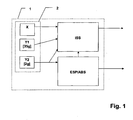
- FIG. 1 shows a common control unit 1 for occupant protection system and vehicle dynamics control with a first functional block ISS for the occupant protection system and a second functional block ABS / ESP for vehicle dynamics control.
- a common sensor cluster 2 is provided with sensors for both the occupant protection system and the vehicle dynamics control within the common control unit 1, of course, the sensor cluster 2 or individual sensors can be arranged spatially spaced at different positions in the vehicle.
- the sensor cluster 2 has an acceleration sensor X in the direction of travel and an acceleration sensor Y1 in the transverse direction for the occupant protection system with an amplitude resolution of up to 35 g.
- the acceleration signals in the travel and transverse directions could also be generated by coordinate transformation from deviating sensors, for example 45 degrees offset sensors, and provided to the algorithm.
- a second acceleration sensor Y2 is provided in the transverse direction for the driving dynamics control, which has the usual limitations for dynamic driving sensors, ie in particular a limitation of the signal amplitude to here, for example, 2g and low-pass filtering.
- This signal from the acceleration sensor Y2 is, as sketched in the FIG. 1 indicated either provided directly from the sensor to the function block ISS for the occupant protection system or forwarded via the function block ABS / ESP the vehicle dynamics control to the function block ISS for the occupant protection system.
- the signal of the sensor of the vehicle dynamics control is usually processed already sensorintem by a low-pass filtering and a limitation of the signal amplitude
- the signal of the sensor of the occupant protection system preferably in the control unit of the occupant protection system also processed with this or this predetermined signal processing step (s) and thus designed comparable to the signal of the sensor of the vehicle dynamics control.
- the signal of the sensor of the occupant protection system preferably in the control unit of the occupant protection system also processed with this or this predetermined signal processing step (s) and thus designed comparable to the signal of the sensor of the vehicle dynamics control.
- a 2-pole Bessel filtering with a cutoff frequency of 50 Hz and an amplitude limit to 2g as well suited to win a signal comparable to the signal of the vehicle dynamics control signal from the signal of the sensor of the occupant protection system.
- other filters can also be used.
- the aim is to imitate the driving dynamics signal with the crash sensor.
- the deviation of the two signals from each other is summed or integrated with a tolerance threshold compared and evaluated within the tolerance threshold, the signals as plausible. Since short-term deviations can never be ruled out, but are insignificant for the control, it is advisable to integrate the deviations over a sliding time window or to summate them just equivalently for digital signal values.
- a sliding time window is used in this embodiment with 4 ms, with time windows below 10 ms are to be preferred in order to respond to the dynamic signals sufficiently fast.
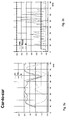
- FIGS. 2 to 7 show in each case signal waveforms at different collision types and thereby provided plausibility of the lateral acceleration signals Y1, Y2 optionally taking into account the acceleration signal X.
- the lateral acceleration on the sensor of the occupant protection system is shown in dashed lines as Y1 after its filtering and trimming to the 2g limit, the solid curve shows the lateral acceleration signal of the vehicle dynamics sensor, which is already inside the sensor due to the so limited signal range of the vehicle Sensor is only converted to 2g.
- the significantly coarser resolution of the sensor Y1 of the occupant protection system in the range up to 2 g additionally leads to a certain, tolerable deviation.
- the signal of the acceleration sensor X of the occupant protection system is indicated in the direction of travel, which can indeed be used for the evaluation of implausible areas.
- the signal X is preferably also trimmed to 2g.
- the acceleration with a sign is shown as fluctuating around the zero line between + 2g and -2g, wherein the assignment of the positive direction in the lateral acceleration sensors Y1 and Y2 to the right and left sides is insignificant.
- the signal X represents positive accelerations in the direction of travel as positive, that is to say in the case of a frontal crash, correspondingly negative accelerations in the X direction are represented.
- the course of the integrated deviation signal is shown dotted. That is, the deviations from the acceleration signal Y1 to the acceleration signal Y2 are summed over a sliding time window of, for example, 4 ms and compared with the maximum threshold shown in dashed lines. If this maximum threshold is exceeded, the acceleration signals Y1 and Y2 are no longer plausible.
- the plausibility assessment is shown as a solid line, whereby the value 0 characterizes an implausible range and the value 1 indicates the plausibility.
- FIG. 2 shows an example of the waveforms of a typically serious Misuses (60km / h, curb crossing). This shows deviations of the signals Y1 and Y2 and was therefore used for the parameterization of the plausibility criterion. While an impact at this speed and at this angle to a larger obstacle clearly leads to a tripping, it also comes in a curb crossing to significant acceleration signals in the direction of travel and transverse direction, but it is still no trigger the occupant protection device.
- the lateral acceleration signals Y1 and Y2 have a very similar course, so that the course of the time window integral ⁇ on the difference of these two signals (in FIG. 2b dotted) does not exceed the maximum threshold (Max) and thus the plausibility signal (Plausi - solid line) always maintains the value 1 associated with the fulfilled sensor plausibility. The plausibility is thus fulfilled for the entire duration of this misuse (see Fig. 2b ).
- FIG. 3 now shows in comparison to the waveforms in a side vehicle-vehicle collision, in which therefore a second vehicle ramming the side of the vehicle with the occupant protection system.
- Clearly recognizable are the relatively strong, synchronous excursions of the two acceleration signals, the deviations over the time window remain integrated within the maximum threshold.
- the lateral acceleration signals are thus plausible to one another over the entire course of the crash and allow the deployment of the occupant protection devices, in particular the side airbags.
- FIG. 4 shows analogously to FIG. 3 a classic side impact, trigger case: collision with a deformable barrier. As in FIG. 4a marked circled, occurs in a time range of about 35-45 ms from the beginning of the crash on a significant deviation of the lateral acceleration signal Y2 of the vehicle dynamics control. However, since the triggering decision could be made at a much earlier point in time by the system, the plausibility in this time range has no consequences for the triggering behavior.
- Fig. 5 now shows the signal curves in a lateral pile impact on the rear row of seats. It should be emphasized again here that the course of the lateral acceleration signals Y1 and Y2 is plausible at least in the time range which is decisive for the triggering and the implausible time range is also characterized by a strong X signal.
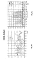
- Fig. 6 shows the signal curves in a partially overlapping head-on collision with a deformable obstacle (ODB - Offset deformable barrier). Partial overlap results in significant signal components in the lateral acceleration signals Y1 and Y2 despite the collision in the direction of travel. Although the lateral acceleration signals in the marked area deviate so far from each other here that the plausibility is not given, however, this time range is clearly after the time range decisive for the triggering (up to approximately 30 ms). In addition, the strong signal X can be used in the direction of travel for plausibility.
- Fig. 7 still shows the waveforms in a frontal wall collision.
- significant signal components of the lateral acceleration signals occur, which in turn, however, are plausible to one another in the triggering time domain.
- the later implausible areas are clearly after the triggering time and could also be made plausible by a strong X-signal.
- This method is thus suitable for a vehicle with a control unit for an occupant protection system and a spatially separate control unit for the vehicle dynamics control as well as for a common control unit for occupant protection system and vehicle dynamics control.
- the method may be used to validate the lateral acceleration signal of the occupant protection system without requiring paged side sensors. This considerably reduces the costs of the occupant protection system without having to forego the desired plausibility check.
- the method is applicable both for sensors for the occupant protection system and spaced at different positions in the vehicle arranged sensors for the vehicle dynamics control as well as a system with crash and driving dynamics sensor at a common location in the vehicle.
- the arrangement of the sensors in a common control unit for vehicle dynamics and crash sensor technology (sensor cluster) is possible.
Description
Die Erfindung betrifft ein Verfahren zur Steuerung eines Insassenschutzsystems unter Berücksichtigung zumindest eines Signals von zumindest einem Sensor des Insassenschutzsystems sowie zumindest eines Signals zumindest eines Sensors einer Fahrdynamiksteuerung.The invention relates to a method for controlling an occupant protection system taking into account at least one signal from at least one sensor of the occupant protection system and at least one signal of at least one sensor of a vehicle dynamics control.
So beschreibt beispielsweise die
Grundsätzlich wird für die Steuerung eines Insassenschutzsystems zunehmend eine redundante Überprüfung und Plausibilisierung der Sensorsignale gefordert. Zusätzliche, beispielsweise in den Fahrzeug-Außenbereich ausgelagerte Sensoren können zwar einen Unfall zeitlich früher erkennen, weisen jedoch erhebliche Mehrkosten aufgrund der zusätzlichen Sensoren und insbesondere auch der erforderlichen Verkabelung durch das gesamte Fahrzeug auf.Basically, a redundant check and plausibility of the sensor signals is increasingly required for the control of an occupant protection system. Although additional, for example outsourced in the vehicle exterior sensors can detect an accident earlier in time, however, have significant additional costs due to the additional sensors and in particular the required wiring through the entire vehicle.
So ist aus der
Dieses Dokument offenbart ein Verfahren zur Steuerung eines Insassenschutzsystems unter Berücksichtigung eines Signals von einem Sensor des Insassenschutzsystems sowie eines Signals eines Sensors einer Fahrdynamiksteuerung, wobei beide Sensoren die Querbeschleunigung messen, wobei das Signal des Sensors der Fahrdynamiksteuerung dem Insassenschutzsystem bereitgestellt wird und nachfolgend die Abweichung der beiden Signale voneinander mit einer Toleranzschwelle verglichen wird.This document discloses a method for controlling an occupant protection system taking into account a signal from a sensor of the occupant protection system and a signal from a vehicle dynamics control sensor, both sensors measuring the lateral acceleration, the signal from the vehicle dynamics control sensor being provided to the occupant protection system, and subsequently the deviation of the two Signals from each other with a tolerance threshold is compared.
Die Aufgabe der vorliegenden Erfindung ist es daher, ein Verfahren zur Steuerung eines Insassenschutzsystems unter Berücksichtigung zumindest eines Signals zumindest eines Sensors einer Fahrdynamiksteuerung anzugeben, welches zugleich eine sichere Plausibilisierung ermöglicht, andererseits aber einfach zu realisieren ist.The object of the present invention is therefore to provide a method for controlling an occupant protection system taking into account at least one signal of at least one sensor of a vehicle dynamics control, which at the same time allows a safe plausibility check, but on the other hand is easy to implement.
Diese Aufgabe wird durch die Merkmale der unabhängigen Ansprüche gelöst. Vorteilhafte Weiterbildungen der Erfindung ergeben sind aus den Unteransprüchen.This object is solved by the features of the independent claims. Advantageous developments of the invention will become apparent from the dependent claims.
Ein wesentlicher Gedanke der Erfindung besteht darin, dass das Signal des Sensors des Insassenschutzsystems ebenfalls mit den Signalverarbeitungsschritten bearbeitet wird, welche im Sensor für die Fahrdynamiksteuerung, sei es durch Eigenschaften des Sensorelementes selbst oder sensorinterne Signalverarbeitung enthalten sind. So wird also das deutlich hochfrequenter und amplitudenstärker abgebildete Beschleunigungssignal des Insassenschutzsystems beispielsweise durch entsprechende Signalverarbeitung entsprechend gefiltert und in seiner Amplitude so beschnitten, wie dies im Sensor für Fahrdynamiksteuerung bereits sensorintem vorgesehen ist. Beide Signale sind danach aber jedoch deutlich besser vergleichbar. Insbesondere kann nachfolgend die Abweichung der beiden Signale voneinander über ein Zeitfenster integriert und diese integrierte Abweichung mit einer Toleranzschwelle verglichen werden. Durch diese Integration können kurzzeitige Abweichungen noch besser ausgeglichen und eine insgesamt längere plausible Phase erhalten werden. Eine Summation digitaler Sensorwerte oder eine Mittelwertbildung sind dabei als äquivalent und mit von der Lehre des Anspruchs umfasst zu betrachten.An essential idea of the invention is that the signal of the sensor of the occupant protection system is also processed with the signal processing steps, which are contained in the sensor for vehicle dynamics control, be it by properties of the sensor element itself or sensor-internal signal processing. Thus, the clearly high-frequency and amplitude-amplified mapped acceleration signal of the occupant protection system is filtered accordingly, for example by appropriate signal processing and clipped in amplitude as it is already sensorintem provided in the sensor for driving dynamics control. Both signals are then much better comparable. In particular, subsequently, the deviation of the two signals from one another can be integrated over a time window and this integrated deviation can be compared with a tolerance threshold. This integration allows even short-term deviations to be better compensated and a longer plausible phase to be obtained overall. A summation of digital sensor values or an averaging are considered to be equivalent and to be covered by the teaching of the claim.
Durch Versuche wurde darüber hinaus festgestellt, dass gerade bei sehr schweren Unfällen die Beschleunigungssignale in eine erste Richtung unplausible Zeitbereiche genau dann aufwiesen, wenn in die dazu senkrechte Richtung hohe Signalamplituden auftraten. Das erste Beschleunigungssignal des Insassenschutzsystems kann daher auch bei einer Überschreitung der Toleranzschwelle als plausibel bewertet werden, wenn das zweite Beschleunigungssignal oder eine daraus abgeleitete Größe eine vorgegebene Schwelle überschreitet, also beispielsweise unplausible Bereiche der beiden Querbeschleunigungssignale zueinander durch ein entsprechend starkes X-Beschleunigungssignal erklärt werden.In addition, it was found by experiments that just in the case of very serious accidents, the acceleration signals in a first direction had implausible time ranges precisely when high signal amplitudes occurred in the direction perpendicular thereto. The first acceleration signal of the occupant protection system can therefore be assessed as plausible even if the tolerance threshold is exceeded if the second acceleration signal or a variable derived therefrom exceeds a predetermined threshold, ie, for example, implausible regions of the two lateral acceleration signals are explained to one another by a correspondingly strong X acceleration signal.
Die Erfindung wird nun nachfolgend anhand eines Ausführungsbeispieles unter Zuhilfenahme der Figuren näher erläutert. Im Folgenden sind funktional gleiche und/oder gleiche Elemente mit den gleichen Bezugsziffern bezeichnet.The invention will now be explained in more detail using an exemplary embodiment with the aid of the figures. In the following, functionally identical and / or identical elements are designated by the same reference numerals.
Es zeigen
- Fig. 1:
- Steuergerät für Insassenschutzsystem und Fahrdynamiksteuerung zur Durchführung des Verfahrens
- Fig. 2:
- Signalverläufe bei einer gerade noch nicht auslösewürdigen Bordsteinüberfahrt
- Fig. 3:
- Signalverläufe bei einem seitlichen Fahrzeug-Fahrzeug-Zusammenstoß
- Fig. 4
- Signalverläufe bei einem seitlichen Zusammenstoß mit einer deformierbaren Barriere
- Fig. 5
- Signalverläufe bei einem seitlichen Pfahlaufprall auf die hintere Sitzreihe
- Fig. 6
- Signalverläufe bei einem nur teilüberdeckenden Frontalzusammenstoß gegen ein deformierbares Hindernis (ODB - Offset deformable barrier)
- Fig. 7
- Signalverläufe bei einem Frontaluzusammenstoß mit einer Wand
- Fig. 1:
- Control unit for occupant protection system and vehicle dynamics control for carrying out the method
- Fig. 2:
- Signal curves at a curb crossing that is not yet triggered
- 3:
- Signal traces in a lateral vehicle-vehicle collision
- Fig. 4
- Waveforms in a side impact with a deformable barrier
- Fig. 5
- Signal curves for a lateral pile impact on the rear seat row
- Fig. 6
- Signaling in a partially overlapping frontal collision against a deformable obstacle (ODB - Offset deformable barrier)
- Fig. 7
- Waveforms in a frontal collision with a wall
Das Sensorcluster 2 weist beispielhaft einen Beschleunigungssensor X in Fahrtrichtung und einen Beschleunigungssensor Y1 in Querrichtung für das Insassenschutzsystem mit einer Amplitudenauflösung bis 35 g auf. Selbstverständlich könnten die Beschleunigungssignale in Fahrt- und Querrichtung auch durch Koordinatentransformation aus abweichend dazu ausgerichteten Sensoren, beispielsweise 45 Grad versetzten Sensoren erzeugt und dem Algorithmus bereitgestellt werden.By way of example, the
Zusätzlich ist für die Fahrdynamiksteuerung noch ein zweiter Beschleunigungssensor Y2 in Querrichtung vorgesehen, welcher die üblichen Beschränkungen für fahrdynamische Sensoren aufweist, also insbesondere eine Beschränkung der Signalamplitude auf hier beispielsweise 2g sowie eine Tiefpassfilterung.In addition, a second acceleration sensor Y2 is provided in the transverse direction for the driving dynamics control, which has the usual limitations for dynamic driving sensors, ie in particular a limitation of the signal amplitude to here, for example, 2g and low-pass filtering.
Dieses Signal vom Beschleunigungssensor Y2 wird, wie skizzenhaft in der
Es ist dabei darauf zu achten, dass die Übertragungszeitdauer der Sensorsignale aller Sensoren möglichst gleichmäßig und gering ist, um Laufzeitunterschiede in Grenzen zu halten.It is important to ensure that the transmission time of the sensor signals of all sensors is as uniform and low as possible in order to keep runtime differences within limits.
Während also das Signal des Sensors der Fahrzeugdynamiksteuerung in der Regel schon sensorintem durch eine Tiefpassfilterung und eine Beschränkung der Signalamplitude bearbeitet wird, wird das Signal des Sensors des Insassenschutzsystems vorzugsweise im Steuergerät des Insassenschutzsystems ebenfalls mit diesem bzw. diesen vorgegebenen Signalverarbeitungsschritt(en) nachträglich verarbeitet und somit vergleichbar zum Signal des Sensors der Fahrdynamiksteuerung gestaltet. Dabei erweist sich beispielsweise eine 2-Pol-Bessel-Filterung mit einer Grenzfrequenz von 50 Hz und eine Amplitudenbegrenzung auf 2g als gut geeignet, um einen zum Signal des Sensors der Fahrdynamiksteuerung vergleichbares Signal aus dem Signal des Sensors des Insassenschutzsystems zu gewinnen. Abweichend dazu können auch andere Filter verwendet werden. Ziel ist es, mit der Crashsensorik das Fahrdynamiksignal zu imitieren.Thus, while the signal of the sensor of the vehicle dynamics control is usually processed already sensorintem by a low-pass filtering and a limitation of the signal amplitude, the signal of the sensor of the occupant protection system preferably in the control unit of the occupant protection system also processed with this or this predetermined signal processing step (s) and thus designed comparable to the signal of the sensor of the vehicle dynamics control. In this case, for example, proves a 2-pole Bessel filtering with a cutoff frequency of 50 Hz and an amplitude limit to 2g as well suited to win a signal comparable to the signal of the vehicle dynamics control signal from the signal of the sensor of the occupant protection system. Deviating from this, other filters can also be used. The aim is to imitate the driving dynamics signal with the crash sensor.
Nachfolgend wird die Abweichung der beiden Signale voneinander summiert bzw. integriert mit einer Toleranzschwelle verglichen und innerhalb der Toleranzschwelle die Signale als plausibel bewertet. Da kurzzeitige Abweichungen nie auszuschließen, für die Steuerung aber unerheblich sind, empfiehlt es sich, die Abweichungen über ein gleitendes Zeitfenster hinweg zu integrieren bzw. bei digitalen Signalwerten eben äquivalent dazu zu summieren. Ein solches gleitendes Zeitfenster wird in diesem Ausführungsbeispiel mit 4 ms verwendet, wobei Zeitfenster unter 10 ms zu bevorzugen sind, um hinreichend schnell auf die dynamischen Signale reagieren zu können. Ebenfalls äquivalent dazu ist natürlich auch eine gleitende Mittelwertbildung, was ja nichts anderes als die Division des über das Zeitfenster summierten bzw. integrierten Wertes durch die Zeit des Zeitfensters darstellt und da letzteres konstant ist, auch der Mittelwert im wesentlichen proportional zum Summen- bzw. Integralwert ist.Subsequently, the deviation of the two signals from each other is summed or integrated with a tolerance threshold compared and evaluated within the tolerance threshold, the signals as plausible. Since short-term deviations can never be ruled out, but are insignificant for the control, it is advisable to integrate the deviations over a sliding time window or to summate them just equivalently for digital signal values. Such a sliding time window is used in this embodiment with 4 ms, with time windows below 10 ms are to be preferred in order to respond to the dynamic signals sufficiently fast. Equally equivalent to this is, of course, also a sliding averaging, which is nothing else than the division of the value summed over the time window or integrated value by the time of the time window and since the latter is constant, the mean value also substantially proportional to the sum or integral value is.
Die nachfolgenden
Während in der jeweiligen Figur a) jeweils gestrichelt als Y1 die Querbeschleunigung am Sensor des Insassenschutzsystems jedoch nach dessen Filterung und Beschneidung auf die 2g-Grenze dargestellt wird, zeigt der durchgezogene Verlauf das Querbeschleunigungssignal des Fahrdynamiksensors, welches ja schon sensorintern aufgrund des so beschränkten Signalbereichs des Sensors nur bis 2g umgewandelt wird. Die deutlich gröbere Auflösung des Sensors Y1 des Insassenschutzsystems in dem Bereich bis 2g führt dabei zusätzlich zu einer gewissen, tolerierbaren Abweichung.While in the respective FIG. A), the lateral acceleration on the sensor of the occupant protection system is shown in dashed lines as Y1 after its filtering and trimming to the 2g limit, the solid curve shows the lateral acceleration signal of the vehicle dynamics sensor, which is already inside the sensor due to the so limited signal range of the vehicle Sensor is only converted to 2g. The significantly coarser resolution of the sensor Y1 of the occupant protection system in the range up to 2 g additionally leads to a certain, tolerable deviation.
Zudem ist gepunktet das Signal des Beschleunigungssensors X des Insassenschutzsystems in Fahrtrichtung angegeben, welches ja zur Bewertung an sich unplausibler Bereiche verwendet werden kann. Das Signal X ist dabei vorzugsweise ebenfalls auf 2g beschnitten.In addition, dotted the signal of the acceleration sensor X of the occupant protection system is indicated in the direction of travel, which can indeed be used for the evaluation of implausible areas. The signal X is preferably also trimmed to 2g.
In den jeweiligen Figuren a) ist die Beschleunigung mit einem Vorzeichen schwankend um die Null-Linie zwischen +2g und -2g gerichtet dargestellt, wobei die Zuweisung der positiven Richtung bei den Querbeschleunigungssensoren Y1 und Y2 zur rechten beziehungsweise linken Seite unerheblich ist. Das Signal X repräsentiert positive Beschleunigungen in Fahrtrichtung als positiv, das heißt im Falle eines Frontalcrashs werden entsprechend negative Beschleunigungen in X-Richtung dargestellt.In the respective figures a), the acceleration with a sign is shown as fluctuating around the zero line between + 2g and -2g, wherein the assignment of the positive direction in the lateral acceleration sensors Y1 and Y2 to the right and left sides is insignificant. The signal X represents positive accelerations in the direction of travel as positive, that is to say in the case of a frontal crash, correspondingly negative accelerations in the X direction are represented.
In der jeweiligen Figur b) wird gepunktet der Verlauf des integrierten Abweichungssignals dargestellt. Das heißt, es werden über ein gleitendes Zeitfenster von beispielsweise 4 ms die Abweichungen vom Beschleunigungssignal Y1 zum Beschleunigungssignal Y2 summiert und mit der gestrichelt dargestellten Maximalschwelle verglichen. Wird diese Maximalschwelle überschritten, sind die Beschleunigungssignale Y1 und Y2 zueinander nicht mehr plausibel. Die Plausibilitätsbewertung wird dabei als durchgezogene Linie dargestellt, wobei der Wert 0 einen unplausiblen Bereich charakterisiert und der Wert 1 die Plausibilität anzeigt.In the respective FIGURE b), the course of the integrated deviation signal is shown dotted. That is, the deviations from the acceleration signal Y1 to the acceleration signal Y2 are summed over a sliding time window of, for example, 4 ms and compared with the maximum threshold shown in dashed lines. If this maximum threshold is exceeded, the acceleration signals Y1 and Y2 are no longer plausible. The plausibility assessment is shown as a solid line, whereby the
Es muss gewährleistet sein, dass die Sensorik im Misusefall nicht als inplausibel klassifiziert wird.
Die Querbeschleunigungssignale Y1 und Y2 weisen einen sehr analogen Verlauf auf, so dass der Verlauf des Zeitfensterintegrals ∫Δ über die Differenz dieser beiden Signale (in
Dieses Verfahren eignet sich somit für ein Fahrzeug mit einem Steuergerät für ein Insassenschutzsystem und einem davon räumlich getrennten Steuergerät für die Fahrdynamikregelung als auch genauso für ein gemeinsames Steuergerät für Insassenschutzsystem und Fahrdynamiksteuerung. Insbesondere kann das Verfahren verwendet werden, um das Querbeschleunigungssignal des Insassenschutzsystems zu plausibilisieren, ohne dass dazu ausgelagerte Seitensensoren erforderlich sind. Dadurch reduzieren sich die Kosten des Insassenschutzsystems erheblich, ohne dass auf die gewünschte Plausibilisierung verzichtet werden müsste.This method is thus suitable for a vehicle with a control unit for an occupant protection system and a spatially separate control unit for the vehicle dynamics control as well as for a common control unit for occupant protection system and vehicle dynamics control. In particular, the method may be used to validate the lateral acceleration signal of the occupant protection system without requiring paged side sensors. This considerably reduces the costs of the occupant protection system without having to forego the desired plausibility check.
Das Verfahren ist aber sowohl für Sensoren für das Insassenschutzsystem und dazu an unterschiedlichen Positionen im Fahrzeug beabstandet angeordnete Sensoren für die Fahrdynamiksteuerung anwendbar als auch auf ein System mit Crash- und Fahrdynamiksensorik an einem gemeinsamen Ort im Fahrzeug. Beispielsweise ist die Anordnung der Sensorik in einem gemeinsamen Steuergerät für Fahrdynamik- und Crashsensorik (Sensorcluster) möglich..However, the method is applicable both for sensors for the occupant protection system and spaced at different positions in the vehicle arranged sensors for the vehicle dynamics control as well as a system with crash and driving dynamics sensor at a common location in the vehicle. For example, the arrangement of the sensors in a common control unit for vehicle dynamics and crash sensor technology (sensor cluster) is possible.
Claims (6)
- A method for controlling an occupant protection system taking into account
at least one signal of at least one sensor of said occupant protection system and
at least one signal of at least one sensor of a stability control system,
wherein both sensors measure lateral acceleration, and the signal of the sensor of the stability control system is provided to the occupant protection system after a predefined signal processing step, wherein
said predefined signal processing step is also applied to the signal of the sensor of the occupant protection system, and
subsequently, the difference between the two signals is integrated or summed up over a period of time, and said integrated or summed difference is compared with a tolerance threshold, and the signals are classified as plausible within the tolerance threshold. - The method according to claim 1, characterized in that the predefined signal processing step includes low-pass filtering, in particular by means of a second-order Bessel filter.
- The method according to any one of the preceding claims, characterized in that the predefined signal processing step includes a limitation of the amplitude.
- The method according to claim 1 or 2, characterized in that
the occupant protection system generates a first acceleration signal in a first direction and compares it with an acceleration signal which is provided by the stability control system and is orientated in said first direction as well, wherein the occupant protection system additionally provides a second acceleration signal in a second direction at right angles to the first direction and classifies the first acceleration signal of the occupant protection system as plausible, even if the tolerance threshold is exceeded, if the second acceleration signal or a parameter derived therefrom exceeds a predefined threshold. - A control apparatus for an occupant protection system, including at least one sensor for said occupant protection system and a signal input for receiving a sensor signal of a sensor of the stability control system, both sensors measuring lateral acceleration, as well as means for implementing the method according to any one of the preceding claims, specifically
means for providing the signal of the sensor of the stability control system to the occupant protection system after a predefined signal processing step,
means for applying said predefined signal processing step to the signal of the sensor of the occupant protection system as well, and
means for the subsequent integration or summing up of the difference between the two signals over a period of time, and for comparing said integrated or summed difference with a tolerance threshold, and classifying the signals as plausible within the tolerance threshold. - A shared control apparatus for an occupant protection system and a stability control system, including at least one sensor for said occupant protection system and at least one sensor for said stability control system, both sensors measuring lateral acceleration, as well as means for implementing the method according to any one of claims 1-4, specifically
means for providing the signal of the sensor of the stability control system to the occupant protection system after a predefined signal processing step,
means for applying said predefined signal processing step to the signal of the sensor of the occupant protection system as well, and
means for the subsequent integration or summing up of the difference between the two signals over a period of time, and for comparing said integrated or summed difference with a tolerance threshold, and classifying the signals as plausible within the tolerance threshold.
Applications Claiming Priority (2)
| Application Number | Priority Date | Filing Date | Title |
|---|---|---|---|
| DE102010009217A DE102010009217A1 (en) | 2010-02-25 | 2010-02-25 | Method for controlling an occupant protection system taking into account at least one signal of at least one sensor of a driving dynamics control |
| PCT/DE2010/000978 WO2011103845A1 (en) | 2010-02-25 | 2010-08-20 | Method for controlling a vehicle occupant protection system taking into account at least one signal of at least one sensor of a vehicle movement dynamics controller |
Publications (2)
| Publication Number | Publication Date |
|---|---|
| EP2539190A1 EP2539190A1 (en) | 2013-01-02 |
| EP2539190B1 true EP2539190B1 (en) | 2014-04-02 |
Family
ID=43098923
Family Applications (1)
| Application Number | Title | Priority Date | Filing Date |
|---|---|---|---|
| EP10760239.3A Active EP2539190B1 (en) | 2010-02-25 | 2010-08-20 | Method for controlling an occupant protection system using input from a sensor of a stability control system |
Country Status (4)
| Country | Link |
|---|---|
| EP (1) | EP2539190B1 (en) |
| DE (2) | DE102010009217A1 (en) |
| ES (1) | ES2471370T3 (en) |
| WO (1) | WO2011103845A1 (en) |
Families Citing this family (1)
| Publication number | Priority date | Publication date | Assignee | Title |
|---|---|---|---|---|
| DE102011084948B4 (en) * | 2011-10-21 | 2016-12-29 | Robert Bosch Gmbh | Device or a method for controlling personal protection and / or restraint means |
Citations (1)
| Publication number | Priority date | Publication date | Assignee | Title |
|---|---|---|---|---|
| DE102007057137A1 (en) * | 2007-11-28 | 2009-06-04 | Robert Bosch Gmbh | Control unit and method for controlling personal protective equipment |
Family Cites Families (11)
| Publication number | Priority date | Publication date | Assignee | Title |
|---|---|---|---|---|
| DE4436162C1 (en) * | 1994-10-10 | 1996-03-21 | Siemens Ag | System for regulating the driving stability of a motor vehicle |
| DE10049905A1 (en) * | 2000-10-10 | 2001-10-25 | Bosch Gmbh Robert | Controller for restraining system, has arrangement for pre-processing sensor values and arrangement for transmitting pre-processed sensor values to other vehicle systems over bus |
| US6701788B2 (en) * | 2001-07-31 | 2004-03-09 | Kelsey-Hayes Company | Multiple output inertial sensing device |
| DE10312105A1 (en) * | 2003-03-19 | 2004-09-30 | Robert Bosch Gmbh | Device for controlling restraint devices |
| DE10317640A1 (en) * | 2003-04-17 | 2004-11-04 | Robert Bosch Gmbh | Device for controlling restraint devices |
| DE102004038000A1 (en) | 2004-08-04 | 2006-03-16 | Conti Temic Microelectronic Gmbh | Method for determining the angle of inclination of a vehicle comprises using an algorithm for determining the inertial forces acting on the vehicle and testing the usability of the algorithm before determining the angle of inclination |
| DE102005015568A1 (en) * | 2005-04-05 | 2006-10-12 | Robert Bosch Gmbh | Device for impact detection |
| DE102005022997A1 (en) | 2005-05-19 | 2006-11-30 | Daimlerchrysler Ag | Method and device for controlling an occupant protection device |
| DE102005038227A1 (en) * | 2005-08-12 | 2007-02-15 | Robert Bosch Gmbh | Device and method for side impact detection in a vehicle |
| DE102005049758B4 (en) * | 2005-10-14 | 2017-06-01 | Conti Temic Microelectronic Gmbh | Method for controlling an occupant protection system and corresponding occupant protection system |
| DE102007047337A1 (en) * | 2007-10-04 | 2008-05-08 | Vdo Automotive Ag | Method for processing of sensor signals of motor vehicle, involves detecting sensor signal representing transversal acceleration, longitudinal speed, yaw rate or steering angle of vehicle and detected signals are fed to processing unit |
-
2010
- 2010-02-25 DE DE102010009217A patent/DE102010009217A1/en not_active Withdrawn
- 2010-08-20 DE DE112010004000T patent/DE112010004000A5/en not_active Withdrawn
- 2010-08-20 ES ES10760239.3T patent/ES2471370T3/en active Active
- 2010-08-20 WO PCT/DE2010/000978 patent/WO2011103845A1/en active Application Filing
- 2010-08-20 EP EP10760239.3A patent/EP2539190B1/en active Active
Patent Citations (1)
| Publication number | Priority date | Publication date | Assignee | Title |
|---|---|---|---|---|
| DE102007057137A1 (en) * | 2007-11-28 | 2009-06-04 | Robert Bosch Gmbh | Control unit and method for controlling personal protective equipment |
Also Published As
| Publication number | Publication date |
|---|---|
| DE102010009217A1 (en) | 2011-08-25 |
| DE112010004000A5 (en) | 2012-08-23 |
| ES2471370T3 (en) | 2014-06-26 |
| EP2539190A1 (en) | 2013-01-02 |
| WO2011103845A1 (en) | 2011-09-01 |
Similar Documents
| Publication | Publication Date | Title |
|---|---|---|
| DE10065518B4 (en) | Method for triggering restraint devices in a motor vehicle | |
| DE10149112B4 (en) | Method for determining a triggering decision for restraint devices in a vehicle | |
| EP1258399B2 (en) | Method for activating a passenger protection application in a motor vehicle | |
| DE102006038844B4 (en) | Device and method for controlling personal protective equipment | |
| DE112007002666B4 (en) | Activation device for an occupant protection system | |
| EP2315686B1 (en) | Method for determining a criterion of the severity of an accident by means of an acceleration signal and a solid-borne sound signal | |
| EP2247470B1 (en) | Method and controller for controlling safety means for a vehicle | |
| DE19537546B4 (en) | Impact detection device, in particular for a security system for vehicles for the transportation of people | |
| DE10221466A1 (en) | Method for triggering a safety device in a motor vehicle in a rollover process | |
| WO2004069607A1 (en) | Method and device for controlling occupant protection means in a vehicle | |
| EP2539190B1 (en) | Method for controlling an occupant protection system using input from a sensor of a stability control system | |
| DE102008008850A1 (en) | Method and control device for controlling personal protective equipment for a vehicle | |
| DE102005033937A1 (en) | Process and device to control passenger airbags uses pre-crash alogrithm and signal from acceleration algorithm through change in their threshold values to activate airbags | |
| DE102010062631B4 (en) | Device and method for controlling personal protection and / or restraint means | |
| WO2018149600A1 (en) | Method for activating at least one secondary function of an occupant protection system of a vehicle | |
| DE102008022589B3 (en) | Motor vehicle collision side recognizing method for controlling e.g. front-air bag, involves raising one counter, and setting another counter to output value, when collision with left side halves is concluded from comparison variables | |
| DE102008003079B4 (en) | Method and control device for controlling personal protective equipment for a vehicle | |
| DE102006030563A1 (en) | Sensor unit for use in protective system, has two independent sensor components that output signal with different signs based on physical parameter detected in opposite directions, where signals are separated from each other and evaluated | |
| DE102005011103B4 (en) | Method and device for detecting a rollover process | |
| DE102007024195B4 (en) | Method and control device for controlling personal protective equipment | |
| DE102011106707B4 (en) | Method for evaluating an impact using at least two impact sensors on a vehicle | |
| DE102006019712A1 (en) | Method and device for classifying passengers in a means of transport | |
| DE102007002996B4 (en) | Method for controlling a personal protection system of a vehicle and corresponding control unit | |
| WO2022268268A1 (en) | Method for triggering occupant protection devices in a motor vehicle on the basis of the signals of at least one right-hand and at least one left-hand upfront sensor as well as the signal of at least one central impact sensor arranged in the vehicle | |
| DE102021206363A1 (en) | Method for triggering occupant protection devices in a motor vehicle based on the signals of at least one right and at least one left upfront sensor and the signal of at least one crash sensor arranged centrally in the vehicle |
Legal Events
| Date | Code | Title | Description |
|---|---|---|---|
| PUAI | Public reference made under article 153(3) epc to a published international application that has entered the european phase |
Free format text: ORIGINAL CODE: 0009012 |
|
| 17P | Request for examination filed |
Effective date: 20120516 |
|
| AK | Designated contracting states |
Kind code of ref document: A1 Designated state(s): AL AT BE BG CH CY CZ DE DK EE ES FI FR GB GR HR HU IE IS IT LI LT LU LV MC MK MT NL NO PL PT RO SE SI SK SM TR |
|
| DAX | Request for extension of the european patent (deleted) | ||
| 17Q | First examination report despatched |
Effective date: 20130702 |
|
| GRAP | Despatch of communication of intention to grant a patent |
Free format text: ORIGINAL CODE: EPIDOSNIGR1 |
|
| INTG | Intention to grant announced |
Effective date: 20131126 |
|
| GRAS | Grant fee paid |
Free format text: ORIGINAL CODE: EPIDOSNIGR3 |
|
| GRAA | (expected) grant |
Free format text: ORIGINAL CODE: 0009210 |
|
| AK | Designated contracting states |
Kind code of ref document: B1 Designated state(s): AL AT BE BG CH CY CZ DE DK EE ES FI FR GB GR HR HU IE IS IT LI LT LU LV MC MK MT NL NO PL PT RO SE SI SK SM TR |
|
| REG | Reference to a national code |
Ref country code: GB Ref legal event code: FG4D Free format text: NOT ENGLISH |
|
| REG | Reference to a national code |
Ref country code: AT Ref legal event code: REF Ref document number: 659890 Country of ref document: AT Kind code of ref document: T Effective date: 20140415 Ref country code: CH Ref legal event code: EP |
|
| REG | Reference to a national code |
Ref country code: IE Ref legal event code: FG4D Free format text: LANGUAGE OF EP DOCUMENT: GERMAN |
|
| REG | Reference to a national code |
Ref country code: DE Ref legal event code: R096 Ref document number: 502010006554 Country of ref document: DE Effective date: 20140508 |
|
| REG | Reference to a national code |
Ref country code: ES Ref legal event code: FG2A Ref document number: 2471370 Country of ref document: ES Kind code of ref document: T3 Effective date: 20140626 |
|
| REG | Reference to a national code |
Ref country code: NL Ref legal event code: VDEP Effective date: 20140402 |
|
| REG | Reference to a national code |
Ref country code: LT Ref legal event code: MG4D |
|
| PG25 | Lapsed in a contracting state [announced via postgrant information from national office to epo] |
Ref country code: NL Free format text: LAPSE BECAUSE OF FAILURE TO SUBMIT A TRANSLATION OF THE DESCRIPTION OR TO PAY THE FEE WITHIN THE PRESCRIBED TIME-LIMIT Effective date: 20140402 Ref country code: NO Free format text: LAPSE BECAUSE OF FAILURE TO SUBMIT A TRANSLATION OF THE DESCRIPTION OR TO PAY THE FEE WITHIN THE PRESCRIBED TIME-LIMIT Effective date: 20140702 Ref country code: IS Free format text: LAPSE BECAUSE OF FAILURE TO SUBMIT A TRANSLATION OF THE DESCRIPTION OR TO PAY THE FEE WITHIN THE PRESCRIBED TIME-LIMIT Effective date: 20140802 Ref country code: CY Free format text: LAPSE BECAUSE OF FAILURE TO SUBMIT A TRANSLATION OF THE DESCRIPTION OR TO PAY THE FEE WITHIN THE PRESCRIBED TIME-LIMIT Effective date: 20140402 Ref country code: GR Free format text: LAPSE BECAUSE OF FAILURE TO SUBMIT A TRANSLATION OF THE DESCRIPTION OR TO PAY THE FEE WITHIN THE PRESCRIBED TIME-LIMIT Effective date: 20140703 Ref country code: BG Free format text: LAPSE BECAUSE OF FAILURE TO SUBMIT A TRANSLATION OF THE DESCRIPTION OR TO PAY THE FEE WITHIN THE PRESCRIBED TIME-LIMIT Effective date: 20140702 Ref country code: CZ Free format text: LAPSE BECAUSE OF FAILURE TO SUBMIT A TRANSLATION OF THE DESCRIPTION OR TO PAY THE FEE WITHIN THE PRESCRIBED TIME-LIMIT Effective date: 20140402 Ref country code: FI Free format text: LAPSE BECAUSE OF FAILURE TO SUBMIT A TRANSLATION OF THE DESCRIPTION OR TO PAY THE FEE WITHIN THE PRESCRIBED TIME-LIMIT Effective date: 20140402 Ref country code: LT Free format text: LAPSE BECAUSE OF FAILURE TO SUBMIT A TRANSLATION OF THE DESCRIPTION OR TO PAY THE FEE WITHIN THE PRESCRIBED TIME-LIMIT Effective date: 20140402 |
|
| PG25 | Lapsed in a contracting state [announced via postgrant information from national office to epo] |
Ref country code: HR Free format text: LAPSE BECAUSE OF FAILURE TO SUBMIT A TRANSLATION OF THE DESCRIPTION OR TO PAY THE FEE WITHIN THE PRESCRIBED TIME-LIMIT Effective date: 20140402 Ref country code: LV Free format text: LAPSE BECAUSE OF FAILURE TO SUBMIT A TRANSLATION OF THE DESCRIPTION OR TO PAY THE FEE WITHIN THE PRESCRIBED TIME-LIMIT Effective date: 20140402 Ref country code: SE Free format text: LAPSE BECAUSE OF FAILURE TO SUBMIT A TRANSLATION OF THE DESCRIPTION OR TO PAY THE FEE WITHIN THE PRESCRIBED TIME-LIMIT Effective date: 20140402 Ref country code: PL Free format text: LAPSE BECAUSE OF FAILURE TO SUBMIT A TRANSLATION OF THE DESCRIPTION OR TO PAY THE FEE WITHIN THE PRESCRIBED TIME-LIMIT Effective date: 20140402 |
|
| PG25 | Lapsed in a contracting state [announced via postgrant information from national office to epo] |
Ref country code: PT Free format text: LAPSE BECAUSE OF FAILURE TO SUBMIT A TRANSLATION OF THE DESCRIPTION OR TO PAY THE FEE WITHIN THE PRESCRIBED TIME-LIMIT Effective date: 20140804 |
|
| REG | Reference to a national code |
Ref country code: DE Ref legal event code: R097 Ref document number: 502010006554 Country of ref document: DE |
|
| PG25 | Lapsed in a contracting state [announced via postgrant information from national office to epo] |
Ref country code: DK Free format text: LAPSE BECAUSE OF FAILURE TO SUBMIT A TRANSLATION OF THE DESCRIPTION OR TO PAY THE FEE WITHIN THE PRESCRIBED TIME-LIMIT Effective date: 20140402 Ref country code: EE Free format text: LAPSE BECAUSE OF FAILURE TO SUBMIT A TRANSLATION OF THE DESCRIPTION OR TO PAY THE FEE WITHIN THE PRESCRIBED TIME-LIMIT Effective date: 20140402 Ref country code: RO Free format text: LAPSE BECAUSE OF FAILURE TO SUBMIT A TRANSLATION OF THE DESCRIPTION OR TO PAY THE FEE WITHIN THE PRESCRIBED TIME-LIMIT Effective date: 20140402 Ref country code: SK Free format text: LAPSE BECAUSE OF FAILURE TO SUBMIT A TRANSLATION OF THE DESCRIPTION OR TO PAY THE FEE WITHIN THE PRESCRIBED TIME-LIMIT Effective date: 20140402 |
|
| PLBE | No opposition filed within time limit |
Free format text: ORIGINAL CODE: 0009261 |
|
| STAA | Information on the status of an ep patent application or granted ep patent |
Free format text: STATUS: NO OPPOSITION FILED WITHIN TIME LIMIT |
|
| 26N | No opposition filed |
Effective date: 20150106 |
|
| PG25 | Lapsed in a contracting state [announced via postgrant information from national office to epo] |
Ref country code: LU Free format text: LAPSE BECAUSE OF FAILURE TO SUBMIT A TRANSLATION OF THE DESCRIPTION OR TO PAY THE FEE WITHIN THE PRESCRIBED TIME-LIMIT Effective date: 20140820 Ref country code: MC Free format text: LAPSE BECAUSE OF FAILURE TO SUBMIT A TRANSLATION OF THE DESCRIPTION OR TO PAY THE FEE WITHIN THE PRESCRIBED TIME-LIMIT Effective date: 20140402 |
|
| REG | Reference to a national code |
Ref country code: CH Ref legal event code: PL |
|
| REG | Reference to a national code |
Ref country code: DE Ref legal event code: R097 Ref document number: 502010006554 Country of ref document: DE Effective date: 20150106 |
|
| PG25 | Lapsed in a contracting state [announced via postgrant information from national office to epo] |
Ref country code: CH Free format text: LAPSE BECAUSE OF NON-PAYMENT OF DUE FEES Effective date: 20140831 Ref country code: LI Free format text: LAPSE BECAUSE OF NON-PAYMENT OF DUE FEES Effective date: 20140831 Ref country code: BE Free format text: LAPSE BECAUSE OF NON-PAYMENT OF DUE FEES Effective date: 20140831 |
|
| REG | Reference to a national code |
Ref country code: IE Ref legal event code: MM4A |
|
| PG25 | Lapsed in a contracting state [announced via postgrant information from national office to epo] |
Ref country code: SI Free format text: LAPSE BECAUSE OF FAILURE TO SUBMIT A TRANSLATION OF THE DESCRIPTION OR TO PAY THE FEE WITHIN THE PRESCRIBED TIME-LIMIT Effective date: 20140402 |
|
| REG | Reference to a national code |
Ref country code: FR Ref legal event code: PLFP Year of fee payment: 6 |
|
| PG25 | Lapsed in a contracting state [announced via postgrant information from national office to epo] |
Ref country code: IE Free format text: LAPSE BECAUSE OF NON-PAYMENT OF DUE FEES Effective date: 20140820 |
|
| PG25 | Lapsed in a contracting state [announced via postgrant information from national office to epo] |
Ref country code: SM Free format text: LAPSE BECAUSE OF FAILURE TO SUBMIT A TRANSLATION OF THE DESCRIPTION OR TO PAY THE FEE WITHIN THE PRESCRIBED TIME-LIMIT Effective date: 20140402 |
|
| PG25 | Lapsed in a contracting state [announced via postgrant information from national office to epo] |
Ref country code: MT Free format text: LAPSE BECAUSE OF FAILURE TO SUBMIT A TRANSLATION OF THE DESCRIPTION OR TO PAY THE FEE WITHIN THE PRESCRIBED TIME-LIMIT Effective date: 20140402 |
|
| PG25 | Lapsed in a contracting state [announced via postgrant information from national office to epo] |
Ref country code: HU Free format text: LAPSE BECAUSE OF FAILURE TO SUBMIT A TRANSLATION OF THE DESCRIPTION OR TO PAY THE FEE WITHIN THE PRESCRIBED TIME-LIMIT; INVALID AB INITIO Effective date: 20100820 Ref country code: TR Free format text: LAPSE BECAUSE OF FAILURE TO SUBMIT A TRANSLATION OF THE DESCRIPTION OR TO PAY THE FEE WITHIN THE PRESCRIBED TIME-LIMIT Effective date: 20140402 |
|
| REG | Reference to a national code |
Ref country code: FR Ref legal event code: PLFP Year of fee payment: 7 |
|
| REG | Reference to a national code |
Ref country code: AT Ref legal event code: MM01 Ref document number: 659890 Country of ref document: AT Kind code of ref document: T Effective date: 20150820 |
|
| PG25 | Lapsed in a contracting state [announced via postgrant information from national office to epo] |
Ref country code: AT Free format text: LAPSE BECAUSE OF NON-PAYMENT OF DUE FEES Effective date: 20150820 |
|
| REG | Reference to a national code |
Ref country code: FR Ref legal event code: PLFP Year of fee payment: 8 |
|
| PG25 | Lapsed in a contracting state [announced via postgrant information from national office to epo] |
Ref country code: MK Free format text: LAPSE BECAUSE OF FAILURE TO SUBMIT A TRANSLATION OF THE DESCRIPTION OR TO PAY THE FEE WITHIN THE PRESCRIBED TIME-LIMIT Effective date: 20140402 |
|
| REG | Reference to a national code |
Ref country code: FR Ref legal event code: PLFP Year of fee payment: 9 |
|
| PG25 | Lapsed in a contracting state [announced via postgrant information from national office to epo] |
Ref country code: AL Free format text: LAPSE BECAUSE OF FAILURE TO SUBMIT A TRANSLATION OF THE DESCRIPTION OR TO PAY THE FEE WITHIN THE PRESCRIBED TIME-LIMIT Effective date: 20140402 |
|
| REG | Reference to a national code |
Ref country code: DE Ref legal event code: R081 Ref document number: 502010006554 Country of ref document: DE Owner name: CONTINENTAL AUTOMOTIVE TECHNOLOGIES GMBH, DE Free format text: FORMER OWNER: CONTINENTAL AUTOMOTIVE GMBH, 30165 HANNOVER, DE |
|
| REG | Reference to a national code |
Ref country code: GB Ref legal event code: 732E Free format text: REGISTERED BETWEEN 20230223 AND 20230301 |
|
| PGFP | Annual fee paid to national office [announced via postgrant information from national office to epo] |
Ref country code: IT Payment date: 20230825 Year of fee payment: 14 Ref country code: GB Payment date: 20230822 Year of fee payment: 14 |
|
| PGFP | Annual fee paid to national office [announced via postgrant information from national office to epo] |
Ref country code: FR Payment date: 20230824 Year of fee payment: 14 Ref country code: DE Payment date: 20230831 Year of fee payment: 14 |
|
| PGFP | Annual fee paid to national office [announced via postgrant information from national office to epo] |
Ref country code: ES Payment date: 20231027 Year of fee payment: 14 |
|
| REG | Reference to a national code |
Ref country code: DE Ref legal event code: R081 Ref document number: 502010006554 Country of ref document: DE Owner name: CONTINENTAL AUTOMOTIVE TECHNOLOGIES GMBH, DE Free format text: FORMER OWNER: CONTINENTAL AUTOMOTIVE TECHNOLOGIES GMBH, 30165 HANNOVER, DE |
|
| REG | Reference to a national code |
Ref country code: ES Ref legal event code: PC2A Owner name: CONTINENTAL AUTOMOTIVE TECHNOLOGIES GMBH Effective date: 20240410 |