EP2538863B1 - Interventional ablation device with tissue discriminating capability - Google Patents
Interventional ablation device with tissue discriminating capability Download PDFInfo
- Publication number
- EP2538863B1 EP2538863B1 EP11714405.5A EP11714405A EP2538863B1 EP 2538863 B1 EP2538863 B1 EP 2538863B1 EP 11714405 A EP11714405 A EP 11714405A EP 2538863 B1 EP2538863 B1 EP 2538863B1
- Authority
- EP
- European Patent Office
- Prior art keywords
- ablation
- tissue
- sensor
- sensors
- measurement values
- Prior art date
- Legal status (The legal status is an assumption and is not a legal conclusion. Google has not performed a legal analysis and makes no representation as to the accuracy of the status listed.)
- Active
Links
Images

Classifications
-
- A—HUMAN NECESSITIES
- A61—MEDICAL OR VETERINARY SCIENCE; HYGIENE
- A61B—DIAGNOSIS; SURGERY; IDENTIFICATION
- A61B18/00—Surgical instruments, devices or methods for transferring non-mechanical forms of energy to or from the body
- A61B18/04—Surgical instruments, devices or methods for transferring non-mechanical forms of energy to or from the body by heating
- A61B18/12—Surgical instruments, devices or methods for transferring non-mechanical forms of energy to or from the body by heating by passing a current through the tissue to be heated, e.g. high-frequency current
- A61B18/14—Probes or electrodes therefor
- A61B18/1477—Needle-like probes
-
- A—HUMAN NECESSITIES
- A61—MEDICAL OR VETERINARY SCIENCE; HYGIENE
- A61B—DIAGNOSIS; SURGERY; IDENTIFICATION
- A61B5/00—Measuring for diagnostic purposes; Identification of persons
- A61B5/0059—Measuring for diagnostic purposes; Identification of persons using light, e.g. diagnosis by transillumination, diascopy, fluorescence
- A61B5/0082—Measuring for diagnostic purposes; Identification of persons using light, e.g. diagnosis by transillumination, diascopy, fluorescence adapted for particular medical purposes
- A61B5/0084—Measuring for diagnostic purposes; Identification of persons using light, e.g. diagnosis by transillumination, diascopy, fluorescence adapted for particular medical purposes for introduction into the body, e.g. by catheters
-
- A—HUMAN NECESSITIES
- A61—MEDICAL OR VETERINARY SCIENCE; HYGIENE
- A61B—DIAGNOSIS; SURGERY; IDENTIFICATION
- A61B18/00—Surgical instruments, devices or methods for transferring non-mechanical forms of energy to or from the body
- A61B18/02—Surgical instruments, devices or methods for transferring non-mechanical forms of energy to or from the body by cooling, e.g. cryogenic techniques
-
- A—HUMAN NECESSITIES
- A61—MEDICAL OR VETERINARY SCIENCE; HYGIENE
- A61B—DIAGNOSIS; SURGERY; IDENTIFICATION
- A61B17/00—Surgical instruments, devices or methods, e.g. tourniquets
- A61B2017/00017—Electrical control of surgical instruments
- A61B2017/00022—Sensing or detecting at the treatment site
- A61B2017/00057—Light
- A61B2017/00061—Light spectrum
-
- A—HUMAN NECESSITIES
- A61—MEDICAL OR VETERINARY SCIENCE; HYGIENE
- A61B—DIAGNOSIS; SURGERY; IDENTIFICATION
- A61B17/00—Surgical instruments, devices or methods, e.g. tourniquets
- A61B2017/00017—Electrical control of surgical instruments
- A61B2017/00022—Sensing or detecting at the treatment site
- A61B2017/00084—Temperature
-
- A—HUMAN NECESSITIES
- A61—MEDICAL OR VETERINARY SCIENCE; HYGIENE
- A61B—DIAGNOSIS; SURGERY; IDENTIFICATION
- A61B17/00—Surgical instruments, devices or methods, e.g. tourniquets
- A61B2017/00017—Electrical control of surgical instruments
- A61B2017/00022—Sensing or detecting at the treatment site
- A61B2017/00106—Sensing or detecting at the treatment site ultrasonic
-
- A—HUMAN NECESSITIES
- A61—MEDICAL OR VETERINARY SCIENCE; HYGIENE
- A61B—DIAGNOSIS; SURGERY; IDENTIFICATION
- A61B18/00—Surgical instruments, devices or methods for transferring non-mechanical forms of energy to or from the body
- A61B2018/00571—Surgical instruments, devices or methods for transferring non-mechanical forms of energy to or from the body for achieving a particular surgical effect
- A61B2018/00577—Ablation
-
- A—HUMAN NECESSITIES
- A61—MEDICAL OR VETERINARY SCIENCE; HYGIENE
- A61B—DIAGNOSIS; SURGERY; IDENTIFICATION
- A61B34/00—Computer-aided surgery; Manipulators or robots specially adapted for use in surgery
- A61B34/20—Surgical navigation systems; Devices for tracking or guiding surgical instruments, e.g. for frameless stereotaxis
- A61B2034/2046—Tracking techniques
- A61B2034/2063—Acoustic tracking systems, e.g. using ultrasound
-
- A—HUMAN NECESSITIES
- A61—MEDICAL OR VETERINARY SCIENCE; HYGIENE
- A61B—DIAGNOSIS; SURGERY; IDENTIFICATION
- A61B90/00—Instruments, implements or accessories specially adapted for surgery or diagnosis and not covered by any of the groups A61B1/00 - A61B50/00, e.g. for luxation treatment or for protecting wound edges
- A61B90/36—Image-producing devices or illumination devices not otherwise provided for
- A61B90/37—Surgical systems with images on a monitor during operation
- A61B2090/378—Surgical systems with images on a monitor during operation using ultrasound
-
- A—HUMAN NECESSITIES
- A61—MEDICAL OR VETERINARY SCIENCE; HYGIENE
- A61B—DIAGNOSIS; SURGERY; IDENTIFICATION
- A61B5/00—Measuring for diagnostic purposes; Identification of persons
- A61B5/0059—Measuring for diagnostic purposes; Identification of persons using light, e.g. diagnosis by transillumination, diascopy, fluorescence
- A61B5/0062—Arrangements for scanning
- A61B5/0066—Optical coherence imaging
-
- A—HUMAN NECESSITIES
- A61—MEDICAL OR VETERINARY SCIENCE; HYGIENE
- A61B—DIAGNOSIS; SURGERY; IDENTIFICATION
- A61B5/00—Measuring for diagnostic purposes; Identification of persons
- A61B5/0059—Measuring for diagnostic purposes; Identification of persons using light, e.g. diagnosis by transillumination, diascopy, fluorescence
- A61B5/0075—Measuring for diagnostic purposes; Identification of persons using light, e.g. diagnosis by transillumination, diascopy, fluorescence by spectroscopy, i.e. measuring spectra, e.g. Raman spectroscopy, infrared absorption spectroscopy
-
- A—HUMAN NECESSITIES
- A61—MEDICAL OR VETERINARY SCIENCE; HYGIENE
- A61B—DIAGNOSIS; SURGERY; IDENTIFICATION
- A61B8/00—Diagnosis using ultrasonic, sonic or infrasonic waves
- A61B8/08—Detecting organic movements or changes, e.g. tumours, cysts, swellings
- A61B8/0833—Detecting organic movements or changes, e.g. tumours, cysts, swellings involving detecting or locating foreign bodies or organic structures
- A61B8/0841—Detecting organic movements or changes, e.g. tumours, cysts, swellings involving detecting or locating foreign bodies or organic structures for locating instruments
Landscapes
- Health & Medical Sciences (AREA)
- Life Sciences & Earth Sciences (AREA)
- Engineering & Computer Science (AREA)
- Surgery (AREA)
- General Health & Medical Sciences (AREA)
- Public Health (AREA)
- Biomedical Technology (AREA)
- Heart & Thoracic Surgery (AREA)
- Medical Informatics (AREA)
- Molecular Biology (AREA)
- Veterinary Medicine (AREA)
- Animal Behavior & Ethology (AREA)
- Physics & Mathematics (AREA)
- Pathology (AREA)
- Biophysics (AREA)
- Plasma & Fusion (AREA)
- Nuclear Medicine, Radiotherapy & Molecular Imaging (AREA)
- Otolaryngology (AREA)
- Ultra Sonic Daignosis Equipment (AREA)
- Measuring And Recording Apparatus For Diagnosis (AREA)
- Investigating, Analyzing Materials By Fluorescence Or Luminescence (AREA)
- Magnetic Resonance Imaging Apparatus (AREA)
- Surgical Instruments (AREA)
- Measurement Of The Respiration, Hearing Ability, Form, And Blood Characteristics Of Living Organisms (AREA)
Description
- The present invention relates to an interventional ablation device which may be used for example for ablating tumorous tissue within a body of a patient. Furthermore, the present invention relates to an interventional ablation needle, to a computer program element enabling to control an ablation procedure and a computer readable medium with such computer program element.
- In oncology ablation of tumors is a common procedure especially in cases where resection of the tumor is difficult or almost impossible. For example, in the liver when there are plural tumor sites, complete removal may not be possible when these sites are present in different parts of the liver. What is typically done then is that part of the liver containing the major tumor sites is removed while the remaining part of the liver, also containing tumor sites, is treated by a needle ablation procedure. Therein, one or more needles may be positioned within the tumorous tissue for example by using image guidance based on for example previously or simultaneously acquired ultrasound or computer tomography images.
- Several types of ablation techniques are known. For example, radio frequency (RF) ablation may be used during intervention to treat tumorous tissue. Typically, a RF ablation needle produces a high frequency alternating current between 100 kHz and 500 kHz. Ions are agitated by the induced electromagnetic field and due to friction this motion is converted into heat. The heat in turn may induce cell death and hence may result in the destruction of tumor cells.
- However, heat propagation may be difficult to predict because it may depend strongly on morphology of the heated tissue and whether for instance blood vessels acting as a heat sink are present. Therefore, it may be almost impossible for a surgeon to tell whether a tumor has been completely treated, especially because such ablation progression generally is not visible under normal ultrasound vision.
-
WO 2008/023321 A2 describes an interventional device for RF ablation for use in a RF electrical and/or magnetic field especially of a MR imaging system comprises an ablation catheter which is preferably trackable or can be guided or visualized in the image generated by the MR imaging system by means of a micro-coil. However, the alternative of using magnetic resonance imaging (MRI) for guidance of the ablation needle could make the intervention very costly and impractical because then during the surgical intervention such surgery equipment needs to be available. Another similar device is described inWO 01/74252 - There may be a need for an interventional ablation device and a computer program element allowing simple and cost-effective monitoring of an ablation procedure.
- Such need may be met by the subject-matter of the independent claims, which define the scope of the invention. Advantageous embodiments are described in the dependent claims.
- According to a first aspect of the present invention, an interventional ablation device comprises an ablation needle with an elongated body, an ablation element and at least one sensor element. Therein, the device is adapted for detecting physiological information of tissue surrounding an ablation site based on measurement values provided by the sensor.
- According to a second aspect of the present invention, an ablation needle with an elongated body, an ablation element and at least one sensor element is proposed. The sensor is adapted for providing measurement values enabling a detecting of physiological information of tissue surrounding an ablation site. Preferably, the needle comprises two or more sensors at opposite sides of the ablation element.
- According to a third aspect of the present invention a computer program element is adapted for enabling, when executed on a computer, to control the following processes during an ablation procedure: acquiring measurement values provided by a sensor arranged on an elongated body of an interventional ablation device; and providing physiological information based on the acquired measurement values. Preferably, an ablation element provided on the body may be controlled based on the physiological information or the physiological information may be displayed to a user.
- A gist of the present invention may be seen in the idea to integrate one or more sensors into the elongated body of an interventional ablation device which sensor(s) allows to detect physiological information of tissue which is treated using the ablation element for example during a surgical ablation intervention. From the detected physiological information, it may then be possible to discriminate a type of tissue adjacent to the sensor, i.e., whether the tissue surrounding the body of the ablation device adjacent to the sensor is for example normal healthy tissue, tumorous tissue or ablated tissue. Such tissue discrimination information may then be provided to a surgeon or may be used to automatically control an ablation procedure. For example, knowing a volume and geometry of a tumor enclosed within healthy tissue for example by preceding acquisition of computer tomography information and furthermore knowing a precise location of the ablation device with respect to the tumor as well as a precise location of the sensor with respect to the ablation element of the ablation device, an ablation procedure may be precisely controlled allowing to completely destroy the tumor without unnecessarily affecting adjacent healthy tissue.
- The sensor may be for example an optical sensor possibly connected to or comprising a light source and a light detector. The sensor may then be adapted to provide measurement values based on light reflected by adjacent tissue. Advantageously, the sensor may be adapted for measuring a reflectance spectrum of the reflected light. From such reflectance spectrum, the type of tissue may be derived. Other types of optical sensors using optical techniques such as fluorescence detection, two-photon spectroscopy, Raman spectroscopy, differential path length spectroscopy or diffuse optical tomography may be used as well for detecting the physiological information of the adjacent tissue. Furthermore, the sensor may be adapted for microscopic sensing like using fiber bundle approach, scanning optical coherence tomography or scanning fiber technology.
- Advantageously, at least two sensors are arranged at opposing sides of the ablation element, preferably along a line parallel to the longitudinal axis of the elongated body. Such two sensors may be arranged adjacent to the ablation element and at a predetermined distance apart from the ablation element. Having such two sensors arranged at opposing sides of the ablation element may allow for monitoring an ablation progression in both opposing directions away from the ablation element and parallel to the elongated body.
- Advantageously, a plurality of sensors is arranged at opposing sides of the ablation element. The sensors may be arranged along a line parallel to the longitudinal axis of the elongated body and may be spaced apart from each other at predetermined distances. By monitoring the measurement values provided by each of the spaced apart sensors, an ablation progression may be monitored and the ablation process may be stopped as soon as the entire tumorous tissue has been ablated and before an excessive amount of healthy tissue is affected.
- In further embodiments, the ablation device may additionally comprise a controller for automatically controlling the ablation element based on the detected physiological information. For example, such controlling may be based on measurement values of specific sensors out of a plurality of sensors indicating that during the ablation procedure, tissue adjacent to the sensor changes optical properties due to a transition from tumorous tissue to ablated tissue while neighboring sensors detect healthy tissue or a transition from healthy tissue to ablated tissue. Such information may then be used to stop the ablation procedure.
- Additionally, the controller may take into account additional information on tissue at the ablation site obtained in pre-operative data acquisition such as e.g. information on a geometry or volume of tumorous tissue obtained by e.g. a preceding MRI analysis.
- Furthermore, the ablation device may comprise an imaging device for acquiring a plurality of measurement values provided by one or more sensors in different orientations of the respective sensor and generating there from a two-dimensional image. Furthermore, having generated a plurality of two-dimensional images at different locations of the respective sensor, a three-dimensional image may be generated using e.g. tomographical techniques.
- It is to be noted that aspects and embodiments of the present invention are described herein with reference to different subject-matters. In particular, some embodiments are described with reference to the interventional ablation device and its components such as particularly an ablation needle whereas other features are described with reference to specifically using or controlling such interventional ablation device. However, a person skilled in the art will gather from the above and the following description that, unless other notified, in addition to any combination of features belonging to one type of subject-matter also any combination between features relating to different subject-matters is considered to be disclosed with this application.
- Features and advantages of the present invention will be further described with reference to specific embodiments as shown in the accompanying figures but to which the invention shall not be limited.
-
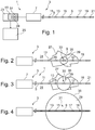
Fig. 1 schematically shows an interventional ablation device according to an embodiment of the present invention. -
Figs. 2 to 4 schematically show a progression of an ablation procedure using an ablation device according to an embodiment of the present invention. -
Figs. 5 to 7 show examples of reflectance spectra measured by an optical sensor as it may be used in an ablation device according to an embodiment of the present invention. - The features shown in the drawings are schematic only and are not to scale. Throughout the figures, similar features are indicated with similar reference signs.
-
Fig. 1 shows aninterventional ablation device 1 according to an embodiment of the present invention. Theablation device 1 may be used for example to ablate, i.e. remove or destroy, e.g. malicious tissue such as tumorous tissue enclosed by healthy tissue. - The
ablation device 1 comprises anablation needle 3 having anelongated body 5 and ahandle 7. Theelongated body 5 has a small diameter of e.g. between 22 and 11 gauge i.e. 0.72 and 3.05 mm and a length of e.g. between 100 and 300 mm or even more preferred between 120 and 250 mm. Furthermore, theelongated body 5 has a pointed tip at a distal end thereof thereby enabling to introduce the ablation needle easily into a patient's tissue. - An
ablation element 9 is arranged on thebody 5. Theablation element 5 is arranged in a region close to the distal end of thebody 5 but spaced apart from this distal end. For example, the ablation element may be arranged at a distance between 5 and 100 mm away from the distal end of thebody 5. - At opposite sides along the
body 5, a plurality ofsensors body 5. The sensors are spaced apart from each other and from theablation element 9 at distances of e.g. between 1 and 50 mm or even more preferred between 1 and 10 mm. - The
ablation needle 3 may be provided as a disposable product. Such disposable needle may be connected to further components of the ablation device. For example, theneedle 3 may be connected to acontroller console 23 which may acquire measurement values from the sensors provided on the needle and may control the ablation element provided on the needle. The needle may be disposed and replaced after each operation. - The
ablation element 9 may be a radio frequency ablation (RFA) element adapted to emit energy by producing a high frequency alternating current in a range of 100 kHz to 500 kHz. Such high frequency energy may be absorbed by ions comprised in the adjacent tissue and due to an agitation of these ions, the tissue may be effectively heated. The heat may induce cell death. Accordingly, when the ablation needle is inserted into a patient's tissue such that itsablation element 9 is located within tumorous tissue, such tumorous tissue may be locally heated and the tumor cells may be destroyed. - Alternatively, the ablation element may rely on other ablation principles such as e.g. cryoablation. In cryoablation, adjacent tissue is cooled down and tumor cells may be killed by icing.
- As schematically shown in the sequence of
Figs. 2 to 4 , theablation needle 3 may be inserted intotumorous tissue 27 enclosed by normalhealthy tissue 31 such that theablation element 9 is located approximately in the center of thetumorous tissue 27. A correct positioning of theablation needle 3 may be monitored e.g. using external imaging means such as ultrasound imaging or computer tomography. After starting an ablation procedure, theablation element 9 heats or cools adjacent tissue within anablation site 31. Theablation volume 35 includingablated tissue 29 around anablation site 33 in which biological cells have been killed due to excessive heat or icing grows with continuing ablation progress. - Conventionally, a surgeon has not been able to monitor the progress of the ablation, i.e. to monitor whether the lesion generated during the ablation procedure has already destroyed the entire tumor or not and whether healthy tissue is started to be damaged. As the heat/icing propagation is difficult to predict because it typically depends strongly of the morphology of the adjacent tissue and whether for instance blood vessels are present, the surgeon had to rely on his experience and frequently not the entire tumor has been destroyed or, on the other side, excessive healthy tissue has been damaged during an ablation procedure.
- In order to overcome such deficiencies, the
ablation device 1 proposed herein comprises a multiplicity ofsensors elongated body 5 on both sides of theablation element 9. Each of the sensors 11-21 may measure parameter values which may be used to indicate physiological information concerningadjacent tissue healthy tissue 31,tumorous tissue 27 orablated tissue 29. - For this purpose, the sensors 11-21 may be provided as optical sensors adapted for measuring a reflectance spectrum of light reflected by the adjacent tissue. The optical sensor may comprise an optical fiber (not shown in the figures for clarity reasons). A distal end of the optical fiber may be arranged at the distal end of the
body 5 thus forming a local sensor 11 - 21. A proximal end of the optical fiber may be connected to acontrol console 23. In theconsole 23, alight source 37 such as an LED and alight detector 39 may be provided. Light coming from thelight source 37 may be coupled into the optical fiber at the proximal end and may propagate towards the distal end where it exits the optical fiber and may illuminate adjacent tissue. Light that is back-reflected towards this fiber may then be captured by the fiber and guided to thedetector 39 at the fiber proximal end. Using such system comprising alight source 37, optical fiber and alight detector 39, the reflectance spectrum may be acquired. Particularly, the reflectance spectrum may be measured in the visible and/or near infrared range. -
Figs. 5 to 7 show reflectance spectra as they may be detected by the detector comprised in one of the sensors 11-21. Such spectra as acquired with reflectance spectroscopy may have typical characteristics depending on the type oftissue Fig. 5 indicates normalhealthy liver tissue 31. The reflectance spectrum shown inFig. 6 representstumorous liver tissue 27. The reflectance spectrum shown inFig. 7 represents ablatedliver tissue 29. Accordingly, from the measurements provided by the sensors 11-21 and the reflectance spectra obtained therewith, physiological information of tissue surrounding anablation side 33 may be derived. - Coming back to
Figs. 2 to 4 , an ablation control scheme may be explained. At the beginning of the ablation process, theRF ablation element 9 is provided with electrical energy which is then transformed to RF energy heating avolume 35 around theablation site 33 adjacent to theablation element 9. At that point in time, none of the sensors 11-21 arranged equidistant along thebody 5 at both sides of theablation element 9 detects ablatedtissue 29. Thesensors ablation element 9 are lying within the tumor and therefore detect a reflectance spectrum representingtumorous tissue 27. Thesensors ablation element 9 are positioned outside the tumor and therefore detect a reflectance spectrum indicating normalhealthy tissue 31. - With progressing ablation process, the
volume 35 of theablation site 33 increases. As shown inFig. 3 , theablated volume 35 reaches theinnermost sensor outer sensors Fig. 4 , theablated volume 35 has also reached thesensors sensors healthy tissue 31 and now measure a reflectance spectrum indicatingablated tissue 29. Based on such monitoring result, the ablation device may detect that theablated volume 29 covers the entire tumor and that the ablation process may be stopped. Such information may either be indicated to a surgeon via adisplay 25 connected to theconsole 23 of theinterventional ablation device 1 or may be used internally in theconsole 23 in order to automatically stop an energy supply to theablation element 9 thereby stopping the ablation process. - In the above described embodiment, physiological information is acquired along a one-dimensional cross-section of the tumor using the sensors 11-21 arranged along the
body 5 of theablation device 1. Since the tumor may be irregular, i.e. larger in a direction perpendicular to the longitudinal direction of theelongated body 5, it may be advantageous to combine the information provided by theablation device 1 with pre-operative data acquired prior to the insertion of the ablation device by using other imaging modalities such as e.g. CT or MRI. From such pre-operative data, the dimension of the tumor in various directions may be deduced. The information that the tumor is smaller in a direction parallel to the longitudinal direction of the insertedelongated body 5 than in a direction perpendicular thereto may be used to correct or adapt the controlling of the ablation procedure. As the dimension of theelongated body 5 and the position of the sensors 11-21 relative to theablation element 9 are known, the size of the tumor along theelongated body 5 may be measured. Using the size perpendicular to the body's 5 longitudinal direction coming from the pre-operative data, the ablation process may be suitably controlled and stopped as soon as theablated volume 29 has reached a size that is larger than the largest dimension of the tumor. - According to a further embodiment, the
ablation device 1 further comprises animaging device 41 possibly comprised in theconsole 23. During an ablation process, theablation needle 3 may be rotated about a longitudinal axis of thebody 5. Thereby, although the sensors 11-21 are positioned only along one dimension and each of the sensors is adapted to acquire a measurement value at one adjacent point in space only, a two-dimensional imaging may be enabled by acquiring a plurality of measurement values using the sensors when arranged in different orientations. Accordingly, a 2D image containing physiological information on adjacent tissue may be acquired from measurement values of the rotated sensors 11-21. Using tomographic algorithms such as e.g. those that have been developed for diffuse optical tomography (DOT), even three-dimensional imaging may be possible by acquiring a plurality of 2D images generated at different locations of the sensors 11-21. - Finally, it is to be noted that instead of or additional to measuring reflectance spectra, the sensors 11-21 may be adapted for measuring other parameters indicative of physiological information using for example fluorescence detection, two-photon spectroscopy, Raman spectroscopy, differential path length spectroscopy or diffuse optical tomography. Furthermore, sensors may be capable of microscopic sensing like using fiber bundle approach, scanning optical coherence tomography or scanning fiber technology. Furthermore, apart from optical sensors, also other sensors like temperature sensors, PH sensors, stiffness sensors or ultrasound transducers may be arranged along the
elongated body 5 of theablation device 1 in order to complement the optical sensors 11-21. The ultrasound technique can be combined with optical methods like photoacoustic detection. - It should be noted that the term "comprising" and similar does not exclude other elements or steps and that the indefinite article "a" does not exclude a plurality of items. Also elements described in association with different embodiments may be combined. It should be furthermore noted that reference signs in the claims shall not be construed as limiting the scope of the claims.
-
- 1
- Ablation device
- 3
- Ablation needle
- 5
- Elongated body
- 7
- Handle
- 9
- Ablation element
- 11
- Sensor
- 13
- Sensor
- 15
- Sensor
- 17
- Sensor
- 19
- Sensor
- 21
- Sensor
- 23
- Console
- 25
- Display
- 27
- Tumorous tissue
- 29
- Ablated tissue
- 31
- Normal tissue
- 33
- Ablation volume
- 35
- Ablation site
- 37
- light source
- 39
- light detector
- 41
- imaging device
Claims (13)
- An interventional ablation needle usable for an ablation device, the needle (3) comprising an elongated body (5) having a distal end, an ablation element (9) arranged in a region close to the distal end of the body (5) and spaced apart from the distal end, and at least two optical sensors (11, 13, 15, 17, 19, 21) arranged on the body (5) adjacent to, and spaced apart from, the ablation element (9) and at opposing sides of the ablation element (9) along a line parallel to the longitudinal axis of the elongated body (5), the optical sensors being adapted for providing measurement values enabling a detecting of physiological information of tissue (27, 29, 31) surrounding an ablation site (33).
- An interventional ablation device (1), comprising:an interventional ablation needle (3) according to claim 1,wherein the device (1) is adapted for detecting physiological information of tissue (27, 29, 31) surrounding an ablation site (33) based on measurement values provided by the sensors (11, 13, 15, 17, 19, 21).
- The device of claim 2, wherein the sensors (11, 13, 15, 17, 19, 21) are connected to a light source (37) and a light detector (39) and wherein the sensors (11, 13, 15, 17, 19, 21) are adapted for providing measurement values based on light reflected by the tissue (27, 29, 31).
- The device of claim 2, wherein the device (1) is adapted for measuring a reflectance spectrum of the light reflected by the tissue (27, 29, 31).
- The device of claim 2, wherein the device (1) is adapted for at least one of fluorescence detection, two-photon spectroscopy, Raman spectroscopy, differential path length spectroscopy, diffuse optical tomography and microscopic sensing.
- The device of claim 2, additionally comprising at least one of a temperature sensor, a PH-sensor, a stiffness sensor and an ultrasound sensor.
- The device of claim 2, wherein the device comprises a controller console (23) for controlling the ablation element (9) based on the detected physiological information.
- The device of claim 7, wherein the controller console (23) is further adapted to control the ablation element (9) taking into account additional information on tissue at the ablation site obtained in pre-operative data acquisition.
- The device of claim 2, wherein the device comprises an imaging device (41) for acquiring a plurality of measurement values provided by a sensor in different orientations of the sensor and generating a 2D image from the acquired measurement values.
- The device of claim 9, wherein the imaging device (41) is adapted to generate a 3D image from a plurality of 2D images generated at different locations of the sensor.
- A computer program element enabling, when executed on a computer, to control the following processes during an ablation procedure:acquiring measurement values provided by a sensor (11, 13, 15, 17, 19, 21) arranged on an elongated body (5) of an interventional ablation needle (3) according to claim 1;providing physiological information of tissue (27, 29, 31) surrounding an ablation site (33) based on the acquired measurement values.
- The computer program element of claim 11, wherein the controlled processes further comprises:- controlling an ablation element (9) provided on the body (5) based on the physiological information.
- A computer readable medium with a computer program element according to claim 12.
Priority Applications (1)
| Application Number | Priority Date | Filing Date | Title |
|---|---|---|---|
| EP11714405.5A EP2538863B1 (en) | 2010-02-26 | 2011-02-22 | Interventional ablation device with tissue discriminating capability |
Applications Claiming Priority (3)
| Application Number | Priority Date | Filing Date | Title |
|---|---|---|---|
| EP10154770 | 2010-02-26 | ||
| PCT/IB2011/050727 WO2011104664A1 (en) | 2010-02-26 | 2011-02-22 | Interventional ablation device with tissue discriminating capability |
| EP11714405.5A EP2538863B1 (en) | 2010-02-26 | 2011-02-22 | Interventional ablation device with tissue discriminating capability |
Publications (2)
| Publication Number | Publication Date |
|---|---|
| EP2538863A1 EP2538863A1 (en) | 2013-01-02 |
| EP2538863B1 true EP2538863B1 (en) | 2019-07-03 |
Family
ID=44306976
Family Applications (1)
| Application Number | Title | Priority Date | Filing Date |
|---|---|---|---|
| EP11714405.5A Active EP2538863B1 (en) | 2010-02-26 | 2011-02-22 | Interventional ablation device with tissue discriminating capability |
Country Status (6)
| Country | Link |
|---|---|
| US (2) | US20120316558A1 (en) |
| EP (1) | EP2538863B1 (en) |
| JP (1) | JP6045916B2 (en) |
| CN (1) | CN102781357B (en) |
| RU (1) | RU2012140962A (en) |
| WO (1) | WO2011104664A1 (en) |
Families Citing this family (14)
| Publication number | Priority date | Publication date | Assignee | Title |
|---|---|---|---|---|
| EP2470100B1 (en) * | 2009-08-27 | 2017-09-20 | New Jersey Institute of Technology | Integrated fiber optic raman spectroscopy and radio frequency ablation |
| JP5807386B2 (en) * | 2011-05-24 | 2015-11-10 | 住友電気工業株式会社 | Biological tissue degeneration equipment |
| US9861427B2 (en) | 2012-01-20 | 2018-01-09 | Koninklijke Philips N.V. | Electro-surgical system, an electro-surgical device, and a method for operating an electro-surgical system |
| EP2950734B1 (en) * | 2013-01-31 | 2019-05-08 | Renal Dynamics Ltd. | Unipolar and/or bipolar ablation catheter |
| EP3003177B1 (en) | 2013-05-31 | 2021-03-10 | Covidien LP | Surgical device with an end-effector assembly for monitoring of tissue during a surgical procedure |
| EP2818127B1 (en) * | 2013-06-20 | 2016-03-16 | Erbe Elektromedizin GmbH | Electrosurgical instrument with light guide |
| JP6396573B2 (en) * | 2014-07-16 | 2018-09-26 | コーニンクレッカ フィリップス エヌ ヴェKoninklijke Philips N.V. | Ultrasonic tracking device for disposable biopsy needles |
| US20160051221A1 (en) * | 2014-08-25 | 2016-02-25 | Covidien Lp | System and Method for Planning, Monitoring, and Confirming Treatment |
| CN107645927B (en) * | 2015-02-17 | 2021-10-08 | 皇家飞利浦有限公司 | Apparatus and method for assisting tissue ablation |
| JP6842431B2 (en) * | 2015-06-10 | 2021-03-17 | ボストン サイエンティフィック サイムド,インコーポレイテッドBoston Scientific Scimed,Inc. | Detection of substances in the body by evaluating the photoluminescent response to excited radiation |
| KR101714310B1 (en) * | 2016-04-01 | 2017-03-08 | 하효은 | Smart electrosurgical unit capable of tracking tumors |
| US10478254B2 (en) | 2016-05-16 | 2019-11-19 | Covidien Lp | System and method to access lung tissue |
| US11219489B2 (en) | 2017-10-31 | 2022-01-11 | Covidien Lp | Devices and systems for providing sensors in parallel with medical tools |
| US11633224B2 (en) | 2020-02-10 | 2023-04-25 | Icecure Medical Ltd. | Cryogen pump |
Citations (1)
| Publication number | Priority date | Publication date | Assignee | Title |
|---|---|---|---|---|
| US6511478B1 (en) * | 2000-06-30 | 2003-01-28 | Scimed Life Systems, Inc. | Medical probe with reduced number of temperature sensor wires |
Family Cites Families (17)
| Publication number | Priority date | Publication date | Assignee | Title |
|---|---|---|---|---|
| US5728143A (en) * | 1995-08-15 | 1998-03-17 | Rita Medical Systems, Inc. | Multiple antenna ablation apparatus and method |
| JPH10243947A (en) * | 1997-03-04 | 1998-09-14 | Olympus Optical Co Ltd | High-frequency device |
| US6558378B2 (en) * | 1998-05-05 | 2003-05-06 | Cardiac Pacemakers, Inc. | RF ablation system and method having automatic temperature control |
| US6251107B1 (en) * | 1998-06-25 | 2001-06-26 | Cardima, Inc. | Ep catheter |
| US20050234437A1 (en) * | 1999-07-14 | 2005-10-20 | Cardiofocus, Inc. | Deflectable sheath catheters with out-of-plane bent tip |
| JP2001037775A (en) * | 1999-07-26 | 2001-02-13 | Olympus Optical Co Ltd | Treatment device |
| EP1272117A2 (en) * | 2000-03-31 | 2003-01-08 | Rita Medical Systems, Inc. | Tissue biopsy and treatment apparatus and method |
| US7520877B2 (en) * | 2000-06-07 | 2009-04-21 | Wisconsin Alumni Research Foundation | Radiofrequency ablation system using multiple prong probes |
| EP1363700A4 (en) * | 2001-01-11 | 2005-11-09 | Rita Medical Systems Inc | Bone-treatment instrument and method |
| US6666862B2 (en) * | 2001-03-01 | 2003-12-23 | Cardiac Pacemakers, Inc. | Radio frequency ablation system and method linking energy delivery with fluid flow |
| WO2004028353A2 (en) * | 2002-09-30 | 2004-04-08 | Vanderbilt University | Optical apparatus for guided liver tumor treatment and methods |
| US7258690B2 (en) * | 2003-03-28 | 2007-08-21 | Relievant Medsystems, Inc. | Windowed thermal ablation probe |
| CN101505672B (en) | 2006-08-22 | 2012-02-08 | 皇家飞利浦电子股份有限公司 | Interventional device for RF ablation for use in RF fields |
| US20080119846A1 (en) * | 2006-10-11 | 2008-05-22 | Rioux Robert F | Methods and apparatus for percutaneous patient access and subcutaneous tissue tunneling |
| EP2142129A4 (en) * | 2007-04-19 | 2011-04-20 | Miramar Labs Inc | Methods and apparatus for reducing sweat production |
| CN102131458B (en) * | 2008-08-22 | 2014-06-11 | 皇家飞利浦电子股份有限公司 | Sensing apparatus for sensing an object |
| WO2011044248A2 (en) * | 2009-10-06 | 2011-04-14 | Cardiofocus, Inc. | Cardiac ablation image analysis system and process |
-
2011
- 2011-02-22 WO PCT/IB2011/050727 patent/WO2011104664A1/en active Application Filing
- 2011-02-22 JP JP2012554457A patent/JP6045916B2/en active Active
- 2011-02-22 EP EP11714405.5A patent/EP2538863B1/en active Active
- 2011-02-22 US US13/578,883 patent/US20120316558A1/en not_active Abandoned
- 2011-02-22 CN CN201180010637.3A patent/CN102781357B/en active Active
- 2011-02-22 RU RU2012140962/14A patent/RU2012140962A/en not_active Application Discontinuation
-
2019
- 2019-02-22 US US16/282,349 patent/US20190183566A1/en not_active Abandoned
Patent Citations (1)
| Publication number | Priority date | Publication date | Assignee | Title |
|---|---|---|---|---|
| US6511478B1 (en) * | 2000-06-30 | 2003-01-28 | Scimed Life Systems, Inc. | Medical probe with reduced number of temperature sensor wires |
Also Published As
| Publication number | Publication date |
|---|---|
| US20120316558A1 (en) | 2012-12-13 |
| JP6045916B2 (en) | 2016-12-14 |
| CN102781357B (en) | 2016-08-03 |
| CN102781357A (en) | 2012-11-14 |
| EP2538863A1 (en) | 2013-01-02 |
| WO2011104664A1 (en) | 2011-09-01 |
| JP2013520269A (en) | 2013-06-06 |
| US20190183566A1 (en) | 2019-06-20 |
| RU2012140962A (en) | 2014-04-10 |
Similar Documents
| Publication | Publication Date | Title |
|---|---|---|
| US20190183566A1 (en) | Interventional ablation device with tissue discriminating capability | |
| EP3551031B1 (en) | System and method for distributed heat flux sensing of body tissue | |
| US10188462B2 (en) | Image-guided therapy of a tissue | |
| JP5701615B2 (en) | Biopsy guidance with electromagnetic tracking and light needle | |
| EP2717029B1 (en) | Heat-sensitive optical probes | |
| US7171253B2 (en) | Apparatus and method for delivering ablative laser energy and determining the volume of tumor mass destroyed | |
| JP5587798B2 (en) | Image-based X-ray guidance system and biopsy guidance with a light needle | |
| US20080228072A1 (en) | Foreign Body Identifier | |
| EP2741696B1 (en) | Displacement feedback device for therapy delivery probes | |
| JP2005199072A (en) | Prediction and assessment of ablation of cardiac tissue | |
| WO1998027865A1 (en) | Device and method for classification of tissue | |
| AU2002303314A1 (en) | Apparatus and method for delivering ablative laser energy and determining the volume of tumor mass destroyed | |
| US10687895B2 (en) | Integrated fiber optic probe for performing image-guided laser induced thermal therapy | |
| JP5611754B2 (en) | Surgery support system | |
| Geoghegan et al. | Interstitial optical monitoring of focal laser ablation | |
| JP5882071B2 (en) | Ultrasound treatment support system | |
| DK200800139U3 (en) | Apparatus for providing ablative laser energy and determining the volume of destroyed tumor mass |
Legal Events
| Date | Code | Title | Description |
|---|---|---|---|
| PUAI | Public reference made under article 153(3) epc to a published international application that has entered the european phase |
Free format text: ORIGINAL CODE: 0009012 |
|
| 17P | Request for examination filed |
Effective date: 20120926 |
|
| AK | Designated contracting states |
Kind code of ref document: A1 Designated state(s): AL AT BE BG CH CY CZ DE DK EE ES FI FR GB GR HR HU IE IS IT LI LT LU LV MC MK MT NL NO PL PT RO RS SE SI SK SM TR |
|
| DAX | Request for extension of the european patent (deleted) | ||
| RAP1 | Party data changed (applicant data changed or rights of an application transferred) |
Owner name: KONINKLIJKE PHILIPS N.V. |
|
| STAA | Information on the status of an ep patent application or granted ep patent |
Free format text: STATUS: EXAMINATION IS IN PROGRESS |
|
| 17Q | First examination report despatched |
Effective date: 20171207 |
|
| GRAP | Despatch of communication of intention to grant a patent |
Free format text: ORIGINAL CODE: EPIDOSNIGR1 |
|
| STAA | Information on the status of an ep patent application or granted ep patent |
Free format text: STATUS: GRANT OF PATENT IS INTENDED |
|
| RIC1 | Information provided on ipc code assigned before grant |
Ipc: A61B 17/00 20060101ALI20181219BHEP Ipc: A61B 34/20 20160101ALI20181219BHEP Ipc: A61B 8/08 20060101AFI20181219BHEP Ipc: G06F 19/00 20180101ALI20181219BHEP Ipc: A61B 18/02 20060101ALI20181219BHEP Ipc: A61B 18/14 20060101ALI20181219BHEP Ipc: A61B 18/00 20060101ALI20181219BHEP Ipc: A61B 5/00 20060101ALI20181219BHEP Ipc: A61B 90/00 20160101ALI20181219BHEP |
|
| REG | Reference to a national code |
Ref country code: DE Ref legal event code: R079 Ref document number: 602011060178 Country of ref document: DE Free format text: PREVIOUS MAIN CLASS: A61B0018140000 Ipc: A61B0008080000 |
|
| INTG | Intention to grant announced |
Effective date: 20190121 |
|
| RIN1 | Information on inventor provided before grant (corrected) |
Inventor name: NACHABE, RAMI Inventor name: DESJARDINS, ADRIEN, EMMANUEL Inventor name: BIERHOFF, WALTHERUS, CORNELIS, JOZEF Inventor name: HENDRIKS, BERNARDUS, HENDRIKUS, WILHELMUS Inventor name: LUCASSEN, GERHARDUS, WILHELMUS |
|
| RIC1 | Information provided on ipc code assigned before grant |
Ipc: A61B 8/08 20060101AFI20190131BHEP Ipc: A61B 18/00 20060101ALI20190131BHEP Ipc: A61B 18/02 20060101ALI20190131BHEP Ipc: A61B 34/20 20160101ALI20190131BHEP Ipc: A61B 18/14 20060101ALI20190131BHEP Ipc: A61B 90/00 20160101ALI20190131BHEP Ipc: A61B 17/00 20060101ALI20190131BHEP Ipc: A61B 5/00 20060101ALI20190131BHEP |
|
| GRAS | Grant fee paid |
Free format text: ORIGINAL CODE: EPIDOSNIGR3 |
|
| GRAA | (expected) grant |
Free format text: ORIGINAL CODE: 0009210 |
|
| STAA | Information on the status of an ep patent application or granted ep patent |
Free format text: STATUS: THE PATENT HAS BEEN GRANTED |
|
| AK | Designated contracting states |
Kind code of ref document: B1 Designated state(s): AL AT BE BG CH CY CZ DE DK EE ES FI FR GB GR HR HU IE IS IT LI LT LU LV MC MK MT NL NO PL PT RO RS SE SI SK SM TR |
|
| REG | Reference to a national code |
Ref country code: GB Ref legal event code: FG4D |
|
| REG | Reference to a national code |
Ref country code: CH Ref legal event code: EP Ref country code: AT Ref legal event code: REF Ref document number: 1150002 Country of ref document: AT Kind code of ref document: T Effective date: 20190715 |
|
| REG | Reference to a national code |
Ref country code: IE Ref legal event code: FG4D |
|
| REG | Reference to a national code |
Ref country code: DE Ref legal event code: R096 Ref document number: 602011060178 Country of ref document: DE |
|
| REG | Reference to a national code |
Ref country code: NL Ref legal event code: MP Effective date: 20190703 |
|
| REG | Reference to a national code |
Ref country code: LT Ref legal event code: MG4D |
|
| REG | Reference to a national code |
Ref country code: AT Ref legal event code: MK05 Ref document number: 1150002 Country of ref document: AT Kind code of ref document: T Effective date: 20190703 |
|
| PG25 | Lapsed in a contracting state [announced via postgrant information from national office to epo] |
Ref country code: SE Free format text: LAPSE BECAUSE OF FAILURE TO SUBMIT A TRANSLATION OF THE DESCRIPTION OR TO PAY THE FEE WITHIN THE PRESCRIBED TIME-LIMIT Effective date: 20190703 Ref country code: BG Free format text: LAPSE BECAUSE OF FAILURE TO SUBMIT A TRANSLATION OF THE DESCRIPTION OR TO PAY THE FEE WITHIN THE PRESCRIBED TIME-LIMIT Effective date: 20191003 Ref country code: NL Free format text: LAPSE BECAUSE OF FAILURE TO SUBMIT A TRANSLATION OF THE DESCRIPTION OR TO PAY THE FEE WITHIN THE PRESCRIBED TIME-LIMIT Effective date: 20190703 Ref country code: AT Free format text: LAPSE BECAUSE OF FAILURE TO SUBMIT A TRANSLATION OF THE DESCRIPTION OR TO PAY THE FEE WITHIN THE PRESCRIBED TIME-LIMIT Effective date: 20190703 Ref country code: HR Free format text: LAPSE BECAUSE OF FAILURE TO SUBMIT A TRANSLATION OF THE DESCRIPTION OR TO PAY THE FEE WITHIN THE PRESCRIBED TIME-LIMIT Effective date: 20190703 Ref country code: PT Free format text: LAPSE BECAUSE OF FAILURE TO SUBMIT A TRANSLATION OF THE DESCRIPTION OR TO PAY THE FEE WITHIN THE PRESCRIBED TIME-LIMIT Effective date: 20191104 Ref country code: FI Free format text: LAPSE BECAUSE OF FAILURE TO SUBMIT A TRANSLATION OF THE DESCRIPTION OR TO PAY THE FEE WITHIN THE PRESCRIBED TIME-LIMIT Effective date: 20190703 Ref country code: NO Free format text: LAPSE BECAUSE OF FAILURE TO SUBMIT A TRANSLATION OF THE DESCRIPTION OR TO PAY THE FEE WITHIN THE PRESCRIBED TIME-LIMIT Effective date: 20191003 Ref country code: CZ Free format text: LAPSE BECAUSE OF FAILURE TO SUBMIT A TRANSLATION OF THE DESCRIPTION OR TO PAY THE FEE WITHIN THE PRESCRIBED TIME-LIMIT Effective date: 20190703 Ref country code: LT Free format text: LAPSE BECAUSE OF FAILURE TO SUBMIT A TRANSLATION OF THE DESCRIPTION OR TO PAY THE FEE WITHIN THE PRESCRIBED TIME-LIMIT Effective date: 20190703 |
|
| PG25 | Lapsed in a contracting state [announced via postgrant information from national office to epo] |
Ref country code: GR Free format text: LAPSE BECAUSE OF FAILURE TO SUBMIT A TRANSLATION OF THE DESCRIPTION OR TO PAY THE FEE WITHIN THE PRESCRIBED TIME-LIMIT Effective date: 20191004 Ref country code: LV Free format text: LAPSE BECAUSE OF FAILURE TO SUBMIT A TRANSLATION OF THE DESCRIPTION OR TO PAY THE FEE WITHIN THE PRESCRIBED TIME-LIMIT Effective date: 20190703 Ref country code: ES Free format text: LAPSE BECAUSE OF FAILURE TO SUBMIT A TRANSLATION OF THE DESCRIPTION OR TO PAY THE FEE WITHIN THE PRESCRIBED TIME-LIMIT Effective date: 20190703 Ref country code: IS Free format text: LAPSE BECAUSE OF FAILURE TO SUBMIT A TRANSLATION OF THE DESCRIPTION OR TO PAY THE FEE WITHIN THE PRESCRIBED TIME-LIMIT Effective date: 20191103 Ref country code: RS Free format text: LAPSE BECAUSE OF FAILURE TO SUBMIT A TRANSLATION OF THE DESCRIPTION OR TO PAY THE FEE WITHIN THE PRESCRIBED TIME-LIMIT Effective date: 20190703 Ref country code: AL Free format text: LAPSE BECAUSE OF FAILURE TO SUBMIT A TRANSLATION OF THE DESCRIPTION OR TO PAY THE FEE WITHIN THE PRESCRIBED TIME-LIMIT Effective date: 20190703 |
|
| RAP2 | Party data changed (patent owner data changed or rights of a patent transferred) |
Owner name: KONINKLIJKE PHILIPS N.V. |
|
| PG25 | Lapsed in a contracting state [announced via postgrant information from national office to epo] |
Ref country code: TR Free format text: LAPSE BECAUSE OF FAILURE TO SUBMIT A TRANSLATION OF THE DESCRIPTION OR TO PAY THE FEE WITHIN THE PRESCRIBED TIME-LIMIT Effective date: 20190703 |
|
| PG25 | Lapsed in a contracting state [announced via postgrant information from national office to epo] |
Ref country code: PL Free format text: LAPSE BECAUSE OF FAILURE TO SUBMIT A TRANSLATION OF THE DESCRIPTION OR TO PAY THE FEE WITHIN THE PRESCRIBED TIME-LIMIT Effective date: 20190703 Ref country code: DK Free format text: LAPSE BECAUSE OF FAILURE TO SUBMIT A TRANSLATION OF THE DESCRIPTION OR TO PAY THE FEE WITHIN THE PRESCRIBED TIME-LIMIT Effective date: 20190703 Ref country code: IT Free format text: LAPSE BECAUSE OF FAILURE TO SUBMIT A TRANSLATION OF THE DESCRIPTION OR TO PAY THE FEE WITHIN THE PRESCRIBED TIME-LIMIT Effective date: 20190703 Ref country code: RO Free format text: LAPSE BECAUSE OF FAILURE TO SUBMIT A TRANSLATION OF THE DESCRIPTION OR TO PAY THE FEE WITHIN THE PRESCRIBED TIME-LIMIT Effective date: 20190703 Ref country code: EE Free format text: LAPSE BECAUSE OF FAILURE TO SUBMIT A TRANSLATION OF THE DESCRIPTION OR TO PAY THE FEE WITHIN THE PRESCRIBED TIME-LIMIT Effective date: 20190703 |
|
| PG25 | Lapsed in a contracting state [announced via postgrant information from national office to epo] |
Ref country code: SM Free format text: LAPSE BECAUSE OF FAILURE TO SUBMIT A TRANSLATION OF THE DESCRIPTION OR TO PAY THE FEE WITHIN THE PRESCRIBED TIME-LIMIT Effective date: 20190703 Ref country code: IS Free format text: LAPSE BECAUSE OF FAILURE TO SUBMIT A TRANSLATION OF THE DESCRIPTION OR TO PAY THE FEE WITHIN THE PRESCRIBED TIME-LIMIT Effective date: 20200224 Ref country code: SK Free format text: LAPSE BECAUSE OF FAILURE TO SUBMIT A TRANSLATION OF THE DESCRIPTION OR TO PAY THE FEE WITHIN THE PRESCRIBED TIME-LIMIT Effective date: 20190703 |
|
| REG | Reference to a national code |
Ref country code: DE Ref legal event code: R097 Ref document number: 602011060178 Country of ref document: DE |
|
| PLBE | No opposition filed within time limit |
Free format text: ORIGINAL CODE: 0009261 |
|
| STAA | Information on the status of an ep patent application or granted ep patent |
Free format text: STATUS: NO OPPOSITION FILED WITHIN TIME LIMIT |
|
| PG2D | Information on lapse in contracting state deleted |
Ref country code: IS |
|
| 26N | No opposition filed |
Effective date: 20200603 |
|
| PG25 | Lapsed in a contracting state [announced via postgrant information from national office to epo] |
Ref country code: SI Free format text: LAPSE BECAUSE OF FAILURE TO SUBMIT A TRANSLATION OF THE DESCRIPTION OR TO PAY THE FEE WITHIN THE PRESCRIBED TIME-LIMIT Effective date: 20190703 |
|
| REG | Reference to a national code |
Ref country code: CH Ref legal event code: PL |
|
| REG | Reference to a national code |
Ref country code: BE Ref legal event code: MM Effective date: 20200229 |
|
| PG25 | Lapsed in a contracting state [announced via postgrant information from national office to epo] |
Ref country code: MC Free format text: LAPSE BECAUSE OF FAILURE TO SUBMIT A TRANSLATION OF THE DESCRIPTION OR TO PAY THE FEE WITHIN THE PRESCRIBED TIME-LIMIT Effective date: 20190703 Ref country code: LU Free format text: LAPSE BECAUSE OF NON-PAYMENT OF DUE FEES Effective date: 20200222 |
|
| PG25 | Lapsed in a contracting state [announced via postgrant information from national office to epo] |
Ref country code: LI Free format text: LAPSE BECAUSE OF NON-PAYMENT OF DUE FEES Effective date: 20200229 Ref country code: CH Free format text: LAPSE BECAUSE OF NON-PAYMENT OF DUE FEES Effective date: 20200229 |
|
| PG25 | Lapsed in a contracting state [announced via postgrant information from national office to epo] |
Ref country code: IE Free format text: LAPSE BECAUSE OF NON-PAYMENT OF DUE FEES Effective date: 20200222 Ref country code: FR Free format text: LAPSE BECAUSE OF NON-PAYMENT OF DUE FEES Effective date: 20200229 |
|
| PG25 | Lapsed in a contracting state [announced via postgrant information from national office to epo] |
Ref country code: BE Free format text: LAPSE BECAUSE OF NON-PAYMENT OF DUE FEES Effective date: 20200229 |
|
| PG25 | Lapsed in a contracting state [announced via postgrant information from national office to epo] |
Ref country code: MT Free format text: LAPSE BECAUSE OF FAILURE TO SUBMIT A TRANSLATION OF THE DESCRIPTION OR TO PAY THE FEE WITHIN THE PRESCRIBED TIME-LIMIT Effective date: 20190703 Ref country code: CY Free format text: LAPSE BECAUSE OF FAILURE TO SUBMIT A TRANSLATION OF THE DESCRIPTION OR TO PAY THE FEE WITHIN THE PRESCRIBED TIME-LIMIT Effective date: 20190703 |
|
| PG25 | Lapsed in a contracting state [announced via postgrant information from national office to epo] |
Ref country code: MK Free format text: LAPSE BECAUSE OF FAILURE TO SUBMIT A TRANSLATION OF THE DESCRIPTION OR TO PAY THE FEE WITHIN THE PRESCRIBED TIME-LIMIT Effective date: 20190703 |
|
| PGFP | Annual fee paid to national office [announced via postgrant information from national office to epo] |
Ref country code: GB Payment date: 20230214 Year of fee payment: 13 Ref country code: DE Payment date: 20220628 Year of fee payment: 13 |