EP2538524A1 - Rotating electric machine - Google Patents
Rotating electric machine Download PDFInfo
- Publication number
- EP2538524A1 EP2538524A1 EP10846099A EP10846099A EP2538524A1 EP 2538524 A1 EP2538524 A1 EP 2538524A1 EP 10846099 A EP10846099 A EP 10846099A EP 10846099 A EP10846099 A EP 10846099A EP 2538524 A1 EP2538524 A1 EP 2538524A1
- Authority
- EP
- European Patent Office
- Prior art keywords
- region
- cylindrical ring
- external cylindrical
- casing
- stator core
- Prior art date
- Legal status (The legal status is an assumption and is not a legal conclusion. Google has not performed a legal analysis and makes no representation as to the accuracy of the status listed.)
- Withdrawn
Links
- 230000003247 decreasing effect Effects 0.000 claims description 6
- 230000000694 effects Effects 0.000 description 8
- 238000004519 manufacturing process Methods 0.000 description 5
- XEEYBQQBJWHFJM-UHFFFAOYSA-N Iron Chemical compound [Fe] XEEYBQQBJWHFJM-UHFFFAOYSA-N 0.000 description 4
- 238000000034 method Methods 0.000 description 3
- 229910000640 Fe alloy Inorganic materials 0.000 description 2
- 229910052742 iron Inorganic materials 0.000 description 2
- 238000004804 winding Methods 0.000 description 2
- 238000001816 cooling Methods 0.000 description 1
- 238000010438 heat treatment Methods 0.000 description 1
- 239000000463 material Substances 0.000 description 1
- 238000012986 modification Methods 0.000 description 1
- 230000004048 modification Effects 0.000 description 1
- 238000000465 moulding Methods 0.000 description 1
- 230000001172 regenerating effect Effects 0.000 description 1
- 239000011347 resin Substances 0.000 description 1
- 229920005989 resin Polymers 0.000 description 1
- 238000007789 sealing Methods 0.000 description 1
Images



Classifications
-
- H—ELECTRICITY
- H02—GENERATION; CONVERSION OR DISTRIBUTION OF ELECTRIC POWER
- H02K—DYNAMO-ELECTRIC MACHINES
- H02K1/00—Details of the magnetic circuit
- H02K1/06—Details of the magnetic circuit characterised by the shape, form or construction
- H02K1/12—Stationary parts of the magnetic circuit
- H02K1/18—Means for mounting or fastening magnetic stationary parts on to, or to, the stator structures
- H02K1/185—Means for mounting or fastening magnetic stationary parts on to, or to, the stator structures to outer stators
Definitions
- the present invention relates to the structure of a rotating electric machine.
- a motor or a generator as a rotating electric machine mounted on a vehicle such as cars includes a rotor, and a stator in an annular shape arranged annularly around the rotor. With the motor, torque is obtained when a current passes through the stator, while with the generator, a current is obtained when the rotor rotates.
- a stator includes an annular stator core having stator winding.
- the stator core has a plurality of annularly arranged divided cores, with an external cylindrical ring being fastened to an outer circumferential surface of the stator core.
- the external cylindrical ring will be deformed due to heating and cooling if shrink fit is employed.
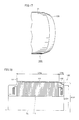
- Fig. 20 is a perspective view of an external cylindrical ring 120.
- External cylindrical ring 120 has a cylindrical shape with open opposite ends, with a flange 122 extending radially outward being provided along the entire circumference of one of the ends.
- Flange 122 includes wide regions 123 each having a bolt hole 123h for use when fixing external cylindrical ring 120 to a motor case, and an alignment hole 123p into which an alignment pin fits if the alignment pin is provided on the motor case as an alignment mechanism.
- the alignment holes may be provided in the motor case and the alignment pins may be provided on the external cylindrical ring as an alignment mechanism.
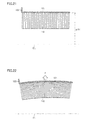
- Fig. 21 is a schematic cross-sectional view showing a state where divided cores 110 have been fixed using external cylindrical ring 120 by shrink fit. If external cylindrical ring 120 is not deformed, external cylindrical ring 120 is completed with an inner diameter ( ⁇ D1) as was designed, and the alignment mechanism (not shown) using alignment holes 123p and the like provided on flange 122 of external cylindrical ring 120 is also completed with designed dimensions.
- ⁇ D1 inner diameter
- ⁇ D1 inner diameter
- the alignment mechanism (not shown) using alignment holes 123p and the like provided on flange 122 of external cylindrical ring 120 is also completed with designed dimensions.
- external cylindrical ring 120 contracts when cooled, causing a high internal pressure (direction of an arrow F in the figure) to be applied from a stator core 111 to an inner surface of external cylindrical ring 120. External cylindrical ring 120 is thus deformed. The amount of deformation is greater on the side of external cylindrical ring 120 where flange 122 is not provided, due to its lower rigidity.
- An alignment mechanism may be provided after an external cylindrical ring is fastened to a stator core. This requires additional work and additional members, however, causing an increase in manufacturing cost of a rotating electric machine.
- a stator having a structure in which annularly arranged divided cores are fastened using an external cylindrical ring is disclosed in the following patent literature.
- a problem to be solved by the present invention is that, when an external cylindrical ring is fastened to a stator core during the manufacture of a stator for use in a rotating electric machine, radial misalignment occurs in an alignment mechanism provided on the stator.
- the present invention was made to solve this problem, and an object of the present invention is to provide a rotating electric machine having a structure capable of suppressing the deformation of an external cylindrical ring when the external cylindrical ring is fastened to a stator core.
- a rotating electric machine based on the present invention includes a stator in an annular shape and a casing for fixing the stator, and has a structure described below.
- the stator includes a stator core, and an external cylindrical ring fastened to an outer circumferential surface of the stator core, and the external cylindrical ring includes a cylindrical body portion, and a flange extending radially outward and being provided on one end portion of the body portion located at an entry side of the casing.
- the body portion includes a fastening region making internal contact with the outer circumferential surface of the stator core and fastened to the outer circumferential surface of the stator core, and a skirt region located at a bottom surface side of the casing and provided with an inner diameter different from an inner diameter of the fastening region, and the skirt region includes a region contacting an inner surface of the casing.
- the skirt region includes a region in which a tip portion at the bottom surface side of the casing is positioned on an outer side relative to the position of the inner diameter of the fastening region.
- the skirt region includes a region provided parallel to the fastening region.
- the skirt region includes a region in which the tip portion at the bottom surface side of the casing is positioned on an inner side relative to the position of the inner diameter of the fastening region, and the inner surface of the casing includes a projecting region contacting the skirt region.
- the skirt region includes a region provided parallel to the fastening region.
- the skirt region has a tapered shape with a diameter gradually decreasing inward.
- the skirt region includes a region not contacting the casing, and a weak area is provided in this region.
- a rotating electric machine having a structure capable of suppressing the deformation of an external cylindrical ring when the external cylindrical ring is fastened to a stator core can be provided.
- Fig. 1 schematically shows an example of the structure of a drive unit I having a rotating electric machine in one embodiment of the present invention.
- drive unit I is mounted on a hybrid vehicle, and includes a motor generator 100, a casing 200, a resolver 350, a reduction gear 300, a differential gear 400, a drive shaft receiving unit 500, and a terminal block 600.
- Motor generator 100 is a rotating electric machine having the function of a motor or a generator, and includes a rotation shaft 150 rotatably mounted in casing 200 via bearings 160, a rotor 130 mounted on rotation shaft 150, and a stator 110.
- Rotor 130 includes a rotor core formed of plate-like magnetic bodies such as iron or iron alloy stacked on one another, and permanent magnets embedded in the rotor core.
- the permanent magnets are arranged at substantially regular intervals in the vicinity of an outer circumference of the rotor core.
- Stator 110 includes a ring-shaped stator core 111, a stator coil 112 wound around stator core 111, and a bus bar 113 connected to stator coil 112.
- Bus bar 113 is connected to a PCU (Power Control Unit) 800 via terminal block 600 provided in casing 200 and a power feed cable 800A.
- PCU 800 is connected to a battery 900 via a power feed cable 900A. Battery 900 is thus electrically connected to stator coil 112.
- Stator core 111 has a plurality of annularly arranged divided cores, each divided core being formed of plate-like magnetic bodies such as iron or iron alloy stacked on one another.
- An inner circumferential surface of stator core 111 is provided with a plurality of teeth (not shown), and slots (not shown) as recesses formed between the teeth. The slots are provided to open to the inner circumference of stator core 111.
- an external cylindrical ring (see Fig. 2 ) for fastening the divided cores is provided on an outer circumferential surface of stator core 111.
- Stator coil 112 including a U-phase, a V-phase and a W-phase as three winding phases is wound around the teeth to fit into the slots.
- the U-phase, V-phase and W-phase of stator coil 112 are wound to be circumferentially out of phase from one another.
- Bus bar 113 includes a U-phase, a V-phase and a W-phase corresponding to the U-phase, V-phase and W-phase of stator coil 112, respectively.
- Power feed cable 800A is a three-phase cable including a U-phase cable, a V-phase cable and a W-phase cable.
- the U-phase, V-phase and W-phase of bus bar 113 are connected to the U-phase cable, V-phase cable and W-phase cable of power feed cable 800A, respectively.
- Motive power output from motor generator 100 is transmitted from reduction gear 300 to drive shaft receiving unit 500 via differential gear 400.
- a driving force transmitted to drive shaft receiving unit 500 is transmitted as torque to wheels (not shown) via a drive shaft (not shown), to run the vehicle.
- Motor generator 100 is driven by torque from the wheels via drive shaft receiving unit 500, differential gear 400 and reduction gear 300.
- motor generator 100 acts as a generator. Electric power generated by motor generator 100 is stored in battery 900 via an inverter in PCU 800.
- Resolver 350 includes a resolver rotor 360 and a resolver stator 370.
- Resolver rotor 360 is connected to rotation shaft 150 of motor generator 100.
- Resolver stator 370 includes a resolver stator core 371, and a resolver stator coil 372 wound around this core.
- Resolver 350 detects an angle of rotation of rotor 130 of motor generator 100.
- the detected angle of rotation is transmitted to PCU 800 via a connector 10.
- PCU 800 generates a drive signal for driving motor generator 100 by using the detected angle of rotation of rotor 130 and a torque command value from an external ECU (Electrical Control Unit), and outputs the generated drive signal to motor generator 100.
- ECU Electronic Control Unit
- FIG. 2 is a schematic perspective view showing the structures of stator 110 and casing 200
- Fig. 3 is a perspective view showing the structure of external cylindrical ring 120A
- Fig. 4 is a cross-sectional view taken along line IV-IV in a direction of arrows in Fig. 3
- Fig. 5 is a partial cross-sectional view showing a state where external cylindrical ring 120A has been fastened to the outer circumferential surface of stator core 111
- Fig. 6 is a partial cross-sectional view showing a state where stator 110 has been fixed within casing 200.
- stator 110 is inserted into casing 200 from an entry side 200a of casing 200, to be aligned and fixed accurately with respect to casing 200.
- the rotor mounted on the inner side of stator 110 is not illustrated in Fig. 2 .
- Stator 110 includes stator core 111, and external cylindrical ring 120A to be fastened to the outer circumferential surface of stator core 111.
- external cylindrical ring 120A includes a cylindrical body portion 121, and a flange 122 extending radially outward and being provided on one end portion of body portion 121 located at entry side 200a of casing 200.
- Flange 122 includes wide regions 123 each having a bolt hole 123h for use when fixing external cylindrical ring 120A to casing 200, with a pitch of 120 degrees around a rotation central axis CL.
- body portion 121 includes a fastening region 121 a making internal contact with the outer circumferential surface of stator core 111 to be fastened to the outer circumferential surface of stator core 111, and a skirt region 121b located at a bottom surface side 200b (opposite to the side where flange 122 is provided) of casing 200 and provided with an inner diameter ( ⁇ D2) different from an inner diameter ( ⁇ D1) of fastening region 121 a.
- skirt region 121b is positioned on an outer side relative to the position of the inner diameter of fastening region 121a.
- Skirt region 121b includes a tapered skirt region 125a gradually extending radially outward, and a cylindrical skirt region 125b provided parallel to fastening region 121a.
- the inner diameter ( ⁇ D2) of cylindrical skirt region 125b is set to be larger than the inner diameter ( ⁇ D1) of fastening region 121a.
- skirt region 121b is a member of external cylindrical ring 120A with a diameter increasing outward, thereby achieving increased rigidity of skirt region 121b as with flange 122.
- cylindrical skirt region 125b of external cylindrical ring 120A has a highly accurate outer diameter dimension ( ⁇ R1) after the fastening, thus enabling an outer surface of cylindrical skirt region 125b to abut an inner surface of a cylindrical portion 201 of casing 200.
- stator 110 can be aligned accurately with respect to casing 200.
- stator 110 and casing 200 can be performed using cylindrical skirt region 125b, eliminating the need to adopt a conventional alignment mechanism using a pin or the like. Therefore, a rotating electric machine having high operational reliability can be provided without increasing manufacturing cost of the rotating electric machine.
- FIG. 7 is a partial perspective view showing the structure of an external cylindrical ring 120B
- Fig. 8 is a cross-sectional view taken along line VIII in a direction of an arrow in Fig. 7
- Fig. 9 is a partial perspective view showing the structure of an external cylindrical ring 120C of another embodiment
- Fig. 10 is a partial cross-sectional view showing the structure of an external cylindrical ring 120D of yet another embodiment.
- External cylindrical ring 120B in a second embodiment includes fastening region 121a and skirt region 121b identical in outer shape to those of external cylindrical ring 120A in the first embodiment, and further includes a plurality of openings 125h provided in tapered skirt region 125a of skirt region 121b.
- tapered skirt region 125a By providing the plurality of openings 125h as weak areas in tapered skirt region 125a, tapered skirt region 125a will be readily deformed. By providing openings 125h, stress generated when fastening external cylindrical ring 120B to stator core 111 can be actively absorbed in the weak areas, thereby further enabling the dimensional accuracy of the outer surface of cylindrical skirt region 125b to fall within tolerance.
- a double plurality of openings 125h can be provided annularly as shown in external cylindrical ring 120C of Fig. 9 , or a triple plurality of openings 125h can be provided, for example. Alternatively, openings 125h can be alternately shifted.
- a groove 125g may be provided as a thin portion in tapered skirt region 125a as in external cylindrical ring 120D shown in Fig. 10 .
- Groove 125g may be in a continuous annular shape, or may be divided into a plurality of grooves as with openings 125h.
- FIG. 11 shows the structure of an external cylindrical ring 120E, taken along line XI-XI in a direction of arrows in Fig. 3 .
- External cylindrical ring 120E in a third embodiment includes fastening region 121 a identical in outer shape to that of external cylindrical ring 120A in the first embodiment, and skirt region 121 b divided into three sections instead of being in a continuous annular shape.
- the width of and space between skirt regions 121b is set with a pitch of 60 degrees circumferentially.
- the same function and effect as those of external cylindrical ring 120A in the first embodiment can be obtained.
- the size of a rotating electric machine varies with the required capacity.
- the shape of an external cylindrical ring and the thicknesses of members are selected out of a variety of optimal materials.
- the rigidity of skirt regions 121b can be adjusted.
- weak areas can be actively provided in the tapered skirt regions in this embodiment as well.
- FIG. 12 is a partial perspective view showing the structure of an external cylindrical ring 120F
- Fig. 13 is a partial cross-sectional view showing a state where external cylindrical ring 120F has been fastened to the outer circumferential surface of stator core 111
- Fig. 14 is a partial cross-sectional view showing a state where stator 110 has been fixed within casing 200
- Fig. 15 is a partial cross-sectional view showing an external cylindrical ring 120G of another embodiment
- Fig. 16 is a partial cross-sectional view showing an external cylindrical ring 120H of yet another embodiment.
- external cylindrical ring 120F in this embodiment includes cylindrical body portion 121, and flange 122 extending radially outward and being provided on one end portion of body portion 121 located at entry side 200a of casing 200, which are the same as those of external cylindrical ring 120A in the first embodiment. While not illustrated in Fig. 12 , flange 122 has the same shape as that of flange 122 in the first embodiment.
- body portion 121 includes fastening region 121 a making internal contact with the outer circumferential surface of stator core 111 to be fastened to the outer circumferential surface of stator core 111, and skirt region 121 b located at bottom surface side 200b (opposite to the side where flange 122 is provided) of casing 200 and provided with an inner diameter ( ⁇ D3) different from the inner diameter ( ⁇ D1) of fastening region 121a.
- skirt region 121b is positioned on an inner side relative to the position of the inner diameter of fastening region 121 a.
- Skirt region 121b includes a tapered skirt region 125c with a diameter gradually decreasing radially inward, and a cylindrical skirt region 125d provided parallel to fastening region 121a.
- An inner diameter ( ⁇ D3) of cylindrical skirt region 125d is set to be smaller than the inner diameter ( ⁇ D1) of fastening region 121a.
- stator core 111 When stator core 111 is fastened using external cylindrical ring 120F having the structure described above, the deformation of external cylindrical ring 120F when fastened to stator core 111 can be suppressed. This is because skirt region 121b is a member of external cylindrical ring 120F with a diameter decreasing inward, thereby achieving increased rigidity of skirt region 121b as with flange 122.
- cylindrical skirt region 125d of external cylindrical ring 120F has a highly accurate outer diameter dimension ( ⁇ R2) after the fastening, thus enabling an outer surface of cylindrical skirt region 125b to abut a projecting region 201P provided on the inner surface of cylindrical portion 201 of casing 200.
- ⁇ R2 outer diameter dimension
- stator 110 can be aligned accurately with respect to casing 200.
- Projection region 201 P may be provided annularly on the inner surface of cylindrical portion 201, or may be divided into a plurality of sections.
- stator 110 and casing 200 can be performed using cylindrical skirt region 125d, eliminating the need to adopt a conventional alignment mechanism using a pin or the like. Therefore, a rotating electric machine having high operational reliability can be provided without increasing manufacturing cost of the rotating electric machine.
- tapered skirt region 125c may be provided with the plurality of openings 125h as weak areas (external cylindrical ring 120G shown in Fig. 15 ), or may be provided with groove 125g (external cylindrical ring 120H shown in Fig. 16 ), as was described in the second embodiment.
- FIG. 17 is a partial perspective view showing the structure of an external cylindrical ring 120I
- Fig. 18 is a partial cross-sectional view showing a state where external cylindrical ring 120I has been fastened to the outer circumferential surface of stator core 111
- Fig. 19 is a partial cross-sectional view showing a state where stator 110 has been fixed within the casing.
- external cylindrical ring 120I in this embodiment includes cylindrical body portion 121, and flange 122 extending radially outward and being provided on one end portion of body portion 121 located at entry side 200a of casing 200, which are the same as those of external cylindrical ring 120A in the first embodiment. While not illustrated in Fig. 17 , flange 122 has the same shape as that of flange 122 in the first embodiment.
- body portion 121 includes fastening region 121 a making internal contact with the outer circumferential surface of stator core 111 to be fastened to the outer circumferential surface of stator core 111, and skirt region 121b located at bottom surface side 200b (opposite to the side where flange 122 is provided) of casing 200 and provided with an inner diameter different from the inner diameter ( ⁇ D1) of fastening region 121a.
- skirt region 121b is positioned on an inner side relative to the position of the inner diameter of fastening region 121a.
- Skirt region 121b includes a tapered skirt region 125I with a diameter gradually decreasing radially inward.
- a minimum inner diameter ( ⁇ D4) of tapered skirt region 125I is set to be smaller than the inner diameter ( ⁇ D1) of fastening region 121a.
- stator core 111 is fastened using external cylindrical ring 120I having the structure described above, the deformation of external cylindrical ring 120I when fastened to stator core 111 can be suppressed.
- skirt region 121b is a member of external cylindrical ring 120I with a diameter decreasing inward, thereby achieving increased rigidity of skirt region 121b as with flange 122.
- tapered skirt region 125I of external cylindrical ring 120I has a highly accurate outer diameter dimension ( ⁇ R3) after the fastening, thus enabling an outer surface of tapered skirt region 125I to abut projecting region 201P provided on the inner surface of cylindrical portion 201 of casing 200.
- Projection region 201P may be provided annularly on the inner surface of cylindrical portion 201. or may be divided into a plurality of sections.
- the outer surface of tapered skirt region 125I abutting projecting region 201P has a conical shape, thus facilitating the centering of stator 110.
- stator 110 and casing 200 can be performed using tapered skirt region 125I, eliminating the need to adopt a conventional alignment mechanism using a pin or the like. Therefore, a rotating electric machine having high operational reliability can be provided without increasing manufacturing cost of the rotating electric machine
- I drive unit 100 motor generator (rotating electric machine); 110 stator; 111 stator core; 112 stator coil; 113 bus bar; 120A, 120B, 120C, 120D, 120E, 120F, 120G, 120H, 120I external cylindrical ring; 121 body portion; 121a fastening region; 121b skirt region; 122 flange; 123 wide region; 123h bolt hole; 125a, 125c, 1251 tapered skirt region; 125b, 125d cylindrical skirt region; 125g groove; 125h opening; 130 rotor; 150 rotation shaft; 160 bearing; 200 casing; 200a entry side; 200b bottom surface side; 300 reduction gear; 350 resolver; 370 resolver stator; 371 resolver stator core; 372 resolver stator coil; 400 differential gear; 500 drive shaft receiving unit; 600 terminal block; 800 PCU (Power Control Unit); 800A power feed cable; 900 battery; 900A power feed cable; CL rotation central axis
Landscapes
- Engineering & Computer Science (AREA)
- Power Engineering (AREA)
- Iron Core Of Rotating Electric Machines (AREA)
- Motor Or Generator Frames (AREA)
Abstract
Description
- The present invention relates to the structure of a rotating electric machine.
- A motor or a generator as a rotating electric machine mounted on a vehicle such as cars includes a rotor, and a stator in an annular shape arranged annularly around the rotor. With the motor, torque is obtained when a current passes through the stator, while with the generator, a current is obtained when the rotor rotates.
- A stator includes an annular stator core having stator winding. The stator core has a plurality of annularly arranged divided cores, with an external cylindrical ring being fastened to an outer circumferential surface of the stator core.
- When fixing the stator to a motor case, alignment and centering between the stator and the motor case is usually performed with an alignment mechanism using a pin or the like provided on the external cylindrical ring. When fastening the external cylindrical ring to the annularly arranged divided cores, however, the external cylindrical ring is heated and cooled by shrink fit and molding resin sealing, which may result in radial misalignment of the alignment mechanism using a pin or the like.
- For example, even if the alignment mechanism using a pin or the like is provided between the external cylindrical ring and the motor case with reference to an inner diameter of the external cylindrical ring, the external cylindrical ring will be deformed due to heating and cooling if shrink fit is employed.
-
Fig. 20 is a perspective view of an externalcylindrical ring 120. Externalcylindrical ring 120 has a cylindrical shape with open opposite ends, with aflange 122 extending radially outward being provided along the entire circumference of one of the ends.Flange 122 includeswide regions 123 each having abolt hole 123h for use when fixing externalcylindrical ring 120 to a motor case, and analignment hole 123p into which an alignment pin fits if the alignment pin is provided on the motor case as an alignment mechanism. Alternatively, the alignment holes may be provided in the motor case and the alignment pins may be provided on the external cylindrical ring as an alignment mechanism. -
Fig. 21 is a schematic cross-sectional view showing a state wheredivided cores 110 have been fixed using externalcylindrical ring 120 by shrink fit. If externalcylindrical ring 120 is not deformed, externalcylindrical ring 120 is completed with an inner diameter (φD1) as was designed, and the alignment mechanism (not shown) usingalignment holes 123p and the like provided onflange 122 of externalcylindrical ring 120 is also completed with designed dimensions. - As shown in
Fig. 22 , however, when shrink fit is employed, externalcylindrical ring 120 contracts when cooled, causing a high internal pressure (direction of an arrow F in the figure) to be applied from astator core 111 to an inner surface of externalcylindrical ring 120. Externalcylindrical ring 120 is thus deformed. The amount of deformation is greater on the side of externalcylindrical ring 120 whereflange 122 is not provided, due to its lower rigidity. - Accordingly, external
cylindrical ring 120 is deformed, resulting in misalignment ofalignment holes 123p provided inflange 122. It is noted thatFig. 22 exaggerates the actual amount of deformation to facilitate understanding of the deformation of externalcylindrical ring 120. - An alignment mechanism may be provided after an external cylindrical ring is fastened to a stator core. This requires additional work and additional members, however, causing an increase in manufacturing cost of a rotating electric machine. A stator having a structure in which annularly arranged divided cores are fastened using an external cylindrical ring is disclosed in the following patent literature.
-
- PTL 1: Japanese Patent Laying-Open No.
2005-312151 - A problem to be solved by the present invention is that, when an external cylindrical ring is fastened to a stator core during the manufacture of a stator for use in a rotating electric machine, radial misalignment occurs in an alignment mechanism provided on the stator. The present invention was made to solve this problem, and an object of the present invention is to provide a rotating electric machine having a structure capable of suppressing the deformation of an external cylindrical ring when the external cylindrical ring is fastened to a stator core.
- A rotating electric machine based on the present invention includes a stator in an annular shape and a casing for fixing the stator, and has a structure described below.
- The stator includes a stator core, and an external cylindrical ring fastened to an outer circumferential surface of the stator core, and the external cylindrical ring includes a cylindrical body portion, and a flange extending radially outward and being provided on one end portion of the body portion located at an entry side of the casing.
- The body portion includes a fastening region making internal contact with the outer circumferential surface of the stator core and fastened to the outer circumferential surface of the stator core, and a skirt region located at a bottom surface side of the casing and provided with an inner diameter different from an inner diameter of the fastening region, and the skirt region includes a region contacting an inner surface of the casing.
- In another embodiment of the invention, the skirt region includes a region in which a tip portion at the bottom surface side of the casing is positioned on an outer side relative to the position of the inner diameter of the fastening region.
- In another embodiment, the skirt region includes a region provided parallel to the fastening region.
- In another embodiment, the skirt region includes a region in which the tip portion at the bottom surface side of the casing is positioned on an inner side relative to the position of the inner diameter of the fastening region, and the inner surface of the casing includes a projecting region contacting the skirt region.
- In another embodiment, the skirt region includes a region provided parallel to the fastening region.
- In another embodiment, the skirt region has a tapered shape with a diameter gradually decreasing inward.
- In any one of the other embodiments of the invention, the skirt region includes a region not contacting the casing, and a weak area is provided in this region.
- According to the rotating electric machine based on the present invention, a rotating electric machine having a structure capable of suppressing the deformation of an external cylindrical ring when the external cylindrical ring is fastened to a stator core can be provided.
-
-
Fig. 1 schematically shows an example of the structure of a drive unit having a rotating electric machine in a first embodiment. -
Fig. 2 is a schematic perspective view showing the structures of a stator and a casing of the rotating electric machine in the first embodiment. -
Fig. 3 is a perspective view showing the structure of an external cylindrical ring in the first embodiment. -
Fig. 4 is a cross-sectional view taken along line IV-IV in a direction of arrows inFig. 3 . -
Fig. 5 is a partial cross-sectional view showing a state where the external cylindrical ring has been fastened to an outer circumferential surface of a stator core in the first embodiment. -
Fig. 6 is a partial cross-sectional view showing a state where the stator has been fixed within the casing in the first embodiment. -
Fig. 7 is a partial perspective view showing the structure of an external cylindrical ring in a second embodiment. -
Fig. 8 is a cross-sectional view taken along line VIII in a direction of an arrow inFig. 7 . -
Fig. 9 is a partial perspective view showing another embodiment of the external cylindrical ring in the second embodiment. -
Fig. 10 is a partial cross-sectional view showing yet another embodiment of the external cylindrical ring in the second embodiment. -
Fig. 11 shows the structure of an external cylindrical ring in a third embodiment, taken along line XI-XI in a direction of arrows inFig. 3 . -
Fig. 12 is a partial perspective view showing the structure of an external cylindrical ring in a fourth embodiment. -
Fig. 13 is a partial cross-sectional view showing a state where the external cylindrical ring has been fastened to an outer circumferential surface of a stator core in the fourth embodiment. -
Fig. 14 is a partial cross-sectional view showing a state where a stator has been fixed within a casing in the fourth embodiment. -
Fig. 15 is a partial cross-sectional view showing another embodiment of the external cylindrical ring in the fourth embodiment. -
Fig. 16 is a partial cross-sectional view showing yet another embodiment of the external cylindrical ring in the fourth embodiment. -
Fig. 17 is a partial perspective view showing the structure of an external cylindrical ring in a fifth embodiment. -
Fig. 18 is a partial cross-sectional view showing a state where the external cylindrical ring has been fastened to an outer circumferential surface of a stator core in the fifth embodiment. -
Fig. 19 is a partial cross-sectional view showing a state where a stator has been fixed within a casing in the fifth embodiment. -
Fig. 20 is a perspective view showing the structure of an external cylindrical ring in the background technique. -
Fig. 21 is a partial cross-sectional view showing a state where the external cylindrical ring has been fastened to an outer circumferential surface of a stator core in the background technique. -
Fig. 22 is a view for explaining a problem in the background technique. - Rotating electric machine in embodiments based on the present invention will be described with reference to the drawings. If any reference to a number, an amount and the like is made in the embodiments described below, the scope of the present invention is not necessarily limited to that number, amount and the like unless otherwise specified.
- In the description, the same or corresponding components are designated by the same reference numbers, and redundant description may not be repeated. Furthermore, unless otherwise specified, it is originally intended to appropriately combine structures described in the following embodiments for use.
-
Fig. 1 schematically shows an example of the structure of a drive unit I having a rotating electric machine in one embodiment of the present invention. In the example shown inFig. 1 , drive unit I is mounted on a hybrid vehicle, and includes amotor generator 100, acasing 200, aresolver 350, areduction gear 300, adifferential gear 400, a driveshaft receiving unit 500, and aterminal block 600. -
Motor generator 100 is a rotating electric machine having the function of a motor or a generator, and includes arotation shaft 150 rotatably mounted incasing 200 viabearings 160, arotor 130 mounted onrotation shaft 150, and astator 110. -
Rotor 130 includes a rotor core formed of plate-like magnetic bodies such as iron or iron alloy stacked on one another, and permanent magnets embedded in the rotor core. The permanent magnets are arranged at substantially regular intervals in the vicinity of an outer circumference of the rotor core. -
Stator 110 includes a ring-shapedstator core 111, astator coil 112 wound aroundstator core 111, and abus bar 113 connected tostator coil 112.Bus bar 113 is connected to a PCU (Power Control Unit) 800 viaterminal block 600 provided incasing 200 and apower feed cable 800A.PCU 800 is connected to abattery 900 via apower feed cable 900A.Battery 900 is thus electrically connected tostator coil 112. -
Stator core 111 has a plurality of annularly arranged divided cores, each divided core being formed of plate-like magnetic bodies such as iron or iron alloy stacked on one another. An inner circumferential surface ofstator core 111 is provided with a plurality of teeth (not shown), and slots (not shown) as recesses formed between the teeth. The slots are provided to open to the inner circumference ofstator core 111. On an outer circumferential surface ofstator core 111, an external cylindrical ring (seeFig. 2 ) for fastening the divided cores is provided. -
Stator coil 112 including a U-phase, a V-phase and a W-phase as three winding phases is wound around the teeth to fit into the slots. The U-phase, V-phase and W-phase ofstator coil 112 are wound to be circumferentially out of phase from one another.Bus bar 113 includes a U-phase, a V-phase and a W-phase corresponding to the U-phase, V-phase and W-phase ofstator coil 112, respectively. -
Power feed cable 800A is a three-phase cable including a U-phase cable, a V-phase cable and a W-phase cable. The U-phase, V-phase and W-phase ofbus bar 113 are connected to the U-phase cable, V-phase cable and W-phase cable ofpower feed cable 800A, respectively. - Motive power output from
motor generator 100 is transmitted fromreduction gear 300 to driveshaft receiving unit 500 viadifferential gear 400. A driving force transmitted to driveshaft receiving unit 500 is transmitted as torque to wheels (not shown) via a drive shaft (not shown), to run the vehicle. - During regenerative braking of the hybrid vehicle, on the other hand, the wheels are rotated by an inertial force of a vehicle body.
Motor generator 100 is driven by torque from the wheels via driveshaft receiving unit 500,differential gear 400 andreduction gear 300. Here,motor generator 100 acts as a generator. Electric power generated bymotor generator 100 is stored inbattery 900 via an inverter inPCU 800. -
Resolver 350 includes aresolver rotor 360 and aresolver stator 370.Resolver rotor 360 is connected torotation shaft 150 ofmotor generator 100.Resolver stator 370 includes aresolver stator core 371, and aresolver stator coil 372 wound around this core. -
Resolver 350 detects an angle of rotation ofrotor 130 ofmotor generator 100. The detected angle of rotation is transmitted toPCU 800 via aconnector 10.PCU 800 generates a drive signal for drivingmotor generator 100 by using the detected angle of rotation ofrotor 130 and a torque command value from an external ECU (Electrical Control Unit), and outputs the generated drive signal tomotor generator 100. - Referring now to
Figs. 2 to 6 , the structure of an externalcylindrical ring 120A in this embodiment will be described.Fig. 2 is a schematic perspective view showing the structures ofstator 110 andcasing 200,Fig. 3 is a perspective view showing the structure of externalcylindrical ring 120A,Fig. 4 is a cross-sectional view taken along line IV-IV in a direction of arrows inFig. 3 ,Fig. 5 is a partial cross-sectional view showing a state where externalcylindrical ring 120A has been fastened to the outer circumferential surface ofstator core 111, andFig. 6 is a partial cross-sectional view showing a state wherestator 110 has been fixed withincasing 200. - Referring to
Fig. 2 ,stator 110 is inserted intocasing 200 from anentry side 200a ofcasing 200, to be aligned and fixed accurately with respect tocasing 200. The rotor mounted on the inner side ofstator 110 is not illustrated inFig. 2 .Stator 110 includesstator core 111, and externalcylindrical ring 120A to be fastened to the outer circumferential surface ofstator core 111. - Referring to
Fig. 3 , externalcylindrical ring 120A includes acylindrical body portion 121, and aflange 122 extending radially outward and being provided on one end portion ofbody portion 121 located atentry side 200a ofcasing 200.Flange 122 includeswide regions 123 each having abolt hole 123h for use when fixing externalcylindrical ring 120A tocasing 200, with a pitch of 120 degrees around a rotation central axis CL. - Referring to
Fig. 4 ,body portion 121 includes afastening region 121 a making internal contact with the outer circumferential surface ofstator core 111 to be fastened to the outer circumferential surface ofstator core 111, and askirt region 121b located at abottom surface side 200b (opposite to the side whereflange 122 is provided) ofcasing 200 and provided with an inner diameter (φD2) different from an inner diameter (φD1) offastening region 121 a. - In this embodiment, at least a tip portion of
skirt region 121b is positioned on an outer side relative to the position of the inner diameter offastening region 121a.Skirt region 121b includes a taperedskirt region 125a gradually extending radially outward, and acylindrical skirt region 125b provided parallel tofastening region 121a. The inner diameter (φD2) ofcylindrical skirt region 125b is set to be larger than the inner diameter (φD1) offastening region 121a. - Referring to
Fig. 5 , whenstator core 111 is fastened using externalcylindrical ring 120A having the structure described above, the deformation of externalcylindrical ring 120A when fastened to stator core 111can be suppressed. This is becauseskirt region 121b is a member of externalcylindrical ring 120A with a diameter increasing outward, thereby achieving increased rigidity ofskirt region 121b as withflange 122. - During shrink fit, external
cylindrical ring 120A contracts when cooled, causing a high internal pressure to be applied fromstator core 111 to an inner surface of externalcylindrical ring 120A. Yet the deformation ofskirt region 121b can be suppressed owing to the increased rigidity ofskirt region 121b. - Consequently, as shown in
Fig. 6 ,cylindrical skirt region 125b of externalcylindrical ring 120A has a highly accurate outer diameter dimension (φR1) after the fastening, thus enabling an outer surface ofcylindrical skirt region 125b to abut an inner surface of acylindrical portion 201 ofcasing 200. As a result,stator 110 can be aligned accurately with respect tocasing 200. - As described above, according to this embodiment, when external
cylindrical ring 120A is fastened tostator core 111, the deformation ofskirt region 121b of externalcylindrical ring 120A can be suppressed. As a result, after externalcylindrical ring 120A has been fastened tostator core 111 by shrink fit, the dimensional accuracy of the outer surface ofcylindrical skirt region 125b of externalcylindrical ring 120A can fall within tolerance. - Accordingly, alignment between
stator 110 andcasing 200 can be performed usingcylindrical skirt region 125b, eliminating the need to adopt a conventional alignment mechanism using a pin or the like. Therefore, a rotating electric machine having high operational reliability can be provided without increasing manufacturing cost of the rotating electric machine. - Referring now to
Figs. 7 to 10 , other embodiments of the external cylindrical ring will be described. The structures ofmotor generator 100 andstator core 111 are the same as those in the first embodiment, and thus description thereof will not be repeated.Fig. 7 is a partial perspective view showing the structure of an externalcylindrical ring 120B,Fig. 8 is a cross-sectional view taken along line VIII in a direction of an arrow inFig. 7 ,Fig. 9 is a partial perspective view showing the structure of an externalcylindrical ring 120C of another embodiment, andFig. 10 is a partial cross-sectional view showing the structure of an externalcylindrical ring 120D of yet another embodiment. - External
cylindrical ring 120B in a second embodiment includesfastening region 121a andskirt region 121b identical in outer shape to those of externalcylindrical ring 120A in the first embodiment, and further includes a plurality ofopenings 125h provided in taperedskirt region 125a ofskirt region 121b. - By providing the plurality of
openings 125h as weak areas in taperedskirt region 125a, taperedskirt region 125a will be readily deformed. By providingopenings 125h, stress generated when fastening externalcylindrical ring 120B tostator core 111 can be actively absorbed in the weak areas, thereby further enabling the dimensional accuracy of the outer surface ofcylindrical skirt region 125b to fall within tolerance. - While the single plurality of
openings 125h are provided annularly in taperedskirt region 125a in externalcylindrical ring 120B shown inFig. 8 , a double plurality ofopenings 125h can be provided annularly as shown in externalcylindrical ring 120C ofFig. 9 , or a triple plurality ofopenings 125h can be provided, for example. Alternatively,openings 125h can be alternately shifted. - Furthermore, instead of providing
openings 125h as in externalcylindrical ring 120B and externalcylindrical ring 120C, agroove 125g may be provided as a thin portion in taperedskirt region 125a as in externalcylindrical ring 120D shown inFig. 10 .Groove 125g may be in a continuous annular shape, or may be divided into a plurality of grooves as withopenings 125h. - As described above, according to this embodiment, the same function and effect as those of external
cylindrical ring 120A in the first embodiment can be obtained. Moreover, by actively providing the weak areas in taperedskirt region 125a, stress generated when fastening externalcylindrical ring 120B tostator core 111 can be actively absorbed in the weak areas, thereby further enabling the dimensional accuracy of the outer surface ofcylindrical skirt region 125b to fall within tolerance. - Referring now to
Fig. 11 , another embodiment of the external cylindrical ring will be described. The structures ofmotor generator 100 andstator core 111 are the same as those in the first embodiment, and thus description thereof will not be repeated.Fig. 11 shows the structure of an externalcylindrical ring 120E, taken along line XI-XI in a direction of arrows inFig. 3 . - External
cylindrical ring 120E in a third embodiment includesfastening region 121 a identical in outer shape to that of externalcylindrical ring 120A in the first embodiment, andskirt region 121 b divided into three sections instead of being in a continuous annular shape. In this embodiment, the width of and space betweenskirt regions 121b is set with a pitch of 60 degrees circumferentially. - As described above, according to this embodiment, the same function and effect as those of external
cylindrical ring 120A in the first embodiment can be obtained. The size of a rotating electric machine varies with the required capacity. Thus, the shape of an external cylindrical ring and the thicknesses of members are selected out of a variety of optimal materials. By dividingskirt region 121b into a plurality of sections, therefore, the rigidity ofskirt regions 121b can be adjusted. As was described in the second embodiment, weak areas can be actively provided in the tapered skirt regions in this embodiment as well. - Referring now to
Figs. 12 to 16 , another embodiment of the external cylindrical ring will be described. The structures ofmotor generator 100 andstator core 111 are the same as those in the first embodiment, and thus description thereof will not be repeated.Fig. 12 is a partial perspective view showing the structure of an externalcylindrical ring 120F,Fig. 13 is a partial cross-sectional view showing a state where externalcylindrical ring 120F has been fastened to the outer circumferential surface ofstator core 111,Fig. 14 is a partial cross-sectional view showing a state wherestator 110 has been fixed withincasing 200,Fig. 15 is a partial cross-sectional view showing an externalcylindrical ring 120G of another embodiment, andFig. 16 is a partial cross-sectional view showing an externalcylindrical ring 120H of yet another embodiment. - Referring to
Fig. 12 , externalcylindrical ring 120F in this embodiment includescylindrical body portion 121, andflange 122 extending radially outward and being provided on one end portion ofbody portion 121 located atentry side 200a ofcasing 200, which are the same as those of externalcylindrical ring 120A in the first embodiment. While not illustrated inFig. 12 ,flange 122 has the same shape as that offlange 122 in the first embodiment. - Referring to
Fig. 13 ,body portion 121 includesfastening region 121 a making internal contact with the outer circumferential surface ofstator core 111 to be fastened to the outer circumferential surface ofstator core 111, andskirt region 121 b located atbottom surface side 200b (opposite to the side whereflange 122 is provided) ofcasing 200 and provided with an inner diameter (φD3) different from the inner diameter (φD1) offastening region 121a. - In this embodiment, at least a tip portion of
skirt region 121b is positioned on an inner side relative to the position of the inner diameter offastening region 121 a.Skirt region 121b includes a taperedskirt region 125c with a diameter gradually decreasing radially inward, and acylindrical skirt region 125d provided parallel tofastening region 121a. An inner diameter (φD3) ofcylindrical skirt region 125d is set to be smaller than the inner diameter (φD1) offastening region 121a. - When
stator core 111 is fastened using externalcylindrical ring 120F having the structure described above, the deformation of externalcylindrical ring 120F when fastened tostator core 111 can be suppressed. This is becauseskirt region 121b is a member of externalcylindrical ring 120F with a diameter decreasing inward, thereby achieving increased rigidity ofskirt region 121b as withflange 122. - During shrink fit, external
cylindrical ring 120F contracts when cooled, causing a high internal pressure to be applied fromstator core 111 to an inner surface of externalcylindrical ring 120F. Yet the deformation ofskirt region 121b can be suppressed owing to the increased rigidity ofskirt region 121b. - Consequently, as shown in
Fig. 14 ,cylindrical skirt region 125d of externalcylindrical ring 120F has a highly accurate outer diameter dimension (φR2) after the fastening, thus enabling an outer surface ofcylindrical skirt region 125b to abut a projectingregion 201P provided on the inner surface ofcylindrical portion 201 ofcasing 200. As a result,stator 110 can be aligned accurately with respect tocasing 200.Projection region 201 P may be provided annularly on the inner surface ofcylindrical portion 201, or may be divided into a plurality of sections. - As described above, according to this embodiment, when external
cylindrical ring 120F is fastened tostator core 111, the deformation ofskirt region 121b of externalcylindrical ring 120F can be suppressed. As a result, after externalcylindrical ring 120F has been fastened to stator core I I by shrink fit, the dimensional accuracy of the outer surface ofcylindrical skirt region 125d of externalcylindrical ring 120F can fall within tolerance. - Accordingly, alignment between
stator 110 andcasing 200 can be performed usingcylindrical skirt region 125d, eliminating the need to adopt a conventional alignment mechanism using a pin or the like. Therefore, a rotating electric machine having high operational reliability can be provided without increasing manufacturing cost of the rotating electric machine. - As shown in
Figs. 15 and 16 , in externalcylindrical ring 120F of this embodiment as well, taperedskirt region 125c may be provided with the plurality ofopenings 125h as weak areas (externalcylindrical ring 120G shown inFig. 15 ), or may be provided withgroove 125g (externalcylindrical ring 120H shown inFig. 16 ), as was described in the second embodiment. - Referring now to
Figs. 17 to 19 , another embodiment of the external cylindrical ring will be described. The structures ofmotor generator 100 andstator core 111 are the same as those in the first embodiment, and thus description thereof will not be repeated.Fig. 17 is a partial perspective view showing the structure of an external cylindrical ring 120I,Fig. 18 is a partial cross-sectional view showing a state where external cylindrical ring 120I has been fastened to the outer circumferential surface ofstator core 111, andFig. 19 is a partial cross-sectional view showing a state wherestator 110 has been fixed within the casing. - Referring to
Fig. 17 , external cylindrical ring 120I in this embodiment includescylindrical body portion 121, andflange 122 extending radially outward and being provided on one end portion ofbody portion 121 located atentry side 200a ofcasing 200, which are the same as those of externalcylindrical ring 120A in the first embodiment. While not illustrated inFig. 17 ,flange 122 has the same shape as that offlange 122 in the first embodiment. - Referring to
Fig. 18 ,body portion 121 includesfastening region 121 a making internal contact with the outer circumferential surface ofstator core 111 to be fastened to the outer circumferential surface ofstator core 111, andskirt region 121b located atbottom surface side 200b (opposite to the side whereflange 122 is provided) ofcasing 200 and provided with an inner diameter different from the inner diameter (φD1) offastening region 121a. - In this embodiment, at least a tip portion of
skirt region 121b is positioned on an inner side relative to the position of the inner diameter offastening region 121a.Skirt region 121b includes a taperedskirt region 125I with a diameter gradually decreasing radially inward. A minimum inner diameter (φD4) of taperedskirt region 125I is set to be smaller than the inner diameter (φD1) offastening region 121a. - When
stator core 111 is fastened using external cylindrical ring 120I having the structure described above, the deformation of external cylindrical ring 120I when fastened tostator core 111 can be suppressed. This is becauseskirt region 121b is a member of external cylindrical ring 120I with a diameter decreasing inward, thereby achieving increased rigidity ofskirt region 121b as withflange 122. - During shrink fit, external cylindrical ring 120I contracts when cooled, causing a high internal pressure to be applied from
stator core 111 to an inner surface of external cylindrical ring 120I. Yet the deformation ofskirt region 121b can be suppressed owing to the increased rigidity ofskirt region 121 b. - Consequently, as shown in
Fig. 19 , taperedskirt region 125I of external cylindrical ring 120I has a highly accurate outer diameter dimension (φR3) after the fastening, thus enabling an outer surface of taperedskirt region 125I toabut projecting region 201P provided on the inner surface ofcylindrical portion 201 ofcasing 200. As a result,stator 110 can be aligned accurately with respect tocasing 200.Projection region 201P may be provided annularly on the inner surface ofcylindrical portion 201. or may be divided into a plurality of sections. - Furthermore, in external cylindrical ring 120I of this embodiment, the outer surface of tapered
skirt region 125I abutting projectingregion 201P has a conical shape, thus facilitating the centering ofstator 110. - As described above, according to this embodiment, when external cylindrical ring 120I is fastened to
stator core 111, the deformation ofskirt region 121b of externalcylindrical ring 1201 can be suppressed. As a result, after external cylindrical ring 120I has been fastened tostator core 111 by shrink fit, the dimensional accuracy of the outer surface of taperedskirt region 125I of external cylindrical ring 120I can fall within tolerance. - Accordingly, alignment between
stator 110 andcasing 200 can be performed using taperedskirt region 125I, eliminating the need to adopt a conventional alignment mechanism using a pin or the like. Therefore, a rotating electric machine having high operational reliability can be provided without increasing manufacturing cost of the rotating electric machine - Although the embodiments of the present invention have been described, it should be understood that the embodiments disclosed herein are illustrative and non-restrictive in every respect. The scope of the present invention is defined by the terms of the claims, and is intended to include any modifications within the scope and meaning equivalent to the terms of the claims.
- I drive unit; 100 motor generator (rotating electric machine); 110 stator; 111 stator core; 112 stator coil; 113 bus bar; 120A, 120B, 120C, 120D, 120E, 120F, 120G, 120H, 120I external cylindrical ring; 121 body portion; 121a fastening region; 121b skirt region; 122 flange; 123 wide region; 123h bolt hole; 125a, 125c, 1251 tapered skirt region; 125b, 125d cylindrical skirt region; 125g groove; 125h opening; 130 rotor; 150 rotation shaft; 160 bearing; 200 casing; 200a entry side; 200b bottom surface side; 300 reduction gear; 350 resolver; 370 resolver stator; 371 resolver stator core; 372 resolver stator coil; 400 differential gear; 500 drive shaft receiving unit; 600 terminal block; 800 PCU (Power Control Unit); 800A power feed cable; 900 battery; 900A power feed cable; CL rotation central axis
Claims (7)
- A rotating electric machine comprising a stator (110) in an annular shape and a casing (200) for fixing said stator (110),
said stator (110) including
a stator core (111), and
an external cylindrical ring (120A, 120B, 120C, 120D, 120E, 120F, 120G) fastened to an outer circumferential surface of said stator core (111),
said external cylindrical ring (120A, 120B, 120C, 120D, 120E, 120F, 120G. 120H, 120I) including
a cylindrical body portion (121), and
a flange (122) extending radially outward and being provided on one end portion of said body portion (121) located at an entry side (200a) of said casing (200),
said body portion (121) including
a fastening region (121a) making internal contact with the outer circumferential surface of said stator core (111) to be fastened to the outer circumferential surface of said stator core (111), and
a skirt region (121b) located at a bottom surface side (200b) of said casing (200) and provided with an inner diameter (φD2) different from an inner diameter (φD1) of said fastening region (121a),
said skirt region (121b) including a region contacting an inner surface of said casing (200). - The rotating electric machine according to claim 1, wherein
said skirt region (121b) includes a region in which a tip portion at the bottom surface side (200b) of said casing (200) is positioned on an outer side relative to the position of the inner diameter (φD1) of said fastening region (121a). - The rotating electric machine according to claim 2, wherein
said skirt region (121b) includes a region (125b) provided parallel to said fastening region (121a). - The rotating electric machine according to claim 2, wherein
said skirt region (121b) includes a region in which the tip portion at the bottom surface side (200b) of said casing (200) is positioned on an inner side relative to the position of the inner diameter (φD1) of said fastening region (121a), and
the inner surface of said casing (200) includes a projecting region (201 P) contacting said skirt region (121b). - The rotating electric machine according to claim 4, wherein
said skirt region (121b) includes a region (125d) provided parallel to said fastening region (121a). - The rotating electric machine according to claim 4, wherein
said skirt region (121b) has a tapered shape (125I) with a diameter gradually decreasing inward. - The rotating electric machine according to any one of claims 1 to 6, wherein
said skirt region (121b) includes a region (125a, 125c) not contacting said casing (200), with a weak area (125h, 125g) being provided in this region.
Applications Claiming Priority (1)
| Application Number | Priority Date | Filing Date | Title |
|---|---|---|---|
| PCT/JP2010/052340 WO2011101960A1 (en) | 2010-02-17 | 2010-02-17 | Rotating electric machine |
Publications (2)
| Publication Number | Publication Date |
|---|---|
| EP2538524A1 true EP2538524A1 (en) | 2012-12-26 |
| EP2538524A4 EP2538524A4 (en) | 2018-03-28 |
Family
ID=44482581
Family Applications (1)
| Application Number | Title | Priority Date | Filing Date |
|---|---|---|---|
| EP10846099.9A Withdrawn EP2538524A4 (en) | 2010-02-17 | 2010-02-17 | Rotating electric machine |
Country Status (5)
| Country | Link |
|---|---|
| US (1) | US8928200B2 (en) |
| EP (1) | EP2538524A4 (en) |
| JP (1) | JP5370578B2 (en) |
| CN (1) | CN102771034B (en) |
| WO (1) | WO2011101960A1 (en) |
Cited By (1)
| Publication number | Priority date | Publication date | Assignee | Title |
|---|---|---|---|---|
| EP3280563B1 (en) * | 2015-04-08 | 2024-01-31 | JTEKT Europe | Assembly method for attaching a first part to a second part |
Families Citing this family (12)
| Publication number | Priority date | Publication date | Assignee | Title |
|---|---|---|---|---|
| JP5790149B2 (en) * | 2011-05-23 | 2015-10-07 | アイシン精機株式会社 | Rotating electrical machine stator and stator retaining ring |
| WO2013164889A1 (en) | 2012-05-02 | 2013-11-07 | 三菱電機株式会社 | Rotary electric machine |
| KR20140022505A (en) * | 2012-08-13 | 2014-02-25 | 삼성전기주식회사 | Motor housing |
| JP5840151B2 (en) | 2013-01-17 | 2016-01-06 | 三菱電機株式会社 | Rotating electric machine |
| JP6127794B2 (en) * | 2013-07-18 | 2017-05-17 | 株式会社デンソー | Rotating electric machine stator |
| CN107534355B (en) * | 2015-04-27 | 2019-05-17 | 三菱电机株式会社 | Rotary motor |
| US20180358855A1 (en) * | 2017-06-07 | 2018-12-13 | Hsia-Yuan Hsu | Permanent magnet motor with external rotor |
| JP2020043734A (en) * | 2018-09-13 | 2020-03-19 | 本田技研工業株式会社 | Stator core for rotating electric machine and rotating electric machine |
| CN113113984B (en) * | 2020-01-13 | 2022-03-22 | 安徽美芝制冷设备有限公司 | Electric motors, compressors and refrigeration equipment |
| US11245318B1 (en) * | 2020-07-29 | 2022-02-08 | Schaeffler Technologies AG & Co. KG | Resolver clamping plate for electric motor |
| US20230378842A1 (en) * | 2020-09-21 | 2023-11-23 | Lg Innotek Co., Ltd. | Motor |
| JP2024094970A (en) * | 2022-12-28 | 2024-07-10 | トヨタ自動車株式会社 | Electric motor |
Family Cites Families (12)
| Publication number | Priority date | Publication date | Assignee | Title |
|---|---|---|---|---|
| US4517479A (en) * | 1983-11-07 | 1985-05-14 | Sundstrand Corporation | Generator armature cooling and air gap sealing system |
| JP3443248B2 (en) * | 1996-07-30 | 2003-09-02 | 株式会社荏原製作所 | Water-cooled canned motor |
| DE19705974A1 (en) * | 1997-02-17 | 1998-08-20 | Wilo Gmbh | Electric motor for a pump or a fan |
| JP4283711B2 (en) * | 2004-03-11 | 2009-06-24 | アスモ株式会社 | Manufacturing method of motor yoke |
| JP4115961B2 (en) | 2004-04-20 | 2008-07-09 | 本田技研工業株式会社 | Stator |
| DE102004022557B4 (en) * | 2004-05-07 | 2021-07-22 | Siemens Aktiengesellschaft | Electric machine with water cooling |
| JP2007129835A (en) * | 2005-11-04 | 2007-05-24 | Aisin Seiki Co Ltd | motor |
| JP2009060760A (en) * | 2007-09-03 | 2009-03-19 | Jtekt Corp | Electric motor |
| JP2009142031A (en) * | 2007-12-05 | 2009-06-25 | Aisin Seiki Co Ltd | Stator for rotating electrical machine |
| JP2009195082A (en) | 2008-02-18 | 2009-08-27 | Toyota Motor Corp | Stator cooling structure |
| JP5173636B2 (en) | 2008-07-14 | 2013-04-03 | トヨタ自動車株式会社 | Rotating electric machine |
| US8973251B2 (en) | 2009-04-15 | 2015-03-10 | Toyota Jidosha Kabushiki Kaisha | Method for manufacturing stator |
-
2010
- 2010-02-17 WO PCT/JP2010/052340 patent/WO2011101960A1/en not_active Ceased
- 2010-02-17 US US13/579,488 patent/US8928200B2/en not_active Expired - Fee Related
- 2010-02-17 CN CN201080063828.1A patent/CN102771034B/en not_active Expired - Fee Related
- 2010-02-17 JP JP2012500417A patent/JP5370578B2/en not_active Expired - Fee Related
- 2010-02-17 EP EP10846099.9A patent/EP2538524A4/en not_active Withdrawn
Non-Patent Citations (1)
| Title |
|---|
| See references of WO2011101960A1 * |
Cited By (1)
| Publication number | Priority date | Publication date | Assignee | Title |
|---|---|---|---|---|
| EP3280563B1 (en) * | 2015-04-08 | 2024-01-31 | JTEKT Europe | Assembly method for attaching a first part to a second part |
Also Published As
| Publication number | Publication date |
|---|---|
| CN102771034B (en) | 2015-03-25 |
| CN102771034A (en) | 2012-11-07 |
| EP2538524A4 (en) | 2018-03-28 |
| JPWO2011101960A1 (en) | 2013-06-17 |
| US20120306312A1 (en) | 2012-12-06 |
| WO2011101960A1 (en) | 2011-08-25 |
| JP5370578B2 (en) | 2013-12-18 |
| US8928200B2 (en) | 2015-01-06 |
Similar Documents
| Publication | Publication Date | Title |
|---|---|---|
| EP2538524A1 (en) | Rotating electric machine | |
| US10186916B2 (en) | Rotary machine and electric vehicle | |
| US8492947B2 (en) | Terminal module for rotating electric machine having a guide portion, rotating electric machine, and manufacturing method thereof | |
| EP3614539B1 (en) | Busbar, motor, and power transmission system using same | |
| US7948133B2 (en) | Rotor and rotating electric machine with the rotor | |
| US7855484B2 (en) | Insulating member and stator | |
| CN106416000B (en) | Stator and Rotating Machinery | |
| JP5554383B2 (en) | Stator for rotating electric machine and method for manufacturing the stator | |
| US7915780B2 (en) | Laminated spiral core, dynamo-electric-machine rotor provided therewith, and dynamo-electric machine | |
| EP2523309B1 (en) | Stator core | |
| CN103229392A (en) | Stator | |
| US20150015110A1 (en) | Electric Rotating Machine | |
| JP5386265B2 (en) | Rotating electric machine and vehicle | |
| JP5245781B2 (en) | Rotating electric machine and method of manufacturing rotating electric machine | |
| JP5114965B2 (en) | Stator core and rotating electric machine | |
| JP5387604B2 (en) | Terminal module for rotating electric machine and rotating electric machine | |
| KR20250036113A (en) | Motor | |
| JP6369096B2 (en) | Rotating machine | |
| JP2013236425A (en) | Rotor of induction machine | |
| JP2011155738A (en) | Stator | |
| KR20160051580A (en) | Permanent magnet motor | |
| KR20150064035A (en) | Large electric drive | |
| JP5607591B2 (en) | Stator outer cylinder, stator, and stator manufacturing method | |
| US20240128806A1 (en) | Stator core segment for an axial flux electric motor | |
| JP5549753B2 (en) | Rotating electric machine |
Legal Events
| Date | Code | Title | Description |
|---|---|---|---|
| PUAI | Public reference made under article 153(3) epc to a published international application that has entered the european phase |
Free format text: ORIGINAL CODE: 0009012 |
|
| 17P | Request for examination filed |
Effective date: 20120806 |
|
| AK | Designated contracting states |
Kind code of ref document: A1 Designated state(s): AT BE BG CH CY CZ DE DK EE ES FI FR GB GR HR HU IE IS IT LI LT LU LV MC MK MT NL NO PL PT RO SE SI SK SM TR |
|
| RAP1 | Party data changed (applicant data changed or rights of an application transferred) |
Owner name: TOYOTA JIDOSHA KABUSHIKI KAISHA |
|
| DAX | Request for extension of the european patent (deleted) | ||
| RA4 | Supplementary search report drawn up and despatched (corrected) |
Effective date: 20180223 |
|
| RIC1 | Information provided on ipc code assigned before grant |
Ipc: H02K 1/18 20060101AFI20180219BHEP |
|
| STAA | Information on the status of an ep patent application or granted ep patent |
Free format text: STATUS: THE APPLICATION HAS BEEN WITHDRAWN |
|
| 18W | Application withdrawn |
Effective date: 20180424 |