EP2537702A1 - Procédé de configuration d'un stator de machine électrique tournante - Google Patents
Procédé de configuration d'un stator de machine électrique tournante Download PDFInfo
- Publication number
- EP2537702A1 EP2537702A1 EP20120305641 EP12305641A EP2537702A1 EP 2537702 A1 EP2537702 A1 EP 2537702A1 EP 20120305641 EP20120305641 EP 20120305641 EP 12305641 A EP12305641 A EP 12305641A EP 2537702 A1 EP2537702 A1 EP 2537702A1
- Authority
- EP
- European Patent Office
- Prior art keywords
- stator
- coil
- coils
- current
- phase
- Prior art date
- Legal status (The legal status is an assumption and is not a legal conclusion. Google has not performed a legal analysis and makes no representation as to the accuracy of the status listed.)
- Granted
Links
Images

Classifications
-
- H—ELECTRICITY
- H02—GENERATION; CONVERSION OR DISTRIBUTION OF ELECTRIC POWER
- H02P—CONTROL OR REGULATION OF ELECTRIC MOTORS, ELECTRIC GENERATORS OR DYNAMO-ELECTRIC CONVERTERS; CONTROLLING TRANSFORMERS, REACTORS OR CHOKE COILS
- H02P6/00—Arrangements for controlling synchronous motors or other dynamo-electric motors using electronic commutation dependent on the rotor position; Electronic commutators therefor
- H02P6/08—Arrangements for controlling the speed or torque of a single motor
- H02P6/085—Arrangements for controlling the speed or torque of a single motor in a bridge configuration
-
- H—ELECTRICITY
- H02—GENERATION; CONVERSION OR DISTRIBUTION OF ELECTRIC POWER
- H02K—DYNAMO-ELECTRIC MACHINES
- H02K1/00—Details of the magnetic circuit
- H02K1/06—Details of the magnetic circuit characterised by the shape, form or construction
- H02K1/12—Stationary parts of the magnetic circuit
-
- B—PERFORMING OPERATIONS; TRANSPORTING
- B60—VEHICLES IN GENERAL
- B60L—PROPULSION OF ELECTRICALLY-PROPELLED VEHICLES; SUPPLYING ELECTRIC POWER FOR AUXILIARY EQUIPMENT OF ELECTRICALLY-PROPELLED VEHICLES; ELECTRODYNAMIC BRAKE SYSTEMS FOR VEHICLES IN GENERAL; MAGNETIC SUSPENSION OR LEVITATION FOR VEHICLES; MONITORING OPERATING VARIABLES OF ELECTRICALLY-PROPELLED VEHICLES; ELECTRIC SAFETY DEVICES FOR ELECTRICALLY-PROPELLED VEHICLES
- B60L50/00—Electric propulsion with power supplied within the vehicle
- B60L50/10—Electric propulsion with power supplied within the vehicle using propulsion power supplied by engine-driven generators, e.g. generators driven by combustion engines
- B60L50/16—Electric propulsion with power supplied within the vehicle using propulsion power supplied by engine-driven generators, e.g. generators driven by combustion engines with provision for separate direct mechanical propulsion
-
- H—ELECTRICITY
- H02—GENERATION; CONVERSION OR DISTRIBUTION OF ELECTRIC POWER
- H02J—ELECTRIC POWER NETWORKS; CIRCUIT ARRANGEMENTS OR SYSTEMS FOR SUPPLYING OR DISTRIBUTING ELECTRIC POWER; SYSTEMS FOR STORING ELECTRIC ENERGY
- H02J7/00—Circuit arrangements for charging or discharging batteries or for supplying loads from batteries
- H02J7/02—Circuit arrangements for charging or discharging batteries or for supplying loads from batteries for charging batteries from AC mains by converters
-
- H—ELECTRICITY
- H02—GENERATION; CONVERSION OR DISTRIBUTION OF ELECTRIC POWER
- H02J—ELECTRIC POWER NETWORKS; CIRCUIT ARRANGEMENTS OR SYSTEMS FOR SUPPLYING OR DISTRIBUTING ELECTRIC POWER; SYSTEMS FOR STORING ELECTRIC ENERGY
- H02J7/00—Circuit arrangements for charging or discharging batteries or for supplying loads from batteries
- H02J7/14—Circuit arrangements for charging or discharging batteries or for supplying loads from batteries for charging batteries from dynamo-electric generators driven at varying speed, e.g. on vehicle
-
- H—ELECTRICITY
- H02—GENERATION; CONVERSION OR DISTRIBUTION OF ELECTRIC POWER
- H02J—ELECTRIC POWER NETWORKS; CIRCUIT ARRANGEMENTS OR SYSTEMS FOR SUPPLYING OR DISTRIBUTING ELECTRIC POWER; SYSTEMS FOR STORING ELECTRIC ENERGY
- H02J7/00—Circuit arrangements for charging or discharging batteries or for supplying loads from batteries
- H02J7/14—Circuit arrangements for charging or discharging batteries or for supplying loads from batteries for charging batteries from dynamo-electric generators driven at varying speed, e.g. on vehicle
- H02J7/1415—Circuit arrangements for charging or discharging batteries or for supplying loads from batteries for charging batteries from dynamo-electric generators driven at varying speed, e.g. on vehicle with a generator driven by a prime mover other than the motor of a vehicle
-
- H—ELECTRICITY
- H02—GENERATION; CONVERSION OR DISTRIBUTION OF ELECTRIC POWER
- H02P—CONTROL OR REGULATION OF ELECTRIC MOTORS, ELECTRIC GENERATORS OR DYNAMO-ELECTRIC CONVERTERS; CONTROLLING TRANSFORMERS, REACTORS OR CHOKE COILS
- H02P31/00—Arrangements for regulating or controlling electric motors not provided for in groups H02P1/00 - H02P5/00, H02P7/00 or H02P21/00 - H02P29/00
-
- B—PERFORMING OPERATIONS; TRANSPORTING
- B60—VEHICLES IN GENERAL
- B60L—PROPULSION OF ELECTRICALLY-PROPELLED VEHICLES; SUPPLYING ELECTRIC POWER FOR AUXILIARY EQUIPMENT OF ELECTRICALLY-PROPELLED VEHICLES; ELECTRODYNAMIC BRAKE SYSTEMS FOR VEHICLES IN GENERAL; MAGNETIC SUSPENSION OR LEVITATION FOR VEHICLES; MONITORING OPERATING VARIABLES OF ELECTRICALLY-PROPELLED VEHICLES; ELECTRIC SAFETY DEVICES FOR ELECTRICALLY-PROPELLED VEHICLES
- B60L2220/00—Electrical machine types; Structures or applications thereof
- B60L2220/50—Structural details of electrical machines
- B60L2220/54—Windings for different functions
-
- B—PERFORMING OPERATIONS; TRANSPORTING
- B60—VEHICLES IN GENERAL
- B60L—PROPULSION OF ELECTRICALLY-PROPELLED VEHICLES; SUPPLYING ELECTRIC POWER FOR AUXILIARY EQUIPMENT OF ELECTRICALLY-PROPELLED VEHICLES; ELECTRODYNAMIC BRAKE SYSTEMS FOR VEHICLES IN GENERAL; MAGNETIC SUSPENSION OR LEVITATION FOR VEHICLES; MONITORING OPERATING VARIABLES OF ELECTRICALLY-PROPELLED VEHICLES; ELECTRIC SAFETY DEVICES FOR ELECTRICALLY-PROPELLED VEHICLES
- B60L2220/00—Electrical machine types; Structures or applications thereof
- B60L2220/50—Structural details of electrical machines
- B60L2220/56—Structural details of electrical machines with switched windings
-
- H—ELECTRICITY
- H02—GENERATION; CONVERSION OR DISTRIBUTION OF ELECTRIC POWER
- H02J—ELECTRIC POWER NETWORKS; CIRCUIT ARRANGEMENTS OR SYSTEMS FOR SUPPLYING OR DISTRIBUTING ELECTRIC POWER; SYSTEMS FOR STORING ELECTRIC ENERGY
- H02J2207/00—Details of circuit arrangements for charging or discharging batteries or supplying loads from batteries
- H02J2207/20—Charging or discharging characterised by the power electronics converter
-
- H—ELECTRICITY
- H02—GENERATION; CONVERSION OR DISTRIBUTION OF ELECTRIC POWER
- H02K—DYNAMO-ELECTRIC MACHINES
- H02K2213/00—Specific aspects, not otherwise provided for and not covered by codes H02K2201/00 - H02K2211/00
- H02K2213/09—Machines characterised by the presence of elements which are subject to variation, e.g. adjustable bearings, reconfigurable windings, variable pitch ventilators
-
- H—ELECTRICITY
- H02—GENERATION; CONVERSION OR DISTRIBUTION OF ELECTRIC POWER
- H02K—DYNAMO-ELECTRIC MACHINES
- H02K3/00—Details of windings
- H02K3/04—Windings characterised by the conductor shape, form or construction, e.g. with bar conductors
- H02K3/28—Layout of windings or of connections between windings
-
- Y—GENERAL TAGGING OF NEW TECHNOLOGICAL DEVELOPMENTS; GENERAL TAGGING OF CROSS-SECTIONAL TECHNOLOGIES SPANNING OVER SEVERAL SECTIONS OF THE IPC; TECHNICAL SUBJECTS COVERED BY FORMER USPC CROSS-REFERENCE ART COLLECTIONS [XRACs] AND DIGESTS
- Y02—TECHNOLOGIES OR APPLICATIONS FOR MITIGATION OR ADAPTATION AGAINST CLIMATE CHANGE
- Y02T—CLIMATE CHANGE MITIGATION TECHNOLOGIES RELATED TO TRANSPORTATION
- Y02T10/00—Road transport of goods or passengers
- Y02T10/60—Other road transportation technologies with climate change mitigation effect
- Y02T10/64—Electric machine technologies in electromobility
-
- Y—GENERAL TAGGING OF NEW TECHNOLOGICAL DEVELOPMENTS; GENERAL TAGGING OF CROSS-SECTIONAL TECHNOLOGIES SPANNING OVER SEVERAL SECTIONS OF THE IPC; TECHNICAL SUBJECTS COVERED BY FORMER USPC CROSS-REFERENCE ART COLLECTIONS [XRACs] AND DIGESTS
- Y02—TECHNOLOGIES OR APPLICATIONS FOR MITIGATION OR ADAPTATION AGAINST CLIMATE CHANGE
- Y02T—CLIMATE CHANGE MITIGATION TECHNOLOGIES RELATED TO TRANSPORTATION
- Y02T10/00—Road transport of goods or passengers
- Y02T10/60—Other road transportation technologies with climate change mitigation effect
- Y02T10/70—Energy storage systems for electromobility, e.g. batteries
-
- Y—GENERAL TAGGING OF NEW TECHNOLOGICAL DEVELOPMENTS; GENERAL TAGGING OF CROSS-SECTIONAL TECHNOLOGIES SPANNING OVER SEVERAL SECTIONS OF THE IPC; TECHNICAL SUBJECTS COVERED BY FORMER USPC CROSS-REFERENCE ART COLLECTIONS [XRACs] AND DIGESTS
- Y02—TECHNOLOGIES OR APPLICATIONS FOR MITIGATION OR ADAPTATION AGAINST CLIMATE CHANGE
- Y02T—CLIMATE CHANGE MITIGATION TECHNOLOGIES RELATED TO TRANSPORTATION
- Y02T10/00—Road transport of goods or passengers
- Y02T10/60—Other road transportation technologies with climate change mitigation effect
- Y02T10/7072—Electromobility specific charging systems or methods for batteries, ultracapacitors, supercapacitors or double-layer capacitors
Definitions
- the subject of the present invention is a method for configuring a stator of a rotating electrical machine, a method of charging a battery of an electric vehicle comprising a rotating electrical machine having a stator thus configured and the system formed by such a stator. and the power supply device to which it is connected.
- the invention applies to any type of rotating electrical machine, including but not limited to synchronous or asynchronous machines.
- the rotating electrical machines comprise a stator having a carcass on which are wound electrical conductors forming the stator coils. These electric machines can be used for the propulsion of hybrid or electric vehicles. Such vehicles then comprise a battery for supplying the electric motor via an inverter to rotate it.
- a power supply device such as a power distribution network. It is known, for example from the demand WO 2010/057892 to use the inverter and the stator coils during charging of the vehicle battery, so that the same electrical circuit is maintained when the battery powers the motor and when the battery is being recharged.
- the order in which the coils are successively arranged on the carcass of a stator when moving around the axis of this stator may not respect the temporal order of the currents flowing through each coil.
- This temporal order of currents is given by the value of the phase shift between the current flowing through a reference coil, arbitrarily assigned to a null phase, and the current flowing through each of the other stator coils.
- the way in which the coils disposed on the stator frame are connected to a power supply device influences the behavior of the rotating electrical machine, and in particular the control thereof.
- the order of the coils when moving around the stator axis is the same as the order of the currents specific to each coil and traversing them or is the reverse order of the order currents.
- a current "specific to a coil” is a current flowing only in the coil in question and not in the other coils of the stator.
- the invention allows coils and currents to be arranged when moving around the stator axis, as long as four or more coils are disposed on the stator frame.
- phase shift varies strictly monotonically, that is to say that phase shift between the current flowing through the reference coil and the current flowing through another coil and specific to the latter is strictly increasing or decreasing when moving around. the stator axis from the reference coil. Subsequently, the values of electrical or mechanical angles must be within 2 ⁇ .
- the coils can be evenly distributed about the stator axis and the phase shift can grow or decrease evenly between the successive coils.
- “Coils uniformly distributed” means that the machine is regularly built. In such a case, the angular offset is substantially constant around the periphery of the stator.
- the angular offset between two successive coils of the stator can be measured in a plane perpendicular to the axis of the stator, between the median planes of the successive coils.
- the angular offset between two successive coils can be measured between the median plane of the tooth around which a coil is wound and the median plane of the tooth around which the successive coil is wound.
- Two successive coils can be angularly offset by a mechanical angle substantially equal to 2.k. ⁇ / N and said two successive coils are powered by currents phase-shifted between them by an electrical angle substantially equal to 2.k. ⁇ / N .
- k is a relative integer, being for example equal to one.
- the currents delivered by the supply device can all have the same amplitude.
- the winding step may have been performed prior to the implementation of the process or be part of the process.
- the power supply system can deliver a polyphase current.
- the rotary electrical machine is for example a synchronous machine, in particular a synchronous machine with permanent magnets.
- the stator can be connected to the power supply device, which is for example an electrical network, without the intermediary of a voltage converter, in particular a rectifier.
- the electricity network is for example an industrial network managed by a power supplier or a more local network, for example a wind turbine or a generator.
- the power supply system delivers a three-phase current and is connected to the stator coils so that each coil has a current input from the common supply device with another coil, said other coil forming a coil complementary to said coil.
- Each additional coil of a coil will subsequently also be called “dual coil” of said coil.
- the use of a dual coil may allow the currents flowing in a "dual coil / coil” pair to be balanced and the magnetomotive force wave in the gap to be static and not create a rotating field, which can be useful in applications that will be mentioned below.
- the winding and the connection may be such that said coil and said complementary coil are diametrically opposite to the axis of the stator and are traversed by currents phase shifted by an electric angle equal to ⁇ . It is thus possible to obtain for each coil a pair "coil / coil complementary or dual" where said torque coils are diametrically opposed and traversed by currents in phase opposition.
- a stator is associated with a rotor whose diametrically opposite poles have the same polarity (being for example two North poles or two South poles)
- each coil of a given pair "coil / dual coil” strictly sees the same field magnetic rotor and then produces a magnetic field in opposition to one another.
- the force produced by a coil when it is immersed in the rotor magnetic field and when it is traversed by a current delivered by the supply device is compensated by the force produced by its dual coil immersed in the same rotor magnetic field and traversed by a current in opposition of phase, so that the rotor is only moving slightly, even immobile.
- the stator may be associated with a rotor whose diametrically opposed poles have opposite polarities. Each coil of a pair then sees a rotor magnetic field in phase opposition, and these coils themselves being traversed by currents in phase opposition, they will generate additional forces and allowing the rotation of the rotor.
- a coil may form a first portion of the winding of a phase of the stator while the complementary or dual coil of said coil forms a second portion distinct from the first of the winding of said phase.
- the winding of each phase of the stator can thus be composed of a "dual coil / coil" pair.
- the current input of the winding of a phase of the stator which constitutes the common current input of a pair "coil / dual coil” is for example disposed substantially at the midpoint of said winding, so that the current circulating in a coil has substantially the same amplitude as the current flowing in the complementary coil or dual of said coil.
- the stator may be concentrated or distributed winding.
- the rotor may have smooth poles or salient poles.
- the stator and the rotor may or may not have the same number of poles.
- the power supply device can deliver an alternating current.
- This current can have a frequency of 50Hz or 60Hz, for example.
- the number of rotor poles is for example between 2 and 20.
- Such a method is particularly applicable in the field of electric vehicles, especially automobiles, in which the battery can power the motor via an inverter when it rotates and be recharged when the engine is stopped.
- Other applications of this method are nevertheless possible such as for the generation of wind or hydraulic energy.
- battery should be understood as including one or more batteries that are both the batteries designated in this way in the trade that other energy storage units, rechargeable or not, such as super -capacitors for example. It may be one or more lithium-ion batteries or accumulators, for example lead or Ni / Cd type.
- the vehicle battery can be charged using the motor and inverter elements such as the motor stator coils and the inverter switches.
- the rotary electrical machine may in particular comprise a stator fed by a supply device delivering a three-phase current, the supply device being connected to the stator coils so that each coil has a current input from the common supply device with another coil of the carcass, said other coil forming a coil complementary to said coil, said coil and said dual coil being diametrically opposite to the axis of the stator and traversed by currents out of phase of a electric angle equal to ⁇ .
- the coils of a pair "coil / dual coil” can compose the winding of a phase of the stator and the current input of this winding can be disposed substantially at the midpoint of said winding.
- An inverter having switches may be disposed between the stator and the battery.
- This inverter comprises for example H bridges and each coil may have an output connected between two switches of an arm of an H bridge.
- the rotating electrical machine may comprise a rotor configured so that the rotor is stationary when the stator coils are powered to recharge the battery.
- This immobility can be obtained by choosing a rotor with diametrically opposed poles of the same polarity, so that each pair "coil / dual coil” sees the same rotor magnetic field and generates compensating forces, since they are covered by currents in opposition of phase.
- the stator windings can be used when charging the battery by reducing as much as possible the movements of the rotor, so as to obtain a static charger.
- This application of the method according to the invention can make it possible to avoid having to decouple the rotor from the shaft of the machine during charging and / or having to apply brakes to the motor when charging the machine. drums.
- the rotating electrical machine may comprise a rotor configured so that the rotor rotates when the stator coils are supplied with current during charging.
- two successive coils When moving around the axis of the stator, two successive coils can be angularly offset by a mechanical angle substantially equal to 2.k. ⁇ / N and said successive coils can be connected to the network so as to be respectively powered by currents out of phase with each other by an electrical angle substantially equal to 2.k. ⁇ / N.
- k is a relative integer, for example equal to one.
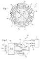
- FIG. 1 a rotary electric machine 1 whose stator 2 is configured according to the method according to the invention.
- This rotary electrical machine 1 is for example a synchronous or asynchronous machine and may have a nominal power of between 10W and 10 MW, in particular between 100W and 200kW.
- the machine 2 comprises a rotor 3 which is in the example considered at four poles.
- the rotor 3 may comprise permanent magnets.
- the stator 2 comprises a frame 5 on which coils 6 are arranged N j, N being greater than or equal to four. In the example considered, N is equal to six.
- the carcass 5 extends around an axis X called thereafter "stator axis".
- the stator 2 is supplied with current by a power supply device 7.
- the supply device 7 can be any electrical network.
- the supply device 7 delivers in the example in question to the stator 2 a three-phase current.
- the coils 6 j of the stator 2 are wound on a tooth but the invention also applies to a stator with distributed winding.
- the coils 6 j can be evenly distributed around the periphery of the axis X, that is to say that the angular distance ⁇ j j + 1 between the coils 6 j and 6 j + 1 is substantially constant on the periphery of the stator, the coils 6 j and 6 j + 1 designating two successive coils when moving around the axis X.
- the notation ⁇ will be adopted.
- the phase difference between the current i 1 and the currents i j vary in a strictly monotonic manner (modulo 2 ⁇ ) when the order j of the coils varies from 1 to 6. Coils diametrically opposed with respect to the axis X are traversed by currents in phase opposition in the example considered. Still in the example considered, the currents i 1 to i 6 have the same amplitude. These diametrically opposed coils are arranged in the example of the figure 1 facing poles of the rotor 3 of the same polarity.
- the rotating electrical machine 1 can be integrated into a subassembly 20 of an electric vehicle.
- This subset 20 comprises in the example of figures 2 and 3 a connector 21 configured to be connected to the power supply device 7, a converter 22 and a capacitor 23 connected in parallel across a not shown battery. If necessary, a DC / DC converter can be arranged between the converter 22 and the battery.
- the converter 22 comprises switches which may each comprise a power transistor at the terminals of which is mounted a diode in parallel.
- the switches are for example arranged in H-bridges.
- the converter comprises, for example, three bridges in H.
- Each H-bridge may then comprise two arms each having two Switches as described above and each terminal of a winding forming a phase of the stator can be connected between two switches of an arm of a bridge.
- the latter determines the shape of the currents i j according to a predetermined strategy.
- the converter 22 comprises H bridges, these can be ordered according to the teaching of the request WO 2010/057892 already mentioned.
- Subset 20 of figures 2 and 3 uses the stator windings 2 when charging the battery and the switches of the converter 22 but, in other examples, a specific charger could be provided.
- each coil 6 j is disposed on the carcass 5 of the stator.
- Each coil has an input power supply by the device 7 common to another coil.
- These two coils having a current common input form in the example considered the winding corresponding to an electrical phase of the stator 2.
- the winding of each phase of the stator is fed at its midpoint, that is to say that the two coils having a common current input have the same number of turns and that the currents i U , i V and i W respectively supplying the phases of the stator connected to the phases U, V and W of the supply device 7 are divided in two at their entry into the stator 2, a half i U1 , i V1 or i W1 of this current flowing in one coil while the other half i Ur , i Vr and i Wr flows in another coil.
- These coils having a current common current input will then be called “coil” and “complementary coil or dual” and these two coils form a couple "coil / coil dual".
- the terminals of the winding forming each phase of the stator can be respectively arranged between two switches of an arm of an H bridge while the midpoint of this winding is connected to the supply device 7
- the electrical diagram of the subassembly 20 of the electric vehicle is for example the same as that of FIG. WO 2010/057892 which is incorporated herein by reference.
- the coils of a couple can be traversed by currents of the same intensity but in opposition of phase.
- stator coils 2 can be connected to the supply device 7.
- the currents i U1 , i V1 and i W1 are out of phase with each other by 2 ⁇ / 3, just as the currents i Ur , i Vr and i Wr are out of phase with each other at the same angle value.
- the phase shift between the currents i U1 and i Ur , respectively between the currents i V1 and i Vr respectively between the currents i W1 and i Wr is equal to ⁇ .
- successive coils 6 j are obtained which are angularly offset by 2 ⁇ / 6 and such that the phase difference between the current flowing through the reference coil and the current flowing through each of the other coils and specific to it varies in a strictly monotonic manner and, in the example described regularly, when moving around the X axis.
- stator according to configuration "C” or “G” When the stator according to configuration "C” or “G” is associated with a rotor 3 of rotating electrical machine whose diametrically opposite poles are of the same polarity, the forces generated in the coils of a pair which are, according to these configurations, traversed by currents in phase opposition and which are diametrically opposite to the axis of the stator compensate, so that although the stator is electrically powered, the rotor does not rotate. It is thus possible to charge the battery using the components of the subassembly 20 without it being necessary to prevent the movements of the rotor.
- the matrix of inductances obtained using these equations can in particular have a good circularity which is conducive to the use of these mathematical transforms.
- the use of such mathematical tools can make it simpler to implement a command for charging the DC battery with the input of the inverter and the output of the motor. subset 20 three sinusoidal currents in phase with the voltages delivered by the power supply device 7 (this command is also called "operation in Power Factor Corrector").
- the stator according to the configuration "C” or “G” is associated with a rotor 3 of a rotating electrical machine whose diametrically opposite poles are of opposite polarity.
- the forces generated in the coils of a pair “coil / dual coil” which are, according to these configurations "C” or “G", traversed by currents in opposition of phase and which are diametrically opposed with respect to the axis of the stator, are added, so that the rotor 3 rotates.
- the invention is not limited to the examples which have just been described.
- the invention can for example be applied with a power supply device 7 comprising any number of phases and with a rotating electrical machine having any number of phases.
Landscapes
- Engineering & Computer Science (AREA)
- Power Engineering (AREA)
- Transportation (AREA)
- Mechanical Engineering (AREA)
- Windings For Motors And Generators (AREA)
- Control Of Eletrric Generators (AREA)
- Electric Propulsion And Braking For Vehicles (AREA)
- Charge And Discharge Circuits For Batteries Or The Like (AREA)
Abstract
Description
- La présente invention a pour objet un procédé de configuration d'un stator de machine électrique tournante, un procédé de charge d'une batterie d'un véhicule électrique comprenant une machine électrique tournante ayant un stator ainsi configuré et le système formé par un tel stator et le dispositif d'alimentation électrique auquel il est connecté.
- L'invention s'applique à tout type de machine électrique tournante, notamment mais non exclusivement aux machines synchrones ou asynchrones.
- Les machines électriques tournantes comprennent un stator ayant une carcasse sur laquelle sont bobinés des conducteurs électriques formant les bobines du stator. Ces machines électriques peuvent être utilisées pour la propulsion de véhicules hybrides ou électriques. De tels véhicules comportent alors une batterie servant à alimenter par l'intermédiaire d'un onduleur le moteur électrique pour faire tourner celui-ci.
- Lors de la charge de la batterie, celle-ci peut être connectée à un dispositif d'alimentation électrique, tel qu'un réseau de distribution d'énergie. Il est connu, par exemple de la demande
WO 2010/057892 , d'utiliser lors de la charge de la batterie du véhicule l'onduleur et les bobines du stator, de sorte que l'on conserve le même circuit électrique lorsque la batterie alimente le moteur et lorsque la batterie est en cours de recharge. - L'ordre selon lequel les bobines sont successivement disposées sur la carcasse d'un stator lorsque l'on se déplace autour de l'axe de ce stator peut ne pas respecter l'ordre temporel des courants parcourant chaque bobine. Cet ordre temporel des courants est donné par la valeur du déphasage entre le courant parcourant une bobine de référence, auquel on attribue arbitrairement une phase nulle, et le courant parcourant chacune des autres bobines du stator.
- Cet ordre temporel des courants sera par la suite appelé « ordre des courants ». A titre d'exemple, dans le cas de quatre courants régulièrement déphasés, les courants successifs sont ordonnés lorsqu'ils se succèdent sur le pourtour du stator selon l'ordre suivant :
- courant de phase nulle,
- courant déphasé par rapport au courant de phase nulle de 90°,
- courant déphasé par rapport au courant de phase nulle de 180° et,
- courant déphasé par rapport au courant de phase nulle de 270°.
- Or, la façon dont les bobines disposées sur la carcasse du stator sont connectées à un dispositif d'alimentation électrique influence le comportement de la machine électrique tournante, et notamment le contrôle de celle-ci.
- La demande
WO 97/02649 - Il existe un besoin pour configurer un stator de machine électrique tournante connecté à un dispositif d'alimentation électrique de manière à améliorer le fonctionnement de la machine, notamment pour rendre plus simple le contrôle des courants dans les bobines du stator de cette machine, ce qui peut s'avérer utile lorsque la machine électrique est alimentée par une batterie et que l'on souhaite recharger cette dernière.
- L'invention a pour but de répondre à ce besoin et elle y parvient, selon l'un de ses aspects, à l'aide d'un procédé de configuration d'un stator de machine électrique tournante, comprenant les étapes suivantes :
- disposer d'un stator ayant une carcasse sur laquelle des conducteurs électriques sont bobinés de manière à former N bobines, N étant supérieur ou égal à quatre et,
- connecter électriquement les bobines à un dispositif d'alimentation électrique de manière à ce que chaque bobine soit parcourue par un courant électrique propre délivré par le dispositif d'alimentation électrique,
- Avec un tel stator, l'ordre des bobines lorsque l'on se déplace autour de l'axe du stator est le même que l'ordre des courants propres à chaque bobine et parcourant ces dernières ou est l'ordre inverse de l'ordre des courants.
- Au sens de l'invention, un courant « propre à une bobine » est un courant ne circulant que dans la bobine en question et non dans les autres bobines du stator.
- Ce problème n'était pas perceptible dans le cas où l'on utilise une machine électrique tournante à trois bobines et alimentée en triphasé. En effet, dans ce cas, l'ordre des bobines autour de l'axe du stator correspond nécessairement à l'ordre des courants ou à l'ordre inverse des courants puisqu'à partir de la bobine de référence parcourue par un courant de phase nulle, on trouve successivement :
- soit la bobine ayant un courant en retard de 2Π/3 et la bobine dont le courant est en retard de 4Π/3, auquel cas l'ordre des bobines est le même que l'ordre des courants;
- soit la bobine ayant un courant en avance de 2Π/3 puis celle dont le courant est en avance de 4Π/3, auquel cas l'ordre des bobines est l'inverse de l'ordre des courants.
- Ainsi, l'invention permet que les bobines et les courants soient ordonnés lorsque l'on se déplace autour de l'axe du stator, dès lors que quatre bobines ou plus sont disposées sur la carcasse du stator.
- Le déphasage varie de façon strictement monotone, c'est-à-dire que déphasage entre le courant parcourant la bobine de référence et le courant parcourant une autre bobine et propre à cette dernière est strictement croissant ou décroissant lorsque l'on se déplace autour de l'axe du stator à partir de la bobine de référence. Par la suite, les valeurs d'angles électriques ou mécaniques doivent être comprises à 2Π près.
- Les bobines peuvent être réparties de façon uniforme autour de l'axe du stator et le déphasage peut croître ou décroître de façon régulière entre les bobines successives. « Bobines réparties de manière uniforme » signifie que la machine est régulièrement construite. Dans un tel cas, le décalage angulaire est sensiblement constant sur le pourtour du stator.
- Au sens de l'invention, le décalage angulaire entre deux bobines successives du stator peut être mesuré dans un plan perpendiculaire à l'axe du stator, entre les plans médians des bobines successives. Lorsque le stator est à bobinage sur dent, le décalage angulaire entre deux bobines successives peut être mesuré entre le plan médian de la dent autour de laquelle une bobine est bobinée et le plan médian de la dent autour de laquelle la bobine successive est bobinée.
- Deux bobines successives peuvent être décalées angulairement d'un angle mécanique sensiblement égal à 2.k.Π/N et lesdites deux bobines successives sont alimentées par des courants déphasés entre eux d'un angle électrique sensiblement égal à 2.k.Π/N. k est un entier relatif, étant par exemple égal à un.
- Une telle disposition angulaire des bobines et des courants les parcourant peut permettre de réaliser un contrôle efficace des performances de la machine.
- Les courants délivrés par le dispositif d'alimentation peuvent tous avoir la même amplitude.
- L'étape de bobinage peut avoir été effectuée préalablement à la mise en oeuvre du procédé ou faire partie du procédé.
- Le système d'alimentation électrique peut délivrer un courant polyphasé.
- La machine électrique tournante est par exemple une machine synchrone, notamment une machine synchrone à aimants permanents.
- Le stator peut être connecté au dispositif d'alimentation électrique, qui est par exemple un réseau électrique, sans l'intermédiaire d'un convertisseur de tension, notamment d'un redresseur. Le réseau électrique est par exemple d'un réseau industriel géré par un fournisseur d'énergie ou encore d'un réseau plus local, par exemple d'une éolienne ou d'un groupe électrogène.
- Selon un exemple de mise en oeuvre de l'invention, le système d'alimentation électrique délivre un courant triphasé et il est connecté aux bobines du stator de manière à ce que chaque bobine ait une entrée en courant depuis le dispositif d'alimentation commune avec une autre bobine, ladite autre bobine formant une bobine complémentaire de ladite bobine. Chaque bobine complémentaire d'une bobine sera par la suite également appelée « bobine duale » de ladite bobine. L'emploi d'une bobine duale peut permettre que les courants circulant dans un couple « bobine/ bobine duale » soient équilibrés et que l'onde de force magnétomotrice dans l'entrefer soit statique et ne crée pas de champ tournant, ce qui peut être utile dans des applications qui seront mentionnées ci-après.
- Le bobinage et la connexion peuvent être tels que ladite bobine et ladite bobine complémentaire sont diamétralement opposées par rapport à l'axe du stator et sont parcourues par des courants déphasés d'un angle électrique égal à Π. On peut ainsi obtenir pour chaque bobine un couple « bobine/ bobine complémentaire ou duale » où lesdites bobines du couple sont diamétralement opposées et parcourues par des courants en opposition de phase. Lorsqu'un tel stator est associé à un rotor dont les pôles diamétralement opposés ont la même polarité (étant par exemple deux pôles Nord ou deux pôles Sud), chaque bobine d'un couple « bobine/ bobine duale » donné voit strictement le même champ magnétique rotorique et produit alors un champ magnétique en opposition l'un par rapport à l'autre. Ainsi, l'effort produit par une bobine lorsqu'elle est plongée dans le champ magnétique rotorique et lorsqu'elle est parcourue par un courant délivré par le dispositif d'alimentation est compensé par l'effort produit par sa bobine duale plongée dans le même champ magnétique rotorique et parcourue par un courant en opposition de phase, de sorte que le rotor n'est que peu en mouvement, voire immobile.
- En variante, le stator peut être associé à un rotor dont les pôles diamétralement opposés ont des polarités opposées. Chaque bobine d'un couple voit alors un champ magnétique rotorique en opposition de phase, et ces bobines étant elles-mêmes parcourues par des courants en opposition de phase, elles vont générer des efforts s'additionnant et permettant la mise en rotation du rotor. Une bobine peut former une première partie de l'enroulement d'une phase du stator tandis que la bobine complémentaire ou duale de ladite bobine forme une deuxième partie distincte de la première de l'enroulement de ladite phase. L'enroulement de chaque phase du stator peut ainsi être composé par un couple « bobine/ bobine duale ».
- L'entrée en courant de l'enroulement d'une phase du stator, qui constitue l'entrée commune en courant d'un couple « bobine/ bobine duale » est par exemple disposée sensiblement au point milieu dudit enroulement, de sorte que le courant circulant dans une bobine ait sensiblement la même amplitude que le courant circulant dans la bobine complémentaire ou duale de ladite bobine.
- Le stator peut être à bobinage concentré ou réparti.
- Le rotor peut être à pôles lisses ou à pôles saillants.
- Le stator et le rotor peuvent comporter ou non le même nombre de pôles.
- Le dispositif d'alimentation électrique peut délivrer un courant alternatif. Ce courant peut avoir une fréquence de 50Hz ou 60Hz, par exemple.
- Le nombre de pôles du rotor est par exemple compris entre 2 et 20.
- L'invention a encore pour objet, selon un autre de ses aspects, un procédé de charge d'une batterie depuis un dispositif d'alimentation électrique en utilisant une machine électrique tournante, procédé dans lequel :
- on configure le stator de la machine électrique tournante en appliquant le procédé décrit ci-dessus et,
- on charge la batterie en utilisant les bobines du stator, les courants ayant circulé dans celles-ci étant redressés avant d'alimenter ensuite la batterie.
- Un tel procédé s'applique notamment dans le domaine des véhicules électriques, notamment des automobiles, dans lesquels la batterie peut alimenter le moteur via un onduleur lorsque celui-ci tourne et être rechargée lorsque le moteur est à l'arrêt. D'autres applications de ce procédé sont néanmoins possibles telles que pour la génération d'énergie éolienne ou hydraulique.
- Au sens de l'invention, «batterie » doit être compris comme englobant une ou plusieurs batteries qui soient aussi bien les batteries désignées de cette manière dans le commerce que les autres unités de stockage d'énergie, rechargeables ou non, telles que les super-condensateurs par exemple. Il peut s'agir d'une ou plusieurs batteries lithium-ion ou d'accumulateurs, par exemple au plomb ou de type Ni/Cd.
- Selon un tel procédé, par exemple décrit dans la demande
WO 2010/057893 , on peut charger la batterie du véhicule en utilisant les éléments du moteur et de l'onduleur tels que les bobines du stator du moteur et les commutateurs de l'onduleur. - La machine électrique tournante peut en particulier comporter un stator alimenté par un dispositif d'alimentation délivrant un courant triphasé, le dispositif d'alimentation étant relié aux bobines du stator de manière à ce que chaque bobine ait une entrée en courant depuis le dispositif d'alimentation commune avec une autre bobine de la carcasse, ladite autre bobine formant une bobine complémentaire de ladite bobine, ladite bobine et ladite bobine duale étant diamétralement opposées par rapport à l'axe du stator et parcourues par des courants déphasés d'un angle électrique égal à Π. Les bobines d'un couple « bobine/ bobine duale » peuvent composer l'enroulement d'une phase du stator et l'entrée en courant de cet enroulement peut être disposée sensiblement au point milieu dudit enroulement.
- Un onduleur comportant des commutateurs peut être disposé entre le stator et la batterie. Cet onduleur comporte par exemple des ponts en H et chaque bobine peut présenter une sortie connectée entre deux interrupteurs d'un bras d'un pont en H.
- La machine électrique tournante peut comporter un rotor configuré de manière à ce que le rotor soit immobile lorsque les bobines du stator sont alimentées en courant pour recharger la batterie. Cette immobilité peut être obtenue en choisissant un rotor à pôles diamétralement opposés de même polarité, de manière à ce que chaque couple « bobine/ bobine duale » voit un même champ magnétique rotorique et génère des efforts se compensant, étant donné qu'ils sont parcourus par des courants en opposition de phase. Avec une telle machine électrique, on peut utiliser les enroulements du stator lors de la charge de la batterie en réduisant autant que possible les mouvements du rotor, de manière à obtenir un chargeur statique.
- Cette application du procédé selon l'invention peut permettre d'éviter d'avoir à découpler le rotor de l'arbre de la machine lors de la charge et/ou d'avoir à appliquer des freins sur le moteur lors de la charge de la batterie.
- En variante, la machine électrique tournante peut comporter un rotor configuré de manière à ce que le rotor tourne lorsque les bobines du stator sont alimentées en courant lors de la charge.
- L'invention a encore pour objet, selon un autre de ses aspects, un système, comprenant :
- un stator de machine électrique tournante, comportant une carcasse et des conducteurs électriques bobinés sur la carcasse de manière à former N bobines, N étant supérieur ou égal à quatre, et
- un dispositif d'alimentation électrique délivrant à chaque bobine du stator un courant électrique propre,
- Lorsque l'on se déplace autour de l'axe du stator, deux bobines successives peuvent être décalées angulairement d'un angle mécanique sensiblement égal à 2.k.Π/N et lesdites bobines successives peuvent être connectées au réseau de manière à être respectivement alimentées par des courants déphasés entre eux d'un angle électrique sensiblement égal à 2.k.Π/N. k est un entier relatif, par exemple égal à un.
- Un tel système peut permettre d'obtenir les avantages mentionnés ci-dessus et peut être associé à tout ou partie des caractéristiques mentionnées ci-dessus en rapport avec les procédés décrits.
- L'invention pourra être mieux comprise à la lecture qui va suivre d'exemples non limitatifs de mise en oeuvre de celle-ci et à l'examen du dessin annexé sur lequel,
- la
figure 1 représente de façon schématique une machine électrique tournante ayant un stator configuré conformément au procédé selon l'invention, - les
figures 2 et3 représentent un sous-ensemble d'un véhicule électrique dans lequel un procédé de charge d'une batterie à l'aide d'un stator configuré selon l'invention peut être mis en oeuvre et, - la
figure 4 est un diagramme montrant les différentes possibilités de connecter les bobines du stator du moteur représenté auxfigures 2 et3 à un dispositif d'alimentation électrique. - On a représenté à la
figure 1 une machine électrique tournante 1 dont le stator 2 est configuré conformément au procédé selon l'invention. Cette machine électrique tournante 1 est par exemple une machine synchrone ou asynchrone et peut présenter une puissance nominale comprise entre 10W et 10 MW, notamment comprise entre 100W et 200kW. - La machine 2 comprend un rotor 3 qui est dans l'exemple considéré à quatre pôles. Dans le cas d'un rotor de machine synchrone, le rotor 3 peut comprendre des aimants permanents.
- Le stator 2 comporte une carcasse 5 sur laquelle sont disposées N bobines 6j, N étant supérieur ou égal à quatre. Dans l'exemple considéré, N est égal à six. La carcasse 5 s'étend autour d'un axe X appelé par la suite « axe du stator ». Dans l'exemple qui va être décrit, le stator 2 est alimenté en courant par un dispositif d'alimentation électrique 7. Le dispositif d'alimentation 7 peut être tout réseau électrique.
- Le dispositif d'alimentation 7 délivre dans l'exemple considéré au stator 2 un courant triphasé.
- Dans les exemples représentés, les bobines 6j du stator 2 sont bobinées sur dent mais l'invention s'applique également à un stator avec bobinage réparti.
- En outre, les exemples décrits concernent une machine à flux radial et à rotor interne mais l'invention peut également s'appliquer à une machine à flux axial et/ou à rotor externe.
- Comme on peut le voir sur la
figure 1 , les bobines 6j peuvent être réparties de façon uniforme sur le pourtour de l'axe X, c'est-à-dire que l'écart angulaire θj j+1 entre les bobines 6j et 6j+1 est sensiblement constant sur le pourtour du stator, les bobines 6j et 6j+1 désignant deux bobines successives lorsque l'on se déplace autour de l'axe X. On adoptera dans un tel cas de répartition uniforme des bobines 6j la notation θ. - Dans l'exemple de la
figure 1 , l'écart angulaire θ vaut 2Π/6. On considère comme bobine de référence la bobine 61. La phase du courant i1 parcourant cette dernière et propre à celle-ci est alors arbitrairement fixée comme nulle Le stator 2 de la machine électrique 1 est connecté au dispositif d'alimentation 7 de manière à ce qu'en se déplaçant à partir de la bobine 61 autour de l'axe X, on trouve successivement : - la bobine 62, qui est décalée par rapport à la bobine 61 de 2Π/6 est parcourue par un courant i2 de +2Π/6, respectivement de -2Π/6, par rapport au courant i1,
- la bobine 63, qui est décalée par rapport à la bobine 62 de 2Π/6 est parcourue par un courant i3 déphasé de +4Π/6, respectivement de -4Π/6, par rapport au courant i1,
- la bobine 64, qui est décalée par rapport à la bobine 63 de 2Π/6, c'est-à-dire de Π par rapport à la bobine 61, est parcourue par un courant i4 déphasé de Π par rapport au courant i1,
- la bobine 65, qui est décalée par rapport à la bobine 64 de 2Π/6 est parcourue par un courant i5 déphasé de +8Π/6, respectivement de -8Π/6, par rapport au courant i1, et
- la bobine 66, qui est décalée par rapport à la bobine 65 de 2Π/6 est parcourue par un courant i6 déphasé de +10Π/6, respectivement de -10Π/6, par rapport au courant i1.
- On constate ainsi que dans l'exemple de la
figure 1 , le déphasage entre le courant i1
et les courants ij varie de façon strictement monotone (modulo 2Π) lorsque l'ordre j des bobines varie de 1 à 6. Des bobines diamétralement opposées par rapport à l'axe X sont parcourues par des courants en opposition de phase dans l'exemple considéré. Toujours dans l'exemple considéré, les courants i1 à i6 ont la même amplitude. Ces bobines diamétralement opposées sont disposées dans l'exemple de lafigure 1 face à des pôles du rotor 3 de même polarité. - On va maintenant décrire, en référence aux figues 2 à 4, un exemple d'utilisation d'un stator configuré selon l'invention.
- La machine électrique tournante 1 peut être intégrée à un sous-ensemble 20 d'un véhicule électrique. Ce sous-ensemble 20 comprend dans l'exemple des
figures 2 et3 un connecteur 21 configuré pour être relié au dispositif d'alimentation électrique 7, un convertisseur 22 et un condensateur 23 monté en parallèle aux bornes d'une batterie non représentée. Le cas échéant, un convertisseur DC/DC peut être disposé entre le convertisseur 22 et la batterie. - Le convertisseur 22 comporte des commutateurs qui peuvent comprendre chacun un transistor de puissance aux bornes duquel est montée une diode en parallèle. Les commutateurs sont par exemple disposés selon des ponts en H. Dans le cas d'une alimentation en courant triphasé avec un stator 2 triphasé, le convertisseur comporte par exemple trois ponts en H. Chaque pont en H peut alors comporter deux bras ayant chacun deux interrupteurs tels que décrits ci-dessus et chaque borne d'un enroulement formant une phase du stator peut être connectée entre deux interrupteurs d'un bras d'un pont.
- Le convertisseur 22 est configuré de manière à ce que :
- lorsque la machine électrique tournante 1 entraîne le véhicule, le convertisseur joue le rôle d'onduleur pour alimenter la machine 1 depuis la batterie et
- lorsque l'on charge la batterie, par exemple depuis le dispositif d'alimentation électrique 7, le convertisseur 22 joue le rôle de redresseur pour charger la batterie en courant continu.
- Dans les deux modes de fonctionnement ci-dessus du convertisseur 22, ce dernier détermine la forme des courants ij selon une stratégie prédéterminée.
- Lorsque le convertisseur 22 comporte des ponts en H, ces derniers peuvent être commandés selon l'enseignement de la demande
WO 2010/057892 déjà citée. - Le sous-ensemble 20 des
figures 2 et3 utilise les enroulements du stator 2 lors de la charge de la batterie et les commutateurs du convertisseur 22 mais, dans d'autres exemples, un chargeur spécifique pourrait être prévu. - Comme on peut le voir sur les
figures 2 et3 , six bobines 6j sont disposées sur la carcasse 5 du stator. Chaque bobine possède une entrée en courant d'alimentation par le dispositif 7 commune à une autre bobine. Ces deux bobines ayant une entrée commune en courant forment dans l'exemple considéré l'enroulement correspondant à une phase électrique du stator 2. Dans l'exemple de lafigure 2 , l'enroulement de chaque phase du stator est alimenté en son point milieu, c'est-à-dire que les deux bobines ayant une entrée commune en courant ont le même nombre de spires et que les courants iU, iV et iW alimentant respectivement les phases du stator reliées aux phases U, V et W du dispositif d'alimentation 7 sont divisés en deux à leur entrée dans le stator 2, une moitié iU1, iV1 ou iW1 de ce courant circulant dans une bobine tandis que l'autre moitié iUr, iVr et iWr circule dans une autre bobine. Ces bobines ayant une entrée en courant commune en courant seront ensuite appelées « bobine » et « bobine complémentaire ou duale » et ces deux bobines forment un couple « bobine/ bobine duale ». - Dans l'exemple décrit, les bornes de l'enroulement formant chaque phase du stator peuvent être respectivement disposées entre deux commutateurs d'un bras d'un pont en H tandis que le point milieu de cet enroulement est connecté au dispositif d'alimentation 7. Le schéma électrique du sous-ensemble 20 du véhicule électrique est par exemple le même que celui de la Figure 5 de la demande
WO 2010/057892 qui est incorporé à la présente demande par référence. - Comme on peut le voir sur la
figure 3 , les bobines d'un couple peuvent être parcourues par des courants de même intensité mais en opposition de phase. - On va maintenant expliquer en référence à la
figure 4 de quelle façon les bobines du stator 2 peuvent être connectées au dispositif d'alimentation 7. - Comme on peut le voir sur cette
figure 4 , il existe huit façons de connecter les six bobines 6j disposées sur la carcasse du stator au dispositif 7 lorsque l'on cherche à ce que les bobines formant un couple « bobine/ bobine duale » qui sont parcourues par des courants en opposition de phase soient diamétralement opposées par rapport à l'axe X. - Sans cette dernière condition, dès lors que l'on a connecté une des bobines au dispositif d'alimentation 7, il existe 120 façons différentes de connecter les autres bobines 6j au dispositif d'alimentation 7 Selon l'invention, on cherche à ce que l'ordre des courants ij dans les bobines 6j varie de façon strictement monotone lorsque l'on se déplace autour de l'axe X du stator.
- Comme on peut le voir, les courants iU1, iV1 et iW1 sont déphasés entre eux de 2Π/3, tout comme sont déphasés entre eux de la même valeur d'angle les courants iUr, iVr et iWr. Par ailleurs, le déphasage entre les courants iU1 et iUr, respectivement entre les courants iV1 et iVr respectivement entre les courants iW1 et iWr, est égal à Π.
- Si l'on relie les bobines 6j du stator au dispositif d'alimentation 7 selon la configuration « C » de la
figure 4 , en considérant que la bobine 61, qui est reliée de manière à être alimentée par le courant iU1, est la bobine de référence pour le déphasage du courant, on trouve successivement les bobines et les courants suivants lorsque l'on se déplace autour de l'axe X à partir de la bobine de référence 61 : - la bobine 62 alimentée par le courant iVr déphasé de 2Π/6 par rapport à iU1,
- la bobine 63 alimentée par le courant iW1 déphasé de 4Π/6 par rapport à iU1,
- bobine 64 alimentée par le courant iUr déphasé de Π par rapport à iU1
- bobine 65 alimentée par le courant iV1 déphasé de 8Π/6 par rapport à iU1, et
- bobine 66 alimentée par le courant iWr déphasé de 10Π/6 par rapport à iU1.
- On obtient ainsi des bobines 6j successives angulairement décalées de 2Π/6 et telles que le déphasage entre le courant parcourant la bobine de référence et le courant parcourant chacune des autres bobines et propre à celle-ci varie de façon strictement monotone et, dans l'exemple décrit de façon régulière, lorsque l'on se déplace autour de l'axe X.
- On constate en observant la
figure 4 que la configuration « G » permet également d'obtenir la relation souhaitée entre disposition des bobines et variation du déphasage des courants les parcourant. - Lorsque le stator selon la configuration « C » ou « G » est associé à un rotor 3 de machine électrique tournante dont les pôles diamétralement opposés sont de même polarité, les efforts générés dans les bobines d'un couple qui sont, selon ces configurations, parcourues par des courants en opposition de phase et qui sont diamétralement opposées par rapport à l'axe du stator se compensent, de sorte que bien que le stator soit électriquement alimenté, le rotor ne tourne pas. On peut ainsi procéder à la charge de la batterie en utilisant les composants du sous-ensemble 20 sans qu'il soit nécessaire d'empêcher les mouvements du rotor.
- Le contrôle des courants circulant dans les enroulements du stator d'une telle machine peut être facilité. Avec un tel stator, on peut par exemple employer des outils mathématiques tels que les transformées de Park ou de Concordia ou la transformée de Park généralisée lorsque l'on travaille sur les équations matricielles reliant le courant parcourant chaque bobine et propre à celle-ci et la tension aux bornes de chaque bobine.
- La matrice des inductances obtenues à l'aide de ces équations peut notamment présenter une bonne circularité qui est propice à l'emploi de ces transformées mathématiques. Dans le cas d'une alimentation triphasée, l'emploi de tels outils mathématiques peut rendre plus simple la mise en oeuvre d'une commande assurant la charge de la batterie en courant continu avec en entrée de l'onduleur et en sortie du moteur du sous-ensemble 20 trois courants sinusoïdaux en phase avec les tensions délivrées par le dispositif d'alimentation électrique 7 (cette commande est encore appelée «fonctionnement en Power Factor Corrector »).
- En variante, le stator selon la configuration « C » ou « G » est associé à un rotor 3 de machine électrique tournante dont les pôles diamétralement opposés sont de polarité inverse. Dans ce cas, les efforts générés dans les bobines d'un couple « bobine/ bobine duale »qui sont, selon ces configurations « C » ou « G », parcourues par des courants en opposition de phase et qui sont diamétralement opposées par rapport à l'axe du stator, s'ajoutent, de sorte que le rotor 3 tourne.
- L'invention n'est pas limitée aux exemples qui viennent d'être décrits. L'invention peut par exemple s'appliquer avec un dispositif d'alimentation électrique 7 comportant un nombre quelconque de phases et avec une machine électrique tournante ayant un nombre quelconque de phases.
- L'expression « comportant un » doit être comprise comme signifiant « comportant au moins un », sauf lorsque le contraire est spécifié.
Claims (15)
- Procédé de configuration d'un stator (2) de machine électrique tournante (1), comprenant les étapes suivantes :- disposer d'un stator (2) ayant une carcasse (5) sur laquelle des conducteurs électriques sont bobinés de manière à former N bobines (6j), N étant supérieur ou égal à quatre et,- connecter électriquement les bobines (6j) à un dispositif d'alimentation électrique (7) de manière à ce que chaque bobine (6j) soit parcourue par un courant électrique propre (ij) délivré par le dispositif d'alimentation électrique (7),
la connexion du stator (2) au dispositif d'alimentation électrique (7) étant effectuée de telle sorte que lorsque l'on se déplace autour de l'axe (X) du stator (2) à partir d'une bobine de référence (61), le déphasage entre le courant (i1) parcourant ladite bobine de référence et le courant (ij) propre à chacune des autres bobines (6j) varie de façon strictement monotone au fur et à mesure du déplacement à partir de ladite bobine de référence (61). - Procédé selon la revendication 1, dans lequel les bobines (6j) sont réparties de façon uniforme autour de l'axe (X) du stator et dans lequel le déphasage des courants (ij) varie de façon régulière entre les bobines successives(6j).
- Procédé selon la revendication 2, dans lequel deux bobines successives (6j) sont décalées angulairement d'un angle mécanique (θ) sensiblement égal à 2.k.Π/N et lesdites deux bobines successives (6j) sont alimentées par des courants (ij) déphasés entre eux d'un angle électrique sensiblement égal à 2.k.Π/N, k étant un entier relatif.
- Procédé selon l'une quelconque des revendications 1 à 3, dans lequel les courants (ij) délivrés par le dispositif d'alimentation (7) ont tous la même amplitude.
- Procédé selon l'une des revendications précédentes, dans lequel le dispositif d'alimentation électrique délivre un courant triphasé et est connecté aux bobines (6j) du stator (2) de manière à ce que chaque bobine (6j) ait une entrée en courant depuis le dispositif d'alimentation (7) commune avec une autre bobine (6j) du stator (2), ladite autre bobine formant une bobine complémentaire de ladite bobine.
- Procédé selon la revendication 5, dans lequel le bobinage et la connexion des bobines (6j) sont tels que ladite bobine et ladite bobine complémentaire sont diamétralement opposées par rapport à l'axe (X) du stator et sont parcourues par des courants (ij) déphasés d'un angle électrique égal à Π.
- Procédé selon la revendication précédente, dans lequel une bobine (6j) forme une première partie de l'enroulement d'une phase du stator tandis que la bobine complémentaire (6j) de ladite bobine forme une deuxième partie distincte de la première partie de l'enroulement de ladite phase.
- Procédé selon la revendication 7, dans lequel l'entrée en courant de l'enroulement d'une phase du stator est disposée sensiblement au point milieu dudit enroulement.
- Procédé selon l'une quelconque des revendications précédentes, dans lequel la machine électrique tournante est une machine synchrone.
- Procédé selon l'une quelconque des revendications précédentes, dans lequel le dispositif d'alimentation électrique est un réseau électrique que l'on connecte aux bobines (6j) du stator sans convertisseur de tension.
- Procédé de charge d'une batterie depuis un dispositif d'alimentation électrique (7) à l'aide d'une machine électrique tournante (1), dans lequel :- on configure le stator (2) de la machine électrique tournante en appliquant le procédé selon l'une quelconque des revendications 1 à 10 et,- on charge la batterie en utilisant les bobines (6j) du stator, les courants (ij) ayant circulé dans celles-ci étant redressés avant d'alimenter ensuite la batterie.
- Procédé selon la revendication 11, la machine électrique tournante (1) ayant un stator (2) configuré selon la revendication 8.
- Procédé de charge selon la revendication 11 ou 12, dans lequel la machine électrique tournante (1) comporte un rotor (3) configuré de manière à ce que le rotor (3) soit immobile ou tourne lorsque les bobines (6j) du stator (2) sont alimentées en courant pour recharger la batterie.
- Système, comprenant :- un stator (2) de machine électrique tournante (1), comportant une carcasse (5) et des conducteurs électriques bobinés sur la carcasse de manière à former N bobines (6j), N étant supérieur ou égal à quatre, et- un dispositif d'alimentation électrique (7) délivrant à chaque bobine (6j) un courant électrique propre (ij),
la connexion du stator (2) au dispositif d'alimentation électrique (7) étant effectuée de telle sorte que lorsque l'on se déplace autour de l'axe (X) du stator (2) à partir d'une bobine de référence (61), le déphasage entre le courant (i1) parcourant ladite bobine de référence (61) et le courant (ij) propre à chacune des autres bobines (6j) varie de façon strictement monotone au fur et à mesure du déplacement à partie de ladite bobine de référence (61). - Système selon la revendication 14, deux bobines successives (6j) lorsque l'on se déplace autour de l'axe (X) du stator (2) étant décalées angulairement d'un angle mécanique (θ) sensiblement égal à 2.k.Π/N et lesdites bobines successives (6j) étant connectées au dispositif d'alimentation électrique (7) de manière à être respectivement alimentées par des courants (ij) déphasés entre eux d'un angle électrique sensiblement égal à 2.k.Π/N, k étant un entier relatif.
Applications Claiming Priority (1)
| Application Number | Priority Date | Filing Date | Title |
|---|---|---|---|
| FR1155602A FR2977091B1 (fr) | 2011-06-24 | 2011-06-24 | Configuration d'un stator d'une machine electrique tournante |
Publications (2)
| Publication Number | Publication Date |
|---|---|
| EP2537702A1 true EP2537702A1 (fr) | 2012-12-26 |
| EP2537702B1 EP2537702B1 (fr) | 2019-11-27 |
Family
ID=46207941
Family Applications (1)
| Application Number | Title | Priority Date | Filing Date |
|---|---|---|---|
| EP12305641.8A Active EP2537702B1 (fr) | 2011-06-24 | 2012-06-06 | Procédé de configuration d'un stator de machine électrique tournante |
Country Status (7)
| Country | Link |
|---|---|
| US (1) | US9124202B2 (fr) |
| EP (1) | EP2537702B1 (fr) |
| JP (2) | JP6286115B2 (fr) |
| KR (1) | KR101927534B1 (fr) |
| CN (1) | CN102842997B (fr) |
| FR (1) | FR2977091B1 (fr) |
| HU (1) | HUE048297T2 (fr) |
Cited By (3)
| Publication number | Priority date | Publication date | Assignee | Title |
|---|---|---|---|---|
| EP3118976A1 (fr) * | 2015-07-17 | 2017-01-18 | Universite Catholique De Louvain | Machine électrique comportant un palier électrodynamique radial |
| US12095320B2 (en) | 2022-06-27 | 2024-09-17 | Anthropocene Institute LLC | Axial flux switched reluctance and inductance state machine systems, devices, and methods |
| US12149134B2 (en) | 2022-06-27 | 2024-11-19 | Anthropocene Institute LLC | Axial flux switched reluctance motor and generator, and related systems and methods |
Families Citing this family (2)
| Publication number | Priority date | Publication date | Assignee | Title |
|---|---|---|---|---|
| DE102013102900A1 (de) * | 2013-03-21 | 2014-09-25 | Feaam Gmbh | Synchronmaschine |
| CN109716625B (zh) * | 2016-06-23 | 2021-03-02 | 萨卢奇控股有限公司 | 一种包括转子、定子和电力电子装置的无刷式电机系统 |
Citations (3)
| Publication number | Priority date | Publication date | Assignee | Title |
|---|---|---|---|---|
| WO1997002649A1 (fr) | 1995-07-05 | 1997-01-23 | The University Of Warwick | Systeme a machine electrique a reluctance commutee |
| WO2010057892A1 (fr) | 2008-11-18 | 2010-05-27 | Valeo Systemes De Controle Moteur | Dispositif electrique combine d'alimentation et de charge |
| WO2010057893A1 (fr) | 2008-11-18 | 2010-05-27 | Valeo Systemes De Controle Moteur | Procede et dispositif electrique combine d'alimentation et de charge a moyens de compensation |
Family Cites Families (6)
| Publication number | Priority date | Publication date | Assignee | Title |
|---|---|---|---|---|
| US6064122A (en) * | 1998-11-05 | 2000-05-16 | Alliedsignal Power Systems Inc. | Microturbine power of generating system including a battery source for supplying startup power |
| JP2000316297A (ja) * | 1999-04-27 | 2000-11-14 | Mitsuba Corp | 始動発電機 |
| EP1256164A2 (fr) * | 2000-02-09 | 2002-11-13 | Dana Corporation | Procede d'exploitation d'un generateur electrique commute a reaction |
| US6333622B1 (en) * | 2000-05-16 | 2001-12-25 | General Electric Company | Synchronous generator having auxiliary power windings and variable frequency power source |
| JP4447001B2 (ja) * | 2006-12-19 | 2010-04-07 | トヨタ自動車株式会社 | 電力制御装置およびそれを備えた車両 |
| JP4727636B2 (ja) * | 2007-09-13 | 2011-07-20 | トヨタ自動車株式会社 | 車両の充電制御装置および車両 |
-
2011
- 2011-06-24 FR FR1155602A patent/FR2977091B1/fr active Active
-
2012
- 2012-06-06 EP EP12305641.8A patent/EP2537702B1/fr active Active
- 2012-06-06 HU HUE12305641A patent/HUE048297T2/hu unknown
- 2012-06-21 KR KR1020120066819A patent/KR101927534B1/ko active Active
- 2012-06-22 JP JP2012140431A patent/JP6286115B2/ja active Active
- 2012-06-25 US US13/531,931 patent/US9124202B2/en active Active
- 2012-06-25 CN CN201210214000.2A patent/CN102842997B/zh active Active
-
2016
- 2016-08-05 JP JP2016155110A patent/JP2016208838A/ja active Pending
Patent Citations (3)
| Publication number | Priority date | Publication date | Assignee | Title |
|---|---|---|---|---|
| WO1997002649A1 (fr) | 1995-07-05 | 1997-01-23 | The University Of Warwick | Systeme a machine electrique a reluctance commutee |
| WO2010057892A1 (fr) | 2008-11-18 | 2010-05-27 | Valeo Systemes De Controle Moteur | Dispositif electrique combine d'alimentation et de charge |
| WO2010057893A1 (fr) | 2008-11-18 | 2010-05-27 | Valeo Systemes De Controle Moteur | Procede et dispositif electrique combine d'alimentation et de charge a moyens de compensation |
Cited By (4)
| Publication number | Priority date | Publication date | Assignee | Title |
|---|---|---|---|---|
| EP3118976A1 (fr) * | 2015-07-17 | 2017-01-18 | Universite Catholique De Louvain | Machine électrique comportant un palier électrodynamique radial |
| US12095320B2 (en) | 2022-06-27 | 2024-09-17 | Anthropocene Institute LLC | Axial flux switched reluctance and inductance state machine systems, devices, and methods |
| US12149134B2 (en) | 2022-06-27 | 2024-11-19 | Anthropocene Institute LLC | Axial flux switched reluctance motor and generator, and related systems and methods |
| US12580465B2 (en) | 2022-06-27 | 2026-03-17 | Anthropocene Institute LLC | Axial flux switched reluctance and inductance state machine systems, devices, and methods |
Also Published As
| Publication number | Publication date |
|---|---|
| HUE048297T2 (hu) | 2020-07-28 |
| CN102842997A (zh) | 2012-12-26 |
| JP2013009586A (ja) | 2013-01-10 |
| FR2977091A1 (fr) | 2012-12-28 |
| EP2537702B1 (fr) | 2019-11-27 |
| KR20130001149A (ko) | 2013-01-03 |
| CN102842997B (zh) | 2017-04-12 |
| US9124202B2 (en) | 2015-09-01 |
| US20120326666A1 (en) | 2012-12-27 |
| KR101927534B1 (ko) | 2018-12-10 |
| JP2016208838A (ja) | 2016-12-08 |
| FR2977091B1 (fr) | 2013-06-21 |
| JP6286115B2 (ja) | 2018-02-28 |
Similar Documents
| Publication | Publication Date | Title |
|---|---|---|
| WO2012110979A1 (fr) | Ensemble fonctionnant a regime variable | |
| EP1609226B1 (fr) | Machine electrique synchrone comportant un stator et au moins un retor et dispositif de commande associe | |
| EP2537702B1 (fr) | Procédé de configuration d'un stator de machine électrique tournante | |
| FR2947115A1 (fr) | Machine dynamoelectrique | |
| FR2947970A1 (fr) | Convertisseur de puissance pour une machine électrique rotative | |
| EP4320720A1 (fr) | Dispositif de création d'un bus de tension continue pour un système électrique polyphase, véhicule automobile et générateur à énergie renouvelable comprenant un tel dispositif | |
| FR2808933A1 (fr) | Generatrice de courant alternatif utilisable dans un vehicule | |
| FR3038796A1 (fr) | Systeme de generation d'energie a traitement ameliore des impacts a charge, des delestages et des harmoniques | |
| WO2014023888A2 (fr) | Systeme de commande du couple electromagnetique d'une machine electrique notamment pour vehicule automobile | |
| Ziane et al. | Fixed-switching-frequency DTC control for PM synchronous machine with minimum torque ripples | |
| EP2638620A2 (fr) | Machine electrique a bobinage dentaire a phases regroupees | |
| EP3053262A2 (fr) | Machine electrique tournante polyphasee a au moins cinq phases | |
| EP2078332A1 (fr) | Rotor a griffes muni d'elements ferromagnetiques interpolaires de largeur optimisee et machine tournante equipee d'un tel rotor | |
| FR3049408A1 (fr) | Procede et systeme de conversion electrique continu-continu entre reseaux d'alimentation electrique relies a une machine electrique tournante de vehicule automobile | |
| EP2302768B1 (fr) | Dispositif d'alimentation en courant continu d'un bobinage de rotor d'une machine tournante électrique synchrone, et système d'entraînement comportant un tel dispositif d'alimentation | |
| FR3011405A1 (fr) | Machine electrique tournante polyphasee a au moins cinq phases a commande optimisee | |
| WO2015001279A2 (fr) | Procédé de commande d'un convertisseur de tension continu/alternatif | |
| FR3157027A1 (fr) | Rotor bobiné à pôles magnétiques reconfigurables et système d’excitation associé | |
| FR3098043A1 (fr) | Machine électrique synchrone polyphasée à commutateur mécanique | |
| EP4128521A2 (fr) | Procédé de commande d'un redresseur connecté à une génératrice électrique synchrone à aimants permanents pour fournir une tension continue, programme d'ordinateur et dispositif correspondant | |
| FR3098044A1 (fr) | Machine électrique synchrone polyphasée à commutateur mécanique | |
| EP3499692A1 (fr) | Moteur electrique a courant continu sans balai et vehicule associe | |
| FR2988927A1 (fr) | Procede de decharge d'au moins une unite de stockage d'energie electrique, notamment un condensateur, d'un circuit electrique | |
| FR3005811A1 (fr) | Procede de fabrication d'une machine electrique tournante synchrone polyphasee, et machine correspondante |
Legal Events
| Date | Code | Title | Description |
|---|---|---|---|
| PUAI | Public reference made under article 153(3) epc to a published international application that has entered the european phase |
Free format text: ORIGINAL CODE: 0009012 |
|
| AK | Designated contracting states |
Kind code of ref document: A1 Designated state(s): AL AT BE BG CH CY CZ DE DK EE ES FI FR GB GR HR HU IE IS IT LI LT LU LV MC MK MT NL NO PL PT RO RS SE SI SK SM TR |
|
| AX | Request for extension of the european patent |
Extension state: BA ME |
|
| 17P | Request for examination filed |
Effective date: 20130613 |
|
| RBV | Designated contracting states (corrected) |
Designated state(s): AL AT BE BG CH CY CZ DE DK EE ES FI FR GB GR HR HU IE IS IT LI LT LU LV MC MK MT NL NO PL PT RO RS SE SI SK SM TR |
|
| STAA | Information on the status of an ep patent application or granted ep patent |
Free format text: STATUS: EXAMINATION IS IN PROGRESS |
|
| 17Q | First examination report despatched |
Effective date: 20170726 |
|
| REG | Reference to a national code |
Ref country code: DE Ref legal event code: R079 Ref document number: 602012065992 Country of ref document: DE Free format text: PREVIOUS MAIN CLASS: B60L0011180000 Ipc: H02J0007020000 |
|
| GRAP | Despatch of communication of intention to grant a patent |
Free format text: ORIGINAL CODE: EPIDOSNIGR1 |
|
| STAA | Information on the status of an ep patent application or granted ep patent |
Free format text: STATUS: GRANT OF PATENT IS INTENDED |
|
| RIC1 | Information provided on ipc code assigned before grant |
Ipc: H02P 6/08 20160101ALI20190604BHEP Ipc: H02P 3/02 20060101ALI20190604BHEP Ipc: H02J 7/02 20160101AFI20190604BHEP |
|
| INTG | Intention to grant announced |
Effective date: 20190628 |
|
| RAP1 | Party data changed (applicant data changed or rights of an application transferred) |
Owner name: VALEO SIEMENS EAUTOMOTIVE FRANCE SAS |
|
| GRAS | Grant fee paid |
Free format text: ORIGINAL CODE: EPIDOSNIGR3 |
|
| GRAA | (expected) grant |
Free format text: ORIGINAL CODE: 0009210 |
|
| STAA | Information on the status of an ep patent application or granted ep patent |
Free format text: STATUS: THE PATENT HAS BEEN GRANTED |
|
| AK | Designated contracting states |
Kind code of ref document: B1 Designated state(s): AL AT BE BG CH CY CZ DE DK EE ES FI FR GB GR HR HU IE IS IT LI LT LU LV MC MK MT NL NO PL PT RO RS SE SI SK SM TR |
|
| REG | Reference to a national code |
Ref country code: GB Ref legal event code: FG4D Free format text: NOT ENGLISH |
|
| REG | Reference to a national code |
Ref country code: CH Ref legal event code: EP |
|
| REG | Reference to a national code |
Ref country code: AT Ref legal event code: REF Ref document number: 1207819 Country of ref document: AT Kind code of ref document: T Effective date: 20191215 |
|
| REG | Reference to a national code |
Ref country code: DE Ref legal event code: R096 Ref document number: 602012065992 Country of ref document: DE |
|
| REG | Reference to a national code |
Ref country code: IE Ref legal event code: FG4D Free format text: LANGUAGE OF EP DOCUMENT: FRENCH |
|
| REG | Reference to a national code |
Ref country code: NL Ref legal event code: MP Effective date: 20191127 |
|
| REG | Reference to a national code |
Ref country code: LT Ref legal event code: MG4D |
|
| PG25 | Lapsed in a contracting state [announced via postgrant information from national office to epo] |
Ref country code: LT Free format text: LAPSE BECAUSE OF FAILURE TO SUBMIT A TRANSLATION OF THE DESCRIPTION OR TO PAY THE FEE WITHIN THE PRESCRIBED TIME-LIMIT Effective date: 20191127 Ref country code: NL Free format text: LAPSE BECAUSE OF FAILURE TO SUBMIT A TRANSLATION OF THE DESCRIPTION OR TO PAY THE FEE WITHIN THE PRESCRIBED TIME-LIMIT Effective date: 20191127 Ref country code: BG Free format text: LAPSE BECAUSE OF FAILURE TO SUBMIT A TRANSLATION OF THE DESCRIPTION OR TO PAY THE FEE WITHIN THE PRESCRIBED TIME-LIMIT Effective date: 20200227 Ref country code: LV Free format text: LAPSE BECAUSE OF FAILURE TO SUBMIT A TRANSLATION OF THE DESCRIPTION OR TO PAY THE FEE WITHIN THE PRESCRIBED TIME-LIMIT Effective date: 20191127 Ref country code: SE Free format text: LAPSE BECAUSE OF FAILURE TO SUBMIT A TRANSLATION OF THE DESCRIPTION OR TO PAY THE FEE WITHIN THE PRESCRIBED TIME-LIMIT Effective date: 20191127 Ref country code: FI Free format text: LAPSE BECAUSE OF FAILURE TO SUBMIT A TRANSLATION OF THE DESCRIPTION OR TO PAY THE FEE WITHIN THE PRESCRIBED TIME-LIMIT Effective date: 20191127 Ref country code: ES Free format text: LAPSE BECAUSE OF FAILURE TO SUBMIT A TRANSLATION OF THE DESCRIPTION OR TO PAY THE FEE WITHIN THE PRESCRIBED TIME-LIMIT Effective date: 20191127 Ref country code: NO Free format text: LAPSE BECAUSE OF FAILURE TO SUBMIT A TRANSLATION OF THE DESCRIPTION OR TO PAY THE FEE WITHIN THE PRESCRIBED TIME-LIMIT Effective date: 20200227 Ref country code: GR Free format text: LAPSE BECAUSE OF FAILURE TO SUBMIT A TRANSLATION OF THE DESCRIPTION OR TO PAY THE FEE WITHIN THE PRESCRIBED TIME-LIMIT Effective date: 20200228 |
|
| PG25 | Lapsed in a contracting state [announced via postgrant information from national office to epo] |
Ref country code: RS Free format text: LAPSE BECAUSE OF FAILURE TO SUBMIT A TRANSLATION OF THE DESCRIPTION OR TO PAY THE FEE WITHIN THE PRESCRIBED TIME-LIMIT Effective date: 20191127 Ref country code: HR Free format text: LAPSE BECAUSE OF FAILURE TO SUBMIT A TRANSLATION OF THE DESCRIPTION OR TO PAY THE FEE WITHIN THE PRESCRIBED TIME-LIMIT Effective date: 20191127 Ref country code: IS Free format text: LAPSE BECAUSE OF FAILURE TO SUBMIT A TRANSLATION OF THE DESCRIPTION OR TO PAY THE FEE WITHIN THE PRESCRIBED TIME-LIMIT Effective date: 20200327 |
|
| PG25 | Lapsed in a contracting state [announced via postgrant information from national office to epo] |
Ref country code: AL Free format text: LAPSE BECAUSE OF FAILURE TO SUBMIT A TRANSLATION OF THE DESCRIPTION OR TO PAY THE FEE WITHIN THE PRESCRIBED TIME-LIMIT Effective date: 20191127 |
|
| REG | Reference to a national code |
Ref country code: HU Ref legal event code: AG4A Ref document number: E048297 Country of ref document: HU |
|
| PG25 | Lapsed in a contracting state [announced via postgrant information from national office to epo] |
Ref country code: RO Free format text: LAPSE BECAUSE OF FAILURE TO SUBMIT A TRANSLATION OF THE DESCRIPTION OR TO PAY THE FEE WITHIN THE PRESCRIBED TIME-LIMIT Effective date: 20191127 Ref country code: CZ Free format text: LAPSE BECAUSE OF FAILURE TO SUBMIT A TRANSLATION OF THE DESCRIPTION OR TO PAY THE FEE WITHIN THE PRESCRIBED TIME-LIMIT Effective date: 20191127 Ref country code: PT Free format text: LAPSE BECAUSE OF FAILURE TO SUBMIT A TRANSLATION OF THE DESCRIPTION OR TO PAY THE FEE WITHIN THE PRESCRIBED TIME-LIMIT Effective date: 20200419 Ref country code: EE Free format text: LAPSE BECAUSE OF FAILURE TO SUBMIT A TRANSLATION OF THE DESCRIPTION OR TO PAY THE FEE WITHIN THE PRESCRIBED TIME-LIMIT Effective date: 20191127 Ref country code: DK Free format text: LAPSE BECAUSE OF FAILURE TO SUBMIT A TRANSLATION OF THE DESCRIPTION OR TO PAY THE FEE WITHIN THE PRESCRIBED TIME-LIMIT Effective date: 20191127 |
|
| REG | Reference to a national code |
Ref country code: DE Ref legal event code: R097 Ref document number: 602012065992 Country of ref document: DE |
|
| PG25 | Lapsed in a contracting state [announced via postgrant information from national office to epo] |
Ref country code: SM Free format text: LAPSE BECAUSE OF FAILURE TO SUBMIT A TRANSLATION OF THE DESCRIPTION OR TO PAY THE FEE WITHIN THE PRESCRIBED TIME-LIMIT Effective date: 20191127 Ref country code: SK Free format text: LAPSE BECAUSE OF FAILURE TO SUBMIT A TRANSLATION OF THE DESCRIPTION OR TO PAY THE FEE WITHIN THE PRESCRIBED TIME-LIMIT Effective date: 20191127 |
|
| REG | Reference to a national code |
Ref country code: AT Ref legal event code: MK05 Ref document number: 1207819 Country of ref document: AT Kind code of ref document: T Effective date: 20191127 |
|
| PLBE | No opposition filed within time limit |
Free format text: ORIGINAL CODE: 0009261 |
|
| STAA | Information on the status of an ep patent application or granted ep patent |
Free format text: STATUS: NO OPPOSITION FILED WITHIN TIME LIMIT |
|
| 26N | No opposition filed |
Effective date: 20200828 |
|
| PG25 | Lapsed in a contracting state [announced via postgrant information from national office to epo] |
Ref country code: AT Free format text: LAPSE BECAUSE OF FAILURE TO SUBMIT A TRANSLATION OF THE DESCRIPTION OR TO PAY THE FEE WITHIN THE PRESCRIBED TIME-LIMIT Effective date: 20191127 Ref country code: PL Free format text: LAPSE BECAUSE OF FAILURE TO SUBMIT A TRANSLATION OF THE DESCRIPTION OR TO PAY THE FEE WITHIN THE PRESCRIBED TIME-LIMIT Effective date: 20191127 Ref country code: SI Free format text: LAPSE BECAUSE OF FAILURE TO SUBMIT A TRANSLATION OF THE DESCRIPTION OR TO PAY THE FEE WITHIN THE PRESCRIBED TIME-LIMIT Effective date: 20191127 |
|
| PG25 | Lapsed in a contracting state [announced via postgrant information from national office to epo] |
Ref country code: IT Free format text: LAPSE BECAUSE OF FAILURE TO SUBMIT A TRANSLATION OF THE DESCRIPTION OR TO PAY THE FEE WITHIN THE PRESCRIBED TIME-LIMIT Effective date: 20191127 Ref country code: MC Free format text: LAPSE BECAUSE OF FAILURE TO SUBMIT A TRANSLATION OF THE DESCRIPTION OR TO PAY THE FEE WITHIN THE PRESCRIBED TIME-LIMIT Effective date: 20191127 |
|
| REG | Reference to a national code |
Ref country code: CH Ref legal event code: PL |
|
| PG25 | Lapsed in a contracting state [announced via postgrant information from national office to epo] |
Ref country code: LU Free format text: LAPSE BECAUSE OF NON-PAYMENT OF DUE FEES Effective date: 20200606 |
|
| REG | Reference to a national code |
Ref country code: BE Ref legal event code: MM Effective date: 20200630 |
|
| PG25 | Lapsed in a contracting state [announced via postgrant information from national office to epo] |
Ref country code: CH Free format text: LAPSE BECAUSE OF NON-PAYMENT OF DUE FEES Effective date: 20200630 Ref country code: IE Free format text: LAPSE BECAUSE OF NON-PAYMENT OF DUE FEES Effective date: 20200606 Ref country code: LI Free format text: LAPSE BECAUSE OF NON-PAYMENT OF DUE FEES Effective date: 20200630 |
|
| PG25 | Lapsed in a contracting state [announced via postgrant information from national office to epo] |
Ref country code: BE Free format text: LAPSE BECAUSE OF NON-PAYMENT OF DUE FEES Effective date: 20200630 |
|
| PG25 | Lapsed in a contracting state [announced via postgrant information from national office to epo] |
Ref country code: TR Free format text: LAPSE BECAUSE OF FAILURE TO SUBMIT A TRANSLATION OF THE DESCRIPTION OR TO PAY THE FEE WITHIN THE PRESCRIBED TIME-LIMIT Effective date: 20191127 Ref country code: MT Free format text: LAPSE BECAUSE OF FAILURE TO SUBMIT A TRANSLATION OF THE DESCRIPTION OR TO PAY THE FEE WITHIN THE PRESCRIBED TIME-LIMIT Effective date: 20191127 Ref country code: CY Free format text: LAPSE BECAUSE OF FAILURE TO SUBMIT A TRANSLATION OF THE DESCRIPTION OR TO PAY THE FEE WITHIN THE PRESCRIBED TIME-LIMIT Effective date: 20191127 |
|
| PG25 | Lapsed in a contracting state [announced via postgrant information from national office to epo] |
Ref country code: MK Free format text: LAPSE BECAUSE OF FAILURE TO SUBMIT A TRANSLATION OF THE DESCRIPTION OR TO PAY THE FEE WITHIN THE PRESCRIBED TIME-LIMIT Effective date: 20191127 |
|
| P01 | Opt-out of the competence of the unified patent court (upc) registered |
Effective date: 20230629 |
|
| PGFP | Annual fee paid to national office [announced via postgrant information from national office to epo] |
Ref country code: DE Payment date: 20250617 Year of fee payment: 14 |
|
| PGFP | Annual fee paid to national office [announced via postgrant information from national office to epo] |
Ref country code: GB Payment date: 20250625 Year of fee payment: 14 |
|
| PGFP | Annual fee paid to national office [announced via postgrant information from national office to epo] |
Ref country code: HU Payment date: 20250530 Year of fee payment: 14 Ref country code: FR Payment date: 20250630 Year of fee payment: 14 |