EP2537619A1 - Build-up welding method of fabricating a component and a manufactured component - Google Patents
Build-up welding method of fabricating a component and a manufactured component Download PDFInfo
- Publication number
- EP2537619A1 EP2537619A1 EP12172275A EP12172275A EP2537619A1 EP 2537619 A1 EP2537619 A1 EP 2537619A1 EP 12172275 A EP12172275 A EP 12172275A EP 12172275 A EP12172275 A EP 12172275A EP 2537619 A1 EP2537619 A1 EP 2537619A1
- Authority
- EP
- European Patent Office
- Prior art keywords
- molten material
- boundary
- nickel
- composition
- tungsten
- Prior art date
- Legal status (The legal status is an assumption and is not a legal conclusion. Google has not performed a legal analysis and makes no representation as to the accuracy of the status listed.)
- Granted
Links
Images


Classifications
-
- B—PERFORMING OPERATIONS; TRANSPORTING
- B23—MACHINE TOOLS; METAL-WORKING NOT OTHERWISE PROVIDED FOR
- B23K—SOLDERING OR UNSOLDERING; WELDING; CLADDING OR PLATING BY SOLDERING OR WELDING; CUTTING BY APPLYING HEAT LOCALLY, e.g. FLAME CUTTING; WORKING BY LASER BEAM
- B23K35/00—Rods, electrodes, materials, or media, for use in soldering, welding, or cutting
- B23K35/22—Rods, electrodes, materials, or media, for use in soldering, welding, or cutting characterised by the composition or nature of the material
- B23K35/24—Selection of soldering or welding materials proper
- B23K35/30—Selection of soldering or welding materials proper with the principal constituent melting at less than 1550°C
- B23K35/3033—Ni as the principal constituent
- B23K35/304—Ni as the principal constituent with Cr as the next major constituent
-
- B—PERFORMING OPERATIONS; TRANSPORTING
- B23—MACHINE TOOLS; METAL-WORKING NOT OTHERWISE PROVIDED FOR
- B23K—SOLDERING OR UNSOLDERING; WELDING; CLADDING OR PLATING BY SOLDERING OR WELDING; CUTTING BY APPLYING HEAT LOCALLY, e.g. FLAME CUTTING; WORKING BY LASER BEAM
- B23K10/00—Welding or cutting by means of a plasma
- B23K10/02—Plasma welding
- B23K10/027—Welding for purposes other than joining, e.g. build-up welding
-
- B—PERFORMING OPERATIONS; TRANSPORTING
- B23—MACHINE TOOLS; METAL-WORKING NOT OTHERWISE PROVIDED FOR
- B23K—SOLDERING OR UNSOLDERING; WELDING; CLADDING OR PLATING BY SOLDERING OR WELDING; CUTTING BY APPLYING HEAT LOCALLY, e.g. FLAME CUTTING; WORKING BY LASER BEAM
- B23K26/00—Working by laser beam, e.g. welding, cutting or boring
- B23K26/20—Bonding
- B23K26/32—Bonding taking account of the properties of the material involved
-
- B—PERFORMING OPERATIONS; TRANSPORTING
- B23—MACHINE TOOLS; METAL-WORKING NOT OTHERWISE PROVIDED FOR
- B23K—SOLDERING OR UNSOLDERING; WELDING; CLADDING OR PLATING BY SOLDERING OR WELDING; CUTTING BY APPLYING HEAT LOCALLY, e.g. FLAME CUTTING; WORKING BY LASER BEAM
- B23K26/00—Working by laser beam, e.g. welding, cutting or boring
- B23K26/34—Laser welding for purposes other than joining
- B23K26/342—Build-up welding
-
- B—PERFORMING OPERATIONS; TRANSPORTING
- B23—MACHINE TOOLS; METAL-WORKING NOT OTHERWISE PROVIDED FOR
- B23K—SOLDERING OR UNSOLDERING; WELDING; CLADDING OR PLATING BY SOLDERING OR WELDING; CUTTING BY APPLYING HEAT LOCALLY, e.g. FLAME CUTTING; WORKING BY LASER BEAM
- B23K26/00—Working by laser beam, e.g. welding, cutting or boring
- B23K26/60—Preliminary treatment
-
- B—PERFORMING OPERATIONS; TRANSPORTING
- B23—MACHINE TOOLS; METAL-WORKING NOT OTHERWISE PROVIDED FOR
- B23K—SOLDERING OR UNSOLDERING; WELDING; CLADDING OR PLATING BY SOLDERING OR WELDING; CUTTING BY APPLYING HEAT LOCALLY, e.g. FLAME CUTTING; WORKING BY LASER BEAM
- B23K35/00—Rods, electrodes, materials, or media, for use in soldering, welding, or cutting
- B23K35/02—Rods, electrodes, materials, or media, for use in soldering, welding, or cutting characterised by mechanical features, e.g. shape
- B23K35/0255—Rods, electrodes, materials, or media, for use in soldering, welding, or cutting characterised by mechanical features, e.g. shape for use in welding
-
- B—PERFORMING OPERATIONS; TRANSPORTING
- B23—MACHINE TOOLS; METAL-WORKING NOT OTHERWISE PROVIDED FOR
- B23K—SOLDERING OR UNSOLDERING; WELDING; CLADDING OR PLATING BY SOLDERING OR WELDING; CUTTING BY APPLYING HEAT LOCALLY, e.g. FLAME CUTTING; WORKING BY LASER BEAM
- B23K35/00—Rods, electrodes, materials, or media, for use in soldering, welding, or cutting
- B23K35/22—Rods, electrodes, materials, or media, for use in soldering, welding, or cutting characterised by the composition or nature of the material
- B23K35/24—Selection of soldering or welding materials proper
- B23K35/30—Selection of soldering or welding materials proper with the principal constituent melting at less than 1550°C
- B23K35/3033—Ni as the principal constituent
-
- B—PERFORMING OPERATIONS; TRANSPORTING
- B23—MACHINE TOOLS; METAL-WORKING NOT OTHERWISE PROVIDED FOR
- B23K—SOLDERING OR UNSOLDERING; WELDING; CLADDING OR PLATING BY SOLDERING OR WELDING; CUTTING BY APPLYING HEAT LOCALLY, e.g. FLAME CUTTING; WORKING BY LASER BEAM
- B23K9/00—Arc welding or cutting
- B23K9/04—Welding for other purposes than joining, e.g. built-up welding
- B23K9/044—Built-up welding on three-dimensional surfaces
-
- B—PERFORMING OPERATIONS; TRANSPORTING
- B23—MACHINE TOOLS; METAL-WORKING NOT OTHERWISE PROVIDED FOR
- B23K—SOLDERING OR UNSOLDERING; WELDING; CLADDING OR PLATING BY SOLDERING OR WELDING; CUTTING BY APPLYING HEAT LOCALLY, e.g. FLAME CUTTING; WORKING BY LASER BEAM
- B23K9/00—Arc welding or cutting
- B23K9/235—Preliminary treatment
-
- B—PERFORMING OPERATIONS; TRANSPORTING
- B23—MACHINE TOOLS; METAL-WORKING NOT OTHERWISE PROVIDED FOR
- B23P—METAL-WORKING NOT OTHERWISE PROVIDED FOR; COMBINED OPERATIONS; UNIVERSAL MACHINE TOOLS
- B23P6/00—Restoring or reconditioning objects
- B23P6/04—Repairing fractures or cracked metal parts or products, e.g. castings
-
- C—CHEMISTRY; METALLURGY
- C22—METALLURGY; FERROUS OR NON-FERROUS ALLOYS; TREATMENT OF ALLOYS OR NON-FERROUS METALS
- C22C—ALLOYS
- C22C19/00—Alloys based on nickel or cobalt
- C22C19/03—Alloys based on nickel or cobalt based on nickel
- C22C19/05—Alloys based on nickel or cobalt based on nickel with chromium
- C22C19/051—Alloys based on nickel or cobalt based on nickel with chromium and Mo or W
- C22C19/056—Alloys based on nickel or cobalt based on nickel with chromium and Mo or W with the maximum Cr content being at least 10% but less than 20%
-
- C—CHEMISTRY; METALLURGY
- C22—METALLURGY; FERROUS OR NON-FERROUS ALLOYS; TREATMENT OF ALLOYS OR NON-FERROUS METALS
- C22C—ALLOYS
- C22C19/00—Alloys based on nickel or cobalt
- C22C19/03—Alloys based on nickel or cobalt based on nickel
- C22C19/05—Alloys based on nickel or cobalt based on nickel with chromium
- C22C19/051—Alloys based on nickel or cobalt based on nickel with chromium and Mo or W
- C22C19/057—Alloys based on nickel or cobalt based on nickel with chromium and Mo or W with the maximum Cr content being less 10%
-
- B—PERFORMING OPERATIONS; TRANSPORTING
- B23—MACHINE TOOLS; METAL-WORKING NOT OTHERWISE PROVIDED FOR
- B23K—SOLDERING OR UNSOLDERING; WELDING; CLADDING OR PLATING BY SOLDERING OR WELDING; CUTTING BY APPLYING HEAT LOCALLY, e.g. FLAME CUTTING; WORKING BY LASER BEAM
- B23K2101/00—Articles made by soldering, welding or cutting
- B23K2101/001—Turbines
-
- B—PERFORMING OPERATIONS; TRANSPORTING
- B23—MACHINE TOOLS; METAL-WORKING NOT OTHERWISE PROVIDED FOR
- B23K—SOLDERING OR UNSOLDERING; WELDING; CLADDING OR PLATING BY SOLDERING OR WELDING; CUTTING BY APPLYING HEAT LOCALLY, e.g. FLAME CUTTING; WORKING BY LASER BEAM
- B23K2103/00—Materials to be soldered, welded or cut
- B23K2103/18—Dissimilar materials
- B23K2103/26—Alloys of Nickel and Cobalt and Chromium
-
- B—PERFORMING OPERATIONS; TRANSPORTING
- B23—MACHINE TOOLS; METAL-WORKING NOT OTHERWISE PROVIDED FOR
- B23K—SOLDERING OR UNSOLDERING; WELDING; CLADDING OR PLATING BY SOLDERING OR WELDING; CUTTING BY APPLYING HEAT LOCALLY, e.g. FLAME CUTTING; WORKING BY LASER BEAM
- B23K2103/00—Materials to be soldered, welded or cut
- B23K2103/50—Inorganic materials other than metals or composite materials
-
- Y—GENERAL TAGGING OF NEW TECHNOLOGICAL DEVELOPMENTS; GENERAL TAGGING OF CROSS-SECTIONAL TECHNOLOGIES SPANNING OVER SEVERAL SECTIONS OF THE IPC; TECHNICAL SUBJECTS COVERED BY FORMER USPC CROSS-REFERENCE ART COLLECTIONS [XRACs] AND DIGESTS
- Y10—TECHNICAL SUBJECTS COVERED BY FORMER USPC
- Y10T—TECHNICAL SUBJECTS COVERED BY FORMER US CLASSIFICATION
- Y10T428/00—Stock material or miscellaneous articles
- Y10T428/12—All metal or with adjacent metals
- Y10T428/12493—Composite; i.e., plural, adjacent, spatially distinct metal components [e.g., layers, joint, etc.]
-
- Y—GENERAL TAGGING OF NEW TECHNOLOGICAL DEVELOPMENTS; GENERAL TAGGING OF CROSS-SECTIONAL TECHNOLOGIES SPANNING OVER SEVERAL SECTIONS OF THE IPC; TECHNICAL SUBJECTS COVERED BY FORMER USPC CROSS-REFERENCE ART COLLECTIONS [XRACs] AND DIGESTS
- Y10—TECHNICAL SUBJECTS COVERED BY FORMER USPC
- Y10T—TECHNICAL SUBJECTS COVERED BY FORMER US CLASSIFICATION
- Y10T428/00—Stock material or miscellaneous articles
- Y10T428/12—All metal or with adjacent metals
- Y10T428/12493—Composite; i.e., plural, adjacent, spatially distinct metal components [e.g., layers, joint, etc.]
- Y10T428/12771—Transition metal-base component
- Y10T428/12861—Group VIII or IB metal-base component
- Y10T428/12944—Ni-base component
Definitions
- the present invention is directed to manufactured components and processes of fabricating manufactured components.
- the present invention is directed to processes for welding and welded components.
- the operating temperature within a gas turbine is both thermally and chemically hostile. Advances in high temperature capabilities have been achieved through the development of iron, nickel, and cobalt-based superalloys and the use of environmental coatings capable of protecting superalloys from oxidation, hot corrosion, etc.
- a welded component and a process of welding a component that do not suffer from one or more of the above drawbacks would be desirable in the art.
- a method of fabricating a component includes depositing a first molten material application onto a surface to form an at least partially solidified layer, manipulating at least a portion of the at least partially solidified layer to form a boundary region, and depositing a second molten material application onto the boundary region to form a filler region.
- a method of fabricating a component includes depositing a first material onto at least a portion of a crack sensitive fusion boundary of the component, manipulating the material to form a boundary region, and depositing a second material onto the boundary region.
- the boundary region provides resistance to strain age cracking within the crack sensitive fusion boundary.
- a welded component in another exemplary embodiment, includes a boundary region positioned at least partially on a crack sensitive fusion boundary and a filler region positioned at least partially on the boundary region.
- the boundary region provides resistance to strain age cracking within the crack sensitive fusion boundary.
- Embodiments of the present disclosure have a decreased stress level due to high preheat or very low heat input, have a transition weld deposit resistant to strain age cracking, have increased resistance to crack formation, have lower base metal dilution, permit repair or casting defects, and combinations thereof.
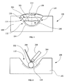
- FIG. 1 shows an exemplary component 100 fabricated by an exemplary process.
- the component 100 is a welded component and includes a boundary region 205 formed by a boundary application layer 102 (see FIG. 3 ) positioned at least partially on a crack sensitive fusion boundary 104 of a base metal 105 and a filler region 106 positioned at least partially on the boundary region 205.
- the boundary region 205 provides resistance to strain age cracking within the crack sensitive fusion boundary 104.
- the term "crack sensitive fusion boundary” refers to a region of a component with heightened sensitivity to cracking in comparison to other regions, for example, due to casting dilution effect. For example, as shown in FIG.
- the crack sensitive fusion boundary 104 extends below a base 101 of an isosceles triangle 108 formed within a semicircular or semispherical cavity 110 of the component 100. In one embodiment, the crack sensitive fusion boundary 104 is within a lower portion 112 of the cavity 110, for example, about 1/3 of the depth of the cavity 110, and/or is not within the upper portion 114 of the cavity 110.
- the cavity 110 includes alternative geometries including, but not limited to, a curved geometry that is not a semicircular or semispherical, channel-like geometry, a rectilinear geometry, a complex geometry (for example, turbine components such as blades, nozzles, shrouds, and other complex components), or any other suitable geometry.
- a curved geometry that is not a semicircular or semispherical, channel-like geometry, a rectilinear geometry, a complex geometry (for example, turbine components such as blades, nozzles, shrouds, and other complex components), or any other suitable geometry.
- the component 100 is fabricated by depositing (for example, pre-dripping) and then manipulating (for example, smearing, buttering, or otherwise manipulating) a molten material 202 onto at least a portion of a surface 204 of the component 100 to form the boundary application layer 102 and then the boundary region 205 (see FIG. 4 ).
- the molten material 202 is applied in conjunction with a weld torch 208 and a weld rod 209.
- Welding according to the disclosure is performed by any suitable weld mechanism/process, including, but not limited to plasma weld processes, arc weld processes, laser or pulse weld processes, tungsten inert gas weld processes, other suitable weld processes, or combinations thereof.
- suitable weld mechanism/process including, but not limited to plasma weld processes, arc weld processes, laser or pulse weld processes, tungsten inert gas weld processes, other suitable weld processes, or combinations thereof.
- the weld rod 209 is one or more alloys capable of being melted by the weld torch 208.
- the weld rod 209 is capable of being in the form of a rod or any other suitable shape (such as a twisted rod) capable of being melted by the weld torch 208.
- depositing the molten material 202 according to the process increases resistance to melt pool turbulence, increases resistance to dilution of the base metal 105, decreases heat input used, increases resistance to liquation and strain age cracking, decreases reliance upon and/or replaces heat treatment utilized after welding, and combinations thereof.
- the molten material 202 is applied without localized melting of the base metal 105.
- the base metal 105 and/or the molten material 202 include a superalloy material.
- a superalloy material is a nickel-based alloy having, by weight, up to about 15% chromium, up to about 10% cobalt, up to about 4% tungsten, up to about 2% molybdenum, up to about 5% titanium, up to about 3% aluminum, and up to about 3% tantalum.
- the superalloy material has a composition by weight of about 14% chromium, about 9.5% cobalt, about 3.8% tungsten, about 1.5% molybdenum, about 4.9% titanium, about 3.0% aluminum, about 0.1% carbon, about 0.01% boron, about 2.8% tantalum, and a balance of nickel.
- One suitable superalloy material is a nickel-based alloy having, by weight, up to about 10% chromium, up to about 8% cobalt, up to about 4% titanium, up to about 5% aluminum, up to about 6% tungsten, and up to about 5% tantalum.
- the superalloy material has a composition, by weight, of about 9.75% chromium, about 7.5% cobalt, about 3.5% titanium, about 4.2% aluminum, about 6.0% tungsten, about 1.5% molybdenum, about 4.8% tantalum, about 0.08% carbon, about 0.009% zirconium, about 0.009% boron, and a balance of nickel.
- One suitable superalloy material is a nickel-based alloy having, by weight, up to about 8% cobalt, up to about 7 chromium, up to about 6% tantalum, up to about 7% aluminum, up to about 5% tungsten, up to about 3% rhenium and up to about 2% molybdenum.
- the superalloy material has a composition, by weight, of about 7.5% cobalt, about 7.0% chromium, about 6.5% tantalum, about 6.2% aluminum, about 5.0% tungsten, about 3.0% rhenium, about 1.5% molybdenum, about 0.15% hafnium, about 0.05% carbon, about 0.004% boron, about 0.01% yttrium, and a balance of nickel.
- One suitable superalloy material is a nickel-based alloy having, by weight, up to about 10% chromium, up to about 8% cobalt, up to about 5% aluminum, up to about 4% titanium, up to about 2% molybdenum, up to about 6% tungsten and up to about 5% tantalum.
- the superalloy material has a composition, by weight, of about 9.75% chromium, about 7.5% cobalt, about 4.2% aluminum, about 3.5% titanium, about 1.5% molybdenum, about 6.0% tungsten, about 4.8% tantalum, about 0.5% niobium, about 0.15% hafnium, about 0.05% carbon, about 0.004% boron, and a balance of nickel.
- One suitable superalloy material is a nickel-based alloy having, by weight, up to about 10% cobalt, up to about 8% chromium, up to about 10% tungsten, up to about 6% aluminum, up to about 3% tantalum and up to about 2% hafnium.
- the superalloy material has a composition, by weight, of about 9.5% cobalt, about 8.0% chromium, about 9.5% tungsten, about 0.5% molybdenum, about 5.5% aluminum, about 0.8% titanium, about 3.0% tantalum, about 0.1% zirconium, about 1.0% carbon, about 0.15% hafnium and a balance of nickel.
- the superalloy material is capable of resisting predetermined temperatures, for example, temperatures of a hot gas path in a gas turbine.
- a first portion of the superalloy material is resistant to heat above a first/higher temperature, for example, about 1000°F, about 1250°F, about 1500°F, about 2000°F, or about 2200°F
- a second portion of the superalloy material is resistant to heat above a second/lower temperature, for example, between 800°F and 1250°F, about 800°F, about 1000°F, about 1250°F, about 1500°F, or about 2000°F.
- the molten material 202 is applied within a predetermined range of current, for example, between about 5A and about 40A, between about 5A and about 10A, or between about 30A and about 40A.
- the composition of the molten material 202 is the same as the base metal 105.
- the composition of the molten material 202 differs from the base metal 105.
- the molten material 202 and the base metal 105 are superalloys selected from the compositions discussed above.
- the molten material 202 is applied with a predetermined size.
- the predetermined size is based upon dimensions of the weld rod 209.
- the molten material 202 upon being applied, generally forms a sphere having about 1.5 to 2.0 times a diameter in comparison to the diameter of the weld rod 209.
- the diameter of the weld rod is about between 15 thousandths of an inch and 45 thousandths of an inch, or between about 25 thousandths of an inch and 35 thousandths of an inch, or at about 30 thousandths of an inch.
- the molten material 202 is separately formed into spheres or other particles having the predetermined size apart from the application process.
- the predetermined size is based upon including an amount of the molten material 202 capable of covering a majority or all of the crack sensitive fusion boundary 104. In one embodiment, the predetermined size is based upon the number of layers to be formed. For example, in one embodiment, the predetermined size of the molten material 202 applied is substantially equal to a predetermined volume of the cavity 110. In a further embodiment, the predetermined volume is the volume of the cavity 110 proximal to the crack sensitive fusion boundary 104.
- the boundary application layer 102 is at least partially solidified upon contacting the base metal 105. Upon being at least partially solidified, the boundary application layer 102 is spread, buttered, or otherwise manipulated and/or deposited to form the boundary region 205 (see FIGS. 1 and 4 ). For example, in one embodiment, the boundary region 205 is buttered to cover all or at least a portion of the crack sensitive fusion boundary 104 of the base metal 105. A filler region 206 is then formed on the boundary region 205.
- the molten material 202 is applied to form one or more molten material application layers 207 until the filler region 206 is formed.
- the one or more molten material application layers 207 include the same material as the base metal 105, the same material as the molten material 202 in the boundary region 205, any suitable superalloy (including those disclosed above), or any combination thereof.
- the component 100 is formed by depositing a first application of the molten material 202 onto a surface within the cavity 110 of the base metal 105 where the first application of the molten material 202 at least partially solidifies (see FIG. 2 ). In one embodiment, the molten material 202 fully solidifies. The method continues with the melting of at least a portion of partially solidified material. This portion is then manipulated to form the boundary region 205 (see FIG. 3 ). A second application of the molten material 202, which may or may not include the same composition as the first application of the molten material 202, is then deposited onto the boundary region 205 as a first molten material application layer 207 (see FIG. 4 ).
- the first molten material application layer 207 is then manipulated to form the filler region 206 (see FIG. 5 ).
- a third application of the molten material 202 which may or may not include the same composition as the first application of the molten material 202 and/or the second application of the molten material 202, is then deposited onto the filler region 206 as a second molten material application layer 207 (see FIG. 6 ).
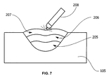
- the second molten material application layer 207 is then manipulated to further form filler region 206 (see FIG. 7 ).
- a surface layer 211 which may or may not include the same composition as the first application of the molten material 202, the second application of the molten material 202, the third application of the molten material 202, the base metal 105, or any other suitable composition, is applied to the filler region 206, thereby forming the component 100 (see FIG. 1 ).
- a fourth, fifth, sixth, or greater number of the molten material application layers 207 may be applied and manipulated to further form the filler region 206.
- the base metal includes a composition, by weight, of about 8.0% to about 8.7% chromium, about 9.0% to about 10.0% cobalt, about 5.25% to about 5.75% aluminum, about 0.60% to about 0.90% titanium, 9.30% to about 9.70% tungsten, about 0.40% to about 0.60% molybdenum, about 2.80% to about 3.30% tantalum, and a balance of nickel and the molten material 202 (forming the boundary region 205 and/or the molten material application layer(s) 207) includes a composition, by weight, of about 19.0% to about 21.0% chromium, about 19.0% to about 21.0% cobalt, about 0.30% to about 0.60% aluminum, about 1.90% to about 2.40% titanium, about 5.60% to about 6.10% molybdenum, about 2.40% to about 2.80% tantalum + Aluminum, and a balance of nickel.
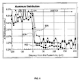
- an aluminum distribution 802 corresponding to the present disclosure is lower within the boundary region 205 and/or the molten material application layer(s) 207 than a first non-drip weld process aluminum distribution 804 or a second non-drip weld process aluminum distribution 806.
- the exemplary aluminum distribution 802 is lower within the boundary region 205 and/or the molten material application layer(s) 207 than a first non-drip weld process aluminum distribution 804 or a second non-drip weld process aluminum distribution 806.
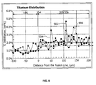
- the exemplary titanium distribution 902 is higher within the boundary region 205 and/or the molten material application layer(s) 207 than a first non-drip weld process titanium distribution 904 or a second non-drip weld process titanium distribution 906.
Landscapes
- Engineering & Computer Science (AREA)
- Mechanical Engineering (AREA)
- Physics & Mathematics (AREA)
- Plasma & Fusion (AREA)
- Optics & Photonics (AREA)
- Chemical & Material Sciences (AREA)
- Materials Engineering (AREA)
- Metallurgy (AREA)
- Organic Chemistry (AREA)
- Turbine Rotor Nozzle Sealing (AREA)
Abstract
Description
- The present invention is directed to manufactured components and processes of fabricating manufactured components. In particular, the present invention is directed to processes for welding and welded components.
- The operating temperature within a gas turbine is both thermally and chemically hostile. Advances in high temperature capabilities have been achieved through the development of iron, nickel, and cobalt-based superalloys and the use of environmental coatings capable of protecting superalloys from oxidation, hot corrosion, etc.
- In the compressor portion of a gas turbine, atmospheric air is compressed to 10-25 times atmospheric pressure, and adiabatically heated to 700°F - 1250°F (371°C - 677°C) in the process. This heated and compressed air is directed into a combustor, where it is mixed with fuel. The fuel is ignited, and the combustion process heats the gases to very high temperatures, in excess of 3000°F (1650°C). These hot gases pass through the turbine, where airfoils fixed to rotating turbine disks extract energy to drive an attached generator which produces electrical power. To improve the efficiency of operation of the turbine, combustion temperatures have been raised. Of course, as the combustion temperature is raised, steps must be taken to prevent thermal degradation of the materials forming the flow path for these hot gases of combustion.
- Many hot gas path components are fabricated using welding processes. It is desirable for weld joints in or around such components to have increased resistance to strain age cracking, thereby extending the operational range of the components and/or the usable life of the components.
- A welded component and a process of welding a component that do not suffer from one or more of the above drawbacks would be desirable in the art.
- In an exemplary embodiment, a method of fabricating a component includes depositing a first molten material application onto a surface to form an at least partially solidified layer, manipulating at least a portion of the at least partially solidified layer to form a boundary region, and depositing a second molten material application onto the boundary region to form a filler region.
- In another exemplary embodiment, a method of fabricating a component includes depositing a first material onto at least a portion of a crack sensitive fusion boundary of the component, manipulating the material to form a boundary region, and depositing a second material onto the boundary region. The boundary region provides resistance to strain age cracking within the crack sensitive fusion boundary.
- In another exemplary embodiment, a welded component includes a boundary region positioned at least partially on a crack sensitive fusion boundary and a filler region positioned at least partially on the boundary region. The boundary region provides resistance to strain age cracking within the crack sensitive fusion boundary.
-
-
FIG. 1 is a schematic view of an exemplary component according to the disclosure. -
FIG. 2 is a diagrammatic view of an exemplary component having molten material applied according to an exemplary process of the disclosure. -
FIG. 3 is a diagrammatic view of an exemplary melting of material according to an exemplary process of the disclosure. -
FIG. 4 is a diagrammatic view of an exemplary component having molten material applied to a boundary region according to an exemplary process of the disclosure. -
FIG. 5 is a diagrammatic view of an exemplary melting of material applied to a boundary region according to an exemplary process of the disclosure. -
FIG. 6 is a diagrammatic view of an exemplary component having molten material applied according to an exemplary process of the disclosure. -
FIG. 7 is a diagrammatic view of an exemplary melting of material according to an exemplary process of the disclosure. -
FIG. 8 is a graphic view illustrating an aluminum distribution for an exemplary component in comparison to components fabricated without the application and manipulation of molten material according to the disclosure. -
FIG. 9 is a graphic view illustrating a titanium distribution for an exemplary component in comparison to components fabricated without the application and manipulation of molten material according to the disclosure. - Provided is a manufactured component and a process of fabricating a component. Embodiments of the present disclosure have a decreased stress level due to high preheat or very low heat input, have a transition weld deposit resistant to strain age cracking, have increased resistance to crack formation, have lower base metal dilution, permit repair or casting defects, and combinations thereof.
-
FIG. 1 shows anexemplary component 100 fabricated by an exemplary process. Thecomponent 100 is a welded component and includes aboundary region 205 formed by a boundary application layer 102 (seeFIG. 3 ) positioned at least partially on a cracksensitive fusion boundary 104 of abase metal 105 and afiller region 106 positioned at least partially on theboundary region 205. Theboundary region 205 provides resistance to strain age cracking within the cracksensitive fusion boundary 104. As used herein, the term "crack sensitive fusion boundary" refers to a region of a component with heightened sensitivity to cracking in comparison to other regions, for example, due to casting dilution effect. For example, as shown inFIG. 1 , in one embodiment, the cracksensitive fusion boundary 104 extends below abase 101 of anisosceles triangle 108 formed within a semicircular orsemispherical cavity 110 of thecomponent 100. In one embodiment, the cracksensitive fusion boundary 104 is within alower portion 112 of thecavity 110, for example, about 1/3 of the depth of thecavity 110, and/or is not within theupper portion 114 of thecavity 110. As will be appreciated, in some embodiments, thecavity 110 includes alternative geometries including, but not limited to, a curved geometry that is not a semicircular or semispherical, channel-like geometry, a rectilinear geometry, a complex geometry (for example, turbine components such as blades, nozzles, shrouds, and other complex components), or any other suitable geometry. - As shown in
FIGS. 2 and3 , according to the exemplary process, thecomponent 100 is fabricated by depositing (for example, pre-dripping) and then manipulating (for example, smearing, buttering, or otherwise manipulating) amolten material 202 onto at least a portion of asurface 204 of thecomponent 100 to form theboundary application layer 102 and then the boundary region 205 (seeFIG. 4 ). In one embodiment, themolten material 202 is applied in conjunction with aweld torch 208 and aweld rod 209. Welding according to the disclosure is performed by any suitable weld mechanism/process, including, but not limited to plasma weld processes, arc weld processes, laser or pulse weld processes, tungsten inert gas weld processes, other suitable weld processes, or combinations thereof. - The
weld rod 209 is one or more alloys capable of being melted by theweld torch 208. Theweld rod 209 is capable of being in the form of a rod or any other suitable shape (such as a twisted rod) capable of being melted by theweld torch 208. In one embodiment, depositing themolten material 202 according to the process increases resistance to melt pool turbulence, increases resistance to dilution of thebase metal 105, decreases heat input used, increases resistance to liquation and strain age cracking, decreases reliance upon and/or replaces heat treatment utilized after welding, and combinations thereof. In one embodiment, themolten material 202 is applied without localized melting of thebase metal 105. - The
base metal 105 and/or themolten material 202 include a superalloy material. One suitable superalloy material is a nickel-based alloy having, by weight, up to about 15% chromium, up to about 10% cobalt, up to about 4% tungsten, up to about 2% molybdenum, up to about 5% titanium, up to about 3% aluminum, and up to about 3% tantalum. In one embodiment, the superalloy material has a composition by weight of about 14% chromium, about 9.5% cobalt, about 3.8% tungsten, about 1.5% molybdenum, about 4.9% titanium, about 3.0% aluminum, about 0.1% carbon, about 0.01% boron, about 2.8% tantalum, and a balance of nickel. - One suitable superalloy material is a nickel-based alloy having, by weight, up to about 10% chromium, up to about 8% cobalt, up to about 4% titanium, up to about 5% aluminum, up to about 6% tungsten, and up to about 5% tantalum. In one embodiment, the superalloy material has a composition, by weight, of about 9.75% chromium, about 7.5% cobalt, about 3.5% titanium, about 4.2% aluminum, about 6.0% tungsten, about 1.5% molybdenum, about 4.8% tantalum, about 0.08% carbon, about 0.009% zirconium, about 0.009% boron, and a balance of nickel.
- One suitable superalloy material is a nickel-based alloy having, by weight, up to about 8% cobalt, up to about 7 chromium, up to about 6% tantalum, up to about 7% aluminum, up to about 5% tungsten, up to about 3% rhenium and up to about 2% molybdenum. In one embodiment, the superalloy material has a composition, by weight, of about 7.5% cobalt, about 7.0% chromium, about 6.5% tantalum, about 6.2% aluminum, about 5.0% tungsten, about 3.0% rhenium, about 1.5% molybdenum, about 0.15% hafnium, about 0.05% carbon, about 0.004% boron, about 0.01% yttrium, and a balance of nickel.
- One suitable superalloy material is a nickel-based alloy having, by weight, up to about 10% chromium, up to about 8% cobalt, up to about 5% aluminum, up to about 4% titanium, up to about 2% molybdenum, up to about 6% tungsten and up to about 5% tantalum. In one embodiment, the superalloy material has a composition, by weight, of about 9.75% chromium, about 7.5% cobalt, about 4.2% aluminum, about 3.5% titanium, about 1.5% molybdenum, about 6.0% tungsten, about 4.8% tantalum, about 0.5% niobium, about 0.15% hafnium, about 0.05% carbon, about 0.004% boron, and a balance of nickel.
- One suitable superalloy material is a nickel-based alloy having, by weight, up to about 10% cobalt, up to about 8% chromium, up to about 10% tungsten, up to about 6% aluminum, up to about 3% tantalum and up to about 2% hafnium. In one embodiment, the superalloy material has a composition, by weight, of about 9.5% cobalt, about 8.0% chromium, about 9.5% tungsten, about 0.5% molybdenum, about 5.5% aluminum, about 0.8% titanium, about 3.0% tantalum, about 0.1% zirconium, about 1.0% carbon, about 0.15% hafnium and a balance of nickel.
- The superalloy material is capable of resisting predetermined temperatures, for example, temperatures of a hot gas path in a gas turbine. For example, in one embodiment, a first portion of the superalloy material is resistant to heat above a first/higher temperature, for example, about 1000°F, about 1250°F, about 1500°F, about 2000°F, or about 2200°F, and a second portion of the superalloy material is resistant to heat above a second/lower temperature, for example, between 800°F and 1250°F, about 800°F, about 1000°F, about 1250°F, about 1500°F, or about 2000°F.
- Referring to
FIGS. 2-3 , themolten material 202 is applied within a predetermined range of current, for example, between about 5A and about 40A, between about 5A and about 10A, or between about 30A and about 40A. In one embodiment, the composition of themolten material 202 is the same as thebase metal 105. In another embodiment, the composition of themolten material 202 differs from thebase metal 105. In this embodiment, themolten material 202 and thebase metal 105 are superalloys selected from the compositions discussed above. - The
molten material 202 is applied with a predetermined size. The predetermined size is based upon dimensions of theweld rod 209. For example, upon being applied, themolten material 202 generally forms a sphere having about 1.5 to 2.0 times a diameter in comparison to the diameter of theweld rod 209. In one embodiment, the diameter of the weld rod is about between 15 thousandths of an inch and 45 thousandths of an inch, or between about 25 thousandths of an inch and 35 thousandths of an inch, or at about 30 thousandths of an inch. In another embodiment, themolten material 202 is separately formed into spheres or other particles having the predetermined size apart from the application process. - In one embodiment, the predetermined size is based upon including an amount of the
molten material 202 capable of covering a majority or all of the cracksensitive fusion boundary 104. In one embodiment, the predetermined size is based upon the number of layers to be formed. For example, in one embodiment, the predetermined size of themolten material 202 applied is substantially equal to a predetermined volume of thecavity 110. In a further embodiment, the predetermined volume is the volume of thecavity 110 proximal to the cracksensitive fusion boundary 104. - The
boundary application layer 102 is at least partially solidified upon contacting thebase metal 105. Upon being at least partially solidified, theboundary application layer 102 is spread, buttered, or otherwise manipulated and/or deposited to form the boundary region 205 (seeFIGS. 1 and4 ). For example, in one embodiment, theboundary region 205 is buttered to cover all or at least a portion of the cracksensitive fusion boundary 104 of thebase metal 105. Afiller region 206 is then formed on theboundary region 205. - Referring to
FIGS. 4-7 , themolten material 202 is applied to form one or more molten material application layers 207 until thefiller region 206 is formed. The one or more molten material application layers 207 include the same material as thebase metal 105, the same material as themolten material 202 in theboundary region 205, any suitable superalloy (including those disclosed above), or any combination thereof. - In one embodiment, the
component 100 is formed by depositing a first application of themolten material 202 onto a surface within thecavity 110 of thebase metal 105 where the first application of themolten material 202 at least partially solidifies (seeFIG. 2 ). In one embodiment, themolten material 202 fully solidifies. The method continues with the melting of at least a portion of partially solidified material. This portion is then manipulated to form the boundary region 205 (seeFIG. 3 ). A second application of themolten material 202, which may or may not include the same composition as the first application of themolten material 202, is then deposited onto theboundary region 205 as a first molten material application layer 207 (seeFIG. 4 ). The first moltenmaterial application layer 207 is then manipulated to form the filler region 206 (seeFIG. 5 ). In a further embodiment, a third application of themolten material 202, which may or may not include the same composition as the first application of themolten material 202 and/or the second application of themolten material 202, is then deposited onto thefiller region 206 as a second molten material application layer 207 (seeFIG. 6 ). The second moltenmaterial application layer 207 is then manipulated to further form filler region 206 (seeFIG. 7 ). In one embodiment, asurface layer 211, which may or may not include the same composition as the first application of themolten material 202, the second application of themolten material 202, the third application of themolten material 202, thebase metal 105, or any other suitable composition, is applied to thefiller region 206, thereby forming the component 100 (seeFIG. 1 ). Likewise, a fourth, fifth, sixth, or greater number of the molten material application layers 207 may be applied and manipulated to further form thefiller region 206. - Referring to
FIGS. 8 and9 , in one embodiment, the base metal includes a composition, by weight, of about 8.0% to about 8.7% chromium, about 9.0% to about 10.0% cobalt, about 5.25% to about 5.75% aluminum, about 0.60% to about 0.90% titanium, 9.30% to about 9.70% tungsten, about 0.40% to about 0.60% molybdenum, about 2.80% to about 3.30% tantalum, and a balance of nickel and the molten material 202 (forming theboundary region 205 and/or the molten material application layer(s) 207) includes a composition, by weight, of about 19.0% to about 21.0% chromium, about 19.0% to about 21.0% cobalt, about 0.30% to about 0.60% aluminum, about 1.90% to about 2.40% titanium, about 5.60% to about 6.10% molybdenum, about 2.40% to about 2.80% tantalum + Aluminum, and a balance of nickel. In this embodiment, analuminum distribution 802 corresponding to the present disclosure is lower within theboundary region 205 and/or the molten material application layer(s) 207 than a first non-drip weldprocess aluminum distribution 804 or a second non-drip weldprocess aluminum distribution 806. Similarly, theexemplary aluminum distribution 802 is lower within theboundary region 205 and/or the molten material application layer(s) 207 than a first non-drip weldprocess aluminum distribution 804 or a second non-drip weldprocess aluminum distribution 806. Similarly, theexemplary titanium distribution 902 is higher within theboundary region 205 and/or the molten material application layer(s) 207 than a first non-drip weldprocess titanium distribution 904 or a second non-drip weldprocess titanium distribution 906. - While the invention has been described with reference to a preferred embodiment, it will be understood by those skilled in the art that various changes may be made and equivalents may be substituted for elements thereof without departing from the scope of the invention. In addition, many modifications may be made to adapt a particular situation or material to the teachings of the invention without departing from the essential scope thereof. Therefore, it is intended that the invention not be limited to the particular embodiment disclosed as the best mode contemplated for carrying out this invention, but that the invention will include all embodiments falling within the scpe of the appended claims.
Claims (20)
- A method of fabricating a component, comprising:depositing a first molten material application onto a surface to form an at least partially solidified layer;manipulating at least a portion of the at least partially solidified layer to form a boundary region; anddepositing a second molten material application onto the boundary region to form a filler region.
- The method of claim 1, wherein the first molten material application includes substantially the same composition as the second molten material application.
- The method of claim 1, wherein the first molten material application includes a different composition from the second molten material application.
- The method of any preceding claim, further comprising melting the portion of the at least partially solidified layer prior to manipulating the portion to form the boundary region.
- The method of any preceding claim, wherein the component includes a crack sensitive fusion boundary.
- The method of claim 5, wherein the boundary region provides resistance to strain age cracking within a crack sensitive fusion boundary of the component.
- The method of claim 5, wherein the boundary region covers the entire crack sensitive fusion boundary.
- The method of claim 5, wherein the boundary region covers at least a portion of the crack sensitive fusion boundary.
- The method of claim 5, wherein the boundary region fills about 1/3 of the volume of a cavity in the component.
- The method of any preceding claim, wherein one or more of the boundary region and the filler region includes a nickel-based superalloy selected from the group consisting of:a composition, by weight, of about 15% chromium, about 10% cobalt, about 4% tungsten, about 2% molybdenum, about 5% titanium, about 3.% aluminum, and about 0.1% carbon, about 0.01% boron, about 3% tantalum, and a balance of nickel;a composition, by weight, of about 10% chromium, about 8% cobalt, about 4% titanium, about 5% aluminum, about 6% tungsten, about 1.5% molybdenum, about 5% tantalum, about 0.08% carbon, about 0.009% zirconium, about 0.009% boron, and a balance of nickel;a composition, by weight, of about 8% cobalt, about 7% chromium, about 6% tantalum, about 7% aluminum, about 5% tungsten, about 3% rhenium, about 2% molybdenum, about 0.15% hafnium, about 0.05% carbon, about 0.004% boron, about 0.01% yttrium, and a balance of nickel;a composition, by weight, of about 10% chromium, about 8% cobalt, about 5% aluminum, about 4% titanium, about 2% molybdenum, about 6% tungsten, about 5% tantalum, about 0.5% niobium, about 0.15% hafnium, about 0.05% carbon, about 0.004% boron, and a balance of nickel; anda composition, by weight, of about 9.5% cobalt, about 8.0% chromium, about 9.5% tungsten, about 0.5% molybdenum, about 5.5% aluminum, about 0.8% titanium, about 3.0% tantalum, about 0.1% zirconium, about 1.0% carbon, about 0.15% hafnium and a balance of nickel.
- The method of any preceding claim, wherein the first molten material application is applied within a predetermined range of current, the predetermined range being between about 5A and about 40A.
- The method of any preceding claim, further comprising manipulating the second molten material application to further form the filler region.
- The method of claim 12, further comprising depositing a third molten material application to further form the filler region.
- The method of claim 13, further comprising manipulating the third molten material application to further form the filler region.
- The method of any preceding claim, further comprising applying a surface layer to the filler region.
- The method of any preceding claim, further comprising treating the surface prior to depositing the first molten material, the treating being selected from the group consisting of preheating, solution heat treating, overage heat treating, and combinations thereof.
- The method of any preceding claim, wherein the first molten material is formed by a gas tungsten arc welding apparatus or a plasma arc welding apparatus.
- A method of fabricating a component, comprising:depositing a first material onto at least a portion of a crack sensitive fusion boundary of the component;manipulating the first material to form a boundary region; anddepositing a second material onto the boundary region;wherein the boundary region provides resistance to strain age cracking within the crack sensitive fusion boundary.
- A welded component, comprising:a boundary region positioned at least partially on a crack sensitive fusion boundary; anda filler region positioned at least partially on the boundary region;wherein the boundary region provides resistance to strain age cracking within the crack sensitive fusion boundary.
- The component of claim 19, wherein one or more of the boundary region and the filler region includes a nickel-based superalloy selected from the group consisting of:a composition, by weight, of about 14% chromium, about 9.5% cobalt, about 3.8% tungsten, about 1.5% molybdenum, about 4.9% titanium, about 3.0% aluminum, about 0.1% carbon, about 0.01% boron, about 2.8% tantalum, and a balance of nickel;a composition, by weight, of about 9.75% chromium, about 7.5% cobalt, about 3.5% titanium, about 4.2% aluminum, about 6.0% tungsten, about 1.5% molybdenum, about 4.8% tantalum, about 0.08% carbon, about 0.009% zirconium, about 0.009% boron, and a balance of nickel;a composition, by weight, of about 7.5% cobalt, about 7.0% chromium, about 6.5% tantalum, about 6.2% aluminum, about 5.0% tungsten, about 3.0% rhenium, about 1.5% molybdenum, about 0.15% hafnium, about 0.05% carbon, about 0.004% boron, about 0.01% yttrium, and a balance of nickel;a composition, by weight, of about 9.75% chromium, about 7.5% cobalt, about 4.2% aluminum, about 3.5% titanium, about 1.5% molybdenum, about 6.0% tungsten, about 4.8% tantalum, about 0.5% niobium, about 0.15% hafnium, about 0.05% carbon, about 0.004% boron, and a balance of nickel; anda composition, by weight, of about 9.5% cobalt, about 8.0% chromium, about 9.5% tungsten, about 0.5% molybdenum, about 5.5% aluminum, about 0.8% titanium, about 3.0% tantalum, about 0.1% zirconium, about 1.0% carbon, about 0.15% hafnium and a balance of nickel.
Priority Applications (1)
| Application Number | Priority Date | Filing Date | Title |
|---|---|---|---|
| PL12172275T PL2537619T3 (en) | 2011-06-22 | 2012-06-15 | Build-up welding method of fabricating a component and a manufactured component |
Applications Claiming Priority (1)
| Application Number | Priority Date | Filing Date | Title |
|---|---|---|---|
| US13/166,215 US8921730B2 (en) | 2011-06-22 | 2011-06-22 | Method of fabricating a component and a manufactured component |
Publications (2)
| Publication Number | Publication Date |
|---|---|
| EP2537619A1 true EP2537619A1 (en) | 2012-12-26 |
| EP2537619B1 EP2537619B1 (en) | 2020-02-12 |
Family
ID=46319597
Family Applications (1)
| Application Number | Title | Priority Date | Filing Date |
|---|---|---|---|
| EP12172275.5A Active EP2537619B1 (en) | 2011-06-22 | 2012-06-15 | Build-up welding method of fabricating a component and a manufactured component |
Country Status (4)
| Country | Link |
|---|---|
| US (2) | US8921730B2 (en) |
| EP (1) | EP2537619B1 (en) |
| CN (1) | CN102837134B (en) |
| PL (1) | PL2537619T3 (en) |
Cited By (1)
| Publication number | Priority date | Publication date | Assignee | Title |
|---|---|---|---|---|
| WO2015004538A3 (en) * | 2013-06-28 | 2015-07-02 | Saudi Basic Industries Corporation | Multilayer repair of thick wall vessels |
Families Citing this family (9)
| Publication number | Priority date | Publication date | Assignee | Title |
|---|---|---|---|---|
| US9260788B2 (en) * | 2012-10-30 | 2016-02-16 | General Electric Company | Reinforced articles and methods of making the same |
| EP2756907A1 (en) * | 2013-01-21 | 2014-07-23 | Siemens Aktiengesellschaft | Built-up welding with an external thicker outline contour |
| US9278386B1 (en) | 2014-09-04 | 2016-03-08 | General Electric Company | Hole reducing tool |
| US10174617B2 (en) | 2015-12-10 | 2019-01-08 | General Electric Company | Systems and methods for deep tip crack repair |
| GB2558274B (en) * | 2016-12-23 | 2019-04-17 | Caterpillar Shrewsbury Ltd | Method of remanufacturing a cylinder head |
| CN107643199B (en) * | 2017-09-25 | 2019-11-15 | 国网山东省电力公司电力科学研究院 | A method for prefabricating crack defects inside a steel sample |
| CN108913952B (en) * | 2018-07-27 | 2020-04-03 | 南京工程学院 | A kind of superalloy and preparation method thereof |
| US11517969B2 (en) | 2019-01-24 | 2022-12-06 | General Electric Company | Weld-brazing techniques |
| CN116511522B (en) * | 2023-04-25 | 2026-04-03 | 华中科技大学 | A method for laser-directed energy deposition additive manufacturing of metal surfaces |
Citations (5)
| Publication number | Priority date | Publication date | Assignee | Title |
|---|---|---|---|---|
| US4903888A (en) * | 1988-05-05 | 1990-02-27 | Westinghouse Electric Corp. | Turbine system having more failure resistant rotors and repair welding of low alloy ferrous turbine components by controlled weld build-up |
| GB2228224A (en) * | 1989-02-08 | 1990-08-22 | Gen Electric | Fabrication of articles |
| JPH04327371A (en) * | 1991-04-25 | 1992-11-16 | Nippon Kyoryo Kk | Multilayer welding method |
| US20110073636A1 (en) * | 2008-05-29 | 2011-03-31 | Nikolai Arjakine | Method and device for welding workpieces made of high-temperature resistant super Alloys |
| US20110089150A1 (en) * | 2009-10-15 | 2011-04-21 | Nikolai Arjakine | Method and Apparatus for Welding Workpieces of High-Temperature Superalloys |
Family Cites Families (19)
| Publication number | Priority date | Publication date | Assignee | Title |
|---|---|---|---|---|
| US2994762A (en) * | 1959-09-08 | 1961-08-01 | Jess M Roberts | Method of fusing materials to metal surfaces |
| US3277267A (en) * | 1965-09-20 | 1966-10-04 | Blaszkowski Henry | Method and apparatus for treating electrically conductive surfaces |
| US3360630A (en) * | 1966-01-19 | 1967-12-26 | Blaszkowski Henry | Process of hardening metal surfaces |
| DE1615397A1 (en) * | 1967-05-19 | 1970-06-18 | Siemens Ag | Device for automatic spark spraying of thin layers of wear and tear on workpiece surfaces |
| US3778586A (en) * | 1970-04-02 | 1973-12-11 | Composite Sciences | Process for coating metals using resistance heating of preformed layer |
| US4186864A (en) * | 1976-10-29 | 1980-02-05 | Hitachi, Ltd. | Method for producing a welded joint |
| US4346281A (en) * | 1980-01-17 | 1982-08-24 | Inoue-Japax Research Incorporated | Method of and apparatus for discharge-surfacing electrically conductive workpieces |
| US4405851A (en) * | 1981-06-11 | 1983-09-20 | Washington State University Research Foundation, Inc. | Apparatus for transfer of metallic materials by electric discharge |
| US5038014A (en) * | 1989-02-08 | 1991-08-06 | General Electric Company | Fabrication of components by layered deposition |
| US6120624A (en) * | 1998-06-30 | 2000-09-19 | Howmet Research Corporation | Nickel base superalloy preweld heat treatment |
| GB9826728D0 (en) * | 1998-12-04 | 1999-01-27 | Rolls Royce Plc | Method and apparatus for building up a workpiece by deposit welding |
| AU2001243302A1 (en) * | 2000-02-29 | 2001-09-12 | General Electric Company | Nickel base superalloys and turbine components fabricated therefrom |
| GB0208226D0 (en) * | 2002-04-09 | 2002-05-22 | Rolls Royce Plc | Apparatus and method for forming a body |
| CA2440573C (en) * | 2002-12-16 | 2013-06-18 | Howmet Research Corporation | Nickel base superalloy |
| US8266800B2 (en) * | 2003-09-10 | 2012-09-18 | Siemens Energy, Inc. | Repair of nickel-based alloy turbine disk |
| US7371988B2 (en) * | 2004-10-22 | 2008-05-13 | Electric Power Research Institute, Inc. | Methods for extending the life of alloy steel welded joints by elimination and reduction of the HAZ |
| US8715772B2 (en) * | 2005-04-12 | 2014-05-06 | Air Products And Chemicals, Inc. | Thermal deposition coating method |
| US7582843B2 (en) * | 2005-09-13 | 2009-09-01 | Ford Global Technologies, Llc | Method for producing a variable flow of melted material and articles therefrom |
| EP3363923A1 (en) * | 2009-10-20 | 2018-08-22 | Siemens Aktiengesellschaft | Alloy for directional solidification and component made of stem-shaped crystals |
-
2011
- 2011-06-22 US US13/166,215 patent/US8921730B2/en active Active
-
2012
- 2012-06-15 EP EP12172275.5A patent/EP2537619B1/en active Active
- 2012-06-15 PL PL12172275T patent/PL2537619T3/en unknown
- 2012-06-25 CN CN201210209865.XA patent/CN102837134B/en active Active
-
2014
- 2014-10-29 US US14/526,731 patent/US20150056469A1/en not_active Abandoned
Patent Citations (5)
| Publication number | Priority date | Publication date | Assignee | Title |
|---|---|---|---|---|
| US4903888A (en) * | 1988-05-05 | 1990-02-27 | Westinghouse Electric Corp. | Turbine system having more failure resistant rotors and repair welding of low alloy ferrous turbine components by controlled weld build-up |
| GB2228224A (en) * | 1989-02-08 | 1990-08-22 | Gen Electric | Fabrication of articles |
| JPH04327371A (en) * | 1991-04-25 | 1992-11-16 | Nippon Kyoryo Kk | Multilayer welding method |
| US20110073636A1 (en) * | 2008-05-29 | 2011-03-31 | Nikolai Arjakine | Method and device for welding workpieces made of high-temperature resistant super Alloys |
| US20110089150A1 (en) * | 2009-10-15 | 2011-04-21 | Nikolai Arjakine | Method and Apparatus for Welding Workpieces of High-Temperature Superalloys |
Cited By (1)
| Publication number | Priority date | Publication date | Assignee | Title |
|---|---|---|---|---|
| WO2015004538A3 (en) * | 2013-06-28 | 2015-07-02 | Saudi Basic Industries Corporation | Multilayer repair of thick wall vessels |
Also Published As
| Publication number | Publication date |
|---|---|
| EP2537619B1 (en) | 2020-02-12 |
| US8921730B2 (en) | 2014-12-30 |
| CN102837134B (en) | 2017-09-15 |
| PL2537619T3 (en) | 2020-07-13 |
| US20120328902A1 (en) | 2012-12-27 |
| US20150056469A1 (en) | 2015-02-26 |
| CN102837134A (en) | 2012-12-26 |
Similar Documents
| Publication | Publication Date | Title |
|---|---|---|
| US8921730B2 (en) | Method of fabricating a component and a manufactured component | |
| TW527251B (en) | Weld repair of directionally solidified articles | |
| CN106563929B (en) | Repair and manufacture the method and turbine engine components of turbine engine components | |
| US6084196A (en) | Elevated-temperature, plasma-transferred arc welding of nickel-base superalloy articles | |
| EP3010671B1 (en) | Method for producing a three-dimensional article | |
| JP6595593B2 (en) | Method for manufacturing turbine engine component | |
| CN106170368B (en) | Structure for superalloy materials is brazed | |
| EP2753451B1 (en) | Isothermal structural repair of superalloy components including turbine blades | |
| EP1207212B1 (en) | Nickel alloy composition | |
| EP3219434B1 (en) | Repair of superalloys by weld forced crack and braze repair | |
| EP2808113B1 (en) | Hybrid diffusion-brazing process | |
| US8141769B2 (en) | Process for repairing a component comprising a directional microstructure by setting a temperature gradient during the laser heat action, and a component produced by such a process | |
| CN105189931B (en) | Component repair using brazed surface textured superalloy foil | |
| CN104923956A (en) | Weld filler for nickel-base superalloys | |
| US20140248512A1 (en) | Functional based repair of superalloy components | |
| US9186724B2 (en) | Electroslag and electrogas repair of superalloy components | |
| JP6877977B2 (en) | Hybrid articles, methods for forming hybrid articles, and methods for filling openings | |
| JP2018193609A (en) | Hybrid article, method for forming a hybrid article, and method for welding | |
| WO2019014445A1 (en) | Method of repairing an article and associated article | |
| JP2003176727A (en) | Repair method for high-temperature component and repaired high-temperature component | |
| JP2017109239A (en) | Article processing method and article | |
| EP2969380B1 (en) | Method for brazing a rene 80 superalloy substrate | |
| CN105431250B (en) | Superalloy component repair by addition of powdered alloy and flux materials | |
| EP3366415B1 (en) | Method of brazing a treatment area of a load-bearing gas turbine component | |
| JP7076948B2 (en) | Articles, components, and methods of making components |
Legal Events
| Date | Code | Title | Description |
|---|---|---|---|
| PUAI | Public reference made under article 153(3) epc to a published international application that has entered the european phase |
Free format text: ORIGINAL CODE: 0009012 |
|
| AK | Designated contracting states |
Kind code of ref document: A1 Designated state(s): AL AT BE BG CH CY CZ DE DK EE ES FI FR GB GR HR HU IE IS IT LI LT LU LV MC MK MT NL NO PL PT RO RS SE SI SK SM TR |
|
| AX | Request for extension of the european patent |
Extension state: BA ME |
|
| 17P | Request for examination filed |
Effective date: 20130626 |
|
| RBV | Designated contracting states (corrected) |
Designated state(s): AL AT BE BG CH CY CZ DE DK EE ES FI FR GB GR HR HU IE IS IT LI LT LU LV MC MK MT NL NO PL PT RO RS SE SI SK SM TR |
|
| 17Q | First examination report despatched |
Effective date: 20150410 |
|
| STAA | Information on the status of an ep patent application or granted ep patent |
Free format text: STATUS: EXAMINATION IS IN PROGRESS |
|
| REG | Reference to a national code |
Ref country code: DE Ref legal event code: R079 Ref document number: 602012067646 Country of ref document: DE Free format text: PREVIOUS MAIN CLASS: B23K0009040000 Ipc: B23K0026340000 |
|
| RIC1 | Information provided on ipc code assigned before grant |
Ipc: B23K 10/02 20060101ALI20190207BHEP Ipc: B23K 9/235 20060101ALI20190207BHEP Ipc: B23K 26/34 20140101AFI20190207BHEP Ipc: B23K 9/04 20060101ALI20190207BHEP |
|
| GRAP | Despatch of communication of intention to grant a patent |
Free format text: ORIGINAL CODE: EPIDOSNIGR1 |
|
| STAA | Information on the status of an ep patent application or granted ep patent |
Free format text: STATUS: GRANT OF PATENT IS INTENDED |
|
| INTG | Intention to grant announced |
Effective date: 20190320 |
|
| GRAJ | Information related to disapproval of communication of intention to grant by the applicant or resumption of examination proceedings by the epo deleted |
Free format text: ORIGINAL CODE: EPIDOSDIGR1 |
|
| STAA | Information on the status of an ep patent application or granted ep patent |
Free format text: STATUS: EXAMINATION IS IN PROGRESS |
|
| INTC | Intention to grant announced (deleted) | ||
| GRAP | Despatch of communication of intention to grant a patent |
Free format text: ORIGINAL CODE: EPIDOSNIGR1 |
|
| STAA | Information on the status of an ep patent application or granted ep patent |
Free format text: STATUS: GRANT OF PATENT IS INTENDED |
|
| INTG | Intention to grant announced |
Effective date: 20190814 |
|
| GRAS | Grant fee paid |
Free format text: ORIGINAL CODE: EPIDOSNIGR3 |
|
| GRAA | (expected) grant |
Free format text: ORIGINAL CODE: 0009210 |
|
| STAA | Information on the status of an ep patent application or granted ep patent |
Free format text: STATUS: THE PATENT HAS BEEN GRANTED |
|
| AK | Designated contracting states |
Kind code of ref document: B1 Designated state(s): AL AT BE BG CH CY CZ DE DK EE ES FI FR GB GR HR HU IE IS IT LI LT LU LV MC MK MT NL NO PL PT RO RS SE SI SK SM TR |
|
| REG | Reference to a national code |
Ref country code: GB Ref legal event code: FG4D |
|
| REG | Reference to a national code |
Ref country code: CH Ref legal event code: EP |
|
| REG | Reference to a national code |
Ref country code: AT Ref legal event code: REF Ref document number: 1231454 Country of ref document: AT Kind code of ref document: T Effective date: 20200215 |
|
| REG | Reference to a national code |
Ref country code: IE Ref legal event code: FG4D |
|
| REG | Reference to a national code |
Ref country code: DE Ref legal event code: R096 Ref document number: 602012067646 Country of ref document: DE |
|
| PG25 | Lapsed in a contracting state [announced via postgrant information from national office to epo] |
Ref country code: NO Free format text: LAPSE BECAUSE OF FAILURE TO SUBMIT A TRANSLATION OF THE DESCRIPTION OR TO PAY THE FEE WITHIN THE PRESCRIBED TIME-LIMIT Effective date: 20200512 Ref country code: FI Free format text: LAPSE BECAUSE OF FAILURE TO SUBMIT A TRANSLATION OF THE DESCRIPTION OR TO PAY THE FEE WITHIN THE PRESCRIBED TIME-LIMIT Effective date: 20200212 Ref country code: RS Free format text: LAPSE BECAUSE OF FAILURE TO SUBMIT A TRANSLATION OF THE DESCRIPTION OR TO PAY THE FEE WITHIN THE PRESCRIBED TIME-LIMIT Effective date: 20200212 |
|
| REG | Reference to a national code |
Ref country code: LT Ref legal event code: MG4D |
|
| REG | Reference to a national code |
Ref country code: NL Ref legal event code: MP Effective date: 20200212 |
|
| PG25 | Lapsed in a contracting state [announced via postgrant information from national office to epo] |
Ref country code: GR Free format text: LAPSE BECAUSE OF FAILURE TO SUBMIT A TRANSLATION OF THE DESCRIPTION OR TO PAY THE FEE WITHIN THE PRESCRIBED TIME-LIMIT Effective date: 20200513 Ref country code: IS Free format text: LAPSE BECAUSE OF FAILURE TO SUBMIT A TRANSLATION OF THE DESCRIPTION OR TO PAY THE FEE WITHIN THE PRESCRIBED TIME-LIMIT Effective date: 20200612 Ref country code: BG Free format text: LAPSE BECAUSE OF FAILURE TO SUBMIT A TRANSLATION OF THE DESCRIPTION OR TO PAY THE FEE WITHIN THE PRESCRIBED TIME-LIMIT Effective date: 20200512 Ref country code: SE Free format text: LAPSE BECAUSE OF FAILURE TO SUBMIT A TRANSLATION OF THE DESCRIPTION OR TO PAY THE FEE WITHIN THE PRESCRIBED TIME-LIMIT Effective date: 20200212 Ref country code: LV Free format text: LAPSE BECAUSE OF FAILURE TO SUBMIT A TRANSLATION OF THE DESCRIPTION OR TO PAY THE FEE WITHIN THE PRESCRIBED TIME-LIMIT Effective date: 20200212 Ref country code: HR Free format text: LAPSE BECAUSE OF FAILURE TO SUBMIT A TRANSLATION OF THE DESCRIPTION OR TO PAY THE FEE WITHIN THE PRESCRIBED TIME-LIMIT Effective date: 20200212 |
|
| PG25 | Lapsed in a contracting state [announced via postgrant information from national office to epo] |
Ref country code: NL Free format text: LAPSE BECAUSE OF FAILURE TO SUBMIT A TRANSLATION OF THE DESCRIPTION OR TO PAY THE FEE WITHIN THE PRESCRIBED TIME-LIMIT Effective date: 20200212 |
|
| PG25 | Lapsed in a contracting state [announced via postgrant information from national office to epo] |
Ref country code: ES Free format text: LAPSE BECAUSE OF FAILURE TO SUBMIT A TRANSLATION OF THE DESCRIPTION OR TO PAY THE FEE WITHIN THE PRESCRIBED TIME-LIMIT Effective date: 20200212 Ref country code: PT Free format text: LAPSE BECAUSE OF FAILURE TO SUBMIT A TRANSLATION OF THE DESCRIPTION OR TO PAY THE FEE WITHIN THE PRESCRIBED TIME-LIMIT Effective date: 20200705 Ref country code: DK Free format text: LAPSE BECAUSE OF FAILURE TO SUBMIT A TRANSLATION OF THE DESCRIPTION OR TO PAY THE FEE WITHIN THE PRESCRIBED TIME-LIMIT Effective date: 20200212 Ref country code: SK Free format text: LAPSE BECAUSE OF FAILURE TO SUBMIT A TRANSLATION OF THE DESCRIPTION OR TO PAY THE FEE WITHIN THE PRESCRIBED TIME-LIMIT Effective date: 20200212 Ref country code: SM Free format text: LAPSE BECAUSE OF FAILURE TO SUBMIT A TRANSLATION OF THE DESCRIPTION OR TO PAY THE FEE WITHIN THE PRESCRIBED TIME-LIMIT Effective date: 20200212 Ref country code: EE Free format text: LAPSE BECAUSE OF FAILURE TO SUBMIT A TRANSLATION OF THE DESCRIPTION OR TO PAY THE FEE WITHIN THE PRESCRIBED TIME-LIMIT Effective date: 20200212 Ref country code: CZ Free format text: LAPSE BECAUSE OF FAILURE TO SUBMIT A TRANSLATION OF THE DESCRIPTION OR TO PAY THE FEE WITHIN THE PRESCRIBED TIME-LIMIT Effective date: 20200212 Ref country code: LT Free format text: LAPSE BECAUSE OF FAILURE TO SUBMIT A TRANSLATION OF THE DESCRIPTION OR TO PAY THE FEE WITHIN THE PRESCRIBED TIME-LIMIT Effective date: 20200212 Ref country code: RO Free format text: LAPSE BECAUSE OF FAILURE TO SUBMIT A TRANSLATION OF THE DESCRIPTION OR TO PAY THE FEE WITHIN THE PRESCRIBED TIME-LIMIT Effective date: 20200212 |
|
| REG | Reference to a national code |
Ref country code: DE Ref legal event code: R097 Ref document number: 602012067646 Country of ref document: DE |
|
| REG | Reference to a national code |
Ref country code: AT Ref legal event code: MK05 Ref document number: 1231454 Country of ref document: AT Kind code of ref document: T Effective date: 20200212 |
|
| PLBE | No opposition filed within time limit |
Free format text: ORIGINAL CODE: 0009261 |
|
| STAA | Information on the status of an ep patent application or granted ep patent |
Free format text: STATUS: NO OPPOSITION FILED WITHIN TIME LIMIT |
|
| 26N | No opposition filed |
Effective date: 20201113 |
|
| PG25 | Lapsed in a contracting state [announced via postgrant information from national office to epo] |
Ref country code: IT Free format text: LAPSE BECAUSE OF FAILURE TO SUBMIT A TRANSLATION OF THE DESCRIPTION OR TO PAY THE FEE WITHIN THE PRESCRIBED TIME-LIMIT Effective date: 20200212 Ref country code: MC Free format text: LAPSE BECAUSE OF FAILURE TO SUBMIT A TRANSLATION OF THE DESCRIPTION OR TO PAY THE FEE WITHIN THE PRESCRIBED TIME-LIMIT Effective date: 20200212 Ref country code: AT Free format text: LAPSE BECAUSE OF FAILURE TO SUBMIT A TRANSLATION OF THE DESCRIPTION OR TO PAY THE FEE WITHIN THE PRESCRIBED TIME-LIMIT Effective date: 20200212 |
|
| REG | Reference to a national code |
Ref country code: CH Ref legal event code: PL |
|
| PG25 | Lapsed in a contracting state [announced via postgrant information from national office to epo] |
Ref country code: SI Free format text: LAPSE BECAUSE OF FAILURE TO SUBMIT A TRANSLATION OF THE DESCRIPTION OR TO PAY THE FEE WITHIN THE PRESCRIBED TIME-LIMIT Effective date: 20200212 |
|
| PG25 | Lapsed in a contracting state [announced via postgrant information from national office to epo] |
Ref country code: LU Free format text: LAPSE BECAUSE OF NON-PAYMENT OF DUE FEES Effective date: 20200615 |
|
| REG | Reference to a national code |
Ref country code: BE Ref legal event code: MM Effective date: 20200630 |
|
| PG25 | Lapsed in a contracting state [announced via postgrant information from national office to epo] |
Ref country code: IE Free format text: LAPSE BECAUSE OF NON-PAYMENT OF DUE FEES Effective date: 20200615 Ref country code: LI Free format text: LAPSE BECAUSE OF NON-PAYMENT OF DUE FEES Effective date: 20200630 Ref country code: CH Free format text: LAPSE BECAUSE OF NON-PAYMENT OF DUE FEES Effective date: 20200630 |
|
| PG25 | Lapsed in a contracting state [announced via postgrant information from national office to epo] |
Ref country code: BE Free format text: LAPSE BECAUSE OF NON-PAYMENT OF DUE FEES Effective date: 20200630 |
|
| PG25 | Lapsed in a contracting state [announced via postgrant information from national office to epo] |
Ref country code: TR Free format text: LAPSE BECAUSE OF FAILURE TO SUBMIT A TRANSLATION OF THE DESCRIPTION OR TO PAY THE FEE WITHIN THE PRESCRIBED TIME-LIMIT Effective date: 20200212 Ref country code: MT Free format text: LAPSE BECAUSE OF FAILURE TO SUBMIT A TRANSLATION OF THE DESCRIPTION OR TO PAY THE FEE WITHIN THE PRESCRIBED TIME-LIMIT Effective date: 20200212 Ref country code: CY Free format text: LAPSE BECAUSE OF FAILURE TO SUBMIT A TRANSLATION OF THE DESCRIPTION OR TO PAY THE FEE WITHIN THE PRESCRIBED TIME-LIMIT Effective date: 20200212 |
|
| PG25 | Lapsed in a contracting state [announced via postgrant information from national office to epo] |
Ref country code: MK Free format text: LAPSE BECAUSE OF FAILURE TO SUBMIT A TRANSLATION OF THE DESCRIPTION OR TO PAY THE FEE WITHIN THE PRESCRIBED TIME-LIMIT Effective date: 20200212 Ref country code: AL Free format text: LAPSE BECAUSE OF FAILURE TO SUBMIT A TRANSLATION OF THE DESCRIPTION OR TO PAY THE FEE WITHIN THE PRESCRIBED TIME-LIMIT Effective date: 20200212 |
|
| REG | Reference to a national code |
Ref country code: DE Ref legal event code: R082 Ref document number: 602012067646 Country of ref document: DE Ref country code: DE Ref legal event code: R081 Ref document number: 602012067646 Country of ref document: DE Owner name: GENERAL ELECTRIC TECHNOLOGY GMBH, CH Free format text: FORMER OWNER: GENERAL ELECTRIC CO., SCHENECTADY, N.Y., US |
|
| REG | Reference to a national code |
Ref country code: GB Ref legal event code: 732E Free format text: REGISTERED BETWEEN 20240222 AND 20240228 |
|
| PGFP | Annual fee paid to national office [announced via postgrant information from national office to epo] |
Ref country code: PL Payment date: 20250520 Year of fee payment: 14 Ref country code: DE Payment date: 20250520 Year of fee payment: 14 |
|
| PGFP | Annual fee paid to national office [announced via postgrant information from national office to epo] |
Ref country code: GB Payment date: 20250520 Year of fee payment: 14 |
|
| PGFP | Annual fee paid to national office [announced via postgrant information from national office to epo] |
Ref country code: FR Payment date: 20250520 Year of fee payment: 14 |