EP2536999B1 - Fault tolerant vessel stabiliser control system - Google Patents
Fault tolerant vessel stabiliser control system Download PDFInfo
- Publication number
- EP2536999B1 EP2536999B1 EP11744194.9A EP11744194A EP2536999B1 EP 2536999 B1 EP2536999 B1 EP 2536999B1 EP 11744194 A EP11744194 A EP 11744194A EP 2536999 B1 EP2536999 B1 EP 2536999B1
- Authority
- EP
- European Patent Office
- Prior art keywords
- control
- precession
- gyrostabiliser
- vessel
- stabiliser
- Prior art date
- Legal status (The legal status is an assumption and is not a legal conclusion. Google has not performed a legal analysis and makes no representation as to the accuracy of the status listed.)
- Active
Links
- 239000003381 stabilizer Substances 0.000 title claims description 49
- 230000033001 locomotion Effects 0.000 claims description 137
- 230000003019 stabilising effect Effects 0.000 claims description 57
- 238000000034 method Methods 0.000 claims description 44
- 238000013016 damping Methods 0.000 claims description 25
- 238000004886 process control Methods 0.000 claims description 22
- 230000003044 adaptive effect Effects 0.000 claims description 15
- 230000005284 excitation Effects 0.000 claims description 7
- 238000013461 design Methods 0.000 claims description 5
- 239000012530 fluid Substances 0.000 description 15
- 238000005096 rolling process Methods 0.000 description 7
- 230000001276 controlling effect Effects 0.000 description 5
- 238000001514 detection method Methods 0.000 description 5
- 230000001133 acceleration Effects 0.000 description 4
- 230000009471 action Effects 0.000 description 4
- 230000008901 benefit Effects 0.000 description 3
- 238000010586 diagram Methods 0.000 description 3
- 239000011888 foil Substances 0.000 description 3
- 238000013459 approach Methods 0.000 description 2
- 238000013528 artificial neural network Methods 0.000 description 2
- 230000000694 effects Effects 0.000 description 2
- 238000005259 measurement Methods 0.000 description 2
- 239000003921 oil Substances 0.000 description 2
- 230000009467 reduction Effects 0.000 description 2
- 230000002238 attenuated effect Effects 0.000 description 1
- 230000008859 change Effects 0.000 description 1
- 238000011217 control strategy Methods 0.000 description 1
- 238000006073 displacement reaction Methods 0.000 description 1
- 230000007717 exclusion Effects 0.000 description 1
- 238000001914 filtration Methods 0.000 description 1
- 239000010720 hydraulic oil Substances 0.000 description 1
- 239000012535 impurity Substances 0.000 description 1
- 238000004519 manufacturing process Methods 0.000 description 1
- 238000012986 modification Methods 0.000 description 1
- 230000004048 modification Effects 0.000 description 1
- 230000008569 process Effects 0.000 description 1
- 230000001105 regulatory effect Effects 0.000 description 1
- 238000013468 resource allocation Methods 0.000 description 1
- 238000003860 storage Methods 0.000 description 1
Images


Classifications
-
- B—PERFORMING OPERATIONS; TRANSPORTING
- B63—SHIPS OR OTHER WATERBORNE VESSELS; RELATED EQUIPMENT
- B63B—SHIPS OR OTHER WATERBORNE VESSELS; EQUIPMENT FOR SHIPPING
- B63B39/00—Equipment to decrease pitch, roll, or like unwanted vessel movements; Apparatus for indicating vessel attitude
- B63B39/04—Equipment to decrease pitch, roll, or like unwanted vessel movements; Apparatus for indicating vessel attitude to decrease vessel movements by using gyroscopes directly
-
- G—PHYSICS
- G01—MEASURING; TESTING
- G01C—MEASURING DISTANCES, LEVELS OR BEARINGS; SURVEYING; NAVIGATION; GYROSCOPIC INSTRUMENTS; PHOTOGRAMMETRY OR VIDEOGRAMMETRY
- G01C21/00—Navigation; Navigational instruments not provided for in groups G01C1/00 - G01C19/00
- G01C21/10—Navigation; Navigational instruments not provided for in groups G01C1/00 - G01C19/00 by using measurements of speed or acceleration
- G01C21/12—Navigation; Navigational instruments not provided for in groups G01C1/00 - G01C19/00 by using measurements of speed or acceleration executed aboard the object being navigated; Dead reckoning
- G01C21/16—Navigation; Navigational instruments not provided for in groups G01C1/00 - G01C19/00 by using measurements of speed or acceleration executed aboard the object being navigated; Dead reckoning by integrating acceleration or speed, i.e. inertial navigation
- G01C21/18—Stabilised platforms, e.g. by gyroscope
-
- G—PHYSICS
- G05—CONTROLLING; REGULATING
- G05D—SYSTEMS FOR CONTROLLING OR REGULATING NON-ELECTRIC VARIABLES
- G05D1/00—Control of position, course or altitude of land, water, air, or space vehicles, e.g. automatic pilot
- G05D1/08—Control of attitude, i.e. control of roll, pitch, or yaw
- G05D1/0875—Control of attitude, i.e. control of roll, pitch, or yaw specially adapted to water vehicles
Definitions
- the present invention relates to a control system and method for stabilising marine vessel motion induced by excitation wave forces that produce roll motion and relates particularly, though not exclusively, to such a system and method which includes a gyrostabiliser and employs several control modes to provide fault tolerant control.
- the rolling motion of the vessel induces flywheel precession that in turn produces a torque that opposes the rolling motion.
- the induced flywheel precession is always in an appropriate phase to attenuate rolling motion (if the precession does not exceed 90°).
- the induced precession torque will cause the flywheel to precess through more than 90° (over-precess). This causes instability in the roll resisting torque produced by the flywheel as it momentarily becomes zero.
- Gyrostabilisers have particular benefits for applications where the vessel has zero or low forward speed, when hydrodynamics based systems have little or no effect.
- Several applications including, but not limited to, patrol boats, luxury motor yachts, offshore floating production systems and offshore work boats all have significant operational roles at low or zero speed. These applications are driving renewed interest in revisiting gyrostabilisers for controlling wave induced ship rolling motion.
- WO 2009/049371 discloses a method of stabilising an oscillating motion of a vessel by actively controlling precession by applying a braking torque when precession exceeds a threshold.
- WO 2006/058372 discloses gyroscope control of vessel motion wherein the gyroscope is mounted on a rail system to enable athwart the vessel to provide a reactive torque to counter heeling motion generated by a gust of wind.
- WO 2009/009074 discloses control system architecture and algorithm to manage a gyrostabilization system for a marine craft.
- US 2005/274210 is directed to a flywheel spin rate controlled gyroscopic stabilizer for a small boat.
- Rubenstein and Akers disclose a control strategy using attitude and angular rate sensors for both the vessel and the gyrostabiliser to produce a feed forward component. This is used along with a feedback component, a mode input (indicative of current events such as launching, parked or underway at various speeds) and an anticipation of the effect of the intended control (when applied to the gyrostabiliser and/or other vessel stabilising devices) to produce a resource allocation vector for the gyro and any other control means.
- the present invention was developed with a view to providing a gyrostabiliser control system and method that is fault tolerant, reducing the severity of the risk of one or more sensors failing.
- control system and method of the invention also has application to other types of vessel stabilisers, such as hydrodynamic stabilisers.
- hydrodynamic stabilisers include fins, rudders, T-foils, interceptors, flume tanks or transom flaps and examples of other types of stabilising device include moveable ballast systems.
- a stabiliser control method for stabilising marine vessel motion induced by excitation wave forces comprising the steps of:
- the precession motion sensor signal is obtained by sensing the precession of a gyrostabiliser which is being employed in a vessel stabilising system to stabilise the vessel.
- the precession motion sensor signal may be obtained, for example, by sensing the precession motion of a gyroscopic sensor provided for sensing vessel motion.
- the vessel stabilising system may or may not employ a gyrostabiliser, however in the preferred embodiment the vessel stabilising system employs at least one gyrostabiliser.
- the first control mode may involve active control of the precession of the gyrostabiliser using both sensor signals and/or derivatives of the sensor signals as process control variables by either driving the precession or actively resisting the roll induced free precession of the flywheel to produce a desired precession motion.
- the first control mode may include Proportional Integral Derivative (PID) controllers, fuzzy logic controllers, neural network control, robust controllers, model predictive control methods, adaptive control methods including the Automatic Gain Control (AGC) controller of the Applicant's co-pending International Application No PCT/AU2011/XXXX, or combinations of these control approaches.
- PID Proportional Integral Derivative
- AGC Automatic Gain Control
- the first control mode may respond to a force allocation method which senses the actions of other stabilising devices and adjusts the gyrostabiliser controller accordingly to provide an optimised system of stabilising devices.
- the first mode of control may require or allow for operator input.
- the first control mode may use the measured precession axis and vessel roll axis data directly as process control variables or it may include a predictive element which provides estimates of future states of these signals which are then used as inputs to the various possible first control mode methods of control.
- the second control mode may involve active control of the precession of the gyrostabiliser using either the gyrostabiliser precession motion sensor signal or the vessel roll motion sensor signal and/or derivatives of the signal as a process control variable by either driving the precession or actively damping the roll induced free precession of the flywheel to produce a desired precession motion.
- the second control mode may include the step of: calculating appropriate precession axis driving or damping control commands using either predictive or reactive control methods with or without adaptive capability, based on the gyrostabiliser precession motion sensor signal and/or its calculated derivatives.
- the second control mode includes the steps of: estimating the precession motion from the vessel roll motion sensor signal; and, calculating appropriate precession axis driving or damping control commands using either predictive or reactive control methods with or without adaptive capability, based on the estimated precession motion and/or its calculated derivatives.
- the second control mode employs an adaptive control method including the steps of: generating a control signal aimed at increasing the precession of the gyrostabiliser flywheel until it is estimated, based on a process control variable derived from the gyrostabiliser precession axis motion, that the gyrostabiliser precession axis motion will exceed a predefined limit; and, applying a precession control torque about the gyrostabiliser precession axis responsive to the control signal whereby, in use, active adaptive control of the vessel motion can be achieved based only on the process control variable derived from the gyrostabiliser precession axis motion.
- the vessel roll motion sensor signal and/or its derivatives may be used to generate an estimated precession signal corresponding to an estimate of the gyrostabiliser precession axis motion, the estimated precession signal being substituted for the gyrostabiliser precession motion sensor signal in the second control mode.
- the third control mode provides passive control of the precession of the gyrostabiliser by applying a conservative preset level of braking or damping to the precession axis designed to limit precession angles to within a predefined limit in up to a maximum design sea state over the expected range of operating conditions.
- the preset level of braking or damping applied to the precession axis is manually adjustable.
- the vessel stabilising system may include an additional vessel stabilising device such as an additional gyrostabiliser (to permit control of both roll and pitch for example), a hydrodynamic stabiliser and/or another type of stabilising device.
- additional vessel stabilising device such as an additional gyrostabiliser (to permit control of both roll and pitch for example)
- hydrodynamic stabilisers include fins, rudders, T-foils, interceptors, flume tanks or transom flaps
- examples of other types of stabilising device include moveable ballast systems.
- the first control mode may include the step of controlling the additional stabilising device simultaneously with the control of the gyrostabiliser and/or as allocated by a force allocation system.
- the second control mode may include the step of controlling the additional stabilising device.
- the third control mode may include the step of placing the additional stabilising device in a default or disabled state.
- the control method may include the further step of sensing the availability of the gyrostabiliser and of any additional stabilising devices and modifying a force allocation to suit the loss of availability, or a reduction in performance of one or more of the stabilising devices.
- a stabiliser control system for stabilising marine vessel motion induced by excitation wave forces, the system comprising:
- the precession motion sensor signal is obtained by sensing the precession of a gyrostabiliser which is being employed in a vessel stabilising system to stabilise the vessel.
- the precession motion sensor signal may be obtained, for example, by sensing the precession motion of a gyroscopic sensor provided for sensing vessel motion.
- the vessel stabilising system may or may not employ a gyrostabiliser, however in the preferred embodiment the vessel stabilising system employs at least one gyrostabiliser.
- the stabilising control command generated in the first control mode may provide active control of the precession of the gyrostabiliser using both sensor signals and/or derivatives of the sensor signals as process control variables by either driving the precession or actively resisting the roll induced free precession of the flywheel to produce a desired precession motion.
- the stabilising control command generated in the second control mode may provide active control of the precession of the gyrostabiliser using either the gyrostabiliser precession motion sensor signal or the vessel roll motion sensor signal and/or derivatives of the signal as a process control variable by either driving the precession or actively damping the roll induced free precession of the flywheel to produce a desired precession motion.
- the stabilising control command generating means comprises: means for calculating appropriate precession axis driving or damping control commands in the second control mode using either predictive or reactive control methods with or without adaptive capability, based on the gyrostabiliser precession motion sensor signal and/or its calculated derivatives.
- the stabilising control command generating means comprises: means for estimating the precession motion from the vessel roll motion sensor signal in the second control mode; and, means for calculating appropriate precession axis driving or damping control commands using either predictive or reactive control methods with or without adaptive capability, based on the estimated precession motion and/or its calculated derivatives.
- the term "vessel” refers to a marine floating platform, typically a boat, yacht, barge, ship or submarine, which is subject to oscillating motion due to induced excitation forces that produce roll motion.
- roll motion refers to the rolling motion of the vessel including any or all derivatives thereof, but more broadly refers to any oscillating motion of the vessel that it is desired to be attenuated.
- FIG 1 illustrates the architecture of a preferred embodiment of a vessel stabiliser control system 12 according to the present invention for stabilising the roll motion of a marine vessel 2 induced by excitation wave forces.
- a gyrostabiliser 4 is employed in the vessel stabilising system for stabilising the vessel 2, and is oriented such that roll motion of the vessel 2 induces precession motion of the gyrostabiliser 4 about its precession axis.
- the gyrostabiliser 4 is mechanically coupled to a gyro-actuator 8, such that motion of the gyrostabiliser 4 results in displacement of the gyro-actuator 8.
- the roll motion of the vessel 2 is transferred to a flywheel 6 of the gyrostabiliser 4, and the precession action of the flywheel 6 produces a gyroscopic stabilising moment that counteracts the moment induced by the wave forces.
- this embodiment is described for a roll motion attenuation application, the invention is equally applicable to the attenuation of pitch motions.
- Gyroscopic flywheels have two degrees of freedom: spin and precession.
- spin and precession By conservation of angular momentum due to spin and the location of the vessel hull, the flywheel 6 produces a gyroscopic roll moment proportional to the product of the flywheel's spin angular momentum (inertia x angular velocity) and precession rate.
- the spin rate is generally constant, but this can also be controlled.
- the precession rate and angle must be limited to ensure maximum mechanical loads and other physical constraints are not exceeded, and to prevent excessive precession angles where the effective stabilising torque is reduced but non-useful torques in other planes become significant.
- the limiting of the precession is achieved by the gyro-actuator 8 which is typically either a hydraulic, electrical or a combination system that provides a braking and/or driving torque about the precession axis.
- the action of the gyro-actuator 8 is regulated or controlled by the vessel stabiliser control system 12.
- a vessel roll motion sensor 14 provides roll angle measurements for the vessel stabiliser control system 12.
- a gyro precession motion sensor 10 provides precession angle measurements of the gyrostabiliser 4 for the vessel stabiliser control system 12.
- the vessel stabiliser control system 12 processes the process control variables provided by the sensors 10 and 14 and produces appropriate control commands to the gyro-actuator 8.
- the vessel stabilising system may or may not employ a gyrostabiliser, although in the illustrated embodiment the stabilising system employs at least one gyrostabiliser 4. In some situations the vessel stabilising system may employ a hydrodynamic stabiliser and no gyrostabiliser. In that case, the precession motion sensor signal may be obtained, for example, by sensing the precession motion of a gyroscopic sensor provided for sensing vessel motion.
- the vessel stabiliser control system 12 includes a sensor fault detection means 16 which senses the availability of sensing signals from the gyrostabiliser precession motion sensor 10 and the vessel roll motion sensor 14.
- the benefit of employing fault sensing of the sensors providing the process control variables is that the sensed number of available process control variables (or sensors) can be used to activate a tiered system of control modes.
- Each tiered control mode is designed to utilise the available process control variables to ensure safe and effective operation of the gyrostabiliser 4 that is tolerant of sensor faults and loss of power supply.
- a control mode selector 18 is provided for selecting the appropriate- control mode based on the number of available process control variables.
- Control mode 20 is the most complex (or top tier) of the three selectable control modes, requiring input of both vessel and gyrostabiliser motion data to provide a high level of performance from the gyrostabiliser 4.
- the control mode selector 18 will select a second control mode 22 which is the middle tier of the three selectable control modes.
- the second control mode requires an input data of only one of either vessel or gyrostabiliser motion to provide a good level of performance from the gyrostabiliser 4.
- the control mode selector 18 will select the third control mode 24.
- the third control mode 24 is the lowest tier of the three selectable control modes, providing passive control of the damping of the precession motion without requiring sensor signals to provide a limited level of performance from the gyrostabiliser 4.
- the sensor fault detection means 16, the control mode selection 18 and the various stabilising control command generation means are each typically code integrated into a single controller.
- FIG. 2 illustrates the first control mode 20 of the vessel stabiliser control system 12 where the control system receives both vessel roll motion and gyrostabiliser precession motion signals from the respective sensors 14 and 10.
- the first control mode 20 typically provides active control of the gyro-actuator 8, either driving the precession or actively resisting (damping) the roll induced free precession of the flywheel 6 to produce a desired precession motion.
- the vessel motion sensor 14 provides a roll angle signal
- the gyrostabiliser precession motion sensor 10 provides a precession angle signal
- the control system 12 can differentiate these angle signals to generate rate and acceleration if required.
- rate and/or acceleration sensors can be included in the vessel motion sensor 14 and/or precession motion sensor 10.
- acceleration can be integrated to give rate and angle. (albeit with generally less accuracy) any angle, rate or acceleration signal can be provided by the vessel and precession motion sensors, with the derivatives being calculated by the control system.
- the first control mode may include Proportional Integral Derivative (PID) controllers, fuzzy logic controllers, neural network control, robust controllers, model predictive control methods, adaptive control methods including the Automatic Gain Control (AGC) controller of Applicant's co-pending International Application No PCT/AU2011/XXXX, or a combination of these and/or other control approaches.
- PID Proportional Integral Derivative
- fuzzy logic controllers fuzzy logic controllers
- neural network control e.g., neural network control
- robust controllers e.g., model predictive control methods
- model predictive control methods e.g., model predictive control methods
- adaptive control methods including the Automatic Gain Control (AGC) controller of Applicant's co-pending International Application No PCT/AU2011/XXXX, or a combination of these and/or other control approaches.
- AGC Automatic Gain Control
- the first control mode 20 may respond to a force allocation method which senses the actions of other stabilising devices and adjusts the gyrostabiliser control accordingly to provide an optimised system of stabilising devices.
- the first control mode may require or allow for operator input, such as for example, how aggressive or conservative the precession axis control should be, what type of control algorithm should be used (particularly if different algorithms excel in different sea states), whether the active control is driving or only braking the precession axis motion, what level of power to operate at, or even what the predicted sea state is at a particular time.
- the first control mode 20 may be one of several alternate first control modes, each requiring both vessel roll and gyrostabiliser precession motion signals.
- the first control mode 20 may use the measured precession axis and vessel roll axis data directly as process control variables, or it may include a predictive element which provides estimates of future states of these signals which are then used as inputs to the various possible methods of control in the first control mode 20.
- FIG 3 illustrates the second control mode 22 of the vessel stabiliser control system 12 where the control system receives only gyrostabiliser precession motion signals from the sensor 10.
- This second control mode 22 can also provide an active control of the gyrostabiliser precession motion despite the vessel roll motion sensor signal being unavailable.
- the second control mode 22 can use the signal from the precession motion sensor 10 and/or its derivatives to calculate precession axis driving or resistance control commands for the gyro-actuator 8 using either predictive or reactive control methods, with or without adaptive capability.
- the second control mode 22 of Figure 3 can be, for example, an adaptive control mode using the signal from the precession motion sensor 10 and its derivatives.
- One example of such an adaptive control which generates a control signal to control the damping of the gyro-actuator 8 to provide a precession control torque to the gyrostabiliser is the AGC controller of the Applicant's co-pending International Application No PCT/AU2011/ XXXX.
- the AGC controller gradually reduces the precession damping to increase the precession axis motion until it is sensed that the precession angle or rate will exceed a predefined limit, at which point the damping is increased to prevent over-precession.
- the vessel motion sensor signal is not present, so only the precession motion sensor signal is available.
- the precession motion sensor signal can be lost and only the vessel motion sensor signal is available (not illustrated).
- the precession motion can be estimated from the vessel motion sensor signal and/or its derivatives to generate an estimated precession motion sensor signal to substitute for the lost actual precession motion sensor signal.
- This estimated, substitute signal can be used to enable operation of according to a first control mode 20.
- the estimated precession motion sensor signal can be substituted for the actual measured precession motion sensor signal present in Figure 3 . This permits many of various types of second control mode 22 to be used effectively when precession motion sensor signal is unavailable but the vessel motion sensor signal is present.
- Second control modes 22 can be included in the vessel stabiliser control system 12. As with the first control mode 20, an operator input or other input can be provided to permit the second control mode algorithm to be adjusted or even alternate control methods or algorithms selected, for example to suit the sea state or change the power consumption of the stabiliser system.
- the or one of the second control mode(s) 22 can also control additional stabilising devices such as flume tanks or moveable ballast.
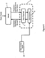
- FIG 4 shows the third control mode 24 of the vessel stabiliser control system 12 where neither the vessel motion sensor nor the precession axis motion sensor signals are available.
- the third control mode 24 is therefore a passive or manually operated control mode.
- the control signal for the gyro-actuator 8 can be a pre-set fixed value gain to provide a predetermined precession damping.
- Such a passive control provides low performance because the fixed level of precession axis braking or damping must be conservatively set to limit precession angles and/or forces within a predefined range in a maximum design sea state or expected range of operating conditions.
- the passive control mode will not therefore provide adequate performance in low sea states because it does not adapt or vary the precession torque directly.
- the third control mode 24 can include locking the additional stabilising device or preferably placing it in a default or disabled state.
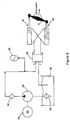
- FIG. 5 is a simplified circuit diagram of one possible hydraulic control circuit to provide precession axis braking or damping torque for a gyrostabiliser 4.
- the gyro-actuator 8 is provided by two hydraulic cylinders 30 in the hydraulic control circuit.
- the hydraulic control circuit is designed such that the hydraulic cylinders 30 pump fluid around a circuit in the direction indicated by the arrows.
- An electronically controlled proportional (or servo) flow control valve 32 which is normally closed (when not energised), is located in-line. In normal operation the hydraulic oil is pumped across the proportional flow control valve 32, which restricts oil flow to create a variable resistance to precession.
- the proportional control valve 32 will be energised open by an amount determined by the control algorithms. By varying the flow settings on the valve 32, the flow is damped.
- the proportional flow control valve 32 is controlled by a dedicated amplifier.
- the proportional control valve 32 closes preventing flow across it.
- an electronically activated directional flow control valve (on/off) 34 opens to allow the oil to flow across a manually adjustable pressure compensated proportional flow control valve 36.
- the directional flow control valve 34 is connected in series with the manually adjustable proportional flow control valve 36, and both are connected in-line parallel to the electronically controlled proportional flow control valve 32.
- the directional control valve 34 is normally open (when not energised). To maintain this valve closed for normal gyrostabiliser operation, a solenoid coil is required to be energised with, for example, a 24 VDC supply at 0.9amps.
- a manually set pressure relief valve 38 is also provided in-line, parallel to the electronically controlled proportional flow control valve 32, to ensure that the pressure drop across the control valves does not exceed the hydraulic system design pressure.
- the set-point of this pressure relief valve effectively caps the precession control torque that is applied to the precession axis.
- a pressure filter 40 removes impurities from the hydraulic fluid in the circuit. If required, an hydraulic fluid heat exchanger 42 and an hydraulic fluid pressure accumulator 44 may be provided.
- an optional manual hydraulic fluid pump system 46 may be connected to a hydraulic control fluid storage device 48, to allow initial hydraulic system filling and system fluid refill or replacement as required.
- a control manifold can be used to switch from the damping hydraulic control circuit of Figure 5 to a driving hydraulic control circuit shown in Figure 6 .
- the hydraulic cylinders 30 are cross-connected (in a quadrant back and forth) in a driving control hydraulic circuit similar to that used, for example, in ship steering and fin stabiliser actuation.
- Hydraulic fluid is drawn from hydraulic fluid tank 56 through suction filter 58 by a fixed or variable flow rate hydraulic pump 60 driven by the motor 62.
- the fluid is passed through the pressure filter 64 into an hydraulic pressure accumulator 66 to provide a supply of high pressure fluid for control.
- a proportional directional control valve 68 connects the supply of high pressure fluid at port P to either the A port to actuate the cross-connected hydraulic cylinders 30 to drive the precession axis in one direction, or the B port to actuate the cross-connected hydraulic cylinders 30 to drive the precession axis in the opposite direction.
- the ports A or B of the proportional directional control valve 68 When one of the ports A or B of the proportional directional control valve 68 is connected to one chamber in each hydraulic cylinder 30, the other chamber of each cylinder is connected to the port T to return fluid to the tank 56 and permit the hydraulic cylinders 30 to extend and contract.
- the hydraulic control circuit for precession damping control, (for example of Figure 5 ) and the hydraulic control circuit for precession driving control, (for example of Figure 6 ) can both be built into a single hydraulic manifold.
Description
- The present invention relates to a control system and method for stabilising marine vessel motion induced by excitation wave forces that produce roll motion and relates particularly, though not exclusively, to such a system and method which includes a gyrostabiliser and employs several control modes to provide fault tolerant control.
- When a gyrostabiliser is used in a marine vessel to attenuate rolling motion, the rolling motion of the vessel induces flywheel precession that in turn produces a torque that opposes the rolling motion. This means that the induced flywheel precession is always in an appropriate phase to attenuate rolling motion (if the precession does not exceed 90°). Depending on the resistance to precession caused by the mechanical arrangement, when the rolling rate of rotation (roll rate) exceeds a certain level, the induced precession torque will cause the flywheel to precess through more than 90° (over-precess). This causes instability in the roll resisting torque produced by the flywheel as it momentarily becomes zero. If the resistance to precession is great enough to prevent induced over-precession during peak input events, the stabilising effect during more common events will be severely limited. It is therefore desirable to provide a gyrostabiliser control system to either vary the resistance to precession, or actively control the flywheel precession motion of the gyroscope.
- There are many known gyrostabiliser control systems, from the manual precession axis brake actuated by a lever to active control of the precession angle in dependence typically on sensed vessel roll motion and gyroscope precession motion. The manual precession axis brake, first proposed by Schlick in 1904 and described by White in 1907, required manual intervention to prevent over-precession in wave environments outside a small range of design conditions.
- The American company Sperry then developed a system that addressed the problem of the Schlick gyroscope by using an electric motor controlled by switches and a small gyroscope to control the precession of the main gyroscope. In this system the rate of precession was proportional to the roll rate of the vessel. Although the performance of these prior art systems was remarkable in some wave environments, (up to 95% roll reduction), the precession control systems were not able to adapt to varying wave conditions, so the performance was limited by simplistic precession torque controls. With the invention of lighter and cheaper fin stabilisers, which work well when a ship is at speed allowing hydrodynamic lift to be produced by the fins, interest in gyrostabilisers waned.
- Gyrostabilisers have particular benefits for applications where the vessel has zero or low forward speed, when hydrodynamics based systems have little or no effect. Several applications including, but not limited to, patrol boats, luxury motor yachts, offshore floating production systems and offshore work boats all have significant operational roles at low or zero speed. These applications are driving renewed interest in revisiting gyrostabilisers for controlling wave induced ship rolling motion.
-
WO 2009/049371 discloses a method of stabilising an oscillating motion of a vessel by actively controlling precession by applying a braking torque when precession exceeds a threshold. -
WO 2006/058372 discloses gyroscope control of vessel motion wherein the gyroscope is mounted on a rail system to enable athwart the vessel to provide a reactive torque to counter heeling motion generated by a gust of wind. -
WO 2009/009074 discloses control system architecture and algorithm to manage a gyrostabilization system for a marine craft. -
US 2005/274210 is directed to a flywheel spin rate controlled gyroscopic stabilizer for a small boat. - As a result, there have been proposed more complex control systems for gyrostabilisers to provide improved vessel motion attenuation performance over a wide range of operating conditions. For example, in
WO 2009/009074 , Rubenstein and Akers disclose a control strategy using attitude and angular rate sensors for both the vessel and the gyrostabiliser to produce a feed forward component. This is used along with a feedback component, a mode input (indicative of current events such as launching, parked or underway at various speeds) and an anticipation of the effect of the intended control (when applied to the gyrostabiliser and/or other vessel stabilising devices) to produce a resource allocation vector for the gyro and any other control means. By actively controlling the precession of the gyrostabiliser flywheel, safe and effective performance across a wide range of operating conditions can be achieved. Active control of the precession requires sensor feedback for use as process control variable(s). If a process control variable becomes unavailable to the control system due to sensor error, loss of system power or other failure, the active control system will cease to operate. For actively driven gyrostabilisers, this will result in immediate loss of the stabilising influence of the gyrostabiliser, which risks the safe and/or comfortable operation of the vessel. - With the provision of increasing numbers of sensors to permit more complex gyrostabiliser control algorithms that are more responsive to changing sea states and vessel motion, the risk of one or more sensors failing is increased.
- The present invention was developed with a view to providing a gyrostabiliser control system and method that is fault tolerant, reducing the severity of the risk of one or more sensors failing. However it will be appreciated that the control system and method of the invention also has application to other types of vessel stabilisers, such as hydrodynamic stabilisers. Examples, of hydrodynamic stabilisers include fins, rudders, T-foils, interceptors, flume tanks or transom flaps and examples of other types of stabilising device include moveable ballast systems.
- References to prior art in this specification are provided for illustrative purposes only and are not to be taken as an admission that such prior art is part of the common general knowledge in Australia or elsewhere.
- According to one aspect of the present invention there is provided a stabiliser control method for stabilising marine vessel motion induced by excitation wave forces, the method comprising the steps of:
- detecting the availability or otherwise of a precession motion sensor signal and the availability or otherwise of a vessel roll motion sensor signal;
- selecting a first control mode when both the sensor signals are available;
- selecting a second control mode when only one of the sensor signals is available; and,
- selecting a third control mode when both sensor signals are unavailable, and using the selected first, second or third control mode to provide control of the stabiliser that is tolerant to the unavailability of the precession motion sensor signal and/or the vessel roll motion sensor signal.
- Typically the precession motion sensor signal is obtained by sensing the precession of a gyrostabiliser which is being employed in a vessel stabilising system to stabilise the vessel. Alternatively, or additionally, in some situations the precession motion sensor signal may be obtained, for example, by sensing the precession motion of a gyroscopic sensor provided for sensing vessel motion. The vessel stabilising system may or may not employ a gyrostabiliser, however in the preferred embodiment the vessel stabilising system employs at least one gyrostabiliser.
- The first control mode may involve active control of the precession of the gyrostabiliser using both sensor signals and/or derivatives of the sensor signals as process control variables by either driving the precession or actively resisting the roll induced free precession of the flywheel to produce a desired precession motion. The first control mode may include Proportional Integral Derivative (PID) controllers, fuzzy logic controllers, neural network control, robust controllers, model predictive control methods, adaptive control methods including the Automatic Gain Control (AGC) controller of the Applicant's co-pending International Application No PCT/AU2011/XXXX, or combinations of these control approaches. The first control mode may respond to a force allocation method which senses the actions of other stabilising devices and adjusts the gyrostabiliser controller accordingly to provide an optimised system of stabilising devices. The first mode of control may require or allow for operator input. The first control mode may use the measured precession axis and vessel roll axis data directly as process control variables or it may include a predictive element which provides estimates of future states of these signals which are then used as inputs to the various possible first control mode methods of control.
- The second control mode may involve active control of the precession of the gyrostabiliser using either the gyrostabiliser precession motion sensor signal or the vessel roll motion sensor signal and/or derivatives of the signal as a process control variable by either driving the precession or actively damping the roll induced free precession of the flywheel to produce a desired precession motion. Alternatively the second control mode may include the step of: calculating appropriate precession axis driving or damping control commands using either predictive or reactive control methods with or without adaptive capability, based on the gyrostabiliser precession motion sensor signal and/or its calculated derivatives. Preferably the second control mode includes the steps of: estimating the precession motion from the vessel roll motion sensor signal; and, calculating appropriate precession axis driving or damping control commands using either predictive or reactive control methods with or without adaptive capability, based on the estimated precession motion and/or its calculated derivatives. Advantageously the second control mode employs an adaptive control method including the steps of: generating a control signal aimed at increasing the precession of the gyrostabiliser flywheel until it is estimated, based on a process control variable derived from the gyrostabiliser precession axis motion, that the gyrostabiliser precession axis motion will exceed a predefined limit; and, applying a precession control torque about the gyrostabiliser precession axis responsive to the control signal whereby, in use, active adaptive control of the vessel motion can be achieved based only on the process control variable derived from the gyrostabiliser precession axis motion.
- Additionally or alternatively, when the gyrostabiliser precession motion sensor signal is unavailable, the vessel roll motion sensor signal and/or its derivatives may be used to generate an estimated precession signal corresponding to an estimate of the gyrostabiliser precession axis motion, the estimated precession signal being substituted for the gyrostabiliser precession motion sensor signal in the second control mode.
- Preferably the third control mode provides passive control of the precession of the gyrostabiliser by applying a conservative preset level of braking or damping to the precession axis designed to limit precession angles to within a predefined limit in up to a maximum design sea state over the expected range of operating conditions. Optionally the preset level of braking or damping applied to the precession axis is manually adjustable.
- The vessel stabilising system may include an additional vessel stabilising device such as an additional gyrostabiliser (to permit control of both roll and pitch for example), a hydrodynamic stabiliser and/or another type of stabilising device. Examples of hydrodynamic stabilisers include fins, rudders, T-foils, interceptors, flume tanks or transom flaps, and examples of other types of stabilising device include moveable ballast systems. The first control mode may include the step of controlling the additional stabilising device simultaneously with the control of the gyrostabiliser and/or as allocated by a force allocation system. The second control mode may include the step of controlling the additional stabilising device. The third control mode may include the step of placing the additional stabilising device in a default or disabled state.
- The control method may include the further step of sensing the availability of the gyrostabiliser and of any additional stabilising devices and modifying a force allocation to suit the loss of availability, or a reduction in performance of one or more of the stabilising devices.
- According to another aspect of the present invention there is provided a stabiliser control system for stabilising marine vessel motion induced by excitation wave forces, the system comprising:
- fault detecting means for detecting the availability or otherwise of a precession motion sensor signal and the availability or otherwise of a vessel roll motion sensor signal;
- control mode selecting means for selecting a first control mode when both the sensor signals are available, selecting a second control mode when only one of the sensor signals is available, and selecting a third control mode when both sensor signals are unavailable; and,
- stabilising control command generating means for generating a stabilising control command in accordance with the selected control mode, and the stabiliser control system selects the first, second or third mode to provide control of the stabiliser that is tolerant to the unavailability of the precession motion sensor signal and/or the vessel roll motion sensor signal.
- Typically the precession motion sensor signal is obtained by sensing the precession of a gyrostabiliser which is being employed in a vessel stabilising system to stabilise the vessel. Alternatively, or additionally, in some situations the precession motion sensor signal may be obtained, for example, by sensing the precession motion of a gyroscopic sensor provided for sensing vessel motion. The vessel stabilising system may or may not employ a gyrostabiliser, however in the preferred embodiment the vessel stabilising system employs at least one gyrostabiliser.
- The stabilising control command generated in the first control mode may provide active control of the precession of the gyrostabiliser using both sensor signals and/or derivatives of the sensor signals as process control variables by either driving the precession or actively resisting the roll induced free precession of the flywheel to produce a desired precession motion.
- Likewise the stabilising control command generated in the second control mode may provide active control of the precession of the gyrostabiliser using either the gyrostabiliser precession motion sensor signal or the vessel roll motion sensor signal and/or derivatives of the signal as a process control variable by either driving the precession or actively damping the roll induced free precession of the flywheel to produce a desired precession motion.
- Typically the stabilising control command generating means comprises: means for calculating appropriate precession axis driving or damping control commands in the second control mode using either predictive or reactive control methods with or without adaptive capability, based on the gyrostabiliser precession motion sensor signal and/or its calculated derivatives.
- Optionally the stabilising control command generating means comprises: means for estimating the precession motion from the vessel roll motion sensor signal in the second control mode; and, means for calculating appropriate precession axis driving or damping control commands using either predictive or reactive control methods with or without adaptive capability, based on the estimated precession motion and/or its calculated derivatives.
- Throughout the specification, unless the context requires otherwise, the word "comprise" or variations such as "comprises" or "comprising", will be understood to imply the inclusion of a stated integer or group of integers but not the exclusion of any other integer or group of integers. Likewise the word "preferably" or variations such as "preferred", will be understood to imply that a stated integer or group of integers is desirable but not essential to the working of the invention.
- Throughout this specification the term "vessel" refers to a marine floating platform, typically a boat, yacht, barge, ship or submarine, which is subject to oscillating motion due to induced excitation forces that produce roll motion. The term "roll motion" refers to the rolling motion of the vessel including any or all derivatives thereof, but more broadly refers to any oscillating motion of the vessel that it is desired to be attenuated.
- The nature of the invention will be better understood from the following detailed description of preferred embodiments of the vessel stabiliser control system and method, given by way of example only, with reference to the accompanying drawings, in which:
-
Figure 1 is a schematic view of a preferred embodiment of a vessel stabiliser control system according to the present invention; -
Figure 2 is a schematic view of the control system ofFigure 1 when operating in a first control mode; -
Figure 3 is a schematic view of the control system ofFigure 1 when operating in a second control mode; -
Figure 4 is a schematic view of the control system ofFigure 1 when operating in a third control mode; -
Figure 5 is a fluid circuit diagram of a preferred embodiment of a gyrostabiliser hydraulic control circuit providing damping control of the precession axis; and, -
Figure 6 is a fluid circuit diagram of a preferred embodiment of a gyrostabiliser hydraulic control circuit providing driven control of the precession axis. -
Figure 1 illustrates the architecture of a preferred embodiment of a vesselstabiliser control system 12 according to the present invention for stabilising the roll motion of amarine vessel 2 induced by excitation wave forces. A gyrostabiliser 4 is employed in the vessel stabilising system for stabilising thevessel 2, and is oriented such that roll motion of thevessel 2 induces precession motion of the gyrostabiliser 4 about its precession axis. The gyrostabiliser 4 is mechanically coupled to a gyro-actuator 8, such that motion of the gyrostabiliser 4 results in displacement of the gyro-actuator 8. The roll motion of thevessel 2 is transferred to aflywheel 6 of the gyrostabiliser 4, and the precession action of theflywheel 6 produces a gyroscopic stabilising moment that counteracts the moment induced by the wave forces. Although this embodiment is described for a roll motion attenuation application, the invention is equally applicable to the attenuation of pitch motions. - Gyroscopic flywheels have two degrees of freedom: spin and precession. By conservation of angular momentum due to spin and the location of the vessel hull, the
flywheel 6 produces a gyroscopic roll moment proportional to the product of the flywheel's spin angular momentum (inertia x angular velocity) and precession rate. The spin rate is generally constant, but this can also be controlled. Hence the larger the precession rate of the flywheel, the larger the gyroscopic stabilising moment produced on the vessel. However, the precession rate and angle must be limited to ensure maximum mechanical loads and other physical constraints are not exceeded, and to prevent excessive precession angles where the effective stabilising torque is reduced but non-useful torques in other planes become significant. The limiting of the precession is achieved by the gyro-actuator 8 which is typically either a hydraulic, electrical or a combination system that provides a braking and/or driving torque about the precession axis. - The action of the gyro-
actuator 8 is regulated or controlled by the vesselstabiliser control system 12. A vesselroll motion sensor 14 provides roll angle measurements for the vesselstabiliser control system 12. Typically a gyroprecession motion sensor 10 provides precession angle measurements of the gyrostabiliser 4 for the vesselstabiliser control system 12. The vesselstabiliser control system 12 processes the process control variables provided by thesensors actuator 8. - The vessel stabilising system may or may not employ a gyrostabiliser, although in the illustrated embodiment the stabilising system employs at least one gyrostabiliser 4. In some situations the vessel stabilising system may employ a hydrodynamic stabiliser and no gyrostabiliser. In that case, the precession motion sensor signal may be obtained, for example, by sensing the precession motion of a gyroscopic sensor provided for sensing vessel motion.
- The vessel
stabiliser control system 12 includes a sensor fault detection means 16 which senses the availability of sensing signals from the gyrostabiliserprecession motion sensor 10 and the vesselroll motion sensor 14. The benefit of employing fault sensing of the sensors providing the process control variables, is that the sensed number of available process control variables (or sensors) can be used to activate a tiered system of control modes. Each tiered control mode is designed to utilise the available process control variables to ensure safe and effective operation of the gyrostabiliser 4 that is tolerant of sensor faults and loss of power supply. Acontrol mode selector 18 is provided for selecting the appropriate- control mode based on the number of available process control variables. - If the sensor fault detection means 16 determines that both the precession and roll signals from the
sensors control mode selector 18 will select afirst control mode 20.Control mode 20 is the most complex (or top tier) of the three selectable control modes, requiring input of both vessel and gyrostabiliser motion data to provide a high level of performance from the gyrostabiliser 4. - If the sensor fault detection means 16 determines that a signal from only one of the precession and roll
sensors control mode selector 18 will select asecond control mode 22 which is the middle tier of the three selectable control modes. The second control mode requires an input data of only one of either vessel or gyrostabiliser motion to provide a good level of performance from the gyrostabiliser 4. - When the sensor fault detection means 16 determines that the signals from both the precession and roll
sensors control mode selector 18 will select thethird control mode 24. Thethird control mode 24 is the lowest tier of the three selectable control modes, providing passive control of the damping of the precession motion without requiring sensor signals to provide a limited level of performance from the gyrostabiliser 4. - The sensor fault detection means 16, the
control mode selection 18 and the various stabilising control command generation means (including the first, second andthird control modes -
Figure 2 illustrates thefirst control mode 20 of the vesselstabiliser control system 12 where the control system receives both vessel roll motion and gyrostabiliser precession motion signals from therespective sensors first control mode 20 typically provides active control of the gyro-actuator 8, either driving the precession or actively resisting (damping) the roll induced free precession of theflywheel 6 to produce a desired precession motion. If thevessel motion sensor 14 provides a roll angle signal and the gyrostabiliserprecession motion sensor 10 provides a precession angle signal, thecontrol system 12 can differentiate these angle signals to generate rate and acceleration if required. Alternatively, or for redundancy additionally, rate and/or acceleration sensors can be included in thevessel motion sensor 14 and/orprecession motion sensor 10. As acceleration can be integrated to give rate and angle. (albeit with generally less accuracy) any angle, rate or acceleration signal can be provided by the vessel and precession motion sensors, with the derivatives being calculated by the control system. - The first control mode may include Proportional Integral Derivative (PID) controllers, fuzzy logic controllers, neural network control, robust controllers, model predictive control methods, adaptive control methods including the Automatic Gain Control (AGC) controller of Applicant's co-pending International Application No PCT/AU2011/XXXX, or a combination of these and/or other control approaches.
- As other stabilising devices such as fins, rudders, T-foils, interceptors, flume tanks, transom flaps and moveable ballast can also be provided in addition to the gyrostabiliser 4, the
first control mode 20 may respond to a force allocation method which senses the actions of other stabilising devices and adjusts the gyrostabiliser control accordingly to provide an optimised system of stabilising devices. The first control mode may require or allow for operator input, such as for example, how aggressive or conservative the precession axis control should be, what type of control algorithm should be used (particularly if different algorithms excel in different sea states), whether the active control is driving or only braking the precession axis motion, what level of power to operate at, or even what the predicted sea state is at a particular time. Thefirst control mode 20 may be one of several alternate first control modes, each requiring both vessel roll and gyrostabiliser precession motion signals. Thefirst control mode 20 may use the measured precession axis and vessel roll axis data directly as process control variables, or it may include a predictive element which provides estimates of future states of these signals which are then used as inputs to the various possible methods of control in thefirst control mode 20. -
Figure 3 illustrates thesecond control mode 22 of the vesselstabiliser control system 12 where the control system receives only gyrostabiliser precession motion signals from thesensor 10. Thissecond control mode 22 can also provide an active control of the gyrostabiliser precession motion despite the vessel roll motion sensor signal being unavailable. - Alternatively, the
second control mode 22 can use the signal from theprecession motion sensor 10 and/or its derivatives to calculate precession axis driving or resistance control commands for the gyro-actuator 8 using either predictive or reactive control methods, with or without adaptive capability. - The
second control mode 22 ofFigure 3 can be, for example, an adaptive control mode using the signal from theprecession motion sensor 10 and its derivatives. One example of such an adaptive control which generates a control signal to control the damping of the gyro-actuator 8 to provide a precession control torque to the gyrostabiliser is the AGC controller of the Applicant's co-pending International Application No PCT/AU2011/ XXXX. The AGC controller gradually reduces the precession damping to increase the precession axis motion until it is sensed that the precession angle or rate will exceed a predefined limit, at which point the damping is increased to prevent over-precession. - In
Figure 3 , the vessel motion sensor signal is not present, so only the precession motion sensor signal is available. Conversely, the precession motion sensor signal can be lost and only the vessel motion sensor signal is available (not illustrated). In this case the precession motion can be estimated from the vessel motion sensor signal and/or its derivatives to generate an estimated precession motion sensor signal to substitute for the lost actual precession motion sensor signal. This estimated, substitute signal can be used to enable operation of according to afirst control mode 20. Alternatively, however, the estimated precession motion sensor signal can be substituted for the actual measured precession motion sensor signal present inFigure 3 . This permits many of various types ofsecond control mode 22 to be used effectively when precession motion sensor signal is unavailable but the vessel motion sensor signal is present. - Multiple
second control modes 22 can be included in the vesselstabiliser control system 12. As with thefirst control mode 20, an operator input or other input can be provided to permit the second control mode algorithm to be adjusted or even alternate control methods or algorithms selected, for example to suit the sea state or change the power consumption of the stabiliser system. The or one of the second control mode(s) 22 can also control additional stabilising devices such as flume tanks or moveable ballast. -
Figure 4 shows thethird control mode 24 of the vesselstabiliser control system 12 where neither the vessel motion sensor nor the precession axis motion sensor signals are available. Thethird control mode 24 is therefore a passive or manually operated control mode. For example, in thethird control mode 24 the control signal for the gyro-actuator 8 can be a pre-set fixed value gain to provide a predetermined precession damping. Such a passive control provides low performance because the fixed level of precession axis braking or damping must be conservatively set to limit precession angles and/or forces within a predefined range in a maximum design sea state or expected range of operating conditions. The passive control mode will not therefore provide adequate performance in low sea states because it does not adapt or vary the precession torque directly. To overcome this limitation, potentially at the risk of not limiting over-precession, a manual adjustment of the damping level can be provided to permit the gyrostabiliser 4 to provide adequate or at least improved performance in low sea states. Where additional stabilising devices are provided, thethird control mode 24 can include locking the additional stabilising device or preferably placing it in a default or disabled state. -
Figure 5 is a simplified circuit diagram of one possible hydraulic control circuit to provide precession axis braking or damping torque for a gyrostabiliser 4. In this case, the gyro-actuator 8 is provided by twohydraulic cylinders 30 in the hydraulic control circuit. The hydraulic control circuit is designed such that thehydraulic cylinders 30 pump fluid around a circuit in the direction indicated by the arrows. An electronically controlled proportional (or servo)flow control valve 32, which is normally closed (when not energised), is located in-line. In normal operation the hydraulic oil is pumped across the proportionalflow control valve 32, which restricts oil flow to create a variable resistance to precession. During normal operation of the gyrostabiliser 4 theproportional control valve 32 will be energised open by an amount determined by the control algorithms. By varying the flow settings on thevalve 32, the flow is damped. The proportionalflow control valve 32 is controlled by a dedicated amplifier. - As a fail-safe measure, if power is removed from the control system (or if the system is in an error state), the
proportional control valve 32 closes preventing flow across it. At the same time an electronically activated directional flow control valve (on/off) 34 opens to allow the oil to flow across a manually adjustable pressure compensated proportionalflow control valve 36. The directionalflow control valve 34 is connected in series with the manually adjustable proportionalflow control valve 36, and both are connected in-line parallel to the electronically controlled proportionalflow control valve 32. Thedirectional control valve 34 is normally open (when not energised). To maintain this valve closed for normal gyrostabiliser operation, a solenoid coil is required to be energised with, for example, a 24 VDC supply at 0.9amps. - A manually set
pressure relief valve 38 is also provided in-line, parallel to the electronically controlled proportionalflow control valve 32, to ensure that the pressure drop across the control valves does not exceed the hydraulic system design pressure. The set-point of this pressure relief valve effectively caps the precession control torque that is applied to the precession axis. Apressure filter 40 removes impurities from the hydraulic fluid in the circuit. If required, an hydraulicfluid heat exchanger 42 and an hydraulicfluid pressure accumulator 44 may be provided. In addition, an optional manual hydraulicfluid pump system 46, with inbuilt filtering, may be connected to a hydraulic controlfluid storage device 48, to allow initial hydraulic system filling and system fluid refill or replacement as required. - To provide a hydraulic system to drive precession axis motion, a control manifold can be used to switch from the damping hydraulic control circuit of
Figure 5 to a driving hydraulic control circuit shown inFigure 6 . InFigure 6 , thehydraulic cylinders 30 are cross-connected (in a quadrant back and forth) in a driving control hydraulic circuit similar to that used, for example, in ship steering and fin stabiliser actuation. Hydraulic fluid is drawn fromhydraulic fluid tank 56 throughsuction filter 58 by a fixed or variable flow ratehydraulic pump 60 driven by themotor 62. The fluid is passed through thepressure filter 64 into anhydraulic pressure accumulator 66 to provide a supply of high pressure fluid for control. A proportionaldirectional control valve 68 connects the supply of high pressure fluid at port P to either the A port to actuate the cross-connectedhydraulic cylinders 30 to drive the precession axis in one direction, or the B port to actuate the cross-connectedhydraulic cylinders 30 to drive the precession axis in the opposite direction. When one of the ports A or B of the proportionaldirectional control valve 68 is connected to one chamber in eachhydraulic cylinder 30, the other chamber of each cylinder is connected to the port T to return fluid to thetank 56 and permit thehydraulic cylinders 30 to extend and contract. - The hydraulic control circuit for precession damping control, (for example of
Figure 5 ) and the hydraulic control circuit for precession driving control, (for example ofFigure 6 ) can both be built into a single hydraulic manifold. - Throughout this specification, when the angle of precession or roll is measured it is implied that the derivatives of this signal then become available for use as process control variables, as differentiating the angle signal is a simple task for a processor in the control system.
- Now that preferred embodiments of the vessel stabiliser control system and method have been described in detail, it will be apparent that the described embodiments provide a number of advantages over the prior art, including the following:
- (i) By providing fault sensing of process control variables or sensors, and using the sensed number of available process control variables to activate a tiered system of control modes, it is possible to ensure safe and effective operation of the vessel stabiliser that is tolerant of sensor faults and loss of power supply.
- (ii) Different levels of control performance can be provided for the stabiliser depending on available resources and sea state.
- (iii) By combining two or more of the control modes improved fault-tolerance can be achieved.
- It will be readily apparent to persons skilled in the relevant arts that various modifications and improvements may be made to the foregoing embodiments, in addition to those already described, without departing from the basic inventive concepts of the present invention. Therefore, it will be appreciated that the scope of the invention is not limited to the specific embodiments described and is to be determined from the appended claims.
Claims (15)
- A stabiliser (4) control method for stabilising marine vessel (2) motion induced by excitation wave forces, the method characterised by: detecting the availability or otherwise of a precession motion sensor (10) signal and the availability or otherwise of a vessel roll motion sensor (14) signal; selecting a first control mode (20) when both the sensor signals are available; selecting a second control mode (22) when only one of the sensor signals is available; and, selecting (18) a third control mode (24) when both sensor signals are unavailable, and using the selected first, second or third control mode to provide control of the stabiliser (4) that is tolerant to the unavailability of the precession motion sensor signal and/or the vessel roll motion sensor signal.
- A stabiliser (4) control method as defined in claim 1, wherein the precession motion sensor signal is obtained by sensing the precession of a gyrostabiliser (4) employed in a vessel stabilising system for stabilising the vessel (2).
- A stabiliser (4) control method as defined in claim 2, wherein the first control mode (20) involves active control of the precession of the gyrostabiliser (4) using both sensor signals and/or derivatives of the sensor signals as process control variables by either driving the precession or actively resisting the roll induced free precession of flywheel (6) to produce a desired precession motion.
- A stabiliser (4) control method as defined in claim 2, wherein the second control mode (22) involves active control of the precession of the gyrostabiliser (4) using either the gyrostabiliser precession motion sensor signal or the vessel roll motion sensor signal and/or derivatives of the signal as a process control variable by either driving the precession or actively damping the roll induced free precession of the flywheel (6) to produce a desired precession motion.
- A stabiliser (4) control method as defined in claim 2, wherein the second control mode (22) includes the step of: calculating appropriate precession axis driving or damping control commands using either predictive or reactive control methods with or without adaptive capability, based on the gyrostabiliser precession motion sensor signal and/or its calculated derivatives.
- A stabiliser (4) control method as defined in claim 2, wherein the second control mode (22) includes the steps of: estimating the precession motion from the vessel roll motion sensor signal; and calculating appropriate precession axis driving or damping control commands using either predictive or reactive control methods with or without adaptive capability, based on the estimated precession motion and/or its calculated derivatives.
- A stabiliser (4) control method as defined in claim 2, wherein the second control mode (22) employs an adaptive control method including the steps of: generating a control signal aimed at increasing the precession of the gyrostabiliser flywheel until it is estimated, based on a process control variable derived from the gyrostabiliser precession axis motion, that the gyrostabiliser precession axis motion will exceed a predefined limit; and, applying a precession control torque about the gyrostabiliser precession axis responsive to the control signal whereby, in use, active adaptive control of the vessel motion can be achieved based only on the process control variable derived from the gyrostabiliser precession axis motion.
- A stabiliser (4) control method as defined in claim 2 or claim 7, wherein when the gyrostabiliser precession motion sensor signal is unavailable, the vessel roll motion sensor signal and/or its derivatives are/is used to generate an estimated precession signal corresponding to an estimate of the gyrostabiliser precession axis motion, the estimated precession signal being substituted for the gyrostabiliser precession motion sensor signal in the second control mode (22).
- A stabiliser (4) control method as defined in claim 2, wherein the third control mode (24) provides passive control of the precession of the gyrostabiliser (4) by applying a conservative preset level of braking or damping to the precession axis designed to limit precession angles to within a predefined limit in up to a maximum design sea state over the expected range of operating conditions.
- A stabiliser (4) control method as defined in claim 9, wherein the preset level of braking or damping applied to the precession axis is manually adjustable.
- A stabiliser (4) control method as defined in claim 2, wherein the vessel control stabilising system includes an additional vessel stabilising device.
- A stabiliser (4) control method as defined in claim 11, wherein the first control mode (20) includes the step of controlling the additional stabilising device simultaneously with the control of the gyrostabiliser (4) and/or as allocated by a force allocation system.
- A stabiliser (4) control method as defined in claim 11, wherein the second control mode (22) includes the step of controlling the additional stabilising device.
- A stabiliser control system (12) for stabilising marine vessel (2) motion induced by excitation wave forces, the system being characterised by: fault detecting means for detecting the availability or otherwise of a precession motion sensor (10) signal and the availability or otherwise of a vessel roll motion sensor (14) signal; control mode selecting means (18) for selecting a first control mode (20) when both the sensor signals are available, selecting a second control mode (22) when only one of the sensor signals is available, and selecting a third control mode (24) when both sensor signals are unavailable; and stabilising control command generating means for generating a stabilising control command in accordance with the selected control mode (20,22,24), and the stabiliser control system selects the first, second or third control mode to provide control of the stabiliser (4) that is tolerant to the unavailability of the precession motion sensor signal and/or the vessel roll motion sensor signal.
- A stabiliser control system (12) according to claim 14 and adapted to perform a method according to any one of claims 2 to 13.
Applications Claiming Priority (2)
| Application Number | Priority Date | Filing Date | Title |
|---|---|---|---|
| AU2010900643A AU2010900643A0 (en) | 2010-02-17 | Gyrostabiliser Control System | |
| PCT/AU2011/000169 WO2011100797A1 (en) | 2010-02-17 | 2011-02-17 | Fault tolerant vessel stabiliser control system |
Publications (3)
| Publication Number | Publication Date |
|---|---|
| EP2536999A1 EP2536999A1 (en) | 2012-12-26 |
| EP2536999A4 EP2536999A4 (en) | 2017-04-05 |
| EP2536999B1 true EP2536999B1 (en) | 2018-07-25 |
Family
ID=44482403
Family Applications (2)
| Application Number | Title | Priority Date | Filing Date |
|---|---|---|---|
| EP11744194.9A Active EP2536999B1 (en) | 2010-02-17 | 2011-02-17 | Fault tolerant vessel stabiliser control system |
| EP11744193.1A Active EP2536998B1 (en) | 2010-02-17 | 2011-02-17 | Active adaptive gyrostabiliser control system |
Family Applications After (1)
| Application Number | Title | Priority Date | Filing Date |
|---|---|---|---|
| EP11744193.1A Active EP2536998B1 (en) | 2010-02-17 | 2011-02-17 | Active adaptive gyrostabiliser control system |
Country Status (7)
| Country | Link |
|---|---|
| US (2) | US8899166B2 (en) |
| EP (2) | EP2536999B1 (en) |
| JP (2) | JP5827245B2 (en) |
| CN (2) | CN102859322B (en) |
| AU (2) | AU2011217739B2 (en) |
| SG (2) | SG183360A1 (en) |
| WO (2) | WO2011100796A1 (en) |
Families Citing this family (30)
| Publication number | Priority date | Publication date | Assignee | Title |
|---|---|---|---|---|
| US8899166B2 (en) | 2010-02-17 | 2014-12-02 | Veem Ltd. | Active adaptive gyrostabiliser control system |
| EP2685093B1 (en) | 2012-07-10 | 2016-06-29 | Alstom Wind, S.L.U. | Wind turbine stabilization |
| GB2508400B (en) * | 2012-11-30 | 2016-12-28 | Univ Southampton | Gyroscopic system |
| ITTO20130500A1 (en) | 2013-06-18 | 2014-12-19 | Item Mare S R L | GYROSCOPIC STABILIZER FOR BOATS |
| DE102013015702B3 (en) * | 2013-09-20 | 2014-12-24 | Audi Ag | Rotary damper for a motor vehicle |
| CN105365914A (en) * | 2014-08-19 | 2016-03-02 | 北京凌云智能科技有限公司 | Electric two-wheel automobile |
| CN104199464B (en) * | 2014-08-19 | 2017-01-18 | 哈尔滨工程大学 | Real-time environment optimum heading ship dynamic positioning control method based on environment estimation |
| CN104192279A (en) * | 2014-09-16 | 2014-12-10 | 哈尔滨恒誉名翔科技有限公司 | Fuzzy immune control based low-speed fin stabilizer control method |
| CN105292395B (en) * | 2015-10-29 | 2017-10-27 | 上海矶怃科技有限公司 | A kind of gyrostabilizer peculiar to vessel and its subtract and shake gyrorotor system |
| WO2017135588A2 (en) * | 2016-02-02 | 2017-08-10 | 주식회사 삼미정공 | Inertial stabilizer for maritime transportation means and method for controlling same |
| KR101667411B1 (en) * | 2016-02-05 | 2016-10-19 | 주식회사 삼미정공 | Anti-rolling gyro stabilizer for means of marine-transportation and control method of the same |
| CN105667731A (en) * | 2016-03-31 | 2016-06-15 | 青岛科技大学 | Marine damping device based on gyroscope damping instrument and working method |
| AU2017216483B2 (en) * | 2016-08-19 | 2023-02-23 | Veem Ltd | Gyrostabilisers |
| KR101831157B1 (en) * | 2016-08-30 | 2018-04-04 | 재단법인한국조선해양기자재연구원 | A gyro stabilizer with power generation system and damping device |
| CN107021191A (en) * | 2017-04-01 | 2017-08-08 | 东南大学 | One kind balance ship |
| KR101954175B1 (en) * | 2017-08-29 | 2019-03-05 | 주식회사 삼미정공 | Power system of leisure boat using a gyroscope |
| CN107992063B (en) * | 2017-12-29 | 2020-08-04 | 哈尔滨工业大学 | Variable-parameter nutation damping-based precession control method for variable-speed tilting momentum wheel |
| US11649017B2 (en) | 2018-05-31 | 2023-05-16 | Wavetamer Llc | Gyroscopic boat roll stabilizer |
| GB2575315B (en) * | 2018-07-06 | 2021-01-13 | Sleipner Motor As | Boat stabilizer fin powered by precession torque of stabilizing gyro |
| US11027786B2 (en) * | 2018-11-20 | 2021-06-08 | Harley-Davidson Motor Company Group, LLC | Gyroscopic rider assist device |
| DE102019108476A1 (en) * | 2019-04-01 | 2020-10-01 | Moog Gmbh | Hydraulic system for stabilizer drive |
| US11440629B2 (en) | 2019-04-03 | 2022-09-13 | Wavetamer Llc | Braking system for gyroscopic boat roll stabilizer |
| CN111017128A (en) * | 2019-12-23 | 2020-04-17 | 云南农业大学 | Stable anti-tilting boat with gyroscope |
| CN111221244A (en) * | 2020-01-15 | 2020-06-02 | 哈尔滨工程大学 | Ship rudder rolling reduction control method |
| CN111290416B (en) * | 2020-01-20 | 2020-11-20 | 郑州宇通重工有限公司 | Ship attitude control method, system, computer storage medium and ship |
| AU2021231492B2 (en) | 2020-03-02 | 2024-03-07 | Wavetamer Llc | Gyroscopic boat roll stabilizer with bearing cooling |
| EP4204296A4 (en) * | 2020-09-30 | 2023-11-08 | Wavetamer LLC | Gyroscopic roll stabilizer with flywheel shaft through passage |
| US11807344B2 (en) | 2020-09-30 | 2023-11-07 | Wavetamer Llc | Gyroscopic roll stabilizer with flywheel cavity seal arrangement |
| CN113375952B (en) * | 2021-06-08 | 2024-03-19 | 上海衡拓船舶设备有限公司 | Stabilizer device fault diagnosis and health forecasting system |
| WO2023092228A1 (en) * | 2021-11-24 | 2023-06-01 | Dometic Marine Canada Inc. | Roll stabilization and related apparatuses |
Family Cites Families (18)
| Publication number | Priority date | Publication date | Assignee | Title |
|---|---|---|---|---|
| US769493A (en) | 1903-05-11 | 1904-09-06 | Ernst Otto Schlick | Device for minimizing the oscillatory movements of ships. |
| US2790119A (en) | 1950-01-19 | 1957-04-23 | Bendix Aviat Corp | Servosystem stabilized platform |
| US3280642A (en) | 1962-09-28 | 1966-10-25 | Bendix Corp | Directional gyroscope |
| GB9113784D0 (en) | 1991-06-26 | 1991-11-06 | Vickers Plc | Ship stabiliser automatic gain control system |
| JP3601854B2 (en) * | 1994-09-19 | 2004-12-15 | 特許機器株式会社 | Vibration control method by gyro mechanism |
| JPH08297027A (en) * | 1995-04-27 | 1996-11-12 | Komatsu Ltd | Damping device of running working vehicle |
| JPH10246637A (en) * | 1997-03-05 | 1998-09-14 | Shinko Electric Co Ltd | Anti-rolling device |
| CN2574992Y (en) * | 2002-07-01 | 2003-09-24 | 杨庆勇 | Comprehensive controller for boats and ships |
| JP3616778B2 (en) * | 2003-02-12 | 2005-02-02 | 紀孝 松村 | Control method of ship sway reduction device |
| US7181987B2 (en) * | 2003-05-02 | 2007-02-27 | Peter Winston Hamady | Precessional device and method |
| US6973847B2 (en) | 2003-06-04 | 2005-12-13 | Gearloose Engineering, Inc. | Gyroscopic roll stabilizer for boats |
| US20080167768A1 (en) | 2003-10-08 | 2008-07-10 | Marine Motion Control, Llc | Control system for a vessel with a gyrostabilization system |
| WO2006058372A1 (en) | 2004-11-30 | 2006-06-08 | Sea Gyro Pty Ltd | Method and apparatus for controlling motion of a marine vessel |
| ES2471373T3 (en) * | 2005-08-22 | 2014-06-26 | Technology Investment Company Pty Ltd. | Stabilization medium |
| JP5064779B2 (en) * | 2006-12-12 | 2012-10-31 | 義大 須田 | Attitude control device |
| WO2009049371A1 (en) * | 2007-10-16 | 2009-04-23 | Halcyon International Pty Ltd | Gyro-stabiliser |
| CN101634556B (en) * | 2009-08-26 | 2011-07-13 | 北京航天控制仪器研究所 | Small-sized integral type flexible joint and minitype high-speed dynamic tuned gyroscope |
| US8899166B2 (en) | 2010-02-17 | 2014-12-02 | Veem Ltd. | Active adaptive gyrostabiliser control system |
-
2011
- 2011-02-17 US US13/579,520 patent/US8899166B2/en active Active
- 2011-02-17 EP EP11744194.9A patent/EP2536999B1/en active Active
- 2011-02-17 JP JP2012553150A patent/JP5827245B2/en active Active
- 2011-02-17 EP EP11744193.1A patent/EP2536998B1/en active Active
- 2011-02-17 AU AU2011217739A patent/AU2011217739B2/en active Active
- 2011-02-17 SG SG2012060935A patent/SG183360A1/en unknown
- 2011-02-17 CN CN201180019556.XA patent/CN102859322B/en active Active
- 2011-02-17 CN CN201180019577.1A patent/CN102906538B/en active Active
- 2011-02-17 SG SG2012060497A patent/SG183330A1/en unknown
- 2011-02-17 AU AU2011217738A patent/AU2011217738B2/en active Active
- 2011-02-17 JP JP2012553151A patent/JP5827959B2/en active Active
- 2011-02-17 WO PCT/AU2011/000168 patent/WO2011100796A1/en active Application Filing
- 2011-02-17 US US13/579,517 patent/US8904948B2/en active Active
- 2011-02-17 WO PCT/AU2011/000169 patent/WO2011100797A1/en active Application Filing
Also Published As
| Publication number | Publication date |
|---|---|
| AU2011217738B2 (en) | 2014-01-16 |
| CN102859322B (en) | 2015-06-24 |
| WO2011100796A1 (en) | 2011-08-25 |
| AU2011217739B2 (en) | 2014-01-16 |
| JP2013519887A (en) | 2013-05-30 |
| CN102906538B (en) | 2015-08-05 |
| JP2013519886A (en) | 2013-05-30 |
| AU2011217738A1 (en) | 2012-09-06 |
| WO2011100797A1 (en) | 2011-08-25 |
| JP5827245B2 (en) | 2015-12-02 |
| EP2536999A1 (en) | 2012-12-26 |
| US8899166B2 (en) | 2014-12-02 |
| EP2536998A1 (en) | 2012-12-26 |
| EP2536998B1 (en) | 2018-07-25 |
| AU2011217739A1 (en) | 2012-09-06 |
| CN102906538A (en) | 2013-01-30 |
| CN102859322A (en) | 2013-01-02 |
| US20130036958A1 (en) | 2013-02-14 |
| EP2536999A4 (en) | 2017-04-05 |
| SG183330A1 (en) | 2012-09-27 |
| US20130036959A1 (en) | 2013-02-14 |
| US8904948B2 (en) | 2014-12-09 |
| JP5827959B2 (en) | 2015-12-02 |
| SG183360A1 (en) | 2012-09-27 |
| EP2536998A4 (en) | 2017-04-05 |
Similar Documents
| Publication | Publication Date | Title |
|---|---|---|
| EP2536999B1 (en) | Fault tolerant vessel stabiliser control system | |
| US9694892B1 (en) | System and method for trimming trimmable marine devices with respect to a marine vessel | |
| US9068855B1 (en) | Counter-porpoising watercraft attitude control system | |
| CN110177741B (en) | Method for operating a marine vessel comprising a plurality of propulsion units | |
| JP6351135B2 (en) | System and method for controlling the trim position of a propulsion device on a ship | |
| US9751605B1 (en) | System and method for trimming a trimmable marine device with respect to a marine vessel | |
| WO2011125466A1 (en) | Ship main engine control system and method | |
| JP6471875B2 (en) | System and method for controlling the trim position of a propulsion device on a ship | |
| SE1130084A1 (en) | Method and apparatus for avoiding and attenuating the rolling of a ship | |
| Liu et al. | Ship heading control with speed keeping via a nonlinear disturbance observer | |
| US11383802B2 (en) | Trim tab control system for a ship and a ship with the trim tab control system | |
| JP6704206B2 (en) | Steering machine, ship equipped with the same, and control method for steering machine | |
| JP2004291773A (en) | Rocking reduction system for hull | |
| CA2974575C (en) | System and method for controlling trim position of propulsion device on a marine vessel | |
| JP4401798B2 (en) | Steam turbine ship main turbine torque limiter | |
| Stefanowski | Reduction of ship steering gear load at high sea states by decreasing rudder angular velocity | |
| Yoon et al. | Predictive Control for a Fin Stabilizer | |
| NO337571B1 (en) | Method and system for dynamic positioning of floating vessels in water |
Legal Events
| Date | Code | Title | Description |
|---|---|---|---|
| PUAI | Public reference made under article 153(3) epc to a published international application that has entered the european phase |
Free format text: ORIGINAL CODE: 0009012 |
|
| 17P | Request for examination filed |
Effective date: 20120917 |
|
| AK | Designated contracting states |
Kind code of ref document: A1 Designated state(s): AL AT BE BG CH CY CZ DE DK EE ES FI FR GB GR HR HU IE IS IT LI LT LU LV MC MK MT NL NO PL PT RO RS SE SI SK SM TR |
|
| DAX | Request for extension of the european patent (deleted) | ||
| RA4 | Supplementary search report drawn up and despatched (corrected) |
Effective date: 20170306 |
|
| RIC1 | Information provided on ipc code assigned before grant |
Ipc: G01C 19/02 20060101AFI20170228BHEP Ipc: B63B 39/04 20060101ALI20170228BHEP |
|
| GRAP | Despatch of communication of intention to grant a patent |
Free format text: ORIGINAL CODE: EPIDOSNIGR1 |
|
| STAA | Information on the status of an ep patent application or granted ep patent |
Free format text: STATUS: GRANT OF PATENT IS INTENDED |
|
| INTG | Intention to grant announced |
Effective date: 20180206 |
|
| GRAS | Grant fee paid |
Free format text: ORIGINAL CODE: EPIDOSNIGR3 |
|
| GRAA | (expected) grant |
Free format text: ORIGINAL CODE: 0009210 |
|
| STAA | Information on the status of an ep patent application or granted ep patent |
Free format text: STATUS: THE PATENT HAS BEEN GRANTED |
|
| AK | Designated contracting states |
Kind code of ref document: B1 Designated state(s): AL AT BE BG CH CY CZ DE DK EE ES FI FR GB GR HR HU IE IS IT LI LT LU LV MC MK MT NL NO PL PT RO RS SE SI SK SM TR |
|
| REG | Reference to a national code |
Ref country code: GB Ref legal event code: FG4D |
|
| REG | Reference to a national code |
Ref country code: CH Ref legal event code: EP |
|
| REG | Reference to a national code |
Ref country code: AT Ref legal event code: REF Ref document number: 1022239 Country of ref document: AT Kind code of ref document: T Effective date: 20180815 |
|
| REG | Reference to a national code |
Ref country code: IE Ref legal event code: FG4D |
|
| REG | Reference to a national code |
Ref country code: DE Ref legal event code: R096 Ref document number: 602011050349 Country of ref document: DE |
|
| REG | Reference to a national code |
Ref country code: NL Ref legal event code: FP |
|
| REG | Reference to a national code |
Ref country code: LT Ref legal event code: MG4D |
|
| REG | Reference to a national code |
Ref country code: AT Ref legal event code: MK05 Ref document number: 1022239 Country of ref document: AT Kind code of ref document: T Effective date: 20180725 |
|
| PG25 | Lapsed in a contracting state [announced via postgrant information from national office to epo] |
Ref country code: NO Free format text: LAPSE BECAUSE OF FAILURE TO SUBMIT A TRANSLATION OF THE DESCRIPTION OR TO PAY THE FEE WITHIN THE PRESCRIBED TIME-LIMIT Effective date: 20181025 Ref country code: BG Free format text: LAPSE BECAUSE OF FAILURE TO SUBMIT A TRANSLATION OF THE DESCRIPTION OR TO PAY THE FEE WITHIN THE PRESCRIBED TIME-LIMIT Effective date: 20181025 Ref country code: RS Free format text: LAPSE BECAUSE OF FAILURE TO SUBMIT A TRANSLATION OF THE DESCRIPTION OR TO PAY THE FEE WITHIN THE PRESCRIBED TIME-LIMIT Effective date: 20180725 Ref country code: GR Free format text: LAPSE BECAUSE OF FAILURE TO SUBMIT A TRANSLATION OF THE DESCRIPTION OR TO PAY THE FEE WITHIN THE PRESCRIBED TIME-LIMIT Effective date: 20181026 Ref country code: LT Free format text: LAPSE BECAUSE OF FAILURE TO SUBMIT A TRANSLATION OF THE DESCRIPTION OR TO PAY THE FEE WITHIN THE PRESCRIBED TIME-LIMIT Effective date: 20180725 Ref country code: IS Free format text: LAPSE BECAUSE OF FAILURE TO SUBMIT A TRANSLATION OF THE DESCRIPTION OR TO PAY THE FEE WITHIN THE PRESCRIBED TIME-LIMIT Effective date: 20181125 Ref country code: AT Free format text: LAPSE BECAUSE OF FAILURE TO SUBMIT A TRANSLATION OF THE DESCRIPTION OR TO PAY THE FEE WITHIN THE PRESCRIBED TIME-LIMIT Effective date: 20180725 Ref country code: FI Free format text: LAPSE BECAUSE OF FAILURE TO SUBMIT A TRANSLATION OF THE DESCRIPTION OR TO PAY THE FEE WITHIN THE PRESCRIBED TIME-LIMIT Effective date: 20180725 Ref country code: PL Free format text: LAPSE BECAUSE OF FAILURE TO SUBMIT A TRANSLATION OF THE DESCRIPTION OR TO PAY THE FEE WITHIN THE PRESCRIBED TIME-LIMIT Effective date: 20180725 Ref country code: SE Free format text: LAPSE BECAUSE OF FAILURE TO SUBMIT A TRANSLATION OF THE DESCRIPTION OR TO PAY THE FEE WITHIN THE PRESCRIBED TIME-LIMIT Effective date: 20180725 |
|
| PG25 | Lapsed in a contracting state [announced via postgrant information from national office to epo] |
Ref country code: LV Free format text: LAPSE BECAUSE OF FAILURE TO SUBMIT A TRANSLATION OF THE DESCRIPTION OR TO PAY THE FEE WITHIN THE PRESCRIBED TIME-LIMIT Effective date: 20180725 Ref country code: AL Free format text: LAPSE BECAUSE OF FAILURE TO SUBMIT A TRANSLATION OF THE DESCRIPTION OR TO PAY THE FEE WITHIN THE PRESCRIBED TIME-LIMIT Effective date: 20180725 Ref country code: HR Free format text: LAPSE BECAUSE OF FAILURE TO SUBMIT A TRANSLATION OF THE DESCRIPTION OR TO PAY THE FEE WITHIN THE PRESCRIBED TIME-LIMIT Effective date: 20180725 |
|
| REG | Reference to a national code |
Ref country code: DE Ref legal event code: R097 Ref document number: 602011050349 Country of ref document: DE |
|
| PG25 | Lapsed in a contracting state [announced via postgrant information from national office to epo] |
Ref country code: EE Free format text: LAPSE BECAUSE OF FAILURE TO SUBMIT A TRANSLATION OF THE DESCRIPTION OR TO PAY THE FEE WITHIN THE PRESCRIBED TIME-LIMIT Effective date: 20180725 Ref country code: ES Free format text: LAPSE BECAUSE OF FAILURE TO SUBMIT A TRANSLATION OF THE DESCRIPTION OR TO PAY THE FEE WITHIN THE PRESCRIBED TIME-LIMIT Effective date: 20180725 Ref country code: CZ Free format text: LAPSE BECAUSE OF FAILURE TO SUBMIT A TRANSLATION OF THE DESCRIPTION OR TO PAY THE FEE WITHIN THE PRESCRIBED TIME-LIMIT Effective date: 20180725 Ref country code: RO Free format text: LAPSE BECAUSE OF FAILURE TO SUBMIT A TRANSLATION OF THE DESCRIPTION OR TO PAY THE FEE WITHIN THE PRESCRIBED TIME-LIMIT Effective date: 20180725 |
|
| PG25 | Lapsed in a contracting state [announced via postgrant information from national office to epo] |
Ref country code: SM Free format text: LAPSE BECAUSE OF FAILURE TO SUBMIT A TRANSLATION OF THE DESCRIPTION OR TO PAY THE FEE WITHIN THE PRESCRIBED TIME-LIMIT Effective date: 20180725 Ref country code: DK Free format text: LAPSE BECAUSE OF FAILURE TO SUBMIT A TRANSLATION OF THE DESCRIPTION OR TO PAY THE FEE WITHIN THE PRESCRIBED TIME-LIMIT Effective date: 20180725 Ref country code: SK Free format text: LAPSE BECAUSE OF FAILURE TO SUBMIT A TRANSLATION OF THE DESCRIPTION OR TO PAY THE FEE WITHIN THE PRESCRIBED TIME-LIMIT Effective date: 20180725 |
|
| PLBE | No opposition filed within time limit |
Free format text: ORIGINAL CODE: 0009261 |
|
| STAA | Information on the status of an ep patent application or granted ep patent |
Free format text: STATUS: NO OPPOSITION FILED WITHIN TIME LIMIT |
|
| 26N | No opposition filed |
Effective date: 20190426 |
|
| PG25 | Lapsed in a contracting state [announced via postgrant information from national office to epo] |
Ref country code: SI Free format text: LAPSE BECAUSE OF FAILURE TO SUBMIT A TRANSLATION OF THE DESCRIPTION OR TO PAY THE FEE WITHIN THE PRESCRIBED TIME-LIMIT Effective date: 20180725 |
|
| REG | Reference to a national code |
Ref country code: CH Ref legal event code: PL |
|
| PG25 | Lapsed in a contracting state [announced via postgrant information from national office to epo] |
Ref country code: LU Free format text: LAPSE BECAUSE OF NON-PAYMENT OF DUE FEES Effective date: 20190217 Ref country code: MC Free format text: LAPSE BECAUSE OF FAILURE TO SUBMIT A TRANSLATION OF THE DESCRIPTION OR TO PAY THE FEE WITHIN THE PRESCRIBED TIME-LIMIT Effective date: 20180725 |
|
| REG | Reference to a national code |
Ref country code: BE Ref legal event code: MM Effective date: 20190228 |
|
| REG | Reference to a national code |
Ref country code: IE Ref legal event code: MM4A |
|
| PG25 | Lapsed in a contracting state [announced via postgrant information from national office to epo] |
Ref country code: LI Free format text: LAPSE BECAUSE OF NON-PAYMENT OF DUE FEES Effective date: 20190228 Ref country code: CH Free format text: LAPSE BECAUSE OF NON-PAYMENT OF DUE FEES Effective date: 20190228 |
|
| PG25 | Lapsed in a contracting state [announced via postgrant information from national office to epo] |
Ref country code: IE Free format text: LAPSE BECAUSE OF NON-PAYMENT OF DUE FEES Effective date: 20190217 |
|
| PG25 | Lapsed in a contracting state [announced via postgrant information from national office to epo] |
Ref country code: BE Free format text: LAPSE BECAUSE OF NON-PAYMENT OF DUE FEES Effective date: 20190228 |
|
| PG25 | Lapsed in a contracting state [announced via postgrant information from national office to epo] |
Ref country code: TR Free format text: LAPSE BECAUSE OF FAILURE TO SUBMIT A TRANSLATION OF THE DESCRIPTION OR TO PAY THE FEE WITHIN THE PRESCRIBED TIME-LIMIT Effective date: 20180725 |
|
| PG25 | Lapsed in a contracting state [announced via postgrant information from national office to epo] |
Ref country code: PT Free format text: LAPSE BECAUSE OF FAILURE TO SUBMIT A TRANSLATION OF THE DESCRIPTION OR TO PAY THE FEE WITHIN THE PRESCRIBED TIME-LIMIT Effective date: 20181125 Ref country code: MT Free format text: LAPSE BECAUSE OF NON-PAYMENT OF DUE FEES Effective date: 20190217 |
|
| PG25 | Lapsed in a contracting state [announced via postgrant information from national office to epo] |
Ref country code: CY Free format text: LAPSE BECAUSE OF FAILURE TO SUBMIT A TRANSLATION OF THE DESCRIPTION OR TO PAY THE FEE WITHIN THE PRESCRIBED TIME-LIMIT Effective date: 20180725 |
|
| PG25 | Lapsed in a contracting state [announced via postgrant information from national office to epo] |
Ref country code: HU Free format text: LAPSE BECAUSE OF FAILURE TO SUBMIT A TRANSLATION OF THE DESCRIPTION OR TO PAY THE FEE WITHIN THE PRESCRIBED TIME-LIMIT; INVALID AB INITIO Effective date: 20110217 |
|
| PG25 | Lapsed in a contracting state [announced via postgrant information from national office to epo] |
Ref country code: MK Free format text: LAPSE BECAUSE OF FAILURE TO SUBMIT A TRANSLATION OF THE DESCRIPTION OR TO PAY THE FEE WITHIN THE PRESCRIBED TIME-LIMIT Effective date: 20180725 |
|
| PGFP | Annual fee paid to national office [announced via postgrant information from national office to epo] |
Ref country code: GB Payment date: 20221230 Year of fee payment: 13 |
|
| PGFP | Annual fee paid to national office [announced via postgrant information from national office to epo] |
Ref country code: IT Payment date: 20230110 Year of fee payment: 13 Ref country code: DE Payment date: 20221220 Year of fee payment: 13 |
|
| PGFP | Annual fee paid to national office [announced via postgrant information from national office to epo] |
Ref country code: NL Payment date: 20230113 Year of fee payment: 13 |
|
| P01 | Opt-out of the competence of the unified patent court (upc) registered |
Effective date: 20230525 |
|
| PGFP | Annual fee paid to national office [announced via postgrant information from national office to epo] |
Ref country code: FR Payment date: 20231222 Year of fee payment: 14 |
|
| PGFP | Annual fee paid to national office [announced via postgrant information from national office to epo] |
Ref country code: NL Payment date: 20240108 Year of fee payment: 14 |